EP1557107A1 - Button - Google Patents
Button Download PDFInfo
- Publication number
- EP1557107A1 EP1557107A1 EP05250299A EP05250299A EP1557107A1 EP 1557107 A1 EP1557107 A1 EP 1557107A1 EP 05250299 A EP05250299 A EP 05250299A EP 05250299 A EP05250299 A EP 05250299A EP 1557107 A1 EP1557107 A1 EP 1557107A1
- Authority
- EP
- European Patent Office
- Prior art keywords
- button
- fabric
- fixture
- tip end
- button body
- Prior art date
- Legal status (The legal status is an assumption and is not a legal conclusion. Google has not performed a legal analysis and makes no representation as to the accuracy of the status listed.)
- Granted
Links
Images


Classifications
-
- A—HUMAN NECESSITIES
- A44—HABERDASHERY; JEWELLERY
- A44B—BUTTONS, PINS, BUCKLES, SLIDE FASTENERS, OR THE LIKE
- A44B1/00—Buttons
- A44B1/18—Buttons adapted for special ways of fastening
- A44B1/44—Buttons adapted for special ways of fastening with deformable counterpiece
-
- Y—GENERAL TAGGING OF NEW TECHNOLOGICAL DEVELOPMENTS; GENERAL TAGGING OF CROSS-SECTIONAL TECHNOLOGIES SPANNING OVER SEVERAL SECTIONS OF THE IPC; TECHNICAL SUBJECTS COVERED BY FORMER USPC CROSS-REFERENCE ART COLLECTIONS [XRACs] AND DIGESTS
- Y10—TECHNICAL SUBJECTS COVERED BY FORMER USPC
- Y10T—TECHNICAL SUBJECTS COVERED BY FORMER US CLASSIFICATION
- Y10T24/00—Buckles, buttons, clasps, etc.
- Y10T24/36—Button with fastener
- Y10T24/3611—Deflecting prong or rivet
Definitions
- the present invention relates to a button for buttoning garments and a decorative button mainly used as decoration, specifically, a button to be attached by interposing a fabric between a button body and a fixture.
- buttons attached by interposing a fabric between a button body and a fixture.
- Such button has a button body with a concave portion therein and a fixture with its tip end to be inserted into the concave portion.
- Figs. 4A to 4D show typical examples of this type of conventional button.
- Fig. 4A shows a button body 50 with a common shape, which is widely-used and called "F-bar".
- the button body 50 has an engaging portion 50B with a curved concave portion 50A therein, a folded portion 50C greatly folded back from an opening end of the engaging portion 50B, and a flange 50D extending from the folded portion 50C toward the outside and inclined toward the opening end.
- Fig. 4B shows a button body 51 with a common shape, which is widely-used and called "E-bar".
- the button body 51 has a center portion 51B with a concave portion 51A having a substantially rectangular shape therein, a folded portion 51C slightly folded back from an opening end of the center portion 51B and a flange 51D extending straight from the folded portion 51C toward the outside.
- Fig. 4C shows a shank type rivet 52 as a fixture to be coupled with the button bodies 50, 51.
- the rivet 52 has a flange 52A and a shaft 52B provided at the center of the flange 52A, a tip end of the shaft 52B having a sharp edge.
- Fig. 4D shows a header type rivet 53 as a fixture to be coupled with the button bodies 50, 51.
- the rivet 53 has a flange 53A and a shaft 53B provided at the center of the flange 53A, edges of a tip end of the shaft 53B being cut off.
- a fabric is interposed between the button bodies 50, 51 and the rivets 52, 53.
- the engaging portions 50B, 51B of the button bodies 50, 51 are so formed that parts forming the opening end project from the flanges 50D, 51D to press the fabric. Therefore, since spaces between the flanges 50D, 51D of the button bodies 50, 51 and the flanges 52A, 53A of the rivets 52, 53 are wide, thin fabrics cannot be pressed sufficiently. If the fabric is not pressed sufficiently, the button bodies 50, 51 and the rivets 52, 53 can come off from the fabric unexpectedly. In addition, there is a possibility that foreign bodies or nails of a user are caught between the fabric and the button bodies 50, 51 or the rivets 52, 53.
- forming the flange of the rivet into an inverted-conical shape without changing the shape of the button bodies 50, 51 can be a possible solution, but it is difficult to process the flange into the inverted-conical shape.
- buttons having button bodies and fixtures with specific shapes as shown in Figs. 5A and 5B for attaching a button to a thin fabric.
- Fig. 5A shows a button called “stud”, which has a button body 60 with a concave portion 60A therein and a fixture 61 called “post” and molded with a thin plate.
- the fixture 61 has a flange 61A and a leg 61B formed at the center of the flange 61A, and formed on a tip end of the leg 61B is a flare 61C processed to open toward the outside.
- the fabric is cut between the flare 61C and the concave portion 60A of the button body 60. Therefore, the concave portion 60A of the button body 60 is formed into a specific shape having a narrow opening end and the width being gradually widened toward the inside in order to cut the fabric with the flare 61C.
- Fig. 5B shows a button having a button body 62 called “G-bar” and a fixture 63 called "post rivet”.
- the button body 62 has a specific shape including a front portion 62A formed with its edge folded and an engaging portion 62B with its outer edge engaged with the edge of the front portion 62A and with its inner edge forming a sharp cutting edge 62C.
- the fixture 63 has a flange 63A and a leg 63B formed at the center of the flange 63A, the leg 63B being provided with an inclined portion 63C to cut the fabric with the cutting edge of the engaging portion 62B.
- the button disclosed in Reference 1 has a structure including a button body having a conical projection, an engaging portion with its tip end adapted to bend when abutting on the conical projection and a flange for the engaging portion to be attached to the center thereof, the engaging portion being provided with a plurality of cutting edges arranged circularly to cut the fabric with the button body portion.
- Figs.5A and 5B have a problem in which the attaching structure cannot be utilized for widely-used button bodies such as F-bar and E-bar due to its specific shapes.
- the shape of the concave portion fitted to the flare of the fixture 61 is determined without variation, so that button bodies of the F-bar or E-bar shown in Figs. 4A to 4B" cannot be applied to the fixture 61.
- the flare of the fixture 61 is formed to have thin tip end, when attached to a thick fabric like a denim fabric, the denim fabric cannot be cut sufficiently between the tip end of the flare and the concave portion of the button body. If the fixture 61 is forcibly attached to the thick fabric, the tip end of the flare is deformed, which makes the attachment even more difficult.
- the button disclosed in Reference 1 has a problem in which the cutting edge is deformed or broken when the fabric is thick or stiff.
- the button also has a problem when the fabric is thin or soft, in which the button cannot press the fabric sufficiently and catches the fabric in cutting so that the button cannot be attached to the fabric appropriately.
- An object of the present invention is to provide a button that can be attached to a fabric by using a widely-used button body with common shape regardless of thickness and stiffness of the fabric.
- a button includes: a button body; and a fixture, the fixture being pressed and fixed with a fabric interposed between the button body and the fixture, in which the button body has a housing for a tip end of the fixture to be inserted therein, and the fixture has a shoulder between the tip end and a tubular portion formed continuously from the tip end, the shoulder having a cutting portion to cut the fabric with an insertion end of the housing of the button body.
- the fabric is cut between the cutting portion formed on the shoulder and the insertion end of the housing of the button body while being pressed by the tip end of the fixture, so that the button can be attached.
- the fabric is cut between the cutting portion formed on the shoulder of the fixture and the insertion end of the housing of the button body.
- the plate thickness does not have to be thinned compared with that of the flare or the edge shown in the related art, so that it does not face a problem of being damaged even when a big force is applied to the cutting portion.
- its center alignment capability is not deteriorated. Therefore, in the present invention, the fabric can be easily cut without damaging the fixture regardless of the thickness of the fabric.
- the button body is shaped to have the housing in the present invention, a widely-used button body can be used without making any changes by employing a common shape like F-bar, E-bar, etc.
- the cutting portion is an edge formed on the shoulder.
- the curvature radius R of the edge is 0.5 mm or less, more preferably 0.3 mm or less.
- the cutting portion by providing the cutting portion on the edge formed between the tip end and the tubular portion, processing of the cutting portion can be facilitated, so that the fixture can be manufactured easily.
- the cutting portion is formed continuously or intermittently on the circumference of the shoulder.
- the fabric can be appropriately and easily cut along the insertion end of the housing.
- the shoulder has an outer periphery radially bulged relative to the tubular portion.
- the shoulder is hardly deformed, and the damage on the cutting portion can be prevented more efficiently.
- the tip end has a projection projecting from the shoulder.
- the fabric is stretched and pressed by the projection projecting from the shoulder in cutting the fabric between the cutting portion of the fixture and the insertion portion of the housing of the button body, which facilitates cutting the fabric so that the fabric can be cut smoothly without damaging the cutting portion.
- the tip end is adapted to be dented and bulged outwardly when pressed by the button body so that the bulged tip end is engaged with the housing.
- the lateral side of the tip end pressed the lateral side of the housing sufficiently so that detaching force (separation force) of the button is increased. This prevents the button body from unexpectedly coming off from the fixture.
- the edge 12F as the cutting portion of the present invention and the projection 12E can be provided even if it is processed from a plate, and thus the fabric can be cut easily.
- the thickness of the plate used as a material of the fixture should preferably be in the range of 0.2 mm to 1 mm, more preferably, 0.3 mm to 0.6 mm.
- Fig. 1A is a cross section showing a first embodiment.
- a button 10 has a button body 11 and a fixture 12 attached to each other with a fabric 1 interposed therebetween.
- the button body 11 is called F-bar and has a structure identical to the button body shown in Fig. 4B.
- the button body 11 is made of aluminum, iron, stainless steel alloy, copper alloy including brass or other kind of metals or alloys by an appropriate processing such as press working.
- the button body 11 has a structure in which a center portion 11B provided with a concave portion 11A as a housing, a folded portion 11C slightly folded back from an edge of an opening end as an insertion end of the center portion 11B, a flange 11D extending straight from the folded portion 11C toward the outside are integrally molded.
- the center portion 11B is formed to have a cylindrical shape with a bottom face, and the inner side thereof is the concave portion 11A.
- the concave portion 11A has a substantially rectangular shape with its opening end 11E rounded by appropriate curvature.
- the folded portion 11C is inverted from the center portion 11B, and the flange 11D extends at approximately square angle from an end of the folded portion 11C.
- the flange 11D is formed to have a substantially widened-ring shape.
- the fixture 12, as well as the button body 11, is made of aluminum, iron, stainless steel alloy, copper alloy including brass or other kind of metals or alloys by an appropriate processing such as press working.
- the fixture 12 has a structure in which a tip end 12A having a substantially disk-shaped and inserted into the concave portion 11A, a tubular portion 12B having a substantially cylindrical shape and formed continuously from the tip end 12A, a shoulder 12C formed between the tip end 12A and the tubular portion 12B and a flange 12D having a substantially widened-ring shape and formed continuously from an end of the tubular portion 12B are integrally molded.
- the tip end 12A has a projection 12E at the center thereof, which has a cylindrical shape with a bottom face and projects toward the concave portion 11A.
- the projection 12E is adapted to be dented when pressed by the button body 11. Since the fixture 12 functions as a rivet, when the projection 12E is dented to be lower than a flat portion of the tip end 12A, the whole part of the tip end 12A bulges outwardly. Then, the bulged tip end 12A presses lateral side of the concave portion 11A to engage. (Fig. 2A)
- the flange 12D is gradually inclined toward the button body 11 at the part closer to the outer periphery.
- the shoulder 12C has an edge 12F formed continuously on its circumference of the outer periphery, and the edge 12F forms a cutting portion to cut the fabric 1 with the opening end 11E of the concave portion 11A of the button body 11.
- the curvature radius R of the edge 12F is 0.5 mm or less, more preferably 0.3 mm or less. The smaller curvature radius R is more preferable, but the present embodiment employs 0.3 mm to 0.2 mm.
- the outer diameter of the edge 12F is formed to be same as or little smaller relative to the inner diameter of the opening end 11E of the concave portion 11A.
- the shoulder 12C has an outer periphery radially bulged relative to the tubular portion 12B.
- the fabric 1 is interposed between the button body 11 and the fixture 12, and the tip end 12A of the fixture 12 is pressed against and inserted into the concave portion 11A of the button body 11.
- the fabric 1 is cut between the edge 12F formed on the shoulder 12C and the opening end 11E of the concave portion 11A of the button body 11 while being pressed and stretched by the projection 12E of the tip end 12A of the fixture 12.
- the projection 12E is dented to be lower than a flat portion of the tip end 12A as shown in Fig. 2A, and thus the tip end 12A and the whole part of the tubular portion 12B are bulged outwardly so that it is pressed against and engaged with the lateral side of the concave portion 11A.
- the second embodiment only differs in the structure of a button body, and the structure of the fixture is the same with the fixture 12 of the first embodiment.
- the same numerals are attached to omit the description thereof.
- the present embodiment is applied to a decorative button.
- Fig. 1B shows a cross section showing a second embodiment.
- a button 20 has a button body 21 and the fixture 12 attached to each other with the fabric 1 interposed therebetween.
- the button body 21 is called F-bar and has the same structure as the button body shown in Fig. 4A.
- the button body 21, as the button body 11 in the first embodiment, is made of aluminum, iron, stainless steel alloy, copper alloy including brass, or other kind of metals or alloys by an appropriate processing such as press working, and has a structure in which a center portion 21B provided with a concave portion 21A as a housing, a folded portion 21C slightly folded back from an opening end of the center portion 21B and the flange 21D extending from the folded portion 21C toward the outside are integrally molded.
- the center portion 21B is formed to have a cylindrical shape with a bottom face, and the inner side thereof is the concave portion 21A.
- the concave portion 21A has a curved shape with its opening end 21E rounded by appropriate curvature.
- the folded portion 21C is inverted from the center portion 21B to extend to the vicinity of the top of the center portion 21B, and the flange 21D extends at approximately square angle from an end of the folded portion 21C.
- the flange 21D shapes like a widened ring.
- the fabric 1 is interposed between the button body 21 and the fixture 12, and the tip end 12A of the fixture 12 is pressed against and inserted into the concave portion 21A of the button body 21 as in the first embodiment.
- the fabric 1 is cut between the edge 12F formed on the shoulder 12C and the opening end 21E of the concave portion 21A of the button body 21 while being pressed and stretched by the projection 12E of the tip end 12A of the fixture 12.
- the projection 12E is dented to be lower than the flat portion of the tip end 12A, and thus the whole part of the tip end 12A is bulged outwardly so that it is pressed against and engaged with the lateral side of the concave portion 21A.
- the housing is the concave portion 21A and the insertion end is the opening end 21E, but the structures of the housing and the insertion portion are not limited to the embodiment.
- the housing of the button body 21 may have a shape with an opening 21G formed on the top thereof.
- an insertion end 21H is an opening located opposite to the opening 21G.
- a numeral 30 denotes a button attaching tool.
- a structure in which a shell 12G is attached to the flange 12D of the fixture 12 may be employed.
- buttons are exemplified.
- the present invention is for buttoning garments, and it may be applied to a button for practical use. Further, the button of the present invention may also be used for items other than garments.
- tubular portion 12B is not limited to a cylindrical shape, and a squared tubular portion shape may also be employed.
- the cutting portion is not limited to the one formed continuously on the circumference of the shoulder 12C, but the one formed intermittently may also be employed. In such case, by perforating the fabric 1 and pressing the cutting portion against the fabric 1, the fabric 1 can be cut.
Landscapes
- Slide Fasteners, Snap Fasteners, And Hook Fasteners (AREA)
- Professional, Industrial, Or Sporting Protective Garments (AREA)
- Details Of Garments (AREA)
Abstract
Description
- The present invention relates to a button for buttoning garments and a decorative button mainly used as decoration, specifically, a button to be attached by interposing a fabric between a button body and a fixture.
- Conventionally, there has been known a button attached by interposing a fabric between a button body and a fixture. Such button has a button body with a concave portion therein and a fixture with its tip end to be inserted into the concave portion.
- Figs. 4A to 4D show typical examples of this type of conventional button.
- Fig. 4A shows a
button body 50 with a common shape, which is widely-used and called "F-bar". Thebutton body 50 has anengaging portion 50B with a curvedconcave portion 50A therein, a foldedportion 50C greatly folded back from an opening end of theengaging portion 50B, and aflange 50D extending from the foldedportion 50C toward the outside and inclined toward the opening end. - Fig. 4B shows a
button body 51 with a common shape, which is widely-used and called "E-bar". Thebutton body 51 has acenter portion 51B with aconcave portion 51A having a substantially rectangular shape therein, a foldedportion 51C slightly folded back from an opening end of thecenter portion 51B and aflange 51D extending straight from the foldedportion 51C toward the outside. - Fig. 4C shows a
shank type rivet 52 as a fixture to be coupled with thebutton bodies rivet 52 has aflange 52A and ashaft 52B provided at the center of theflange 52A, a tip end of theshaft 52B having a sharp edge. Fig. 4D shows aheader type rivet 53 as a fixture to be coupled with thebutton bodies rivet 53 has aflange 53A and ashaft 53B provided at the center of theflange 53A, edges of a tip end of theshaft 53B being cut off. - In the related arts shown in Figs. 4A to 4D, a fabric is interposed between the
button bodies rivets engaging portions button bodies flanges flanges button bodies flanges rivets button bodies rivets button bodies rivets - In order to solve these problems, forming the flange of the rivet into an inverted-conical shape without changing the shape of the
button bodies - With such background, there has been known a related art of buttons having button bodies and fixtures with specific shapes as shown in Figs. 5A and 5B for attaching a button to a thin fabric.
- Fig. 5A shows a button called "stud", which has a
button body 60 with a concave portion 60A therein and afixture 61 called "post" and molded with a thin plate. - The
fixture 61 has aflange 61A and aleg 61B formed at the center of theflange 61A, and formed on a tip end of theleg 61B is aflare 61C processed to open toward the outside. The fabric is cut between theflare 61C and the concave portion 60A of thebutton body 60. Therefore, the concave portion 60A of thebutton body 60 is formed into a specific shape having a narrow opening end and the width being gradually widened toward the inside in order to cut the fabric with theflare 61C. - Fig. 5B shows a button having a
button body 62 called "G-bar" and afixture 63 called "post rivet". - The
button body 62 has a specific shape including afront portion 62A formed with its edge folded and anengaging portion 62B with its outer edge engaged with the edge of thefront portion 62A and with its inner edge forming asharp cutting edge 62C. Thefixture 63 has aflange 63A and aleg 63B formed at the center of theflange 63A, theleg 63B being provided with aninclined portion 63C to cut the fabric with the cutting edge of theengaging portion 62B. - Another related art of a button is disclosed in a microfilm (Reference 1) of Japanese Utility Model Application No. 54-73456 (No. 55-173907 U).
- The button disclosed in
Reference 1 has a structure including a button body having a conical projection, an engaging portion with its tip end adapted to bend when abutting on the conical projection and a flange for the engaging portion to be attached to the center thereof, the engaging portion being provided with a plurality of cutting edges arranged circularly to cut the fabric with the button body portion. - The related arts shown in Figs.5A and 5B have a problem in which the attaching structure cannot be utilized for widely-used button bodies such as F-bar and E-bar due to its specific shapes.
- Especially, for the button shown in Fig. 5A, the shape of the concave portion fitted to the flare of the
fixture 61 is determined without variation, so that button bodies of the F-bar or E-bar shown in Figs. 4A to 4B" cannot be applied to thefixture 61. - Moreover, since the flare of the
fixture 61 is formed to have thin tip end, when attached to a thick fabric like a denim fabric, the denim fabric cannot be cut sufficiently between the tip end of the flare and the concave portion of the button body. If thefixture 61 is forcibly attached to the thick fabric, the tip end of the flare is deformed, which makes the attachment even more difficult. - The button disclosed in
Reference 1 has a problem in which the cutting edge is deformed or broken when the fabric is thick or stiff. On the other hand, the button also has a problem when the fabric is thin or soft, in which the button cannot press the fabric sufficiently and catches the fabric in cutting so that the button cannot be attached to the fabric appropriately. - An object of the present invention is to provide a button that can be attached to a fabric by using a widely-used button body with common shape regardless of thickness and stiffness of the fabric.
- A button according to an aspect of the present invention includes: a button body; and a fixture, the fixture being pressed and fixed with a fabric interposed between the button body and the fixture, in which the button body has a housing for a tip end of the fixture to be inserted therein, and the fixture has a shoulder between the tip end and a tubular portion formed continuously from the tip end, the shoulder having a cutting portion to cut the fabric with an insertion end of the housing of the button body.
- In the present invention, when the button body and the fixture are pressed to each other with the fabric interposed therebetween, the fabric is cut between the cutting portion formed on the shoulder and the insertion end of the housing of the button body while being pressed by the tip end of the fixture, so that the button can be attached.
- In the present invention, therefore, the fabric is cut between the cutting portion formed on the shoulder of the fixture and the insertion end of the housing of the button body. For the shoulder, the plate thickness does not have to be thinned compared with that of the flare or the edge shown in the related art, so that it does not face a problem of being damaged even when a big force is applied to the cutting portion. Moreover, its center alignment capability is not deteriorated. Therefore, in the present invention, the fabric can be easily cut without damaging the fixture regardless of the thickness of the fabric. In addition, since the button body is shaped to have the housing in the present invention, a widely-used button body can be used without making any changes by employing a common shape like F-bar, E-bar, etc.
- According to the present invention, it is preferable that the cutting portion is an edge formed on the shoulder. Here, the curvature radius R of the edge is 0.5 mm or less, more preferably 0.3 mm or less.
- In the present invention, by providing the cutting portion on the edge formed between the tip end and the tubular portion, processing of the cutting portion can be facilitated, so that the fixture can be manufactured easily.
- According to the present invention, it is preferable that the cutting portion is formed continuously or intermittently on the circumference of the shoulder.
- In the present invention, the fabric can be appropriately and easily cut along the insertion end of the housing.
- Further, it is preferable that the shoulder has an outer periphery radially bulged relative to the tubular portion.
- In the present invention, the shoulder is hardly deformed, and the damage on the cutting portion can be prevented more efficiently.
- Also, it is preferable that the tip end has a projection projecting from the shoulder.
- In the present invention, the fabric is stretched and pressed by the projection projecting from the shoulder in cutting the fabric between the cutting portion of the fixture and the insertion portion of the housing of the button body, which facilitates cutting the fabric so that the fabric can be cut smoothly without damaging the cutting portion.
- It is preferable that the tip end is adapted to be dented and bulged outwardly when pressed by the button body so that the bulged tip end is engaged with the housing.
- In the present invention, since the tip end pressed by the button body dents and bulges outwardly in attaching the button, the lateral side of the tip end pressed the lateral side of the housing sufficiently so that detaching force (separation force) of the button is increased. This prevents the button body from unexpectedly coming off from the fixture.
- By making the flange of the fixture into a plate-shaped which is easy to press a thinner fabric, the
edge 12F as the cutting portion of the present invention and theprojection 12E can be provided even if it is processed from a plate, and thus the fabric can be cut easily. The thickness of the plate used as a material of the fixture should preferably be in the range of 0.2 mm to 1 mm, more preferably, 0.3 mm to 0.6 mm. -
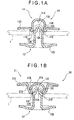
- Fig. 1A is a cross section of a button according to a first embodiment of the present invention and Fig. 1B is a cross section of a button according to a second embodiment;
- Fig. 2A is a cross section showing a state in which the button according to the first embodiment is attached to a fabric, and Fig. 2B is a cross section showing a state in which the button according to the second embodiment is attached to a fabric;
- Figs. 3A and 3B are cross sections respectively showing buttons according to modifications of the present invention;
- Figs. 4A to 4D are illustrations respectively showing different related arts; and
- Figs. 5A to 5B are illustrations showing related arts different from those in the Figs. 4A to 4D.
-
- Embodiments of the present invention will be described below with reference to the attached drawings. The present embodiment is applied to jeans and other garments as a decorative button.
- Fig. 1A is a cross section showing a first embodiment.
- In Fig. 1A, a
button 10 has abutton body 11 and afixture 12 attached to each other with afabric 1 interposed therebetween. - The
button body 11 is called F-bar and has a structure identical to the button body shown in Fig. 4B. Thebutton body 11 is made of aluminum, iron, stainless steel alloy, copper alloy including brass or other kind of metals or alloys by an appropriate processing such as press working. - The
button body 11 has a structure in which acenter portion 11B provided with aconcave portion 11A as a housing, a foldedportion 11C slightly folded back from an edge of an opening end as an insertion end of thecenter portion 11B, aflange 11D extending straight from the foldedportion 11C toward the outside are integrally molded. - The
center portion 11B is formed to have a cylindrical shape with a bottom face, and the inner side thereof is theconcave portion 11A. Theconcave portion 11A has a substantially rectangular shape with its openingend 11E rounded by appropriate curvature. - The folded
portion 11C is inverted from thecenter portion 11B, and theflange 11D extends at approximately square angle from an end of the foldedportion 11C. Theflange 11D is formed to have a substantially widened-ring shape. - The
fixture 12, as well as thebutton body 11, is made of aluminum, iron, stainless steel alloy, copper alloy including brass or other kind of metals or alloys by an appropriate processing such as press working. - The
fixture 12 has a structure in which atip end 12A having a substantially disk-shaped and inserted into theconcave portion 11A, atubular portion 12B having a substantially cylindrical shape and formed continuously from the tip end 12A, ashoulder 12C formed between the tip end 12A and thetubular portion 12B and aflange 12D having a substantially widened-ring shape and formed continuously from an end of thetubular portion 12B are integrally molded. - The
tip end 12A has aprojection 12E at the center thereof, which has a cylindrical shape with a bottom face and projects toward theconcave portion 11A. Theprojection 12E is adapted to be dented when pressed by thebutton body 11. Since thefixture 12 functions as a rivet, when theprojection 12E is dented to be lower than a flat portion of thetip end 12A, the whole part of the tip end 12A bulges outwardly. Then, the bulgedtip end 12A presses lateral side of theconcave portion 11A to engage. (Fig. 2A) - The
flange 12D is gradually inclined toward thebutton body 11 at the part closer to the outer periphery. - The
shoulder 12C has anedge 12F formed continuously on its circumference of the outer periphery, and theedge 12F forms a cutting portion to cut thefabric 1 with the openingend 11E of theconcave portion 11A of thebutton body 11. Here, the curvature radius R of theedge 12F is 0.5 mm or less, more preferably 0.3 mm or less. The smaller curvature radius R is more preferable, but the present embodiment employs 0.3 mm to 0.2 mm. The outer diameter of theedge 12F is formed to be same as or little smaller relative to the inner diameter of the openingend 11E of theconcave portion 11A. - The
shoulder 12C has an outer periphery radially bulged relative to thetubular portion 12B. - In order to attach the
button 10 of the first embodiment with the above structure to thefabric 1, thefabric 1 is interposed between thebutton body 11 and thefixture 12, and thetip end 12A of thefixture 12 is pressed against and inserted into theconcave portion 11A of thebutton body 11. - The
fabric 1 is cut between theedge 12F formed on theshoulder 12C and the openingend 11E of theconcave portion 11A of thebutton body 11 while being pressed and stretched by theprojection 12E of thetip end 12A of thefixture 12. - When the
tip end 12A is pressed against theconcave portion 11A, theprojection 12E is dented to be lower than a flat portion of thetip end 12A as shown in Fig. 2A, and thus the tip end 12A and the whole part of thetubular portion 12B are bulged outwardly so that it is pressed against and engaged with the lateral side of theconcave portion 11A. - Therefore, in the first embodiment, the following advantages can be obtained.
- (1) The
button body 11 has theconcave portion 11A for thetip end 12A of thefixture 12 to be inserted therein, and thefixture 12 has theshoulder 12C between the tip end 12A and thetubular portion 12B formed continuously from thetip end 12A. Theshoulder 12C has theedge 12F as a cutting portion to cut thefabric 1 with the openingend 11E of theconcave portion 11A of thebutton body 11. Therefore, even when a big force is applied to theedge 12F, theshoulder 12C is not broken due to its sufficient thickness, so that the fabric can be cut easily regardless of the thickness of the fabric. Further, since thebutton body 11 has a shape with theconcave portion 11A therein, F-bar type button body can be used without making any changes. - (2) Since the cutting portion is the
edge 12F formed on theshoulder 12C, processing of the cutting portion can be facilitated, so that the fixture can be manufactured easily. - (3) Since the
shoulder 12C has the outer periphery radially bulged relative to thetubular portion 12B, theshoulder 12C is hardly deformed, and damage on thefixture 12 can be prevented more effectively. - (4) The
tip end 12A has theprojection 12E projecting from theshoulder 12C. Therefore, when thefabric 1 is cut between theedge 12F of thefixture 12 and the openingend 11E of theconcave portion 11A of thebutton body 11, theprojection 12E projecting from theshoulder 12C presses and stretches thefabric 1, so that thefabric 1 can be cut easily and smoothly without damaging theedge 12F as the cutting portion. - (5) The
projection 12E is dented when pressed against thebutton body 11 and thetip end 12A is bulged outwardly so that the bulgedtip end 12A is engaged with theconcave portion 11A. With such structure, the lateral side of the tip end 12A sufficiently presses the lateral side of theconcave portion 11A of thebutton body 11, and thus the detaching force (separation force) of the button can be improved. This prevents thebutton body 11 from unexpectedly coming off from thefixture 12. - (6) Since the flange of the fixture is made into a plate-shaped which is easy to
press a thinner fabric, the
edge 12F as the cutting portion and theprojection 12E can be provided even if it is processed from a plate, and thus the fabric can be cut easily. The thickness of the plate used as a material of the fixture should preferably be in the range of 0.2 mm to 1 mm, more preferably, 0.3 mm to 0.6 mm. -
- Next, a second embodiment of the present invention will be described. The second embodiment only differs in the structure of a button body, and the structure of the fixture is the same with the
fixture 12 of the first embodiment. In the description of the second embodiment, for the components identical to those in the first embodiment, the same numerals are attached to omit the description thereof. - The present embodiment is applied to a decorative button.
- Fig. 1B shows a cross section showing a second embodiment.
- In Fig. 1B, a
button 20 has abutton body 21 and thefixture 12 attached to each other with thefabric 1 interposed therebetween. - The
button body 21 is called F-bar and has the same structure as the button body shown in Fig. 4A. Thebutton body 21, as thebutton body 11 in the first embodiment, is made of aluminum, iron, stainless steel alloy, copper alloy including brass, or other kind of metals or alloys by an appropriate processing such as press working, and has a structure in which acenter portion 21B provided with aconcave portion 21A as a housing, a foldedportion 21C slightly folded back from an opening end of thecenter portion 21B and theflange 21D extending from the foldedportion 21C toward the outside are integrally molded. - The
center portion 21B is formed to have a cylindrical shape with a bottom face, and the inner side thereof is theconcave portion 21A. Theconcave portion 21A has a curved shape with its openingend 21E rounded by appropriate curvature. - The folded
portion 21C is inverted from thecenter portion 21B to extend to the vicinity of the top of thecenter portion 21B, and theflange 21D extends at approximately square angle from an end of the foldedportion 21C. Theflange 21D shapes like a widened ring. - In order to attach the
button 20 of the second embodiment with such structure to thefabric 1, thefabric 1 is interposed between thebutton body 21 and thefixture 12, and thetip end 12A of thefixture 12 is pressed against and inserted into theconcave portion 21A of thebutton body 21 as in the first embodiment. - Then, the
fabric 1 is cut between theedge 12F formed on theshoulder 12C and the openingend 21E of theconcave portion 21A of thebutton body 21 while being pressed and stretched by theprojection 12E of thetip end 12A of thefixture 12. - When the
tip end 12A is pressed against theconcave portion 21A, theprojection 12E is dented to be lower than the flat portion of thetip end 12A, and thus the whole part of thetip end 12A is bulged outwardly so that it is pressed against and engaged with the lateral side of theconcave portion 21A. - Therefore, in the second embodiment, advantages similar to (1) to (6) of the first embodiment can be obtained.
- Incidentally, the scope of the present invention is not restricted to the above-described embodiments, but includes modifications and improvements as long as an object of the present invention can be achieved.
- For instance, in the second embodiment, the housing is the
concave portion 21A and the insertion end is theopening end 21E, but the structures of the housing and the insertion portion are not limited to the embodiment. For instance, as shown in Fig. 3A, the housing of thebutton body 21 may have a shape with anopening 21G formed on the top thereof. In such case, aninsertion end 21H is an opening located opposite to theopening 21G. A numeral 30 denotes a button attaching tool. In the present invention, as shown in Fig. 3B, a structure in which ashell 12G is attached to theflange 12D of thefixture 12 may be employed. - In the above-described embodiments, applications for decorative buttons are exemplified. However, the present invention is for buttoning garments, and it may be applied to a button for practical use. Further, the button of the present invention may also be used for items other than garments.
- In the present invention, the
tubular portion 12B is not limited to a cylindrical shape, and a squared tubular portion shape may also be employed. - The cutting portion is not limited to the one formed continuously on the circumference of the
shoulder 12C, but the one formed intermittently may also be employed. In such case, by perforating thefabric 1 and pressing the cutting portion against thefabric 1, thefabric 1 can be cut.
Claims (6)
- A button comprising: a button body (11, 21); and a fixture (12), the fixture (12) being pressed and fixed with a fabric (1) interposed between the button body (11, 21) and the fixture (12), wherein
the button body (11, 21) has a housing (11A, 21A) for a tip end (12A) of the fixture (12) to be inserted therein, and
the fixture (12) has a shoulder (12C) between the tip end (12A) and a tubular portion (12B) formed continuously from the tip end (12A), the shoulder (12C) having a cutting portion to cut the fabric (1) with an insertion end (11E, 21E) of the housing (11A, 21A) of the button body (11, 21). - The button according to claim 1, wherein the cutting portion is an edge (12F) formed on the shoulder (12C).
- The button according to claim 1 or 2, wherein the cutting portion is formed continuously or intermittently on a circumference of the shoulder (12C).
- The button according to any of claims 1 to 3, wherein the shoulder (12C) has an outer periphery radially bulged relative to the tubular portion (12B).
- The button according to any of claims 1 to 4, wherein the tip end (12A) has a projection (12E) projecting from the shoulder (12C).
- The button according to any of claims 1 to 5, wherein the tip end (12A) is adapted to be dented and bulged outwardly when pressed by the button body (11, 21), so that the bulged tip end (12A) is engaged with the housing (11A, 21A).
Applications Claiming Priority (2)
| Application Number | Priority Date | Filing Date | Title |
|---|---|---|---|
| JP2004014499 | 2004-01-22 | ||
| JP2004014499A JP2005204911A (en) | 2004-01-22 | 2004-01-22 | button |
Publications (2)
| Publication Number | Publication Date |
|---|---|
| EP1557107A1 true EP1557107A1 (en) | 2005-07-27 |
| EP1557107B1 EP1557107B1 (en) | 2009-09-09 |
Family
ID=34631931
Family Applications (1)
| Application Number | Title | Priority Date | Filing Date |
|---|---|---|---|
| EP05250299A Expired - Lifetime EP1557107B1 (en) | 2004-01-22 | 2005-01-21 | Button |
Country Status (7)
| Country | Link |
|---|---|
| US (1) | US20050160562A1 (en) |
| EP (1) | EP1557107B1 (en) |
| JP (1) | JP2005204911A (en) |
| CN (1) | CN1644126B (en) |
| BR (1) | BRPI0500193A (en) |
| DE (1) | DE602005016475D1 (en) |
| ES (1) | ES2331137T3 (en) |
Families Citing this family (14)
| Publication number | Priority date | Publication date | Assignee | Title |
|---|---|---|---|---|
| JP4554657B2 (en) * | 2007-10-01 | 2010-09-29 | Ykk株式会社 | button |
| BRPI0922442A2 (en) * | 2008-12-11 | 2015-08-04 | Syngenta Participations Ag | Sugar cane transformation. |
| US20100175226A1 (en) * | 2009-01-12 | 2010-07-15 | Foo-Yuen Wong | Two-component tack button |
| EP2514334A1 (en) * | 2009-12-14 | 2012-10-24 | YKK Corporation | Button fastener and button structure |
| US9049904B2 (en) | 2010-02-26 | 2015-06-09 | Ykk Corporation | Button fastener, method for forming button fastener, eyelet, and method for forming eyelet |
| CN102318935A (en) * | 2011-07-22 | 2012-01-18 | 关伟成 | Metal button pedestal and manufacturing technology thereof |
| CN103763966B (en) * | 2011-09-02 | 2016-09-21 | Ykk株式会社 | Outer enclosure body, fixture, button and the fixing means of fixing object |
| JPWO2013042232A1 (en) * | 2011-09-21 | 2015-03-26 | Ykk株式会社 | Button body and button |
| CN103635114A (en) * | 2011-09-21 | 2014-03-12 | Ykk株式会社 | Button body and button |
| JP5447492B2 (en) * | 2011-11-25 | 2014-03-19 | トヨタ自動車株式会社 | Sealed battery |
| WO2016038666A1 (en) * | 2014-09-08 | 2016-03-17 | Ykk株式会社 | Rivet |
| CN110025088B (en) * | 2019-04-12 | 2021-12-03 | 深圳市松记钮扣制品有限公司 | Fastener for button universal for thin and thick cloth |
| US10983600B2 (en) * | 2019-08-13 | 2021-04-20 | Apple Inc. | Electronic devices with fabric buttons |
| TWI781403B (en) * | 2020-05-14 | 2022-10-21 | 美宸科技股份有限公司 | Fabric strain gauge, fabric pressure gauge, and smart clothing |
Citations (5)
| Publication number | Priority date | Publication date | Assignee | Title |
|---|---|---|---|---|
| FR1102092A (en) * | 1954-03-29 | 1955-10-17 | Successeurs De Bois & Chassand | Improvements to riveted buttons for fabrics and others |
| GB1491617A (en) * | 1975-07-04 | 1977-11-09 | Bengtsson Sigurd W | Fitting for example a button including a male and a female portion |
| FR2471154A1 (en) * | 1979-12-15 | 1981-06-19 | Schaeffer Homberg Gmbh | Riveted press-stud button for garment - receives and traps rivet end and has domed section with round-angled star shape brim |
| FR2553268A1 (en) * | 1983-10-13 | 1985-04-19 | Stocko France Sa | Automatic button, in particular a rivet-type button |
| EP0291651A1 (en) * | 1987-05-22 | 1988-11-23 | William Prym GmbH & Co. KG | Tack button with a hollow shank |
Family Cites Families (6)
| Publication number | Priority date | Publication date | Assignee | Title |
|---|---|---|---|---|
| US576759A (en) * | 1897-02-09 | Theophilus r | ||
| US631212A (en) * | 1897-11-05 | 1899-08-15 | Rudolph Hoermann | Button. |
| JPS5925208U (en) * | 1982-08-11 | 1984-02-16 | 日本ノ−シヨン工業株式会社 | clothing button |
| AU557267B2 (en) * | 1983-04-13 | 1986-12-18 | Nippon Notion Kogyo Co. Ltd. | Button |
| CN2364717Y (en) * | 1999-01-22 | 2000-02-23 | 力顿钮扣配件(深圳)有限公司 | Plastic-steel snap-fastener fastening structure |
| JP2001178505A (en) * | 1999-12-24 | 2001-07-03 | Ykk Corp | Button tack |
-
2004
- 2004-01-22 JP JP2004014499A patent/JP2005204911A/en active Pending
-
2005
- 2005-01-20 US US11/038,962 patent/US20050160562A1/en not_active Abandoned
- 2005-01-21 CN CN200510005616.9A patent/CN1644126B/en not_active Expired - Fee Related
- 2005-01-21 BR BR0500193-5A patent/BRPI0500193A/en not_active IP Right Cessation
- 2005-01-21 DE DE602005016475T patent/DE602005016475D1/en not_active Expired - Lifetime
- 2005-01-21 ES ES05250299T patent/ES2331137T3/en not_active Expired - Lifetime
- 2005-01-21 EP EP05250299A patent/EP1557107B1/en not_active Expired - Lifetime
Patent Citations (5)
| Publication number | Priority date | Publication date | Assignee | Title |
|---|---|---|---|---|
| FR1102092A (en) * | 1954-03-29 | 1955-10-17 | Successeurs De Bois & Chassand | Improvements to riveted buttons for fabrics and others |
| GB1491617A (en) * | 1975-07-04 | 1977-11-09 | Bengtsson Sigurd W | Fitting for example a button including a male and a female portion |
| FR2471154A1 (en) * | 1979-12-15 | 1981-06-19 | Schaeffer Homberg Gmbh | Riveted press-stud button for garment - receives and traps rivet end and has domed section with round-angled star shape brim |
| FR2553268A1 (en) * | 1983-10-13 | 1985-04-19 | Stocko France Sa | Automatic button, in particular a rivet-type button |
| EP0291651A1 (en) * | 1987-05-22 | 1988-11-23 | William Prym GmbH & Co. KG | Tack button with a hollow shank |
Also Published As
| Publication number | Publication date |
|---|---|
| CN1644126A (en) | 2005-07-27 |
| CN1644126B (en) | 2010-05-05 |
| US20050160562A1 (en) | 2005-07-28 |
| BRPI0500193A (en) | 2005-09-06 |
| EP1557107B1 (en) | 2009-09-09 |
| ES2331137T3 (en) | 2009-12-22 |
| DE602005016475D1 (en) | 2009-10-22 |
| JP2005204911A (en) | 2005-08-04 |
Similar Documents
| Publication | Publication Date | Title |
|---|---|---|
| EP1557107B1 (en) | Button | |
| US4512063A (en) | Button | |
| US4698881A (en) | Socket element assembly for snap fasteners | |
| EP2514334A1 (en) | Button fastener and button structure | |
| JP2002005145A (en) | Caulking nut and manufacturing method thereof | |
| JPH1132815A (en) | Snap button and its mounting method | |
| US4570307A (en) | Button having plate for deflecting an attaching tack | |
| US4571780A (en) | Button having attachment tack deformed by anvil | |
| JP3087254U (en) | Hidden fastener pull head structure | |
| JP5615848B2 (en) | button | |
| CN102413726B (en) | Button-mounting member | |
| EP0733315A1 (en) | Male component of press-stud particularly for items of clothing | |
| CN101401673B (en) | button | |
| EP1547482B1 (en) | Button | |
| JP5132490B2 (en) | Male snap | |
| GB2188827A (en) | Attaching buttons | |
| JP3029022U (en) | Bag and bag clasp | |
| KR200368816Y1 (en) | Metallic eyelet for snap fastener | |
| CN223323092U (en) | Easy-in and difficult-out four-in buckle | |
| JP3120864U (en) | Mounting structure for gripping part in pan | |
| JPS6310730Y2 (en) | ||
| JP3066832U (en) | Resin couple rivets | |
| US4627134A (en) | Ball-side piece of snap fastener | |
| JP2617304B2 (en) | Hatome | |
| JPH0852013A (en) | Earrings |
Legal Events
| Date | Code | Title | Description |
|---|---|---|---|
| PUAI | Public reference made under article 153(3) epc to a published international application that has entered the european phase |
Free format text: ORIGINAL CODE: 0009012 |
|
| 17P | Request for examination filed |
Effective date: 20050218 |
|
| AK | Designated contracting states |
Kind code of ref document: A1 Designated state(s): AT BE BG CH CY CZ DE DK EE ES FI FR GB GR HU IE IS IT LI LT LU MC NL PL PT RO SE SI SK TR |
|
| AX | Request for extension of the european patent |
Extension state: AL BA HR LV MK YU |
|
| AKX | Designation fees paid |
Designated state(s): DE ES FR GB IT TR |
|
| 17Q | First examination report despatched |
Effective date: 20070529 |
|
| GRAP | Despatch of communication of intention to grant a patent |
Free format text: ORIGINAL CODE: EPIDOSNIGR1 |
|
| GRAS | Grant fee paid |
Free format text: ORIGINAL CODE: EPIDOSNIGR3 |
|
| GRAA | (expected) grant |
Free format text: ORIGINAL CODE: 0009210 |
|
| AK | Designated contracting states |
Kind code of ref document: B1 Designated state(s): DE ES FR GB IT TR |
|
| REG | Reference to a national code |
Ref country code: GB Ref legal event code: FG4D |
|
| REF | Corresponds to: |
Ref document number: 602005016475 Country of ref document: DE Date of ref document: 20091022 Kind code of ref document: P |
|
| REG | Reference to a national code |
Ref country code: ES Ref legal event code: FG2A Ref document number: 2331137 Country of ref document: ES Kind code of ref document: T3 |
|
| PGFP | Annual fee paid to national office [announced via postgrant information from national office to epo] |
Ref country code: DE Payment date: 20100114 Year of fee payment: 6 |
|
| PLBE | No opposition filed within time limit |
Free format text: ORIGINAL CODE: 0009261 |
|
| STAA | Information on the status of an ep patent application or granted ep patent |
Free format text: STATUS: NO OPPOSITION FILED WITHIN TIME LIMIT |
|
| 26N | No opposition filed |
Effective date: 20100610 |
|
| GBPC | Gb: european patent ceased through non-payment of renewal fee |
Effective date: 20100121 |
|
| REG | Reference to a national code |
Ref country code: FR Ref legal event code: ST Effective date: 20100930 |
|
| PG25 | Lapsed in a contracting state [announced via postgrant information from national office to epo] |
Ref country code: FR Free format text: LAPSE BECAUSE OF NON-PAYMENT OF DUE FEES Effective date: 20100201 |
|
| PG25 | Lapsed in a contracting state [announced via postgrant information from national office to epo] |
Ref country code: GB Free format text: LAPSE BECAUSE OF NON-PAYMENT OF DUE FEES Effective date: 20100121 |
|
| REG | Reference to a national code |
Ref country code: ES Ref legal event code: FD2A Effective date: 20110325 |
|
| PG25 | Lapsed in a contracting state [announced via postgrant information from national office to epo] |
Ref country code: ES Free format text: LAPSE BECAUSE OF NON-PAYMENT OF DUE FEES Effective date: 20110314 |
|
| PG25 | Lapsed in a contracting state [announced via postgrant information from national office to epo] |
Ref country code: ES Free format text: LAPSE BECAUSE OF NON-PAYMENT OF DUE FEES Effective date: 20100122 |
|
| REG | Reference to a national code |
Ref country code: DE Ref legal event code: R119 Ref document number: 602005016475 Country of ref document: DE Effective date: 20110802 |
|
| PG25 | Lapsed in a contracting state [announced via postgrant information from national office to epo] |
Ref country code: DE Free format text: LAPSE BECAUSE OF NON-PAYMENT OF DUE FEES Effective date: 20110802 |
|
| PG25 | Lapsed in a contracting state [announced via postgrant information from national office to epo] |
Ref country code: TR Free format text: LAPSE BECAUSE OF FAILURE TO SUBMIT A TRANSLATION OF THE DESCRIPTION OR TO PAY THE FEE WITHIN THE PRESCRIBED TIME-LIMIT Effective date: 20090909 |
|
| PGFP | Annual fee paid to national office [announced via postgrant information from national office to epo] |
Ref country code: IT Payment date: 20211213 Year of fee payment: 18 |
|
| PG25 | Lapsed in a contracting state [announced via postgrant information from national office to epo] |
Ref country code: IT Free format text: LAPSE BECAUSE OF NON-PAYMENT OF DUE FEES Effective date: 20230121 |