EP1556199B1 - Modular construction water flow guide for underwater pelletizer - Google Patents
Modular construction water flow guide for underwater pelletizer Download PDFInfo
- Publication number
- EP1556199B1 EP1556199B1 EP03779392A EP03779392A EP1556199B1 EP 1556199 B1 EP1556199 B1 EP 1556199B1 EP 03779392 A EP03779392 A EP 03779392A EP 03779392 A EP03779392 A EP 03779392A EP 1556199 B1 EP1556199 B1 EP 1556199B1
- Authority
- EP
- European Patent Office
- Prior art keywords
- flow guide
- water
- water flow
- sections
- axial
- Prior art date
- Legal status (The legal status is an assumption and is not a legal conclusion. Google has not performed a legal analysis and makes no representation as to the accuracy of the status listed.)
- Expired - Lifetime
Links
- XLYOFNOQVPJJNP-UHFFFAOYSA-N water Substances O XLYOFNOQVPJJNP-UHFFFAOYSA-N 0.000 title claims abstract description 156
- 238000010276 construction Methods 0.000 title description 4
- 239000008188 pellet Substances 0.000 claims abstract description 41
- 238000005520 cutting process Methods 0.000 claims description 32
- 229920000642 polymer Polymers 0.000 claims description 15
- 239000002002 slurry Substances 0.000 claims description 15
- 238000000034 method Methods 0.000 abstract description 4
- 238000007710 freezing Methods 0.000 abstract description 2
- 230000008014 freezing Effects 0.000 abstract description 2
- 239000012530 fluid Substances 0.000 abstract 1
- 238000005453 pelletization Methods 0.000 description 5
- 238000001816 cooling Methods 0.000 description 4
- 238000009826 distribution Methods 0.000 description 3
- 230000000694 effects Effects 0.000 description 3
- 230000003247 decreasing effect Effects 0.000 description 2
- 238000004519 manufacturing process Methods 0.000 description 2
- 238000009825 accumulation Methods 0.000 description 1
- 230000015572 biosynthetic process Effects 0.000 description 1
- 239000000498 cooling water Substances 0.000 description 1
- 230000006866 deterioration Effects 0.000 description 1
- 238000001035 drying Methods 0.000 description 1
- 238000001125 extrusion Methods 0.000 description 1
- 230000005923 long-lasting effect Effects 0.000 description 1
- 238000012856 packing Methods 0.000 description 1
- 238000005086 pumping Methods 0.000 description 1
- 238000010791 quenching Methods 0.000 description 1
- 238000010008 shearing Methods 0.000 description 1
- 229910001220 stainless steel Inorganic materials 0.000 description 1
- 239000010935 stainless steel Substances 0.000 description 1
Images


Classifications
-
- B—PERFORMING OPERATIONS; TRANSPORTING
- B29—WORKING OF PLASTICS; WORKING OF SUBSTANCES IN A PLASTIC STATE IN GENERAL
- B29B—PREPARATION OR PRETREATMENT OF THE MATERIAL TO BE SHAPED; MAKING GRANULES OR PREFORMS; RECOVERY OF PLASTICS OR OTHER CONSTITUENTS OF WASTE MATERIAL CONTAINING PLASTICS
- B29B9/00—Making granules
- B29B9/02—Making granules by dividing preformed material
- B29B9/06—Making granules by dividing preformed material in the form of filamentary material, e.g. combined with extrusion
- B29B9/065—Making granules by dividing preformed material in the form of filamentary material, e.g. combined with extrusion under-water, e.g. underwater pelletizers
-
- Y—GENERAL TAGGING OF NEW TECHNOLOGICAL DEVELOPMENTS; GENERAL TAGGING OF CROSS-SECTIONAL TECHNOLOGIES SPANNING OVER SEVERAL SECTIONS OF THE IPC; TECHNICAL SUBJECTS COVERED BY FORMER USPC CROSS-REFERENCE ART COLLECTIONS [XRACs] AND DIGESTS
- Y10—TECHNICAL SUBJECTS COVERED BY FORMER USPC
- Y10S—TECHNICAL SUBJECTS COVERED BY FORMER USPC CROSS-REFERENCE ART COLLECTIONS [XRACs] AND DIGESTS
- Y10S425/00—Plastic article or earthenware shaping or treating: apparatus
- Y10S425/23—Hay wafering or pelletizing means
Definitions
- the present invention generally relates to improvements in underwater pelletizers and more particularly to providing a sectioned adjustable water flow guide for the water box of an underwater pelletizer to more effectively adapt the conditions associated with the pressurized water flowing through the water box to the particular process requirements.
- the present invention provides for adjustability of the one-piece water flow guide disclosed in my co-pending application, Serial No. 09/400,287, filed September 21, 1999, and issued as U.S. Patent No. 6,551,087 on April 22, 2003, which is owned by the same assignee as the instant application.
- the flow guide in U.S. Patent No. 6,551,087 is shown positioned in a typical Model 6 pelletizer of assignee.
- the subject matter of U.S. Patent No. 6,551,087 corresponds with that of WO 01/21371.
- Underwater pelletizers are well known and include a die plate with multiple orifices through which molten polymer strands are extruded with the orifices terminating at a die face on the die plate.
- a powered rotary cutter including a cutter hub mounted on a shaft with a plurality of blades supported from the cutter hub is associated with the die face for shearing the extruded polymer strands into pellets as the polymer is extruded beyond the die face.
- a water box encloses the die face, cutter hub and blades to form a cutting chamber through which water flows to quench and rigidify the extruded polymer strands, thus enabling the cutting blades to better shear the extruded strands into pellets.
- the flow of water through the cutting chamber defined by the water box also conveys a slurry of the water and sheared pellets through the outlet of the water box to a pellet dewaterer and/or a dryer.
- the above described underwater pelletizers are disclosed in related U.S. patents including U.S. Patent Nos. 4,123,207, 4,251,198, 4,621,996, 4,728,276 and 5,059,103, all owned by the assignee of this invention.
- Another object of the present invention is to provide an adjustable water flow guide that optimizes pellet distribution and generates satisfactory head pressure against the pellets through water flow control.
- a further object of the present invention is to provide a sectioned water flow guide stationarily positioned in the cutting chamber of an underwater pelletizer that can be adjusted to effectively vary the amount of cutting chamber space for successful pellet generation.
- Still another object of the present invention is to provide a water flow guide that directs water to the seal area and, through circulation within the internal flow guide chamber, eliminates fines incoming thereto, pumping such fines immediately out of the seal area to prevent interference with the rotating shaft.
- a still further object of the present invention is to provide a water flow guide made of multiple interchangeable sections which, through selection of the number and thickness of the sections used, can effectively accommodate a broad range of melt temperatures, pellet sizes, cutter speeds and water temperatures in the pelletizing operation.
- Yet another object of this invention to be specifically enumerated herein is to provide a water flow guide in accordance with the preceding objects which will conform to conventional forms of manufacture, be of simple construction and easy to use so as to provide a device that will be economically feasible, long lasting and relatively trouble free in operation.
- the water flow guide of the present invention is sectioned and thus adjustable in length so that, when positioned within the cutting chamber defined by the water box of an underwater pelletizer, the flow of pressurized water passing through the water box can be changed in accordance with the adjusted size selected for the water flow guide.
- the overall length of the flow guide can be selectively modified, and the amount and rate of water allowed to flow past the face of the die plate is adjusted.
- the water flow guide of this invention is stationarily mounted within the cutting chamber, preferably on the front of the pelletizer, and is oriented in the cutting chamber between the water inlet and the water and pellet slurry outlet of the water box, which are typically disposed in diametrically opposed relation, such as a water inlet at the bottom of the cutting chamber and the water and pellet slurry outlet at the top.
- the adjustability of the water flow guide can produce a range of pressurized water flows and effectively direct a specified volume of cooling water toward the die face and the polymer strands being extruded therefrom. By varying the distance between the cutting blades and the flow guide to direct and control the water flow to the die face, excessive cooling of the polymer and associated distortion of the pellets is prevented.
- the adjustable water flow guide of the present invention optimizes pellet distribution, improves the initial cooling effect of the pellets, and generates satisfactory head pressure against the pellets, allowing the flow of water across the face of the die plate to be optimized in accordance with the needs of specific pelletizing applications.
- the water flow guide is in the form of a cylindrical tubular member affixed to the pelletizer in generally concentric relation to the rotating shaft of the pelletizer, preferably with the body of the guide filling out the majority of the cutting chamber volume.
- the tubular member includes a generally cylindrical axial bore which is positioned over and surrounds the rotating cutting hub shaft forming an annular space therebetween.
- the free end of the guide's tubular member preferably terminates adjacent to the rotating cutter hub and cutting blades mounted thereon.
- the water flow guide is a generally cylindrical tubular member with the external surface thereof being disposed adjacent to the generally cylindrical inner surface of the water box. Between the tubular member and the pelletizer, a variable number of annular sections can be positioned to adjust the overall length of the flow guide and thereby alter the flow volume passing over the face of the die plate for any particular application.
- the generally cylindrical tubular member is made up of a plurality of sections which together form the water flow guide.
- the outer wall is preferably sized to be only slightly smaller than the inner wall of the water box to provide a very small clearance between the adjacent surfaces.
- Each section is machined to fit in close abutment with its adjacent section or sections and, when joined, the sections create a cylindrical outer surface that includes diametrically opposed, axially extending recesses, with one recess in alignment with the water inlet and the other recess in alignment with the slurry outlet of the water box.
- One end of each of the axial recesses is spaced between the ends of the cylindrical surface and in registry with the water inlet and slurry outlet, respectively.
- each of the axial recesses opens to a free end of the water flow guide which terminates facing the cutter hub and cutter blades.
- Sections of different thicknesses may be employed to adjust the overall length of the flow guide and the axial recesses.
- the axial recess portion of each section is properly machined to retain the continuity of the desired overall axial recess when the sections are adjoined.
- the water flow guide again includes the generally tubular cylindrical member formed of sections as described in the second embodiment.
- the tubular member is formed of a plurality of annular flat plates that are bolted together. Because there are no recesses machined therein, this embodiment has simplified manufacturing requirements, while still effectively providing a means for adjusting water flow through the cutting chamber.
- the adjustability of the flow guide enables a wider range of water temperatures, melt temperatures, flow rates and pellet sizes to be accommodated simply by selecting the desired flow guide components.
- FIGS 1-3 illustrate a water flow guide, generally designated by reference numeral 10, associated with an underwater pelletizer, generally designated by reference numeral 12.
- the underwater pelletizer 12 such as that disclosed in U.S. Patent No. 5,059,103, is a typical Model 7 pelletizer manufactured by the assignee of this application.
- the pelletizer 12 is schematically illustrated and includes a die plate 14 having a plurality of die orifices 16 therein through which molten polymer is extruded into strands which pass through a die face 18 on the inner surface of the die plate 14.
- the die plate 14 is connected to a pelletizer water box, generally designated by reference numeral 20, which includes a cutting chamber 22 and also includes a pressurized water inlet 24 and a diametrically opposed outlet 26 for discharge of a slurry of water and pellets from the cutting chamber 22 for conveyance out of the water box 20 to a pellet dewaterer and/or a pellet dryer (not shown).
- the pelletizer 12 includes a motor 28 with an output shaft 30 drivingly connected to a cutter hub shaft 32 having a cutter hub 34 mounted thereon.
- the cutter hub 34 includes a plurality of radially extending support arms 36 which support replaceable cutter blades 37 which coact with the die face 18 to shear the extruded strands of polymer into pellets. Except for the water flow guide 10 of the present invention, the structure of the underwater pelletizer may correspond generally with that disclosed in U.S. Patent No. 5,059,103.
- the typical underwater pelletizer utilizes water to cool and rigidify the strands of polymer as they are discharged from the die face, with the spacing of the cutter blades and the rotational speed of the cutter hub determining the size of pellets sheared from the extruded polymer strands. Water flowing in through the water inlet not only cools and rigidifies the polymer strands but also conveys the sheared pellets as a slurry from the cutting chamber into the outlet.
- the water flow guide 10 of the present invention guides the inlet water from inlet 24 toward the die plate 14 so that it moves along the surface of the die face 18 and over and around the rotating cutter hub 34 and cutter blades 37.
- the cutting chamber space and selectively directing this water flow the extruded strands of polymer may be more efficiently quenched, thereby more effectively cooling and rigidifying the polymer strands.
- the size of the flow guide and thus the water flow space inside the cutting chamber the flow of too much water across the die face can be prevented, thereby reducing pellet distortion and die hole freezing.
- the water flow guide 10 also provides more effective entrainment of the pellets in the water and more effective conveyance of the water and pellet slurry through the flow path for discharge through outlet 26 from the water box 20 for subsequent dewatering and drying.
- the water flow guide illustrated in Figures 1-3 includes a generally cylindrical tubular member, generally designated by the reference numeral 38, having an outer surface 40 and a cylindrical axial bore 42 which is substantially concentric with and closely surrounds the cutter hub shaft 32 as illustrated in Figure 1, thus forming an annular space 43.
- Interchangeable annular sections 60, 62 are mounted to the pelletizer end of the cylindrical tubular member 38 which is furthest from the die plate. An outermost section 62 abuts and is secured against the seal holding plate 46 to which the flow guide is mounted.
- the seal holding plate 46 is provided with an annular rubber-type seal 44 which prevents inflow of the water circulating in the annular space 43 between the axial bore 42 and cutter hub shaft 32.
- the number of annular sections 60, 62 may be varied, as may the thickness of each section, to allow the overall length of the flow guide to be adjusted, thereby providing a means for increasing or decreasing the flow of water across the face of the die plate. When too much water flows across the die face, the pellets can become distorted and the die holes can freeze over.
- various numbers of annular sections e.g., one, two, three, etc., as well as the use of sections having different thicknesses, the water flow is increased or decreased according to specific application requirements. Because the annular sections may be readily manufactured out of stainless steel, the resulting flow guide also demonstrates reduced deterioration arising from pellet wear in the flow inlet and outlet, extending the useful life of the flow guide.
- the free end 48 of the tubular member 38 is flat with a tapered or beveled edge 56 around its periphery.
- the free end 48 terminates adjacent the cutter blades 37 on the cutter hub 34.
- a plurality of longitudinally extending through-bolts 50 are countersunk into the flat surface 48 of the tubular member 38 and extend therethrough and through the annular sections 60, 62 to screw thread into the seal holding plate 46 of the pelletizer structure. Bolts of different lengths may be employed depending upon the number of annular sections inserted between the flow guide and the pelletizer.
- the tubular cylindrical member 38 with the annular sections 60, 62 is rigidly affixed to the pelletizer and is oriented in concentric relation to the cutter hub shaft 32, with the external surface 40 adjacent the interior surface of the cutting chamber 22.
- the external surface 40 of the tubular member 38 includes diametrically opposed longitudinally extending grooves or recesses 52 which are arcuate in transverse configuration.
- the grooves or recesses 52 are in alignment with the diametrically opposed water inlet 24 and slurry outlet 26, respectively.
- the inner end of each recess 52 is preferably arcuately curved at 54 so that the outer edge of the upwardly curved inner end coincides with the interior surface of the aligned edge of each the water inlet 24 and the slurry outlet 26, respectively.
- the outer end of each recess terminates at the free outer end 48 and beveled edge surface 56 which faces the rotational path of the cutter blades 37, as illustrated in Figures 1 and 3.
- Other recess formation and passageway designs may be machined into the various sections, such as those shown and described in my aforesaid U.S. Patent No. 6,551,087.
- the external surface 40 of the guide is closely adjacent or engaging the internal surface of the cutting chamber 22 and the free end 48 is closely adjacent the cutter hub 34 and cutter blades 37 with sufficient clearance not to interfere with their rotation.
- the guide 10 preferably fills the whole cutting chamber 22.
- the close fitting relationship of the water flow guide 10 in relation to the water box 20 and cutting chamber 22 assures that incoming pressurized water will engage the axial recess 52 in alignment with the water inlet 24, causing the water to move axially toward the die face 18, the cutter hub 34, cutter hub arms 36 and cutter blades 37, and then transversely across the die face 18 and around the cutter hub assembly.
- the transverse flow of water across the die face 18 may be optimized for any given pelletizing application and pellet size.
- the design of the water flow guide also facilitates water flow through the annular space or chamber 43, moving incoming fines out of the area adjacent the seal 44, to prevent such fines from packing into the annular space 43 around the shaft 32.
- FIGS 4A and 4B illustrate a variant of the water flow guide shown in Figures 1-3, generally designated by the reference numeral 70.
- Flow guide 70 includes tubular member 72 having an internal axial bore 74, an external axial recess 76 for alignment with pressurized water inlet and a diametrically opposed external axial recess 78 for alignment with a water and pellet slurry outlet.
- the free end of the water flow guide 70 is provided with opposing beveled or sloped edge surfaces 80, and a tapering sloped relief 82 is provided on each edge surface 80 in opposing angular directions, to facilitate water flow.
- through-bolts 84 pass through apertures in the tubular member 72 and apertures 86 in the annular sections 88, 89 to mount the flow guide to the pelletizer in substantially the same position in the water box.
- FIGs 5A and 5B illustrate a second embodiment of the water flow guide, generally designated by the reference numeral 90, which includes a plurality of sections 92, 94, 96, 98 which are bolted together to form a tubular member as illustrated in Figure 5A.
- the rearwardmost section 98 is generally cylindrical without cutouts in its outer surface.
- the next adjacent section 96 has a generally spherical section cutout 107 to define the back end of axial grooves 110 which correspond to surface 54 and axial grooves 52, respectively, in the first embodiment.
- the two front sections 92, 94 have circular cutout openings 102, 104, respectively, which, when the sections are bolted together, mate with cutout 107 to form the axial grooves 110, as in the first embodiment.
- each of the sections 92, 94, 96 includes a pair of axial recesses 103, 105, 107, respectively, the recesses of each pair being in opposing relationship.
- axial recesses 103, 105 are substantially equal in size and shape
- axial recesses 107 are arcuately curved (spherical section shaped) so that the outer edge of the upwardly curved inner end coincides with the interior surface of the aligned edge of each of the water inlet 24 and the slurry outlet 26, respectively.
- each of sections 92, 94, 96 could include only one recess, or the sections could be manufactured without any recesses.
- Figure 6 depicts a cross-sectional view of a third embodiment of a water flow guide in accordance with the present invention, generally designated by the reference numeral 110, as mounted to an underwater pelletizer.
- the flow guide 110 is comprised of a plurality of sections, here annular flat plates 112, 114, 116, 118 that include generally oval openings 128 through which bolts may be inserted to secure the plates to each other and to the seal holding plate 120.
- the plates can be machined with inlet and outlet grooves on their outermost surfaces to direct the water flow or, as shown in Figure 6, can be made without grooves so as to be interchangeable.
- a holding plate seal 122 fits into a groove on the surface of the seal holding plate 120 to prevent entry of the water circulating within the annular space 124.
- Flow of water through the annular space 124 acts to move incoming fines immediately out of the seal area, preventing the accumulation of such fines around the shaft 33 which might otherwise interfere with the seal 122 and shaft 33 rotating therein.
- the nature and density of the fines define the final configuration of the flow guide and the desired spacing between axial bore wall 119 of the flow guide 110 and the pelletizer shaft 33.
- Varying numbers of plates may be included to adjust the overall length of the resulting flow guide. As can be seen, each additional plate narrows the inflow channel 24A for water flowing from the inlet 24 and the outflow channel 26A through which the slurry is directed, as well as the overall cutting chamber space. Varying the number of plates also enables the distance between the cutter hub holder and blades and the flow guide to be adjusted in order to optimize pellet distribution, improve the initial cooling effect of the water on the pellets and generate satisfactory head pressure against the pellets leaving the die holes.
- the adjustable flow guide greatly reduces the need for different water box designs in order to alter inlet and outlet flow configuration.
- the adjustable flow guide now provides a means of customization of water flow while using the same water box. Different effects may also be obtained with the same cutter hub design through adjustment in the flow guide.
- the present invention enables head pressure, which is the result of the design of the pelletizing system after the pellets are introduced into the water flow, to be adjusted across a broader range.
- the adjustable water flow guide enables important parameters including pipe dimension and length, height, extra pressure valve and water flow, also to be adjusted easily and efficiently.
Landscapes
- Engineering & Computer Science (AREA)
- Mechanical Engineering (AREA)
- Processing And Handling Of Plastics And Other Materials For Molding In General (AREA)
- Farming Of Fish And Shellfish (AREA)
- Catching Or Destruction (AREA)
- Feeding, Discharge, Calcimining, Fusing, And Gas-Generation Devices (AREA)
- Aeration Devices For Treatment Of Activated Polluted Sludge (AREA)
Abstract
Description
- The present invention generally relates to improvements in underwater pelletizers and more particularly to providing a sectioned adjustable water flow guide for the water box of an underwater pelletizer to more effectively adapt the conditions associated with the pressurized water flowing through the water box to the particular process requirements.
- The present invention provides for adjustability of the one-piece water flow guide disclosed in my co-pending application, Serial No. 09/400,287, filed September 21, 1999, and issued as U.S. Patent No. 6,551,087 on April 22, 2003, which is owned by the same assignee as the instant application. The flow guide in U.S. Patent No. 6,551,087 is shown positioned in a typical Model 6 pelletizer of assignee. The subject matter of U.S. Patent No. 6,551,087 corresponds with that of WO 01/21371.
- Underwater pelletizers are well known and include a die plate with multiple orifices through which molten polymer strands are extruded with the orifices terminating at a die face on the die plate. A powered rotary cutter including a cutter hub mounted on a shaft with a plurality of blades supported from the cutter hub is associated with the die face for shearing the extruded polymer strands into pellets as the polymer is extruded beyond the die face. A water box encloses the die face, cutter hub and blades to form a cutting chamber through which water flows to quench and rigidify the extruded polymer strands, thus enabling the cutting blades to better shear the extruded strands into pellets. The flow of water through the cutting chamber defined by the water box also conveys a slurry of the water and sheared pellets through the outlet of the water box to a pellet dewaterer and/or a dryer. The above described underwater pelletizers are disclosed in related U.S. patents including U.S. Patent Nos. 4,123,207, 4,251,198, 4,621,996, 4,728,276 and 5,059,103, all owned by the assignee of this invention.
- While the above listed patents disclose various structures associated with underwater pelletizers, a need exists for adjustability in guiding the water flow through the water box in accordance with the particular process requirements of an extrusion and pelletizing application without the need for changing the water box design or for a new water flow guide.
- Accordingly, it is an object of the present invention to provide a sectioned adjustable water flow guide positioned in the cutting chamber of an underwater pelletizer, with the sectioned water flow guide being adjustable to vary the volume of pressurized water flow into the water inlet, axially toward the die face and then with the sheared pellets away from the die face and to the outlet.
- Another object of the present invention is to provide an adjustable water flow guide that optimizes pellet distribution and generates satisfactory head pressure against the pellets through water flow control.
- A further object of the present invention is to provide a sectioned water flow guide stationarily positioned in the cutting chamber of an underwater pelletizer that can be adjusted to effectively vary the amount of cutting chamber space for successful pellet generation.
- Still another object of the present invention is to provide a water flow guide that directs water to the seal area and, through circulation within the internal flow guide chamber, eliminates fines incoming thereto, pumping such fines immediately out of the seal area to prevent interference with the rotating shaft.
- A still further object of the present invention is to provide a water flow guide made of multiple interchangeable sections which, through selection of the number and thickness of the sections used, can effectively accommodate a broad range of melt temperatures, pellet sizes, cutter speeds and water temperatures in the pelletizing operation.
- Yet another object of this invention to be specifically enumerated herein is to provide a water flow guide in accordance with the preceding objects which will conform to conventional forms of manufacture, be of simple construction and easy to use so as to provide a device that will be economically feasible, long lasting and relatively trouble free in operation.
- In accordance with these and other objects, the water flow guide of the present invention is sectioned and thus adjustable in length so that, when positioned within the cutting chamber defined by the water box of an underwater pelletizer, the flow of pressurized water passing through the water box can be changed in accordance with the adjusted size selected for the water flow guide. By selecting the appropriate flow guide sections the overall length of the flow guide can be selectively modified, and the amount and rate of water allowed to flow past the face of the die plate is adjusted.
- The water flow guide of this invention is stationarily mounted within the cutting chamber, preferably on the front of the pelletizer, and is oriented in the cutting chamber between the water inlet and the water and pellet slurry outlet of the water box, which are typically disposed in diametrically opposed relation, such as a water inlet at the bottom of the cutting chamber and the water and pellet slurry outlet at the top. The adjustability of the water flow guide can produce a range of pressurized water flows and effectively direct a specified volume of cooling water toward the die face and the polymer strands being extruded therefrom. By varying the distance between the cutting blades and the flow guide to direct and control the water flow to the die face, excessive cooling of the polymer and associated distortion of the pellets is prevented. The adjustable water flow guide of the present invention optimizes pellet distribution, improves the initial cooling effect of the pellets, and generates satisfactory head pressure against the pellets, allowing the flow of water across the face of the die plate to be optimized in accordance with the needs of specific pelletizing applications.
- The water flow guide is in the form of a cylindrical tubular member affixed to the pelletizer in generally concentric relation to the rotating shaft of the pelletizer, preferably with the body of the guide filling out the majority of the cutting chamber volume. The tubular member includes a generally cylindrical axial bore which is positioned over and surrounds the rotating cutting hub shaft forming an annular space therebetween. The free end of the guide's tubular member preferably terminates adjacent to the rotating cutter hub and cutting blades mounted thereon. Such a construction is like that shown in aforesaid U.S. Patent No. 6,551,087.
- According to a first embodiment of the present invention, the water flow guide is a generally cylindrical tubular member with the external surface thereof being disposed adjacent to the generally cylindrical inner surface of the water box. Between the tubular member and the pelletizer, a variable number of annular sections can be positioned to adjust the overall length of the flow guide and thereby alter the flow volume passing over the face of the die plate for any particular application.
- In a second embodiment of the invention, the generally cylindrical tubular member is made up of a plurality of sections which together form the water flow guide. Again, the outer wall is preferably sized to be only slightly smaller than the inner wall of the water box to provide a very small clearance between the adjacent surfaces. Each section is machined to fit in close abutment with its adjacent section or sections and, when joined, the sections create a cylindrical outer surface that includes diametrically opposed, axially extending recesses, with one recess in alignment with the water inlet and the other recess in alignment with the slurry outlet of the water box. One end of each of the axial recesses is spaced between the ends of the cylindrical surface and in registry with the water inlet and slurry outlet, respectively. The other end of each of the axial recesses opens to a free end of the water flow guide which terminates facing the cutter hub and cutter blades. Sections of different thicknesses may be employed to adjust the overall length of the flow guide and the axial recesses. The axial recess portion of each section is properly machined to retain the continuity of the desired overall axial recess when the sections are adjoined.
- In a third embodiment of the invention, the water flow guide again includes the generally tubular cylindrical member formed of sections as described in the second embodiment. In this embodiment, however, the tubular member is formed of a plurality of annular flat plates that are bolted together. Because there are no recesses machined therein, this embodiment has simplified manufacturing requirements, while still effectively providing a means for adjusting water flow through the cutting chamber.
- In each embodiment of the invention, the adjustability of the flow guide enables a wider range of water temperatures, melt temperatures, flow rates and pellet sizes to be accommodated simply by selecting the desired flow guide components.
- These together with other objects and advantages which will become subsequently apparent reside in the details of construction and operation as more fully hereinafter described and claimed, reference being had to the accompanying drawings forming a part hereof, wherein like numerals refer to like parts throughout.
-
- Figure 1 is a vertical, longitudinal sectional view of an underwater pelletizer having one embodiment of a water flow guide with annular sections positioned therein in accordance with the present invention, and illustrating the water flow path through the cutting chamber.
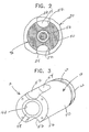
- Figure 2 is a transverse, vertical sectional view along section line 2-2 in Figure 1 illustrating the association of the water flow guide to the water box, pelletizer drive shaft, cutter hub, water inlet and water and slurry outlet.
- Figure 3 is a perspective view of the water flow guide with annular sections shown in Figures 1 and 2 looking at the end adjacent the die plate, cutter hub and cutter blades.
- Figure 4A is a perspective view of a variant of the water flow guide with annular sections of Figures 1-3.
- Figure 4B is an exploded view of the annular sections and variant water flow guide shown in Figure 4A.
- Figure 5A is a second embodiment of a flow guide in accordance with the present invention, the flow guide formed of multiple adjoining sections.
- Figure 5B is an exploded view of the multiple section water flow guide shown in Figure 5A.
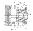
- Figure 6 is a vertical longitudinal sectional view of an underwater pelletizer having a third embodiment of an adjustable water flow guide mounted in accordance with the present invention.
- Figures 1-3 illustrate a water flow guide, generally designated by
reference numeral 10, associated with an underwater pelletizer, generally designated by reference numeral 12. The underwater pelletizer 12, such as that disclosed in U.S. Patent No. 5,059,103, is a typical Model 7 pelletizer manufactured by the assignee of this application. The pelletizer 12 is schematically illustrated and includes adie plate 14 having a plurality of die orifices 16 therein through which molten polymer is extruded into strands which pass through adie face 18 on the inner surface of thedie plate 14. Thedie plate 14 is connected to a pelletizer water box, generally designated by reference numeral 20, which includes acutting chamber 22 and also includes a pressurizedwater inlet 24 and a diametrically opposedoutlet 26 for discharge of a slurry of water and pellets from thecutting chamber 22 for conveyance out of the water box 20 to a pellet dewaterer and/or a pellet dryer (not shown). The pelletizer 12 includes a motor 28 with anoutput shaft 30 drivingly connected to acutter hub shaft 32 having acutter hub 34 mounted thereon. Thecutter hub 34 includes a plurality of radially extendingsupport arms 36 which supportreplaceable cutter blades 37 which coact with thedie face 18 to shear the extruded strands of polymer into pellets. Except for thewater flow guide 10 of the present invention, the structure of the underwater pelletizer may correspond generally with that disclosed in U.S. Patent No. 5,059,103. - The typical underwater pelletizer utilizes water to cool and rigidify the strands of polymer as they are discharged from the die face, with the spacing of the cutter blades and the rotational speed of the cutter hub determining the size of pellets sheared from the extruded polymer strands. Water flowing in through the water inlet not only cools and rigidifies the polymer strands but also conveys the sheared pellets as a slurry from the cutting chamber into the outlet.
- As shown by the arrows 51 and 53 in Figure 1, the water flow guide 10 of the present invention guides the inlet water from
inlet 24 toward thedie plate 14 so that it moves along the surface of thedie face 18 and over and around therotating cutter hub 34 andcutter blades 37. By adjusting the cutting chamber space and selectively directing this water flow, the extruded strands of polymer may be more efficiently quenched, thereby more effectively cooling and rigidifying the polymer strands. By adjusting the size of the flow guide and thus the water flow space inside the cutting chamber, the flow of too much water across the die face can be prevented, thereby reducing pellet distortion and die hole freezing. As a result, therotating cutter blades 37 more effectively shear the extruded strands to form pellets by making a substantially straight diametric cut through the polymer strands. Thewater flow guide 10 also provides more effective entrainment of the pellets in the water and more effective conveyance of the water and pellet slurry through the flow path for discharge throughoutlet 26 from the water box 20 for subsequent dewatering and drying. - The water flow guide illustrated in Figures 1-3 includes a generally cylindrical tubular member, generally designated by the
reference numeral 38, having anouter surface 40 and a cylindrical axial bore 42 which is substantially concentric with and closely surrounds thecutter hub shaft 32 as illustrated in Figure 1, thus forming anannular space 43. Interchangeableannular sections cylindrical tubular member 38 which is furthest from the die plate. Anoutermost section 62 abuts and is secured against theseal holding plate 46 to which the flow guide is mounted. Theseal holding plate 46 is provided with an annular rubber-type seal 44 which prevents inflow of the water circulating in theannular space 43 between theaxial bore 42 andcutter hub shaft 32. - The number of
annular sections - The
free end 48 of thetubular member 38, nearest the die face, is flat with a tapered orbeveled edge 56 around its periphery. Thefree end 48 terminates adjacent thecutter blades 37 on thecutter hub 34. A plurality of longitudinally extending through-bolts 50 are countersunk into theflat surface 48 of thetubular member 38 and extend therethrough and through theannular sections seal holding plate 46 of the pelletizer structure. Bolts of different lengths may be employed depending upon the number of annular sections inserted between the flow guide and the pelletizer. In this way, the tubularcylindrical member 38 with theannular sections cutter hub shaft 32, with theexternal surface 40 adjacent the interior surface of the cuttingchamber 22. - The
external surface 40 of thetubular member 38 includes diametrically opposed longitudinally extending grooves or recesses 52 which are arcuate in transverse configuration. The grooves or recesses 52 are in alignment with the diametricallyopposed water inlet 24 andslurry outlet 26, respectively. The inner end of eachrecess 52 is preferably arcuately curved at 54 so that the outer edge of the upwardly curved inner end coincides with the interior surface of the aligned edge of each thewater inlet 24 and theslurry outlet 26, respectively. The outer end of each recess terminates at the freeouter end 48 and bevelededge surface 56 which faces the rotational path of thecutter blades 37, as illustrated in Figures 1 and 3. Other recess formation and passageway designs may be machined into the various sections, such as those shown and described in my aforesaid U.S. Patent No. 6,551,087. - Preferably, the
external surface 40 of the guide is closely adjacent or engaging the internal surface of the cuttingchamber 22 and thefree end 48 is closely adjacent thecutter hub 34 andcutter blades 37 with sufficient clearance not to interfere with their rotation. Thus, except for the selectively designated water flow paths defined byrecesses 52, and the space around thedie plate 18,cutter hub 34 andcutter blades 37, theguide 10 preferably fills thewhole cutting chamber 22. - As illustrated in Figure 2, the close fitting relationship of the water flow guide 10 in relation to the water box 20 and cutting
chamber 22 assures that incoming pressurized water will engage theaxial recess 52 in alignment with thewater inlet 24, causing the water to move axially toward thedie face 18, thecutter hub 34,cutter hub arms 36 andcutter blades 37, and then transversely across thedie face 18 and around the cutter hub assembly. Through selection of the appropriate number and thickness of additional annular sections, the transverse flow of water across thedie face 18 may be optimized for any given pelletizing application and pellet size. The design of the water flow guide also facilitates water flow through the annular space orchamber 43, moving incoming fines out of the area adjacent the seal 44, to prevent such fines from packing into theannular space 43 around theshaft 32. - Figures 4A and 4B illustrate a variant of the water flow guide shown in Figures 1-3, generally designated by the
reference numeral 70.Flow guide 70 includestubular member 72 having an internal axial bore 74, an externalaxial recess 76 for alignment with pressurized water inlet and a diametrically opposed externalaxial recess 78 for alignment with a water and pellet slurry outlet. The free end of thewater flow guide 70 is provided with opposing beveled or sloped edge surfaces 80, and a tapering slopedrelief 82 is provided on eachedge surface 80 in opposing angular directions, to facilitate water flow. As with the embodiment shown in Figure 1, through-bolts 84 pass through apertures in thetubular member 72 andapertures 86 in theannular sections - Figures 5A and 5B illustrate a second embodiment of the water flow guide, generally designated by the
reference numeral 90, which includes a plurality ofsections rearwardmost section 98 is generally cylindrical without cutouts in its outer surface. The next adjacent section 96 has a generallyspherical section cutout 107 to define the back end ofaxial grooves 110 which correspond to surface 54 andaxial grooves 52, respectively, in the first embodiment. The twofront sections circular cutout openings cutout 107 to form theaxial grooves 110, as in the first embodiment. - As can be seen in Figures 5A and 5B, each of the
sections axial recesses axial recesses axial recesses 107 are arcuately curved (spherical section shaped) so that the outer edge of the upwardly curved inner end coincides with the interior surface of the aligned edge of each of thewater inlet 24 and theslurry outlet 26, respectively. Alternatively, each ofsections - Figure 6 depicts a cross-sectional view of a third embodiment of a water flow guide in accordance with the present invention, generally designated by the
reference numeral 110, as mounted to an underwater pelletizer. As with the second embodiment, theflow guide 110 is comprised of a plurality of sections, here annularflat plates oval openings 128 through which bolts may be inserted to secure the plates to each other and to theseal holding plate 120. The plates can be machined with inlet and outlet grooves on their outermost surfaces to direct the water flow or, as shown in Figure 6, can be made without grooves so as to be interchangeable. - A holding
plate seal 122 fits into a groove on the surface of theseal holding plate 120 to prevent entry of the water circulating within theannular space 124. Flow of water through theannular space 124 acts to move incoming fines immediately out of the seal area, preventing the accumulation of such fines around theshaft 33 which might otherwise interfere with theseal 122 andshaft 33 rotating therein. The nature and density of the fines define the final configuration of the flow guide and the desired spacing betweenaxial bore wall 119 of theflow guide 110 and thepelletizer shaft 33. - Varying numbers of plates may be included to adjust the overall length of the resulting flow guide. As can be seen, each additional plate narrows the
inflow channel 24A for water flowing from theinlet 24 and theoutflow channel 26A through which the slurry is directed, as well as the overall cutting chamber space. Varying the number of plates also enables the distance between the cutter hub holder and blades and the flow guide to be adjusted in order to optimize pellet distribution, improve the initial cooling effect of the water on the pellets and generate satisfactory head pressure against the pellets leaving the die holes. - With the present invention it is possible, with a single system and a single flow guide component, to fine tune the physics of the internal flow guide to best accommodate a range of process requirements. For example, water flow and temperature, as well as mass flow and melt temperature, may be adjusted cooperatively and over a wider range than is possible with prior designs. Conditions may be optimized for pellets of different sizes, with the present invention being able to produce larger pellets while distributing and chilling such pellets effectively. A wider range of cutter speeds and pelletizer blade adjustments may also be accommodated.
- Through the sectioned adjustment capability provided by the present invention, the adjustable flow guide greatly reduces the need for different water box designs in order to alter inlet and outlet flow configuration. The adjustable flow guide now provides a means of customization of water flow while using the same water box. Different effects may also be obtained with the same cutter hub design through adjustment in the flow guide.
- Finally, the present invention enables head pressure, which is the result of the design of the pelletizing system after the pellets are introduced into the water flow, to be adjusted across a broader range. The adjustable water flow guide enables important parameters including pipe dimension and length, height, extra pressure valve and water flow, also to be adjusted easily and efficiently.
Claims (15)
- A water flow guide (10, 70, 90, 110) for pressurized water in a cutting chamber (22) of an underwater pelletizer (12) having a rotating cutter hub shaft (32) with cutter blades (37) for cutting extruded polymer pellets against a die face (18), said flow guide having a tubular member (38, 72) with an axial bore (42, 74) surrounding said cutter hub shaft (32) and one or more cut-outs (52, 54, 76, 78) on an outer surface to direct said pressurized water toward and away from said die face (18);
characterized in that,
one or more annular sections (60, 62, 88, 89) are mounted to the end of said tubular member for adjusting an overall length of said flow guide and subsequent flow of water across said die face. - The water flow guide as set forth in claim 1, wherein a plurality of said annular sections (60, 62, 88, 89) is provided, each section machined to fit in abutment against an adjoining section, a number of said plurality of annular sections being selectable to determine an overall length of said flow guide, changes in said length altering water flow passing by said die face.
- The water flow guide as defined in claim 2, wherein said plurality of annular sections are interchangeable.
- The water flow guide as defined in claim 3, wherein said plurality of interchangeable annular sections include annular sections of different thicknesses.
- The water flow guide as defined in claim 1, wherein said tubular member (90) is comprised of a plurality of sections (92, 94, 96, 98), each section cooperatively abutting against an adjoining section, and a number of said sections being selectable to vary an overall length of said water flow guide.
- The water flow guide as defined in claim 5, wherein selection of a specified number of said sections constituting said tubular member adjusts said flow of water past the face of said die face.
- The water flow guide as set forth in claim 5, wherein said plurality of sections includes a plurality of flat plates (112, 114, 116, 118).
- The water flow guide as defined in claim 7, wherein said plurality of sections are interchangeable.
- The water flow guide as set forth in claim 5, wherein at least some of said sections (92, 94, 96) include at least one cut-out (103, 105, 107) on an outer surface thereof to define an axial groove in said flow guide to direct said pressurized water toward and away from said die face.
- The water flow guide as defined in claim 9, wherein respective adjoining cutouts form a pair of axial grooves, one adapted to be positioned in alignment with an inlet to said cutting chamber and the other adapted to be positioned in alignment with an outlet of said cutting chamber.
- The water flow guide as defined in claim 10, wherein one of said cutouts (107) includes an arcuately curved inner end for changing radial flow of water into the cutting chamber to axial flow and axial flow of the water and pellet slurry into radial flow.
- The water flow guide as defined in claim 5, wherein said outer surface is in concentric close fitting relation to an interior surface of the water box (20) enclosing said cutting chamber (22), at least one of said sections having a pair of cut-outs (103, 105, 107) therein to provide water box inlet and outlet axial flow paths on said outer surface of said tubular member.
- The water flow guide as defined in claim 12, wherein said pair of cut-outs are oriented in diametrically opposed relation to one another, each forming an axial groove parallel to the rotational axis of the cutter hub shaft.
- The water flow guide as defined in claim 13, wherein each of said axial grooves is formed by adjoining the outer surface cut-outs of at least two of said sections.
- The water flow guide as defined in claim 12, wherein at least two adjoining sections each have a respective pair of outer surface cut-outs, said pairs adjoining to form axial grooves that extend parallel to the rotational axis of the cutter hub shaft.
Applications Claiming Priority (3)
| Application Number | Priority Date | Filing Date | Title |
|---|---|---|---|
| US282095 | 1994-07-27 | ||
| US10/282,095 US6925741B2 (en) | 2002-10-29 | 2002-10-29 | Sectioned adjustable water flow guide for pelletizer |
| PCT/US2003/034236 WO2004039550A1 (en) | 2002-10-29 | 2003-10-29 | Sectioned adjustable water flow guide for underwater pelletizer |
Publications (2)
| Publication Number | Publication Date |
|---|---|
| EP1556199A1 EP1556199A1 (en) | 2005-07-27 |
| EP1556199B1 true EP1556199B1 (en) | 2007-03-28 |
Family
ID=32107302
Family Applications (1)
| Application Number | Title | Priority Date | Filing Date |
|---|---|---|---|
| EP03779392A Expired - Lifetime EP1556199B1 (en) | 2002-10-29 | 2003-10-29 | Modular construction water flow guide for underwater pelletizer |
Country Status (9)
| Country | Link |
|---|---|
| US (1) | US6925741B2 (en) |
| EP (1) | EP1556199B1 (en) |
| CN (1) | CN1732071B (en) |
| AT (1) | ATE358007T1 (en) |
| AU (1) | AU2003285076C1 (en) |
| DE (1) | DE60312881T2 (en) |
| DK (1) | DK1556199T3 (en) |
| ES (1) | ES2283844T3 (en) |
| WO (1) | WO2004039550A1 (en) |
Families Citing this family (30)
| Publication number | Priority date | Publication date | Assignee | Title |
|---|---|---|---|---|
| EP2008784B1 (en) | 2007-06-25 | 2013-02-27 | Gala Industries, Inc. | Method and apparatus for producing polymer pellets containing volatiles and/or volatile generating material |
| AT14242U1 (en) * | 2007-06-25 | 2015-06-15 | Gala Inc | Process and apparatus for the preparation of polymer pellets with volatiles and / or such producing materials |
| DE202007019511U1 (en) | 2007-06-25 | 2013-03-14 | Gala Industries, Inc. | Apparatus for producing polymer pellets containing volatile organic substances and / or volatile organic compounds |
| CN101397512B (en) * | 2007-09-25 | 2012-01-11 | 中国石油天然气股份有限公司 | A kind of paraffin wax underwater granulation production method |
| WO2009073005A1 (en) * | 2007-12-04 | 2009-06-11 | Loma Machine, A Division Of Magnum Integrated Technologies Inc. | Waterbox for use with a continuous casting assembly for vertically casting metal slabs |
| US9259857B2 (en) | 2008-02-12 | 2016-02-16 | Gala Industries, Inc. | Method and apparatus to condition polymers utilizing multiple processing systems |
| US8080196B2 (en) * | 2008-02-12 | 2011-12-20 | Gala Industries, Inc. | Method and apparatus to achieve crystallization of polymers utilizing multiple processing systems |
| KR101591121B1 (en) | 2008-05-16 | 2016-02-02 | 갈라 인더스트리스 인코포레이티드 | Method and device for extrusion of hollow pellets |
| US9815223B2 (en) | 2008-05-16 | 2017-11-14 | Gala Industries, Inc. | Method and device for extrusion of hollow pellets |
| US20100040716A1 (en) * | 2008-08-13 | 2010-02-18 | Fridley Michael A | Thermally insulated die plate assembly for underwater pelletizing and the like |
| US8056458B2 (en) * | 2008-08-20 | 2011-11-15 | Wenger Manufacturing, Inc. | Extruder cut-off knife assembly having remote adjustment mechanism |
| AT508199B1 (en) * | 2008-12-16 | 2011-05-15 | Erema | DEVICE FOR HOT SPILL GRANULATION |
| DE102009006123B4 (en) * | 2009-01-26 | 2019-01-10 | Maag Automatik Gmbh | Method and device for granulating thermoplastic material |
| JP6063125B2 (en) | 2009-02-24 | 2017-01-18 | ガラ・インダストリーズ・インコーポレイテッドGala Industries, Inc. | Continuous bagging method and system |
| US9925694B2 (en) | 2009-02-24 | 2018-03-27 | Gala Industries, Inc. | Continuous bagging processes and systems |
| JP5235729B2 (en) * | 2009-03-10 | 2013-07-10 | 株式会社神戸製鋼所 | Resin granulator |
| WO2010148208A1 (en) * | 2009-06-17 | 2010-12-23 | Gala Industries, Inc. | Solid one-piece cutter hub and blade combination |
| JP5680635B2 (en) | 2009-06-22 | 2015-03-04 | ガラ・インダストリーズ・インコーポレイテッドGala Industries, Inc. | Continuous system of pelletizing, drying and bagging with improved throughput |
| DE102009057781A1 (en) * | 2009-12-10 | 2011-06-16 | Automatik Plastics Machinery Gmbh | Granulating device with a device for connecting a multi-part housing of the granulating device |
| CN101980281B (en) * | 2010-09-30 | 2012-09-19 | 深圳市理邦精密仪器股份有限公司 | Ultrasonic image magnification method and magnification system |
| AT510262B1 (en) * | 2011-02-16 | 2012-03-15 | Econ Gmbh | DEVICE FOR GRANULATING PLASTIC |
| DE102012012061A1 (en) * | 2012-06-15 | 2013-12-19 | Automatik Plastics Machinery Gmbh | Device for granulating melt material |
| CN102837377B (en) * | 2012-08-07 | 2015-09-02 | 合肥会通中科材料有限公司 | A kind of underwater granulating device for polymer-extruded foaming |
| US9630347B2 (en) * | 2013-03-15 | 2017-04-25 | Gala Industries, Inc. | Cutter hub pin drive mechanism and quick disconnect hub for an underfluid pelletizer |
| US9873211B2 (en) | 2013-08-20 | 2018-01-23 | Gala Industries, Inc. | Systems and methods for self-aligning cutting hub assembly |
| US9351373B2 (en) | 2013-08-23 | 2016-05-24 | Chia-Teh Chen | Security light with lifestyle solutions |
| KR102330520B1 (en) | 2015-01-21 | 2021-11-24 | 마그 갈라 인코포레이티드 | Continuous bagging processes and systems |
| CN110919897A (en) * | 2019-12-05 | 2020-03-27 | 黄运蕉 | New material processing granulator |
| DE102022117007A1 (en) * | 2022-07-07 | 2024-01-18 | Maag Germany Gmbh | Underwater granulator |
| CN116901284B (en) * | 2023-06-14 | 2026-01-06 | 天华化工机械及自动化研究设计院有限公司 | A water chamber for an underwater pelletizer that eliminates blade sticking |
Family Cites Families (10)
| Publication number | Priority date | Publication date | Assignee | Title |
|---|---|---|---|---|
| US3266090A (en) * | 1964-11-04 | 1966-08-16 | Du Pont | Melt cutter apparatus |
| US4021176A (en) * | 1975-10-03 | 1977-05-03 | The Dow Chemical Company | Cutting apparatus |
| US4123207A (en) | 1976-03-29 | 1978-10-31 | Gala Industries, Inc. | Underwater pelletizer and heat exchanger die plate |
| US4300877A (en) | 1979-01-10 | 1981-11-17 | Sterling Extruder Corp. | Underwater pelletizer |
| US4251198A (en) | 1979-04-27 | 1981-02-17 | Gala Industries, Inc. | Cutter hub with replaceable knife blades for underwater pelletizer |
| US4621996A (en) | 1985-04-24 | 1986-11-11 | Gala Industries, Inc. | Removable die center for extrusion dies |
| US4728276A (en) | 1986-01-31 | 1988-03-01 | Gala Industries, Inc. | Underwater pelletizer |
| IT1232793B (en) * | 1989-09-19 | 1992-03-05 | Pomini Farrel Spa | METHOD FOR MAINTAINING A CONSTANT AND PREDETINATED CONTACT PRESSURE ON CUTTING ELEMENTS UNDER WATER IN GRANULATORY MACHINES AND RELATED MACHINE WITH CONTROL DEVICE AND IMPLEMENTATION OF THAT PRESSURE. |
| US5059103A (en) | 1990-07-30 | 1991-10-22 | Gala Industries, Inc. | Underwater pelletizer |
| US6551087B1 (en) * | 1999-09-21 | 2003-04-22 | Gala Industries, Inc. | Flow guide for underwater pelletizer |
-
2002
- 2002-10-29 US US10/282,095 patent/US6925741B2/en not_active Expired - Fee Related
-
2003
- 2003-10-29 EP EP03779392A patent/EP1556199B1/en not_active Expired - Lifetime
- 2003-10-29 AT AT03779392T patent/ATE358007T1/en active
- 2003-10-29 DK DK03779392T patent/DK1556199T3/en active
- 2003-10-29 DE DE60312881T patent/DE60312881T2/en not_active Expired - Lifetime
- 2003-10-29 AU AU2003285076A patent/AU2003285076C1/en not_active Ceased
- 2003-10-29 CN CN200380107928XA patent/CN1732071B/en not_active Expired - Fee Related
- 2003-10-29 ES ES03779392T patent/ES2283844T3/en not_active Expired - Lifetime
- 2003-10-29 WO PCT/US2003/034236 patent/WO2004039550A1/en not_active Ceased
Also Published As
| Publication number | Publication date |
|---|---|
| CN1732071A (en) | 2006-02-08 |
| EP1556199A1 (en) | 2005-07-27 |
| US20040081716A1 (en) | 2004-04-29 |
| CN1732071B (en) | 2011-02-02 |
| AU2003285076C1 (en) | 2009-10-29 |
| ATE358007T1 (en) | 2007-04-15 |
| AU2003285076A1 (en) | 2004-05-25 |
| US6925741B2 (en) | 2005-08-09 |
| WO2004039550A1 (en) | 2004-05-13 |
| DK1556199T3 (en) | 2007-06-18 |
| DE60312881D1 (en) | 2007-05-10 |
| DE60312881T2 (en) | 2007-08-30 |
| ES2283844T3 (en) | 2007-11-01 |
| AU2003285076B2 (en) | 2009-05-07 |
Similar Documents
| Publication | Publication Date | Title |
|---|---|---|
| US6925741B2 (en) | Sectioned adjustable water flow guide for pelletizer | |
| US4728275A (en) | Multi-bladed disc cutter for underwater pelletizers | |
| AU775737B2 (en) | Water flow guide for pelletizer | |
| EP0152844B1 (en) | Die for hot die face cutting thermoplastic polymers | |
| US8636492B2 (en) | Method and device for granulating thermoplastic material | |
| KR101591121B1 (en) | Method and device for extrusion of hollow pellets | |
| US9975126B2 (en) | Dual tapered orifice plate for a grinding machine | |
| JPH09136322A (en) | Granulation method and granulation apparatus for thermoplastic resin | |
| JP7091261B2 (en) | Granulators, nozzle configurations for granulators, and related operating methods | |
| US6638045B2 (en) | Die for manufacturing resin pellets | |
| US20070254059A1 (en) | Center heated die plate with two heat zones for underwater pelletizer | |
| JP2011136282A (en) | Kneader | |
| KR20040027885A (en) | Device for granulating a thermoplastic, which is extruded from nozzles | |
| WO2022091468A1 (en) | Resin cutting device, granulator, and pellet manufacturing method | |
| JP7853924B2 (en) | extruder | |
| KR100360670B1 (en) | Resin pellet cutting device | |
| CN118479266A (en) | Discharging device of bulking machine | |
| UA50309A (en) | Device for pneumatic extrusive granulation of polymers |
Legal Events
| Date | Code | Title | Description |
|---|---|---|---|
| PUAI | Public reference made under article 153(3) epc to a published international application that has entered the european phase |
Free format text: ORIGINAL CODE: 0009012 |
|
| 17P | Request for examination filed |
Effective date: 20050426 |
|
| AK | Designated contracting states |
Kind code of ref document: A1 Designated state(s): AT BE BG CH CY CZ DE DK EE ES FI FR GB GR HU IE IT LI LU MC NL PT RO SE SI SK TR |
|
| AX | Request for extension of the european patent |
Extension state: AL LT LV MK |
|
| DAX | Request for extension of the european patent (deleted) | ||
| RTI1 | Title (correction) |
Free format text: MODULAR CONSTRUCTION WATER FLOW GUIDE FOR UNDERWATER PELLETIZER |
|
| GRAP | Despatch of communication of intention to grant a patent |
Free format text: ORIGINAL CODE: EPIDOSNIGR1 |
|
| GRAS | Grant fee paid |
Free format text: ORIGINAL CODE: EPIDOSNIGR3 |
|
| GRAA | (expected) grant |
Free format text: ORIGINAL CODE: 0009210 |
|
| AK | Designated contracting states |
Kind code of ref document: B1 Designated state(s): AT BE BG CH CY CZ DE DK EE ES FI FR GB GR HU IE IT LI LU MC NL PT RO SE SI SK TR |
|
| PG25 | Lapsed in a contracting state [announced via postgrant information from national office to epo] |
Ref country code: FI Free format text: LAPSE BECAUSE OF FAILURE TO SUBMIT A TRANSLATION OF THE DESCRIPTION OR TO PAY THE FEE WITHIN THE PRESCRIBED TIME-LIMIT Effective date: 20070328 Ref country code: SI Free format text: LAPSE BECAUSE OF FAILURE TO SUBMIT A TRANSLATION OF THE DESCRIPTION OR TO PAY THE FEE WITHIN THE PRESCRIBED TIME-LIMIT Effective date: 20070328 |
|
| REG | Reference to a national code |
Ref country code: GB Ref legal event code: FG4D |
|
| REG | Reference to a national code |
Ref country code: CH Ref legal event code: EP |
|
| REF | Corresponds to: |
Ref document number: 60312881 Country of ref document: DE Date of ref document: 20070510 Kind code of ref document: P |
|
| REG | Reference to a national code |
Ref country code: IE Ref legal event code: FG4D |
|
| REG | Reference to a national code |
Ref country code: SE Ref legal event code: TRGR |
|
| REG | Reference to a national code |
Ref country code: DK Ref legal event code: T3 |
|
| REG | Reference to a national code |
Ref country code: CH Ref legal event code: NV Representative=s name: BOVARD AG PATENTANWAELTE |
|
| PG25 | Lapsed in a contracting state [announced via postgrant information from national office to epo] |
Ref country code: PT Free format text: LAPSE BECAUSE OF FAILURE TO SUBMIT A TRANSLATION OF THE DESCRIPTION OR TO PAY THE FEE WITHIN THE PRESCRIBED TIME-LIMIT Effective date: 20070828 |
|
| REG | Reference to a national code |
Ref country code: ES Ref legal event code: FG2A Ref document number: 2283844 Country of ref document: ES Kind code of ref document: T3 |
|
| PG25 | Lapsed in a contracting state [announced via postgrant information from national office to epo] |
Ref country code: SK Free format text: LAPSE BECAUSE OF FAILURE TO SUBMIT A TRANSLATION OF THE DESCRIPTION OR TO PAY THE FEE WITHIN THE PRESCRIBED TIME-LIMIT Effective date: 20070328 |
|
| PG25 | Lapsed in a contracting state [announced via postgrant information from national office to epo] |
Ref country code: CZ Free format text: LAPSE BECAUSE OF FAILURE TO SUBMIT A TRANSLATION OF THE DESCRIPTION OR TO PAY THE FEE WITHIN THE PRESCRIBED TIME-LIMIT Effective date: 20070328 Ref country code: RO Free format text: LAPSE BECAUSE OF FAILURE TO SUBMIT A TRANSLATION OF THE DESCRIPTION OR TO PAY THE FEE WITHIN THE PRESCRIBED TIME-LIMIT Effective date: 20070328 |
|
| PLBE | No opposition filed within time limit |
Free format text: ORIGINAL CODE: 0009261 |
|
| STAA | Information on the status of an ep patent application or granted ep patent |
Free format text: STATUS: NO OPPOSITION FILED WITHIN TIME LIMIT |
|
| 26N | No opposition filed |
Effective date: 20080102 |
|
| PG25 | Lapsed in a contracting state [announced via postgrant information from national office to epo] |
Ref country code: GR Free format text: LAPSE BECAUSE OF FAILURE TO SUBMIT A TRANSLATION OF THE DESCRIPTION OR TO PAY THE FEE WITHIN THE PRESCRIBED TIME-LIMIT Effective date: 20070629 |
|
| PG25 | Lapsed in a contracting state [announced via postgrant information from national office to epo] |
Ref country code: MC Free format text: LAPSE BECAUSE OF NON-PAYMENT OF DUE FEES Effective date: 20071031 |
|
| PG25 | Lapsed in a contracting state [announced via postgrant information from national office to epo] |
Ref country code: EE Free format text: LAPSE BECAUSE OF FAILURE TO SUBMIT A TRANSLATION OF THE DESCRIPTION OR TO PAY THE FEE WITHIN THE PRESCRIBED TIME-LIMIT Effective date: 20070328 |
|
| PG25 | Lapsed in a contracting state [announced via postgrant information from national office to epo] |
Ref country code: CY Free format text: LAPSE BECAUSE OF FAILURE TO SUBMIT A TRANSLATION OF THE DESCRIPTION OR TO PAY THE FEE WITHIN THE PRESCRIBED TIME-LIMIT Effective date: 20070328 |
|
| PG25 | Lapsed in a contracting state [announced via postgrant information from national office to epo] |
Ref country code: BG Free format text: LAPSE BECAUSE OF FAILURE TO SUBMIT A TRANSLATION OF THE DESCRIPTION OR TO PAY THE FEE WITHIN THE PRESCRIBED TIME-LIMIT Effective date: 20070628 |
|
| PG25 | Lapsed in a contracting state [announced via postgrant information from national office to epo] |
Ref country code: HU Free format text: LAPSE BECAUSE OF FAILURE TO SUBMIT A TRANSLATION OF THE DESCRIPTION OR TO PAY THE FEE WITHIN THE PRESCRIBED TIME-LIMIT Effective date: 20070929 Ref country code: TR Free format text: LAPSE BECAUSE OF FAILURE TO SUBMIT A TRANSLATION OF THE DESCRIPTION OR TO PAY THE FEE WITHIN THE PRESCRIBED TIME-LIMIT Effective date: 20070328 |
|
| PGFP | Annual fee paid to national office [announced via postgrant information from national office to epo] |
Ref country code: LU Payment date: 20091120 Year of fee payment: 7 Ref country code: SE Payment date: 20091026 Year of fee payment: 7 |
|
| PGFP | Annual fee paid to national office [announced via postgrant information from national office to epo] |
Ref country code: DK Payment date: 20101015 Year of fee payment: 8 |
|
| REG | Reference to a national code |
Ref country code: CH Ref legal event code: PFA Owner name: GALA INDUSTRIES, INC. Free format text: GALA INDUSTRIES, INC.#181 PAULEY STREET#EAGLE ROCK, VA 24085 (US) -TRANSFER TO- GALA INDUSTRIES, INC.#181 PAULEY STREET#EAGLE ROCK, VA 24085 (US) |
|
| PG25 | Lapsed in a contracting state [announced via postgrant information from national office to epo] |
Ref country code: SE Free format text: LAPSE BECAUSE OF NON-PAYMENT OF DUE FEES Effective date: 20101030 |
|
| REG | Reference to a national code |
Ref country code: DK Ref legal event code: EBP |
|
| PG25 | Lapsed in a contracting state [announced via postgrant information from national office to epo] |
Ref country code: LU Free format text: LAPSE BECAUSE OF NON-PAYMENT OF DUE FEES Effective date: 20101029 |
|
| PG25 | Lapsed in a contracting state [announced via postgrant information from national office to epo] |
Ref country code: DK Free format text: LAPSE BECAUSE OF NON-PAYMENT OF DUE FEES Effective date: 20111031 |
|
| PGFP | Annual fee paid to national office [announced via postgrant information from national office to epo] |
Ref country code: IE Payment date: 20121026 Year of fee payment: 10 Ref country code: FR Payment date: 20121128 Year of fee payment: 10 |
|
| PGFP | Annual fee paid to national office [announced via postgrant information from national office to epo] |
Ref country code: BE Payment date: 20121128 Year of fee payment: 10 Ref country code: ES Payment date: 20121029 Year of fee payment: 10 |
|
| PGFP | Annual fee paid to national office [announced via postgrant information from national office to epo] |
Ref country code: NL Payment date: 20131015 Year of fee payment: 11 |
|
| BERE | Be: lapsed |
Owner name: GALA INDUSTRIES, INC. Effective date: 20131031 |
|
| REG | Reference to a national code |
Ref country code: IE Ref legal event code: MM4A |
|
| REG | Reference to a national code |
Ref country code: FR Ref legal event code: ST Effective date: 20140630 |
|
| PG25 | Lapsed in a contracting state [announced via postgrant information from national office to epo] |
Ref country code: FR Free format text: LAPSE BECAUSE OF NON-PAYMENT OF DUE FEES Effective date: 20131031 |
|
| PG25 | Lapsed in a contracting state [announced via postgrant information from national office to epo] |
Ref country code: BE Free format text: LAPSE BECAUSE OF NON-PAYMENT OF DUE FEES Effective date: 20131031 |
|
| PG25 | Lapsed in a contracting state [announced via postgrant information from national office to epo] |
Ref country code: IE Free format text: LAPSE BECAUSE OF NON-PAYMENT OF DUE FEES Effective date: 20131029 |
|
| REG | Reference to a national code |
Ref country code: ES Ref legal event code: FD2A Effective date: 20141107 |
|
| PG25 | Lapsed in a contracting state [announced via postgrant information from national office to epo] |
Ref country code: ES Free format text: LAPSE BECAUSE OF NON-PAYMENT OF DUE FEES Effective date: 20131030 |
|
| REG | Reference to a national code |
Ref country code: NL Ref legal event code: V1 Effective date: 20150501 |
|
| PG25 | Lapsed in a contracting state [announced via postgrant information from national office to epo] |
Ref country code: NL Free format text: LAPSE BECAUSE OF NON-PAYMENT OF DUE FEES Effective date: 20150501 |
|
| PGFP | Annual fee paid to national office [announced via postgrant information from national office to epo] |
Ref country code: GB Payment date: 20151027 Year of fee payment: 13 Ref country code: CH Payment date: 20151013 Year of fee payment: 13 |
|
| REG | Reference to a national code |
Ref country code: CH Ref legal event code: PL |
|
| GBPC | Gb: european patent ceased through non-payment of renewal fee |
Effective date: 20161029 |
|
| PG25 | Lapsed in a contracting state [announced via postgrant information from national office to epo] |
Ref country code: GB Free format text: LAPSE BECAUSE OF NON-PAYMENT OF DUE FEES Effective date: 20161029 Ref country code: CH Free format text: LAPSE BECAUSE OF NON-PAYMENT OF DUE FEES Effective date: 20161031 Ref country code: LI Free format text: LAPSE BECAUSE OF NON-PAYMENT OF DUE FEES Effective date: 20161031 |
|
| PGFP | Annual fee paid to national office [announced via postgrant information from national office to epo] |
Ref country code: AT Payment date: 20211021 Year of fee payment: 19 Ref country code: DE Payment date: 20211020 Year of fee payment: 19 |
|
| PGFP | Annual fee paid to national office [announced via postgrant information from national office to epo] |
Ref country code: IT Payment date: 20211028 Year of fee payment: 19 |
|
| REG | Reference to a national code |
Ref country code: DE Ref legal event code: R119 Ref document number: 60312881 Country of ref document: DE |
|
| REG | Reference to a national code |
Ref country code: AT Ref legal event code: MM01 Ref document number: 358007 Country of ref document: AT Kind code of ref document: T Effective date: 20221029 |
|
| PG25 | Lapsed in a contracting state [announced via postgrant information from national office to epo] |
Ref country code: DE Free format text: LAPSE BECAUSE OF NON-PAYMENT OF DUE FEES Effective date: 20230503 Ref country code: AT Free format text: LAPSE BECAUSE OF NON-PAYMENT OF DUE FEES Effective date: 20221029 |
|
| PG25 | Lapsed in a contracting state [announced via postgrant information from national office to epo] |
Ref country code: IT Free format text: LAPSE BECAUSE OF NON-PAYMENT OF DUE FEES Effective date: 20221029 |