EP1556161B1 - Non-return valve for a petrochemical reactor - Google Patents
Non-return valve for a petrochemical reactor Download PDFInfo
- Publication number
- EP1556161B1 EP1556161B1 EP03757917A EP03757917A EP1556161B1 EP 1556161 B1 EP1556161 B1 EP 1556161B1 EP 03757917 A EP03757917 A EP 03757917A EP 03757917 A EP03757917 A EP 03757917A EP 1556161 B1 EP1556161 B1 EP 1556161B1
- Authority
- EP
- European Patent Office
- Prior art keywords
- return device
- support tube
- cartridge
- reactor
- ball
- Prior art date
- Legal status (The legal status is an assumption and is not a legal conclusion. Google has not performed a legal analysis and makes no representation as to the accuracy of the status listed.)
- Expired - Lifetime
Links
Images

Classifications
-
- B—PERFORMING OPERATIONS; TRANSPORTING
- B01—PHYSICAL OR CHEMICAL PROCESSES OR APPARATUS IN GENERAL
- B01J—CHEMICAL OR PHYSICAL PROCESSES, e.g. CATALYSIS OR COLLOID CHEMISTRY; THEIR RELEVANT APPARATUS
- B01J8/00—Chemical or physical processes in general, conducted in the presence of fluids and solid particles; Apparatus for such processes
- B01J8/18—Chemical or physical processes in general, conducted in the presence of fluids and solid particles; Apparatus for such processes with fluidised particles
- B01J8/24—Chemical or physical processes in general, conducted in the presence of fluids and solid particles; Apparatus for such processes with fluidised particles according to "fluidised-bed" technique
-
- F—MECHANICAL ENGINEERING; LIGHTING; HEATING; WEAPONS; BLASTING
- F16—ENGINEERING ELEMENTS AND UNITS; GENERAL MEASURES FOR PRODUCING AND MAINTAINING EFFECTIVE FUNCTIONING OF MACHINES OR INSTALLATIONS; THERMAL INSULATION IN GENERAL
- F16K—VALVES; TAPS; COCKS; ACTUATING-FLOATS; DEVICES FOR VENTING OR AERATING
- F16K27/00—Construction of housing; Use of materials therefor
- F16K27/02—Construction of housing; Use of materials therefor of lift valves
- F16K27/0245—Construction of housing; Use of materials therefor of lift valves with ball-shaped valve members
-
- B—PERFORMING OPERATIONS; TRANSPORTING
- B01—PHYSICAL OR CHEMICAL PROCESSES OR APPARATUS IN GENERAL
- B01J—CHEMICAL OR PHYSICAL PROCESSES, e.g. CATALYSIS OR COLLOID CHEMISTRY; THEIR RELEVANT APPARATUS
- B01J8/00—Chemical or physical processes in general, conducted in the presence of fluids and solid particles; Apparatus for such processes
- B01J8/18—Chemical or physical processes in general, conducted in the presence of fluids and solid particles; Apparatus for such processes with fluidised particles
-
- B—PERFORMING OPERATIONS; TRANSPORTING
- B01—PHYSICAL OR CHEMICAL PROCESSES OR APPARATUS IN GENERAL
- B01J—CHEMICAL OR PHYSICAL PROCESSES, e.g. CATALYSIS OR COLLOID CHEMISTRY; THEIR RELEVANT APPARATUS
- B01J8/00—Chemical or physical processes in general, conducted in the presence of fluids and solid particles; Apparatus for such processes
- B01J8/18—Chemical or physical processes in general, conducted in the presence of fluids and solid particles; Apparatus for such processes with fluidised particles
- B01J8/1872—Details of the fluidised bed reactor
-
- F—MECHANICAL ENGINEERING; LIGHTING; HEATING; WEAPONS; BLASTING
- F16—ENGINEERING ELEMENTS AND UNITS; GENERAL MEASURES FOR PRODUCING AND MAINTAINING EFFECTIVE FUNCTIONING OF MACHINES OR INSTALLATIONS; THERMAL INSULATION IN GENERAL
- F16K—VALVES; TAPS; COCKS; ACTUATING-FLOATS; DEVICES FOR VENTING OR AERATING
- F16K15/00—Check valves
- F16K15/02—Check valves with guided rigid valve members
- F16K15/04—Check valves with guided rigid valve members shaped as balls
-
- Y—GENERAL TAGGING OF NEW TECHNOLOGICAL DEVELOPMENTS; GENERAL TAGGING OF CROSS-SECTIONAL TECHNOLOGIES SPANNING OVER SEVERAL SECTIONS OF THE IPC; TECHNICAL SUBJECTS COVERED BY FORMER USPC CROSS-REFERENCE ART COLLECTIONS [XRACs] AND DIGESTS
- Y10—TECHNICAL SUBJECTS COVERED BY FORMER USPC
- Y10T—TECHNICAL SUBJECTS COVERED BY FORMER US CLASSIFICATION
- Y10T137/00—Fluid handling
- Y10T137/7504—Removable valve head and seat unit
-
- Y—GENERAL TAGGING OF NEW TECHNOLOGICAL DEVELOPMENTS; GENERAL TAGGING OF CROSS-SECTIONAL TECHNOLOGIES SPANNING OVER SEVERAL SECTIONS OF THE IPC; TECHNICAL SUBJECTS COVERED BY FORMER USPC CROSS-REFERENCE ART COLLECTIONS [XRACs] AND DIGESTS
- Y10—TECHNICAL SUBJECTS COVERED BY FORMER USPC
- Y10T—TECHNICAL SUBJECTS COVERED BY FORMER US CLASSIFICATION
- Y10T137/00—Fluid handling
- Y10T137/7722—Line condition change responsive valves
- Y10T137/7837—Direct response valves [i.e., check valve type]
- Y10T137/7904—Reciprocating valves
- Y10T137/7908—Weight biased
- Y10T137/7909—Valve body is the weight
- Y10T137/791—Ball valves
Definitions
- the present invention relates to a rapidly replaceable non-return device for a petrochemical refinery reactor.
- Cylindrical devices acting as non-return valves are used in petroleum refinery reactors in some petrochemical processes. These devices allow the product subjected to the refining process to flow in one direction, while preventing the backward flow of the product and of any particles of catalyst which would damage the equipment located upstream of the said devices.
- each device has a terminal part housing a ball which is pushed by the pressure of the flow of the process fluid and is thus displaced axially until it uncovers radial slots through which the fluid can flow out.
- Any back pressure pushes the ball towards a suitable shaped housing, allowing it to form a seal and thus prevent a flow in the backward direction.
- these devices are either welded or fixed mechanically inside reactors, in a vertical position.
- the welding itself, as well as the formation of process residues, causes problems for the removal of the device, making the work slow and particularly difficult to carry out.
- each non-return device is made in two or more parts, namely a support tube welded to the reactor and having within it a cylindrical cartridge which contains the ball and the sealing surface of the housing.
- the object of the present invention is therefore to overcome the drawbacks mentioned above, in particular by providing a rapidly replaceable non-return device for a petrochemical refinery reactor which enables the plant downtime to be limited.
- Another object of the present invention is to provide a rapidly replaceable non-return device for a petrochemical refinery reactor which makes it possible to have assured replacement times, so that plant downtime can be correctly scheduled.
- a further object of the present invention is to provide a rapidly replaceable non-return device for a petrochemical refinery reactor which is particularly reliable, simple, functional and relatively inexpensive.
- this shows a non-return device, indicated as a whole by 10, for a petrochemical refinery reactor 12 according to the known art.
- the non-return device 10 comprises a support tube 14, connected to a portion of the reactor 12, within which is fitted a cylindrical cartridge 16 which contains a ball 18.
- the cartridge 16 has lateral slots 20 for the outflow of the processed fluid, which also passes through corresponding apertures in the support tube 14 in which the cartridge 16 is inserted.
- the cartridge 16 also has in its lower part, around an inlet hole 21 for the processed fluid, a seat 22 for housing the ball 18.
- the support tube 14 is welded on to a portion of the reactor 12 in a vertical position.
- this support tube 14 can be fixed by mechanical means.
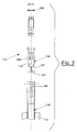
- Figure 2 shows a rapidly replaceable non-return device 110 for a petrochemical refinery reactor 112, according to the present invention, in which components identical and/or equivalent to those of the known art shown in Figure 1 are given the same reference numbers with the addition of 100.
- the non-return device 110 comprises a support tube 114, connected to a portion of a reactor 112, within which is provided a cylindrical cartridge 116 containing a ball 118.
- the cartridge 116 has lateral slots 120 for the outflow of the processed fluid, which also passes through corresponding apertures in the support tube 114 in which the cartridge 116 is inserted.
- the cartridge 116 also has in its lower part, around an inlet hole 121 for the processed fluid, a seat 122 for housing the ball 118.
- the support tube 114 is welded on to a portion of the reactor 112, in a vertical position.
- this support tube 114 can be fixed by mechanical means.
- the cartridge 116 is positioned in the support tube 114 in a removable way. This is done by providing the support tube 114 with a significant degree of deformability and elasticity in the area housing the cartridge 116, or by providing particular geometrical shapes for a coupling, of the conical type for example, between the cartridge 116 and the support tube 114, to facilitate the extraction of the cartridge.
- the extraction can be facilitated by using suitable materials, heat treatments, machining by stock removal, or plastic treatment.
- Figure 2 shows how at least one longitudinal aperture 124 is formed in the support tube 114, in the area housing the cartridge 116.
- These longitudinal apertures 124 can be, for example, milled cuts made along the axis of the support tube 114. More precisely, these milled cuts are created from an upper edge of this support tube 114.
- a taper washer 126 is also provided for fixing the cartridge 116 to the support tube 114.
- the ball 118 is pushed by the pressure of the flow of the process fluid which enters through the inlet hole 121, and is displaced axially until it uncovers the slots 120 through which the fluid flows out.
- Any back pressure pushes the ball 118 towards the seat 122, which is suitably shaped, enabling these components to form a seal and thus preventing the backward flow of the processed fluid.
- the cartridge 116 is replaced in order to bring the device 110 back into good working order.
- the replacement of the cartridge 116 is made rapid and easy by the apertures 124 formed in the tube 124, which give the tube 124 an elasticity such that its upper part can be widened during the removal of the cartridge 116.
- the taper washer 126 fixes the new device 110 and ensures proper adhesion between the support tube 114 and the new cartridge 116.
- the non-return device according to the present invention does not have to be replaced as a whole, in case of damage to the cartridge, except, obviously, in case of damage which may occasionally occur to the support tube.
- the replacement time for the non-return device is therefore reduced.
- non-return devices ensures that reactors will always operate with non-return devices in optimal conditions, because of the rapidity of replacement.
Landscapes
- Engineering & Computer Science (AREA)
- Chemical & Material Sciences (AREA)
- General Engineering & Computer Science (AREA)
- Mechanical Engineering (AREA)
- Combustion & Propulsion (AREA)
- Organic Chemistry (AREA)
- Chemical Kinetics & Catalysis (AREA)
- Devices And Processes Conducted In The Presence Of Fluids And Solid Particles (AREA)
- Production Of Liquid Hydrocarbon Mixture For Refining Petroleum (AREA)
- Check Valves (AREA)
- Vaporization, Distillation, Condensation, Sublimation, And Cold Traps (AREA)
- Quick-Acting Or Multi-Walled Pipe Joints (AREA)
Description
- The present invention relates to a rapidly replaceable non-return device for a petrochemical refinery reactor. Cylindrical devices acting as non-return valves are used in petroleum refinery reactors in some petrochemical processes. These devices allow the product subjected to the refining process to flow in one direction, while preventing the backward flow of the product and of any particles of catalyst which would damage the equipment located upstream of the said devices.
- In the current technical language these cylindrical devices are called "risers".
- Their operation is simple: each device has a terminal part housing a ball which is pushed by the pressure of the flow of the process fluid and is thus displaced axially until it uncovers radial slots through which the fluid can flow out.
- Any back pressure pushes the ball towards a suitable shaped housing, allowing it to form a seal and thus prevent a flow in the backward direction.
- Clearly, the axial and radial movements of the ball cause deformation, erosion and damage to its housing which result in the wear and sometimes the fracture of the said device, thus obliging the operator to replace it.
- At the present time, these devices are either welded or fixed mechanically inside reactors, in a vertical position. The welding itself, as well as the formation of process residues, causes problems for the removal of the device, making the work slow and particularly difficult to carry out.
- In the prior art, each non-return device is made in two or more parts, namely a support tube welded to the reactor and having within it a cylindrical cartridge which contains the ball and the sealing surface of the housing.
- In fact, as described above, solid residues of the process fluid infiltrate between the contact surfaces of the cartridge and the support tube, thus practically bonding the two parts and making them very difficult to disassemble: the operator is frequently obliged to replace the whole device, with an increase in time and cost.
- The object of the present invention is therefore to overcome the drawbacks mentioned above, in particular by providing a rapidly replaceable non-return device for a petrochemical refinery reactor which enables the plant downtime to be limited.
- Another object of the present invention is to provide a rapidly replaceable non-return device for a petrochemical refinery reactor which makes it possible to have assured replacement times, so that plant downtime can be correctly scheduled.
- A further object of the present invention is to provide a rapidly replaceable non-return device for a petrochemical refinery reactor which is particularly reliable, simple, functional and relatively inexpensive.
- These and other objects of the present invention are achieved by providing a rapidly replaceable non-return device for a petrochemical refinery reactor as described in Claim 1.
- Further characteristics of a rapidly replaceable non-return device for a petrochemical refinery reactor are specified in the subsequent claims.
- The characteristics and advantages of a rapidly replaceable non-return device for a petrochemical refinery reactor according to the present invention will be made clearer by the following description, provided by way of example and without restrictive intent, with reference to the attached schematic drawings in which:
-
Figure 1 is a sectional view in lateral elevation of a non-return device for a petrochemical refinery reactor according to the known art; and -
Figure 2 shows a sectional exploded view of a rapidly replaceable non-return device for a petrochemical refinery reactor according to the present invention. - With reference to
Figure 1 , this shows a non-return device, indicated as a whole by 10, for apetrochemical refinery reactor 12 according to the known art. - The
non-return device 10 comprises asupport tube 14, connected to a portion of thereactor 12, within which is fitted acylindrical cartridge 16 which contains aball 18. - The
cartridge 16 has lateral slots 20 for the outflow of the processed fluid, which also passes through corresponding apertures in thesupport tube 14 in which thecartridge 16 is inserted. - The
cartridge 16 also has in its lower part, around aninlet hole 21 for the processed fluid, aseat 22 for housing theball 18. - In the example in
Figure 1 , it can be seen that thesupport tube 14 is welded on to a portion of thereactor 12 in a vertical position. Alternatively, thissupport tube 14 can be fixed by mechanical means. -
Figure 2 shows a rapidly replaceablenon-return device 110 for apetrochemical refinery reactor 112, according to the present invention, in which components identical and/or equivalent to those of the known art shown inFigure 1 are given the same reference numbers with the addition of 100. - The
non-return device 110 comprises asupport tube 114, connected to a portion of areactor 112, within which is provided acylindrical cartridge 116 containing aball 118. - The
cartridge 116 haslateral slots 120 for the outflow of the processed fluid, which also passes through corresponding apertures in thesupport tube 114 in which thecartridge 116 is inserted. - The
cartridge 116 also has in its lower part, around aninlet hole 121 for the processed fluid, aseat 122 for housing theball 118. - In the example of
Figure 2 it can be seen that thesupport tube 114 is welded on to a portion of thereactor 112, in a vertical position. Alternatively, thissupport tube 114 can be fixed by mechanical means. Thecartridge 116 is positioned in thesupport tube 114 in a removable way. This is done by providing thesupport tube 114 with a significant degree of deformability and elasticity in the area housing thecartridge 116, or by providing particular geometrical shapes for a coupling, of the conical type for example, between thecartridge 116 and thesupport tube 114, to facilitate the extraction of the cartridge. - The extraction can be facilitated by using suitable materials, heat treatments, machining by stock removal, or plastic treatment.
- By way of example and without restrictive intent,
-
Figure 2 shows how at least onelongitudinal aperture 124 is formed in thesupport tube 114, in the area housing thecartridge 116. Theselongitudinal apertures 124 can be, for example, milled cuts made along the axis of thesupport tube 114. More precisely, these milled cuts are created from an upper edge of thissupport tube 114. - A
taper washer 126 is also provided for fixing thecartridge 116 to thesupport tube 114. - The operation of the rapidly replaceable
non-return device 110 for a petrochemical refinery reactor according to the invention is clearly indicated by the above description provided with reference to the figures, and is briefly as follows. - The
ball 118 is pushed by the pressure of the flow of the process fluid which enters through theinlet hole 121, and is displaced axially until it uncovers theslots 120 through which the fluid flows out. - Any back pressure pushes the
ball 118 towards theseat 122, which is suitably shaped, enabling these components to form a seal and thus preventing the backward flow of the processed fluid. - If the
non-return device 110, and particularly theseat 122, becomes damaged, thecartridge 116 is replaced in order to bring thedevice 110 back into good working order. - The replacement of the
cartridge 116 is made rapid and easy by theapertures 124 formed in thetube 124, which give thetube 124 an elasticity such that its upper part can be widened during the removal of thecartridge 116. - When the damaged
cartridge 116 has been removed and replaced with anew cartridge 116, thetaper washer 126 fixes thenew device 110 and ensures proper adhesion between thesupport tube 114 and thenew cartridge 116. The characteristics of the rapidly replaceable non-return device for a petrochemical refinery reactor according to the present invention, and the advantages thereof, are clear from the above description. - The following remarks and comments will be made in conclusion, in order to define the aforesaid advantages more precisely and clearly.
- In the first place, it should be noted that the non-return device according to the present invention does not have to be replaced as a whole, in case of damage to the cartridge, except, obviously, in case of damage which may occasionally occur to the support tube.
- The replacement time for the non-return device is therefore reduced.
- The advantage of having assured replacement times, and consequently the possibility of correctly scheduling plant downtimes, should also be emphasized.
- Additionally, the use of non-return devices according to the invention ensures that reactors will always operate with non-return devices in optimal conditions, because of the rapidity of replacement.
- Finally, it is pointed out the simplicity and reliability of use of the non-return devices according to the invention, and the low production costs, with respect to the known art.
- The scope of protection of the invention is thus delimited by the attached claims.
Claims (12)
- Rapidly replaceable non-return device (110) for a petrochemical refinery reactor (112), of the type comprising a support tube (114), connected to a portion of the said reactor (112), the said support tube (114) being provided internally with a cartridge (116) containing a ball (118), the cartridge (116) having, around an inlet hole (121) for a processed fluid, a seat (122) for housing the said ball (118), and having slots (120) for the outflow of the said processed fluid, characterized in that the said cartridge (116) is fitted removably in the said support tube (114).
- Non-return device (110) according to Claim 1, characterized in that at least one longitudinal aperture (124) is formed in the said support tube (114).
- Non-return device (110) according to Claim 2, characterized in that the said at least one longitudinal aperture (124) is a milled cut formed along the axis of the said support tube (114).
- Non-return device (110) according to Claim 3, characterized in that the said milled cut is created from an upper edge of the said support tube (114).
- Non-return device (110) according to Claim 2, characterized in that a taper washer (126) is provided for fixing the said cartridge (116) to the said support tube (114).
- Non-return device (110) according to Claim 1, characterized in that the said cartridge (116) is cylindrical.
- Non-return device (110) according to Claim 1, characterized in that the said slots (120) are formed laterally in the said cartridge (116) and in that apertures in the said support tube (114) correspond to the said slots (120).
- Non-return device (110) according to Claim 1, characterized in that the said seat (122) is provided in the lower part of the said cartridge (116).
- Non-return device (110) according to Claim 1, characterized in that the said support tube (114) is welded on to a portion of the said reactor (112), in a vertical position.
- Non-return device (110) according to Claim 1, characterized in that the said support tube (114) is fixed mechanically to a portion of the said reactor (112).
- Non-return device (110) according to Claim 2, characterized in that the said at least one longitudinal aperture (124) is formed in an area in which the said cartridge (116) is housed.
- Non-return device (110) according to Claim 1, characterized in that the said seat (122) is suitably shaped to form a seal in conjunction with the said ball (118).
Applications Claiming Priority (3)
| Application Number | Priority Date | Filing Date | Title |
|---|---|---|---|
| ITMI20022092 | 2002-10-03 | ||
| ITMI20022092 ITMI20022092A1 (en) | 2002-10-03 | 2002-10-03 | RAPID REPLACEMENT NON-RETURN DEVICE, |
| PCT/EP2003/011062 WO2004030804A1 (en) | 2002-10-03 | 2003-10-01 | Non-return valve for a petrochemical reactor |
Publications (2)
| Publication Number | Publication Date |
|---|---|
| EP1556161A1 EP1556161A1 (en) | 2005-07-27 |
| EP1556161B1 true EP1556161B1 (en) | 2008-06-18 |
Family
ID=32051226
Family Applications (1)
| Application Number | Title | Priority Date | Filing Date |
|---|---|---|---|
| EP03757917A Expired - Lifetime EP1556161B1 (en) | 2002-10-03 | 2003-10-01 | Non-return valve for a petrochemical reactor |
Country Status (12)
| Country | Link |
|---|---|
| US (1) | US7264015B2 (en) |
| EP (1) | EP1556161B1 (en) |
| JP (1) | JP4537852B2 (en) |
| KR (1) | KR100990026B1 (en) |
| CN (1) | CN100354037C (en) |
| AU (1) | AU2003273952A1 (en) |
| CA (1) | CA2468229C (en) |
| DE (1) | DE60321699D1 (en) |
| ES (1) | ES2306889T3 (en) |
| IT (1) | ITMI20022092A1 (en) |
| RU (1) | RU2329096C2 (en) |
| WO (1) | WO2004030804A1 (en) |
Families Citing this family (8)
| Publication number | Priority date | Publication date | Assignee | Title |
|---|---|---|---|---|
| JP2006200552A (en) * | 2005-01-18 | 2006-08-03 | Fuji Koki Corp | Check valve |
| KR100756651B1 (en) * | 2005-07-29 | 2007-09-07 | 신일환 | Overflow shutoff valve for liquefied petroleum gas container |
| US9394930B2 (en) | 2010-11-15 | 2016-07-19 | K.J. Manufacturing Co. | Method and device for coolant recycling |
| WO2012068102A2 (en) | 2010-11-15 | 2012-05-24 | K.J. Manufacturing Co. | Method and device for coolant recycling |
| RU2449192C1 (en) * | 2010-11-29 | 2012-04-27 | Общество с ограниченной ответственностью "Русская электротехническая компания" ("РУСЭЛКОМ") | Reversible check valve |
| CA2908502C (en) * | 2013-03-15 | 2021-02-16 | K.J. Manufacturing Co. | Method and device for coolant recycling |
| FI128456B (en) * | 2018-11-21 | 2020-05-29 | Neste Oyj | A tubular riser for a reactor of a hydrocarbon processing plant and a method for maintenance of the reactor |
| CN112569874B (en) * | 2020-11-20 | 2022-05-20 | 上海竣铭化工工程设计有限公司 | Gas-liquid distributor for fluidized bed reactor and assembling method thereof |
Family Cites Families (15)
| Publication number | Priority date | Publication date | Assignee | Title |
|---|---|---|---|---|
| US136412A (en) * | 1873-03-04 | Improvement in adjustable valves for bored or driven wells | ||
| US139018A (en) * | 1873-05-20 | Improvement | ||
| US2192541A (en) * | 1939-03-03 | 1940-03-05 | Homer N Davis | Union ball check valve |
| US3026903A (en) * | 1959-04-27 | 1962-03-27 | Harold Brown Company | Magnetic check valve |
| JPS5457533U (en) * | 1977-09-29 | 1979-04-20 | ||
| US4816137A (en) * | 1983-05-27 | 1989-03-28 | Total Engineering And Research Company | Method for cracking residual oils |
| US4568337A (en) * | 1984-04-17 | 1986-02-04 | Richards Medical Company | Ventilation tube permitting two-way gaseous communication with one-way liquid valve |
| JPS60172064U (en) * | 1984-04-20 | 1985-11-14 | 日立粉末冶金株式会社 | Check valve installation structure |
| US4874583A (en) * | 1987-11-27 | 1989-10-17 | Texaco Inc. | Bubble cap assembly in an ebullated bed reactor |
| DE8915063U1 (en) * | 1989-12-22 | 1991-04-25 | Behr-Thomson Dehnstoffregler GmbH & Co, 7014 Kornwestheim | Thermostat valve |
| SU1762968A1 (en) * | 1990-02-05 | 1992-09-23 | Кишиневская Мебельная Фабрика N2 Им.М.В.Фрунзе | Cartridge filter |
| JP2000065227A (en) * | 1998-08-24 | 2000-03-03 | Mitsubishi Electric Corp | Check valve |
| DE19915889A1 (en) * | 1999-04-08 | 2000-10-19 | Zimmermann & Jansen Gmbh | Fluid catalytic cracking system and flap valve for such |
| RU2184293C2 (en) * | 2000-07-10 | 2002-06-27 | Федеральное государственное унитарное предприятие "Сибирский химический комбинат" | Ball valve |
| JP4317652B2 (en) * | 2000-07-28 | 2009-08-19 | 三菱重工業株式会社 | Substructure of fuel assembly for nuclear reactor and thimble screw for fuel assembly |
-
2002
- 2002-10-03 IT ITMI20022092 patent/ITMI20022092A1/en unknown
-
2003
- 2003-10-01 ES ES03757917T patent/ES2306889T3/en not_active Expired - Lifetime
- 2003-10-01 KR KR1020047008524A patent/KR100990026B1/en not_active Expired - Fee Related
- 2003-10-01 JP JP2004540792A patent/JP4537852B2/en not_active Expired - Fee Related
- 2003-10-01 EP EP03757917A patent/EP1556161B1/en not_active Expired - Lifetime
- 2003-10-01 WO PCT/EP2003/011062 patent/WO2004030804A1/en not_active Ceased
- 2003-10-01 CN CNB2003801000193A patent/CN100354037C/en not_active Expired - Fee Related
- 2003-10-01 AU AU2003273952A patent/AU2003273952A1/en not_active Abandoned
- 2003-10-01 CA CA 2468229 patent/CA2468229C/en not_active Expired - Fee Related
- 2003-10-01 RU RU2004116818A patent/RU2329096C2/en active
- 2003-10-01 DE DE60321699T patent/DE60321699D1/en not_active Expired - Lifetime
- 2003-10-01 US US10/497,314 patent/US7264015B2/en not_active Expired - Lifetime
Also Published As
| Publication number | Publication date |
|---|---|
| EP1556161A1 (en) | 2005-07-27 |
| KR100990026B1 (en) | 2010-10-26 |
| RU2004116818A (en) | 2005-03-27 |
| ES2306889T3 (en) | 2008-11-16 |
| US7264015B2 (en) | 2007-09-04 |
| ITMI20022092A1 (en) | 2004-04-04 |
| CN100354037C (en) | 2007-12-12 |
| DE60321699D1 (en) | 2008-07-31 |
| WO2004030804A1 (en) | 2004-04-15 |
| CA2468229A1 (en) | 2004-04-15 |
| KR20050069926A (en) | 2005-07-05 |
| US20050103384A1 (en) | 2005-05-19 |
| CN1684759A (en) | 2005-10-19 |
| JP4537852B2 (en) | 2010-09-08 |
| CA2468229C (en) | 2011-12-20 |
| AU2003273952A1 (en) | 2004-04-23 |
| WO2004030804A8 (en) | 2004-05-27 |
| RU2329096C2 (en) | 2008-07-20 |
| JP2006501418A (en) | 2006-01-12 |
Similar Documents
| Publication | Publication Date | Title |
|---|---|---|
| CA2468229C (en) | Non-return valve for a petrochemical reactor | |
| US5320289A (en) | Abrasive-waterjet nozzle for intelligent control | |
| KR20200041334A (en) | Spin-on fluid processing apparatus and method | |
| JP2005505415A (en) | Drawer base plate with laser or water jet cutting aperture | |
| WO2017075566A1 (en) | Double nozzle for a laser processing head | |
| EP3464800A1 (en) | Improved check valve | |
| JP2004537640A (en) | Tools for breaking up coke | |
| EP1861218B1 (en) | Collet and lock nut | |
| CA3212412A1 (en) | Fixing system of a wear element in a support element of an earth moving machine through a pin, and a retainer | |
| JP6262807B2 (en) | Filter for high-pressure nozzle, high-pressure nozzle, and method for manufacturing filter for high-pressure nozzle | |
| EP0146252B1 (en) | Leak-proof, high pressure, high velocity, fluid jet cutting nozzle assembly | |
| US4611672A (en) | Drill bit | |
| SE505360C2 (en) | Centrifuge drum outlet nozzle | |
| JP2009233796A (en) | Workpiece detection device, workpiece detection method, and machine tool equipped with workpiece detection device | |
| CN216097865U (en) | Built-in cutting fluid cooling integrated device | |
| JP7610814B2 (en) | Coolant Injection Device | |
| KR20120011923A (en) | Hydroforming Punch | |
| JP7188862B2 (en) | Welding electrode polishing method and polishing apparatus | |
| JP4408362B2 (en) | Multi-punch grinding jig, punch die and grinding method | |
| KR102482544B1 (en) | High-strength projection welding machine with a guide pin that facilitates fume discharge fume | |
| JP7302857B2 (en) | bit and punch | |
| KR200273647Y1 (en) | a punch for cutting of coil spring | |
| CN214578866U (en) | Needle valve | |
| JP2959904B2 (en) | Fluid controller | |
| CN110842077A (en) | Manufacturing method of valve element water outlet hole, valve element and water faucet |
Legal Events
| Date | Code | Title | Description |
|---|---|---|---|
| PUAI | Public reference made under article 153(3) epc to a published international application that has entered the european phase |
Free format text: ORIGINAL CODE: 0009012 |
|
| 17P | Request for examination filed |
Effective date: 20050503 |
|
| AK | Designated contracting states |
Kind code of ref document: A1 Designated state(s): AT BE BG CH CY CZ DE DK EE ES FI FR GB GR HU IE IT LI LU MC NL PT RO SE SI SK TR |
|
| AX | Request for extension of the european patent |
Extension state: AL LT LV MK |
|
| DAX | Request for extension of the european patent (deleted) | ||
| RBV | Designated contracting states (corrected) |
Designated state(s): DE ES FR RO |
|
| GRAP | Despatch of communication of intention to grant a patent |
Free format text: ORIGINAL CODE: EPIDOSNIGR1 |
|
| GRAS | Grant fee paid |
Free format text: ORIGINAL CODE: EPIDOSNIGR3 |
|
| GRAA | (expected) grant |
Free format text: ORIGINAL CODE: 0009210 |
|
| AK | Designated contracting states |
Kind code of ref document: B1 Designated state(s): DE ES FR RO |
|
| REF | Corresponds to: |
Ref document number: 60321699 Country of ref document: DE Date of ref document: 20080731 Kind code of ref document: P |
|
| REG | Reference to a national code |
Ref country code: RO Ref legal event code: EPE |
|
| REG | Reference to a national code |
Ref country code: ES Ref legal event code: FG2A Ref document number: 2306889 Country of ref document: ES Kind code of ref document: T3 |
|
| PLBE | No opposition filed within time limit |
Free format text: ORIGINAL CODE: 0009261 |
|
| STAA | Information on the status of an ep patent application or granted ep patent |
Free format text: STATUS: NO OPPOSITION FILED WITHIN TIME LIMIT |
|
| 26N | No opposition filed |
Effective date: 20090319 |
|
| REG | Reference to a national code |
Ref country code: FR Ref legal event code: PLFP Year of fee payment: 13 |
|
| REG | Reference to a national code |
Ref country code: FR Ref legal event code: PLFP Year of fee payment: 14 |
|
| REG | Reference to a national code |
Ref country code: FR Ref legal event code: PLFP Year of fee payment: 15 |
|
| REG | Reference to a national code |
Ref country code: FR Ref legal event code: PLFP Year of fee payment: 16 |
|
| PGFP | Annual fee paid to national office [announced via postgrant information from national office to epo] |
Ref country code: FR Payment date: 20200917 Year of fee payment: 18 |
|
| PGFP | Annual fee paid to national office [announced via postgrant information from national office to epo] |
Ref country code: ES Payment date: 20201102 Year of fee payment: 18 Ref country code: DE Payment date: 20200917 Year of fee payment: 18 Ref country code: RO Payment date: 20201001 Year of fee payment: 18 |
|
| REG | Reference to a national code |
Ref country code: DE Ref legal event code: R119 Ref document number: 60321699 Country of ref document: DE |
|
| PG25 | Lapsed in a contracting state [announced via postgrant information from national office to epo] |
Ref country code: RO Free format text: LAPSE BECAUSE OF NON-PAYMENT OF DUE FEES Effective date: 20211001 Ref country code: DE Free format text: LAPSE BECAUSE OF NON-PAYMENT OF DUE FEES Effective date: 20220503 |
|
| PG25 | Lapsed in a contracting state [announced via postgrant information from national office to epo] |
Ref country code: FR Free format text: LAPSE BECAUSE OF NON-PAYMENT OF DUE FEES Effective date: 20211031 |
|
| REG | Reference to a national code |
Ref country code: ES Ref legal event code: FD2A Effective date: 20221125 |
|
| PG25 | Lapsed in a contracting state [announced via postgrant information from national office to epo] |
Ref country code: ES Free format text: LAPSE BECAUSE OF NON-PAYMENT OF DUE FEES Effective date: 20211002 |