EP1555395A1 - Dispositif de commande de gaz pour banc d'essai - Google Patents
Dispositif de commande de gaz pour banc d'essai Download PDFInfo
- Publication number
- EP1555395A1 EP1555395A1 EP04293145A EP04293145A EP1555395A1 EP 1555395 A1 EP1555395 A1 EP 1555395A1 EP 04293145 A EP04293145 A EP 04293145A EP 04293145 A EP04293145 A EP 04293145A EP 1555395 A1 EP1555395 A1 EP 1555395A1
- Authority
- EP
- European Patent Office
- Prior art keywords
- control
- signal
- angular position
- interface
- tra
- Prior art date
- Legal status (The legal status is an assumption and is not a legal conclusion. Google has not performed a legal analysis and makes no representation as to the accuracy of the status listed.)
- Granted
Links
Images







Classifications
-
- F—MECHANICAL ENGINEERING; LIGHTING; HEATING; WEAPONS; BLASTING
- F01—MACHINES OR ENGINES IN GENERAL; ENGINE PLANTS IN GENERAL; STEAM ENGINES
- F01D—NON-POSITIVE DISPLACEMENT MACHINES OR ENGINES, e.g. STEAM TURBINES
- F01D21/00—Shutting-down of machines or engines, e.g. in emergency; Regulating, controlling, or safety means not otherwise provided for
- F01D21/003—Arrangements for testing or measuring
Definitions
- the invention relates generally to turbomachines. It applies in particular to aircraft engines.
- the present invention improves the situation.
- the invention proposes a gas control device for an aircraft turbomachine, type comprising a command set, able to act on the native command of the turbomachine, according to a manual input defined by a control member, in which the control member is arranged to deliver an angular position signal of handle, in the form of a voltage, in particular a DC voltage.
- the device further comprises a actuator module adapted to receive as input the transformed angular position signal and to output a native command for control turbomachines hydromechanical system, the automaton being adapted to control the actuator module comprising a motor and gearbox.
- the actuator module is able to act electromechanically on a lever of a turbomachine regulator with hydromechanical control and, in addition, the controller is adapted to control the lever of the actuator module.
- the interface is capable, from an excitation signal transmitted by a regulator turbomachine to convert an angular position signal transformed into two signals sinusoidal signals transmitted to the turbomachine regulator whose native control is sinusoidal type signals.
- the transformed angular position signal comprises either a signal linear, or two trigonometric signals.
- FIG. 1 is a schematic diagram of a test bench able to work on different types of engines, illustrated.
- Figure 2 is the same schematic diagram, a little more detailed, but without showing the engines.
- control member may comprise a physical controller PM, to ensure proper gas control.
- this lever PM acts on the lever CL via a position control 2, said "Servo controller”.
- CL lever is associated with a potentiometric type angular position sensor CL1.
- This angular position, or its copy, is transmitted electrically in the form of a signal position analog CLS1, in particular a continuous potentiometric voltage signal, to a command set 4, to which we will return.
- Reference MT1 designates a motor with gas control by hydromechanical regulation. It can be one of the following engines: CFM56-2, CFM56-3, JT8D9 to JT8D17, M53, ATAR, LARZAC, all manufactured by the Applicant.
- the input of the command on the engine side is then a lever 89.
- the control unit 4 comprises an electronic spool 41 (TEG), which acts on an actuator 81, which controls in turn the lever 89.
- electronic drawer means a module that can be in the form of a drawer receiving electronic racks and able to act on means of the actuator type, regulator or others.
- Reference MT2 designates a motor with electrical voltage control, as for example the model M88 of the Applicant.
- the command set 4 includes a specific drawer of this motor 42 (TSM88), which is responsible for providing the adequate voltages.
- Reference MT3 denotes a throttle-controlled throttle-type motor, especially for a regulator called “FADEC” ("Full Authority Digital Engine” Control "), such as the CFM56-5A / 5B / 5C engines, such engines may operate in either ECU (Engine Control Unit) or EEC (Electronic Engine) mode Control ”)
- FADEC Full Authority Digital Engine
- the FADEC controller basically involves a redundant calculator.
- Reference MT3 also covers engines whose control computer is not redundant, like so-called PMC ("Power Management Control") computers, for example the CF6 80 C2 PMC / PMUX engine.
- PMC Power Management Control
- control unit 4 comprises a stage 43, which can operate by simply copying signals CLS2 from the lever CL, in the measure where it is also output synchro-resolver type.
- Reference MT4 designates a throttle-controlled motor by means of synchro-resolving signals, as for example the engine CF6 80 E1 FADEC, CF680 C2 FADEC or CFM 56-7B of the Applicant.
- control unit 4 comprises a specific interface 44 (ISCF6), which can operate by adaptation of the signals coming from the lever CL, insofar as this one is a synchro-resolver type output.
- ISCF6 specific interface 44
- elements 1 and 4 are placed in the control room. If it's happened, the actuator 89 is placed on the reactor or in the immediate vicinity.
- actuators are possible depending on the types of reactor (in particular: travel, engine torque and idle torque)
- FIG. 7 illustrates more particularly the box of the resolver interface intended for work with a redundant signal regulator.
- this case includes two resolver interfaces 70-1 and 70-2 each receiving as input the angle command signal of the automaton.
- the latter includes two analog outputs each connected to an interface different resolver.
- the resolver interface receiving two trigonometric type signals can be a card electronics comprising conventional components providing the multiplication functions analog signals.
- This man-machine interface also makes it possible to modify the angular position of the by sending appropriate commands to the controller. For this, the operator can click on virtual buttons M ++, M +, M- and M - - presented on the screen to increase or to decrease the angular position of the joystick from a value displayed on the screen. It can also directly enter the value of the desired angular position.
- the button virtual M ++ has a step of increment (or slope) more important than the step of incrementation virtual button M +. The same goes for the buttons M- and M - -.
- Figure 9 shows other virtual buttons attributed to the action of bringing the joystick on the stop Idle Vol (virtual button RV), the action of bringing the lever on the stop Idle Sol (RS virtual button), indicating that the operator skips the stop (virtual button B).
- the position of the indicators I that can move on graded scales indicate the values of the 4 stops.
- the operator can click on virtual M ++ buttons, M +, M- and M - - displayed on the screen to increase or decrease the current setpoint C. Soil and flight idle values can also be modified from the same maneuvers by the operator.
- these values are transmitted to the PLC 4 by a PC-type computer called federator and used as a gateway between the PLC and the pilot screen.
- the automaton 4 transmits these values to the physical controller 1.
- the parameters of the steering member include the deflection of the steering member, the position of the stops of the handle, the value of the desired angular position, the acceleration per angular unit and the deceleration per angular unit associated with angular by the operator, either to the virtual buttons M ++, M +, M-, M- - (which corresponds to the step increment), or at the position of each stop.
- the selection of the motor control law by the operator amounts to selecting the type of engine (or turbomachine) wanted.
- the selected engine can send an electronic drawer the expected type of signal, the drawer 41 can then act on the actuator 81.
- FIGS. 11 to 22 illustrate an example of implementation of the automaton in the form of logic circuits.
- the human-machine interface of the HMI type for example a graphical interface connected to the PLC, allows an operator to enter data for perform tests on a selected engine on the test bench. This graphical interface also allows the operator to follow the progress of the current test.
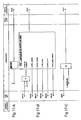
- Figure 10 illustrates the meaning of the symbols used in the logic circuits of Figures 11 to 22.
- the symbol 100 associates two inputs into an output signal.
- the symbol 108 illustrates a setting the value of the input signal to 1.
- Symbol 110 illustrates a setting to 0 of the input signal.
- Symbols 112 and 114 illustrate logical flip-flops.
- the symbols 114 and 116 illustrate a trigger on a rising edge and a falling edge of a signal.
- Symbol 120 illustrates a timing of a signal.
- Symbol 124 illustrates equality between the input and output signal.
- the symbol 126 checks the superiority between a signal and a value and delivers the main signal as the output signal.
- the symbol 128 checks the superiority or equality between a main signal and a value and delivers the main signal as an output signal.
- the symbol 130 checks the inferiority between a main signal and a value and outputs the main signal as the output signal.
- the symbol 132 checks for inferiority or equality between a main signal and a value and delivers the main signal as the output signal.
- the symbol 134 checks the difference between a signal and a value and delivers the main signal as the output signal.
- the symbol 136 adds two input signals and outputs a corresponding output signal.
- the symbol 138 multiplies two input signals and outputs a corresponding output signal.
- Symbol 142 divides two input signals and outputs a corresponding output signal. Acronyms are also used to designate logic circuits like the initials MOVE which designates an instruction to copy a memory into another memory.
- an operator who wishes to carry out a test must choose a motor among the proposed engines, enter and validate the minimum and maximum angles of the joystick, and start the test.
- FIGS. 13-A and 13-B respectively illustrate circuitry for detecting voltage faults at cards 1 and 2 of the PLC.
- the E0.0 or E0.1 input of the PLC is activated as soon as a voltage fault is detected at the level of the card 1, respectively 2.
- These logic circuits provide a signal on outputs M153.0 and M153.1 of the PLC warning of current faults.
- other logic circuits allow the detection of specific faults of the PLC.
- Figure 11-A shows a fault acknowledgment by an operator entering the MW104 command.
- the fault acknowledgment information is presented by the interface (MW104 and MW152) and the M4.0 output of the controller resets the test and allows its recovery.
- MOVE enclosures are instructions for copying a memory into another memory, here a copy of the information for an on-screen display.
- Figure 11-B illustrates the acquisition of the minimum angle of the joystick.
- An operator captures a value of the minimum angle of the joystick to be applied between 0 ° and 360 ° (command MW108). This value must be different from 0 and is associated with an average value MW150 which must be different from 256 to validate the value of the minimum angle of the joystick.
- the voltage signal on the M4.1 output of the PLC represents the validation of the acquisition the minimum angle of the joystick.
- Figure 11-C illustrates the acquisition of the maximum angle of the joystick.
- An operator captures a value of the maximum angle of the joystick to be applied between 0 ° and 360 ° (command MW106). This value must be different from 0 and is associated with the average value MW150 which must be different from 256 to validate the value of the maximum angle of the joystick.
- the voltage signal on the output of the PLC M4.2 represents the validation of the acquisition the maximum angle of the joystick.
- Figures 12-A and 12-B illustrate the logic circuits for displaying on the interface graph of MW106 value of maximum joystick angle and MW108 value the minimum angle of the joystick once validated as shown in Figures 11-B and 11-C.
- the 0 values at the input of the MOVE boxes are used for initialization.
- the angular movement of the joystick corresponds to a "law lever". This travel is selected as described above by the user.
- Figures 14-A to 14-E each illustrate a logic circuit used for one of the five motors that can choose the operator by the command MW100.
- the choice of the motor can only be made when the state of the test is at a standstill: the value on / off control MW 102 is at 0 when the state is stopped, value can be changed by entering the operator.
- the command MW100 can be equal to an integer of 1 to 5 to designate the motor chosen by the operator, the motors being numbered from 1 to 5 in the examples of FIGS.
- the operator can enter the values of the minimum and maximum of the angular range of the chosen motor, the angular range varying from -360 ° to 360 °.
- These controls are MD170 and MD174 for Engine 1, MD180 and MD184 for Engine 2, MD190 and MD194 for motor 3, MD200 and MD204 for motor 4, MD210 and MD214 for the motor 5.
- the angular range related to the choice of the motor is called “law of motor control "or" motor law ".
- the on / off command MW102 has been set to 1.
- the logic circuit for which MW100 1 is activated.
- the controller gathers the MD158 and MD162 voltage values associated with the values minimum and maximum angle of the selected motor.
- the voltage values MD158 and MD162 corresponding to the minimum angle values and selected motor are used as inputs by the PLC in FIGS. 15-A and 15-B. These voltage values are copied into memory by the MOVE box, which allows to obtain the voltage values corresponding to the fictitious values of the minimum angles and maximum MD110 and MD114 of the joystick for the chosen motor. So the angular range of the joystick is modified according to the selected motor and the associated control law.
- the logic circuit of the automaton of FIG. 16 converts the voltage value of the potentiometer of the PEW controller 304 to a voltage value MD154 corresponding to the angle of the controller in progress. This conversion is done from the voltage range of the potentiometer, voltage values corresponding to the values of the maximum actual angles and minimum of the joystick, voltage values corresponding to the dummy values of the Minimum and maximum MD110 and MD114 angles of the joystick for the selected motor.
- FIGS. 17-A to 17-C illustrate the logic circuits leading to the calculation of the setpoint angle in degrees then in radian.
- Figure 17-A corresponds to an initialization circuit before calculating the new setpoint angle.
- the output MD20 is a voltage representing a value in degrees.
- the logic circuit of FIG. 17-B makes it possible to obtain at the output the value of the angle of the joystick in degrees MD20.
- Figure 17-C illustrates the conversion of the MD20 value to a MD24 radian angle by the multiplication of a factor ⁇ / 180.
- the controller can propose, as indicated in the description above, to the interface resolver, a setpoint value which is then transformed into two values of sine and cosine. It is also possible to propose an automaton that delivers output values, cosine and sine of the setpoint angle.
- Figures 18 illustrate an automaton proposing at the output the values of cosine and sinus the setpoint angle of the joystick.
- the value of the MD24 radian angle of the controller setpoint is at the input of the logic circuit COS which transforms this value into an MD30 value of cosine of this angle at the output of the logic circuit.
- this value MD30 is at the input of the scaling logic circuit FC106, the values 1 and -1 at the input represent the high and low limits of the input signal.
- the M3.0 value is a bit of always valid to 1 which serves to validate the call of the logic circuit FC106.
- the value of scaled cosine MW36 is output from the PLC, output MW34 indicates the state of scaling of the cosine.
- the value of the MD24 radian angle of the setpoint of the joystick is in input of the logic circuit SIN which converts this value into an MD40 value of sine of this angle at the output of the logic circuit.
- this value MD40 is at the input of scaling logic, the input values 1 and -1 represent the high limits and bass of the input signal.
- the value M3.0 is a validation bit always at 1 which is used to validate the call of the logic circuit FC106.
- the value of the sinus scaled MW46 is in output of the PLC, output MW44 indicates the state of scaling of the sine.
- Figures 19 illustrate logic scaling circuits for the outputs of the values angle in degrees MD20 of the logic circuits of FIGS. 17-A and 17-B.
- the circuit logic of Figure 19-A receives, as high and low limits of the input signal, the values of voltage corresponding to the minimum and maximum angles MD158 and MD162 of the motor chosen (angular range of the motor law).
- the M3.1 input signal is always at zero.
- the logic circuit of Figure 19-A allows the copy of the instruction in the angular range of the motor law for the ACQ acquisition system called output MW56 and the simple recopy of the setpoint in the angular range of the motor law called MW54 output.
- the circuit logic of Figure 19-B receives, as high and low limits of the input signal, the values 140 ° and 40 ° by way of example only.
- the M3.1 input signal is always at zero. AT from these inputs, the logic circuit of Figure 19-B allows the copy of the instruction in the angular range of the motor law for the ACQ acquisition system called output MW60 and the simple recopy of the setpoint in the angular range of the motor law called MW58 output.
- Figures 20 allow assignment to analog outputs of the words automaton internal to the automaton.
- Figures 20-A, 20-B and 20-C are redundant respectively with FIGS. 20-E, 20-F, 20-G so that the outputs of the automaton are redundant for a resolver interface like that of Figure 7.
- the circuit of Figure 20-A proposes, from input MW46 representing the sine of the setpoint angle, an output PAW272 as the first sinus output from the setpoint angle to the resolver interface.
- the circuit of Figure 20-E is the redundancy of the circuit of Figure 20-A and proposes an output PAW288 as the second sinus output from the setpoint angle to the resolver interface.
- the circuit of the figure 20-B proposes, from input MW36 representing the cosine of the setpoint angle, a PAW274 output as the first cosine output from the setpoint angle at the interface solver.
- the circuit of Figure 20-F is the redundancy of the circuit of Figure 20-B and proposes a PAW290 output as the second output of the cosine of the setpoint angle at the resolver interface.
- the logic circuit of FIG. 20-C allows to output a copy of the motor control in the scale of the motor law for the ACQ acquisition system from corresponding input MW56 (in Figure 19-A) at the setpoint angle scaled in the motor law.
- the logic circuit of FIG. 20-G makes it possible to output a copy of the command motor in the [40 °, 140 °] scale for the ACQ acquisition system from the input MW60 (of Fig. 19-B) corresponding to the scaled setpoint.
- the logic circuit of FIG. 20-D makes it possible to deliver, to the housing 41 (servo-amplifier of power) of Figure 3, voltage signals PAW278 and PAW294.
- the PAW 278 signal corresponds to the voltage signal of the joystick potentiometer PEW 304
- the signal PAW 294 corresponds to half the PEW304 voltage of the joystick potentiometer.
Landscapes
- Engineering & Computer Science (AREA)
- Mechanical Engineering (AREA)
- General Engineering & Computer Science (AREA)
- Combined Controls Of Internal Combustion Engines (AREA)
- Testing Of Engines (AREA)
- Control Of Turbines (AREA)
- Mechanical Control Devices (AREA)
- Feedback Control In General (AREA)
- Electrical Control Of Air Or Fuel Supplied To Internal-Combustion Engine (AREA)
- Output Control And Ontrol Of Special Type Engine (AREA)
- Control Of Vehicle Engines Or Engines For Specific Uses (AREA)
- Sampling And Sample Adjustment (AREA)
Abstract
Description
- un automate, capable de convertir le signal de position angulaire de manette en un signal de position angulaire transformé, en fonction d'une loi de commande choisie, et
- au moins une interface, capable de convertir le signal de position angulaire transformé en deux signaux sinusoïdaux, en particulier de type résolveur,
- la figure 1 est un schéma de principe d'un banc d'essais apte à travailler sur différent types de moteurs, illustrés,
- la figure 2 est le schéma de principe de la figure 1, plus détaillé,
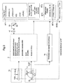
- la figure 3 illustre le schéma de principe d'un banc d'essai selon l'invention apte à travailler avec différents types de moteurs,
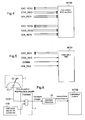
- la figure 4 illustre de façon schématique, les échanges de signaux entre un générateur de signaux sinusoïdaux du banc d'essai selon l'invention et un premier type de calculateur,
- la figure 5 illustre de façon schématique, les échanges de signaux entre un générateur de signaux sinusoïdaux du banc d'essai selon l'invention et un deuxième type de calculateur,
- la figure 6 illustre de façon schématique, le schéma de principe d'un banc d'essai selon l'invention apte à travailler avec un moteur fonctionnant à partir de signaux sinusoïdaux, et
- la figure 7 illustre de façon schématique, un générateur de signaux sinusoïdaux du banc d'essai selon l'invention apte à travailler avec le deuxième type de calculateur de la figure 4,
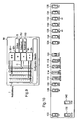
- la figure 8 illustre de façon schématique, le schéma de principe d'un banc d'essai selon l'invention comprenant une interface pour opérateur,
- la figure 9 illustre de façon schématique, une réalisation de l'interface pour opérateur selon l'invention,
- la figure 10 illustre la légende des boítiers utilisés dans les logigrammes des circuits logiques de l'automate des figures 11 à 20,
- les figures 11-A à 11-C illustrent sous forme de logigrammes les circuits logiques de l'automate permettant la récupération des demandes de l'opérateur,
- les figures 12-A et 12-B illustrent sous forme de logigrammes d'autres circuits logiques de l'automate permettant la récupération des demandes de l'opérateur,
- les figures 13-A et 13-B illustrent sous forme de logigrammes des circuits logiques de l'automate permettant la gestion des défauts,
- les figures 14-A à 14-E illustrent sous forme de logigrammes cinq circuits logiques de l'automate permettant la récupération de paramètres moteurs,
- les figures 15-A et 15-B illustrent sous forme de logigrammes des premiers circuits logiques de l'automate permettant la récupération d'angles manette minimum et maximum pour un moteur choisi,
- la figure 16 illustre sous forme de logigramme un deuxième circuit logique de l'automate permettant la récupération de l'angle manette à partir du signal d'un potentiomètre de manette,
- les figures 17-A à 17-C illustrent sous forme de logigrammes trois circuits logiques de l'automate permettant le calcul en sortie de l'angle manette en degré et/ou en radian,
- les figures 18-A à 18-D illustrent sous forme de logigrammes des circuits logiques de l'automate permettant le calcul et la mise à l'échelle des cosinus et des sinus à partir des sorties des figures 17,
- les figures 19-A et 19-B illustrent sous forme de logigrammes deux circuits logiques de l'automate permettant la recopie de la commande moteur dans l'échelle de la loi moteur et la recopie de la commande moteur dans l'échelle une échelle donnée pour un système d'acquisition ACQ,
- les figures 20-A à 20-G illustrent sous forme de logigrammes des circuits logiques de l'automate permettant la délivrance de sorties analogiques de l'automate, notamment pour un calculateur redondant.
- soit par actionneur: commande électromécanique du levier de commande de régulation réacteur,
- soit par signaux électriques sinusoïdaux, de type synchro-résolveurs, appliqués directement aux calculateurs du réacteur,
- soit par génération de tensions: lois spécifiques appliquées aux calculateurs du réacteur.
- un levier CL, qui assure la commande de gaz proprement dite, et
- un autre levier SL, qui permet de stopper l'alimentation du moteur en carburant, ce qui se fait généralement par une électro-vanne dite "stop-coke", incorporée à tout moteur civil.
- élaboration d'un signal électrique fonction de l'angle du levier manette,
- transmission des signaux de commandes, par 2 signaux synchro-résolveurs, aux calculateurs du réacteur (FADEC),
- butées réglables permettant de positionner le levier à des angles précis (ralenti, plein gaz, post-combustion, notamment),
- gâchette permettant d'effacer les butées (lors d'une accélération rapide par exemple),
- commande de déplacement du levier par réglage fin (démultiplication),
- levier de commande de coupure carburant (pour commande électrovanne stop-coke).
- reçoit le signal électrique de la manette pilote et affiche l'angle actionneur,
- délivre des seuils réglables (contacts secs) fonction de l'angle manette,
- réalise l'asservissement de l'actionneur,
- délivre un signal de recopie de position actionneur (0-10Vcc),
- reçoit éventuellement une commande externe pour piloter l'actionneur par signal 0-10Vcc (en remplacement de la manette),
- permet d'ajuster les références manette pilote et actionneur (réglage zéro degré) et d'effectuer des réglages (gain, intensité max. actionneur, seuils, etc.),
- commande le retour au ralenti de l'actionneur sur un surcouple de l'actionneur,
- commande le réarmement de l'actionneur à distance sur demande pilote.
- permet d'effectuer la commande des réacteurs à régulation hydromécanique par des actions électromécaniques sur le levier du régulateur du réacteur,
- ramène au besoin le levier réacteur en position ralenti (sécurité), sur demande du pilote à partir du tiroir asservissement et de puissance, sur coupure électrique de l'alimentation actionneur, ou encore sur une détection de surcouple.
- un tiroir électronique de motorisation du levier manette (asservissement du levier manette pilote) permettant de réaliser le cyclage (ou pilotage en automatique) tout en laissant au pilote la possibilité de reprendre le contrôle du réacteur à chaque instant,
- un tiroir électronique spécifique de générations des lois M88 avec surveillance et affichage des sorties tension.
Ainsi:
- le tiroir 41 comporte une entrée de commande externe, pour le réglage et l'affichage des seuils,
- s'agissant d'un outil dédié au moteur M88, le tiroir spécifique 42 peut être intrinsèquement adapté à ce moteur,
- de même, l'étage 43 peut être a priori défini pour le régulateur dit FADEC,
- enfin, l'interface 44 peut elle aussi être intrinsèquement adaptée au moteur CF6.
- le tiroir 41 comprend un rack d'asservissement en position de l'actionneur 81,
- le tiroir spécifique 42 comprend un rack spécifique M88 permettant la démultiplication de la tension de commande en quatre signaux analogiques moteur,
- dans le mode de réalisation décrit, l'étage 43 est une simple transmission des signaux issus du levier LC,
- l'interface 44 comprend un rack permettant le décalage de la loi de commande des gaz adapté à la loi moteur.
- Maintien du levier manette pilote à sa position par frein réglable;
- Ergonomie du levier manette pilote similaire à celui rencontré sur avion : robustesse, manoeuvre;
- Fonctions de sécurité, comme un retour au ralenti automatique intégré dans l'actionneur, sur détection de surcouple, ou sur commande externe (commande du pilote sur tiroir asservissement, ou sur contact sec comme un bouton poussoir activé par le pilote;
- Alimentation secour 28 volts de l'ensemble.
- modularité importante suivant les types de réacteurs, c'est à dire que l'installation va, notamment dans l'ensemble 4, comporter des éléments d'autant plus nombreux que le nombre de types de réacteurs différents que l'on veut traiter est plus grand,
- peu de souplesse d'évolution, car de nouvelles adaptations sont à réaliser chaque fois que l'on veut pouvoir traiter un nouveau type de réacteur.
- la grandeur opérateur, définie par l'organe de pilotage, et
- la grandeur actionneur reçue par le moteur traité,
- et ce, compte-tenu de la loi de commande spécifiée pour ce moteur donnée. L'automate 4 peut fonctionner avec un module de pilotage 1 semblable à l'organe de pilotage 1 des figures 1 et 2, mais sans qu'il soit nécessaire d'y incorporer le capteur CL2 supplémentaire qui délivre les signaux résolveur.L'automate 4 peut également fonctionner avec un module de pilotage numérique 10, actionné par une manette ou un mini-manche à balai ("joystick") 10JS. De préférence, on y associe un bouton 10SL pour la commande de coupure carburant.Si on prévoit à la fois le module de pilotage 1 et le module de pilotage numérique 10, les boutons SL et 10 SL peuvent être mis en parallèle. L'électrovanne "stop-coke" (non représentée) peut être vue comme commune à tous les moteurs civils sous test.Sur la figure 3, une sortie analogique d'angle de l'automate 4 va vers un générateur de signaux sinusoïdaux (résolveur) 70 (lequel pourrait être vu comme inclus dans l'automate 4). L'élaboration des signaux résolveurs est en effet l'une des difficultés rencontrées lorsque l'on veut réaliser un système de pilotage "universel", c'est-à-dire capable de travailler avec une grande variété de "commandes de gaz natives" de moteurs.Selon la figure 6, à la sortie du module de pilotage 1 (ou 10), un signal CLS1 de position angulaire de la manette, sous forme de tension continue par exemple, est délivré à l'automate 4. Ce dernier transforme ce signal en un signal de position angulaire transformé comme développé ci-dessous. Cette transformation consiste notamment
- à appliquer une loi de commande de moteur, qui peut être choisie par un opérateur par l'intermédiaire d'une interface opérateur, par exemple l'interface opérateur IHM développé ci-après,
- à adapter la plage angulaire TLA de débattement de la manette physique (de -90° à +90°) en un angle TRA pour le calculateur (par exemple 38° à 85.5°).
- "TRA" ("Throttle Resolver Angle") désigne génériquement la valeur de consigne de l'angle de commande des gaz,
- "TRA_DC10" désigne un signal analogique, allant de 0 à +10 volts, et représentant l'angle TRA sur une plage de -90° à 90° par exemple,
- "TRA_Sin10" et "TRA_Cos10" désignent deux signaux analogiques, allant chacun de 0 à +10 volts, et représentant respectivement le sinus et le cosinus de l'angle TRA sur une plage de -1 à 1, ces signaux permettent de travailler dans une plage d'angle de 0° à 180°.
- "TLA" désigne la valeur de l'angle de commande des gaz.
- une voie 1, actionnée par envoi depuis MT30 d'un signal d'excitation EXC_RES1, sinusoïdal, s'attend à recevoir deux signaux COS_RES1 et SIN_RES1, modulant le signal EXC_RES1 en fonction du cosinus et du sinus de l'angle TRA, respectivement, à un facteur près ;
- une voie 2, qui fait de même, en redondance, avec des signaux d'excitation EXC_RES2, et de retour COS_RES2 et SIN_RES2.
Typiquement, on a :
- EXC_RESi : 7,07 volts (±2,0 %) à 3000 Hz (±10 %),
- K = 0,492 (±0,025 %)
- EXC_SINi = K * EXC_RESi * sin(TRA)
- EXC_COSi = K * EXC_RESi * cos(TRA)
- EXC_RES : 7,07 volts (±2,0 %) à 3000 Hz (±10 %),
- EXC_SIN = EXC_RES * sin(TRA)
- EXC_COS = EXC_RES * cos(TRA)
- de simulateurs de signaux synchro/resolveur connus ou
- d'une unité centrale associée à une carte de conversion numérique/résolveur selon un format standard (par exemple VME, VXI, PCI, ISA...), ou
- de composants spécialisés dans le domaine de la mesure assurant les fonctions de conversion numérique/résolveur et analogique/résolveur, ces composants existants sous des formes diverses (monolithique,hybride, module).
- butée de ralenti sol,
- butée de ralenti vol,
- butée de seuil1 comme la butée de décollage TAOF (Take Off)
- butée de seuil2 comme la butée de vol continu MXCT (Maxi Continue)
- sélectionner et ajouter une loi de commande,
- saisir et modifier des paramètres de l'organe de pilotage.
- la valeur PEW304 correspondant à une valeur de tension délivrée par le potentiomètre et associée à la valeur en cours de l'angle de la manette,
- la valeur de tension M4.1 correspondant à la valeur de l'angle minimum de la manette acquis par le circuit logique de la figure 11-B,
- la valeur de tension M4.2 correspondant à la valeur de l'angle maximum de la manette acquis par le circuit logique de la figure 11-C,
- les valeurs de tension MD110 et MD114 correspondant aux angles fictifs minimum et maximum de la manette pour le moteur choisi tels que récupérés par les circuits logiques des figures 15-A et 15-B.
- la valeur de la commande MW 102 qui doit être égale à 1 (signifiant que l'état de l'essai est à l'arrêt),
- les valeurs de tension correspondant aux valeurs des angles fictifs minimum et maximum MD110 et MD114 de la manette pour le moteur choisi,
- les valeurs de tension correspondant aux valeurs des angles minimum et maximum MD158 et MD162 du moteur choisi,
- la valeur de tension de l'angle en cours de la manette MD154.
Claims (11)
- Dispositif de commande de gaz pour turbomachine d'aéronef, du type comprenant un ensemble de commande, propre à agir sur la commande native de la turbomachine (MT1-MT4), en fonction d'une entrée manuelle définie par un organe de pilotage (1,2),
dans lequel l'organe de pilotage est agencé pour délivrer un signal de position angulaire de manette (CL, 10JS), sous la forme d'une tension, en particulier d'une tension continue,
caractérisé en ce que l'ensemble de commande comprend :un automate (4), capable de convertir le signal de position angulaire de manette en un signal de position angulaire transformé (TRA), en fonction d'une loi de commande choisie, etau moins une interface (70), capable de convertir le signal de position angulaire transformé (TRA) en deux signaux sinusoïdaux (COS-RES, SIN-RES), en particulier de type résolveur, ce qui permet de piloter par le même dispositif différentes turbomachines, en particulier des turbomachines ayant pour commande native des signaux de type sinusoïdal. - Dispositif selon la revendication 1, caractérisé en ce que le dispositif comprend en outre un module actionneur (81) adapté pour recevoir en entrée le signal de position angulaire transformé (TRA) et pour délivrer en sortie une commande native pour turbomachines (MT1) à commande hydromécanique, l'automate étant adapté pour asservir le module actionneur (81) comprenant un moteur et un réducteur.
- Dispositif selon l'une des revendications 1 et 2, caractérisé en ce que le module actionneur est apte à agir électromécaniquement sur un levier (89) d'un régulateur de turbomachine à commande hydromécanique et en ce que l'automate est adapté pour commander le levier du module actionneur (81).
- Dispositif selon l'une des revendications 1 à 3, caractérisé en ce que l'interface (70) est capable, à partir d'un signal d'excitation (EXC-RES) transmis par un régulateur de turbomachine (MT3) de convertir un signal de position angulaire transformé (TRA) en deux signaux sinusoïdaux (COS-RES, SIN-RES) transmis au régulateur de turbomachine (MT3) ayant pour commande native des signaux de type sinusoïdal.
- Dispositif selon la revendication 4, caractérisé en ce que le signal de position angulaire transformé comprend soit un signal linéaire, soit deux signaux trigonométriques.
- Dispositif selon l'une des revendications 4 et 5, caractérisé en ce que l'automate est adapté pour délivrer au moins deux signaux de position angulaire transformés à l'interface (70), l'interface (70) étant adaptée pour délivrer au moins quatre signaux sinusoïdaux (COS-RES1, SIN-RES 1; COS-RES2, SIN-RES2 ) transmis au régulateur de turbomachine (MT3) de type redondant.
- Dispositif selon l'une des revendications précédentes, caractérisé en ce que le signal de position angulaire transformé (TRA) comprend un signal de tension pour des régulateur par tensions de turbomachines (MT2).
- Dispositif selon l'une des revendications précédentes, caractérisé en ce que l'organe de pilotage comprend une manette (CL) ou un mini-manche à balai (10JS).
- Dispositif selon l'une des revendications précédentes, caractérisé en ce que l'organe de pilotage comprend un moyen de commande d'arrêt d'urgence, en particulier un bouton poussoir (SL, 10SL).
- Dispositif selon l'une des revendications précédentes, caractérisé en ce qu'il comprend une interface opérateur (IHM) adaptée pour proposer à un opérateur desélectionner et ajouter la loi de commande utilisée,saisir et modifier des paramètres de l'organe de pilotage.
- Dispositif selon la revendication 10, caractérisé en ce que les paramètres de l'organe de pilotage comprend le débattement de l'organe de pilotage, la position des butées de la manette, la valeur de la position angulaire voulue, l'accélération par unité angulaire et la décélération par unité angulaire.
Applications Claiming Priority (2)
| Application Number | Priority Date | Filing Date | Title |
|---|---|---|---|
| FR0400270 | 2004-01-13 | ||
| FR0400270A FR2864998B1 (fr) | 2004-01-13 | 2004-01-13 | Dispositif de commande de gaz, notamment pour banc d'essai de turbomachine |
Publications (2)
| Publication Number | Publication Date |
|---|---|
| EP1555395A1 true EP1555395A1 (fr) | 2005-07-20 |
| EP1555395B1 EP1555395B1 (fr) | 2010-10-06 |
Family
ID=34610761
Family Applications (1)
| Application Number | Title | Priority Date | Filing Date |
|---|---|---|---|
| EP04293145A Expired - Lifetime EP1555395B1 (fr) | 2004-01-13 | 2004-12-28 | Dispositif de commande de gaz pour banc d'essai |
Country Status (10)
| Country | Link |
|---|---|
| US (1) | US7140175B2 (fr) |
| EP (1) | EP1555395B1 (fr) |
| JP (1) | JP4203025B2 (fr) |
| AT (1) | ATE483892T1 (fr) |
| CA (1) | CA2492157C (fr) |
| DE (1) | DE602004029441D1 (fr) |
| ES (1) | ES2354015T3 (fr) |
| FR (1) | FR2864998B1 (fr) |
| RU (1) | RU2289113C2 (fr) |
| UA (1) | UA88438C2 (fr) |
Families Citing this family (7)
| Publication number | Priority date | Publication date | Assignee | Title |
|---|---|---|---|---|
| US7863850B2 (en) * | 2007-05-11 | 2011-01-04 | GM Global Technology Operations LLC | Apparatus, system, and method for simulating outputs of a resolver to test motor-resolver systems |
| FR2934065B1 (fr) * | 2008-07-17 | 2010-08-27 | Airbus France | Dispositif pour la determination de la position d'une manette des gaz dans un aeronef |
| US8682562B2 (en) * | 2009-05-08 | 2014-03-25 | Rolls-Royce Corporation | Turbine engine thrust scheduling |
| WO2017078809A1 (fr) | 2015-11-04 | 2017-05-11 | Innovative Solutions & Support, Inc. | Opérateur de précision pour système d'automanette ou d'autopilote d'aéronef |
| US10737799B2 (en) | 2015-11-04 | 2020-08-11 | Geoffrey S. M. Hedrick | Precision operator for an aircraft autothrottle or autopilot system with engine performance adjust |
| US11235885B2 (en) * | 2019-12-20 | 2022-02-01 | Pratt & Whitney Canada Corp. | Method and system for determining a throttle position of an aircraft |
| KR20230028367A (ko) | 2020-06-26 | 2023-02-28 | 이노베이티브 솔루션즈 앤드 서포트 인코포레이티드 | 항속 시간 및 연료 경제를 위한 항공기 제어 |
Citations (4)
| Publication number | Priority date | Publication date | Assignee | Title |
|---|---|---|---|---|
| US2657574A (en) * | 1947-11-18 | 1953-11-03 | Curran John Ltd | Engine test bench |
| US2866385A (en) * | 1956-01-10 | 1958-12-30 | Northrop Aircraft Inc | Automatic jet engine starting device |
| US4466278A (en) * | 1982-11-22 | 1984-08-21 | The Bendix Corporation, Flight Sys. Div. | Self-adjusting bias for synchro system |
| FR2576973A1 (fr) * | 1985-01-31 | 1986-08-08 | Proizv Ob Soj | Dispositif pour le controle automatique et les essais du systeme de commande automatique d'une installation de turbines a gaz |
Family Cites Families (5)
| Publication number | Priority date | Publication date | Assignee | Title |
|---|---|---|---|---|
| US2664762A (en) * | 1951-08-03 | 1954-01-05 | Northrop Aircraft Inc | Jet engine throttle control |
| US5029778A (en) * | 1989-09-11 | 1991-07-09 | The Boeing Company | Throttle control system having real-time-computed thrust vs throttle position function |
| US5188316A (en) * | 1991-12-30 | 1993-02-23 | Dover Corporation | Aircraft autothrottle system |
| RU2118810C1 (ru) * | 1996-05-07 | 1998-09-10 | Казанский государственный технический университет им.А.Н.Туполева | Способ диагностики технического состояния авиационных гтд |
| RU2135975C1 (ru) * | 1997-05-27 | 1999-08-27 | ОАО "Рыбинские моторы" | Способ испытания на наземном стенде газотурбинного двигателя и его узлов |
-
2004
- 2004-01-13 FR FR0400270A patent/FR2864998B1/fr not_active Expired - Fee Related
- 2004-12-17 US US11/013,436 patent/US7140175B2/en not_active Expired - Lifetime
- 2004-12-28 EP EP04293145A patent/EP1555395B1/fr not_active Expired - Lifetime
- 2004-12-28 ES ES04293145T patent/ES2354015T3/es not_active Expired - Lifetime
- 2004-12-28 DE DE602004029441T patent/DE602004029441D1/de not_active Expired - Lifetime
- 2004-12-28 AT AT04293145T patent/ATE483892T1/de not_active IP Right Cessation
-
2005
- 2005-01-05 JP JP2005000454A patent/JP4203025B2/ja not_active Expired - Fee Related
- 2005-01-06 CA CA002492157A patent/CA2492157C/fr not_active Expired - Lifetime
- 2005-01-12 UA UAA200500291A patent/UA88438C2/ru unknown
- 2005-01-12 RU RU2005100706/06A patent/RU2289113C2/ru active
Patent Citations (4)
| Publication number | Priority date | Publication date | Assignee | Title |
|---|---|---|---|---|
| US2657574A (en) * | 1947-11-18 | 1953-11-03 | Curran John Ltd | Engine test bench |
| US2866385A (en) * | 1956-01-10 | 1958-12-30 | Northrop Aircraft Inc | Automatic jet engine starting device |
| US4466278A (en) * | 1982-11-22 | 1984-08-21 | The Bendix Corporation, Flight Sys. Div. | Self-adjusting bias for synchro system |
| FR2576973A1 (fr) * | 1985-01-31 | 1986-08-08 | Proizv Ob Soj | Dispositif pour le controle automatique et les essais du systeme de commande automatique d'une installation de turbines a gaz |
Also Published As
| Publication number | Publication date |
|---|---|
| US7140175B2 (en) | 2006-11-28 |
| RU2289113C2 (ru) | 2006-12-10 |
| FR2864998A1 (fr) | 2005-07-15 |
| UA88438C2 (ru) | 2009-10-26 |
| US20050150206A1 (en) | 2005-07-14 |
| FR2864998B1 (fr) | 2006-03-03 |
| RU2005100706A (ru) | 2006-06-20 |
| CA2492157A1 (fr) | 2005-07-13 |
| DE602004029441D1 (de) | 2010-11-18 |
| JP4203025B2 (ja) | 2008-12-24 |
| ES2354015T3 (es) | 2011-03-09 |
| JP2005201262A (ja) | 2005-07-28 |
| CA2492157C (fr) | 2008-10-07 |
| ATE483892T1 (de) | 2010-10-15 |
| EP1555395B1 (fr) | 2010-10-06 |
Similar Documents
| Publication | Publication Date | Title |
|---|---|---|
| EP2505502B1 (fr) | Procédé, dispositif d'aide au pilotage d'un aéronef, et aéronef | |
| EP2293429B1 (fr) | Dispositif sécurisé de surveillance et de commande pour actionneur de pilotage d'un aéronef | |
| EP2917537B1 (fr) | Methode de surveillance d'un defaut de poussee d'un turboreacteur d'aeronef | |
| EP0816226B1 (fr) | Indicateur de pilotage pour aéronef | |
| EP0516501A1 (fr) | Procédé et dispositif pour la révision du plan de vol latéral d'un aérodyne | |
| EP1555395B1 (fr) | Dispositif de commande de gaz pour banc d'essai | |
| FR2961927A1 (fr) | Systeme de simulation temps reel de l'environnement d'un moteur d'aeronef | |
| EP3251955B1 (fr) | Procédé, dispositif d'aide au pilotage d'un aéronef, et aéronef | |
| EP3647192B1 (fr) | Procede et dispositif d'aide au pilotage d'un giravion hybride muni d'un rotor de sustentation et d'au moins un rotor propulsif generant une poussee | |
| CA2463178C (fr) | Indicateur de pilotage pour un aeronef, en particulier un avion de transport, destine a fournir la poussee engendree par au moins un moteur de l'aeronef | |
| FR2772718A1 (fr) | Indicateur de pilotage pour aeronef | |
| FR2990002A1 (fr) | Turbomachine comportant un systeme de surveillance comprenant un module d'engagement d'une fonction de protection de la turbomachine et procede de surveillance | |
| CA2206832C (fr) | Indicateur de pilotage pour aeronef | |
| CA3145495A1 (fr) | Systeme de pilotage d'aeronef, aeronef et procede associes | |
| FR3097527A1 (fr) | Procédé d’aide au pilotage d’un giravion hybride muni d’un rotor de sustentation et d’au moins un rotor propulsif à hélice générant une poussée | |
| EP0532374B1 (fr) | Dispositif pour la commande du régime des moteurs d'un aéronef | |
| WO1996010222A1 (fr) | Systeme pour l'elaboration d'un signal d'anomalie pendant le decollage d'un aeronef | |
| CA2518877A1 (fr) | Dispositif et procede de controle d'une console | |
| WO2007010118A1 (fr) | Indicateur de pilotage pour un aeronef, destine a fournir un parametre de puissance d'au moins un turbopropulseur dudit aeronef | |
| EP0378494A1 (fr) | Dispositif de contrôle de l'utilisation d'un engin de locomotion | |
| FR3122702A1 (fr) | Procédé de contrôle d’une turbomachine comportant au moins une machine électrique, système de contrôle associé | |
| EP0375487A1 (fr) | Procédé et dispositif pour tester le programme d'un automate programmable | |
| FR2777097A1 (fr) | Systeme generateur de commandes erronees d'un actionneur dans un moteur thermique | |
| WO2025257493A1 (fr) | Procede de mesure de puissance de la soufflante d'une turbomachine par modelisation | |
| FR3117153A1 (fr) | Procédé de caractérisation des performances aérodynamiques d’aubes de stator |
Legal Events
| Date | Code | Title | Description |
|---|---|---|---|
| PUAI | Public reference made under article 153(3) epc to a published international application that has entered the european phase |
Free format text: ORIGINAL CODE: 0009012 |
|
| AK | Designated contracting states |
Kind code of ref document: A1 Designated state(s): AT BE BG CH CY CZ DE DK EE ES FI FR GB GR HU IE IS IT LI LT LU MC NL PL PT RO SE SI SK TR |
|
| AX | Request for extension of the european patent |
Extension state: AL BA HR LV MK YU |
|
| RAP1 | Party data changed (applicant data changed or rights of an application transferred) |
Owner name: SNECMA |
|
| 17P | Request for examination filed |
Effective date: 20050830 |
|
| AKX | Designation fees paid |
Designated state(s): AT BE BG CH CY CZ DE DK EE ES FI FR GB GR HU IE IS IT LI LT LU MC NL PL PT RO SE SI SK TR |
|
| 17Q | First examination report despatched |
Effective date: 20080624 |
|
| GRAP | Despatch of communication of intention to grant a patent |
Free format text: ORIGINAL CODE: EPIDOSNIGR1 |
|
| GRAS | Grant fee paid |
Free format text: ORIGINAL CODE: EPIDOSNIGR3 |
|
| GRAA | (expected) grant |
Free format text: ORIGINAL CODE: 0009210 |
|
| AK | Designated contracting states |
Kind code of ref document: B1 Designated state(s): AT BE BG CH CY CZ DE DK EE ES FI FR GB GR HU IE IS IT LI LT LU MC NL PL PT RO SE SI SK TR |
|
| REG | Reference to a national code |
Ref country code: GB Ref legal event code: FG4D Free format text: NOT ENGLISH |
|
| REG | Reference to a national code |
Ref country code: CH Ref legal event code: EP |
|
| REG | Reference to a national code |
Ref country code: IE Ref legal event code: FG4D Free format text: LANGUAGE OF EP DOCUMENT: FRENCH |
|
| REF | Corresponds to: |
Ref document number: 602004029441 Country of ref document: DE Date of ref document: 20101118 Kind code of ref document: P |
|
| REG | Reference to a national code |
Ref country code: SE Ref legal event code: TRGR |
|
| REG | Reference to a national code |
Ref country code: NL Ref legal event code: VDEP Effective date: 20101006 |
|
| PG25 | Lapsed in a contracting state [announced via postgrant information from national office to epo] |
Ref country code: SI Free format text: LAPSE BECAUSE OF FAILURE TO SUBMIT A TRANSLATION OF THE DESCRIPTION OR TO PAY THE FEE WITHIN THE PRESCRIBED TIME-LIMIT Effective date: 20101006 |
|
| REG | Reference to a national code |
Ref country code: ES Ref legal event code: FG2A Effective date: 20110225 |
|
| LTIE | Lt: invalidation of european patent or patent extension |
Effective date: 20101006 |
|
| REG | Reference to a national code |
Ref country code: IE Ref legal event code: FD4D |
|
| PG25 | Lapsed in a contracting state [announced via postgrant information from national office to epo] |
Ref country code: LT Free format text: LAPSE BECAUSE OF FAILURE TO SUBMIT A TRANSLATION OF THE DESCRIPTION OR TO PAY THE FEE WITHIN THE PRESCRIBED TIME-LIMIT Effective date: 20101006 |
|
| PG25 | Lapsed in a contracting state [announced via postgrant information from national office to epo] |
Ref country code: IS Free format text: LAPSE BECAUSE OF FAILURE TO SUBMIT A TRANSLATION OF THE DESCRIPTION OR TO PAY THE FEE WITHIN THE PRESCRIBED TIME-LIMIT Effective date: 20110206 Ref country code: PT Free format text: LAPSE BECAUSE OF FAILURE TO SUBMIT A TRANSLATION OF THE DESCRIPTION OR TO PAY THE FEE WITHIN THE PRESCRIBED TIME-LIMIT Effective date: 20110207 Ref country code: NL Free format text: LAPSE BECAUSE OF FAILURE TO SUBMIT A TRANSLATION OF THE DESCRIPTION OR TO PAY THE FEE WITHIN THE PRESCRIBED TIME-LIMIT Effective date: 20101006 Ref country code: BG Free format text: LAPSE BECAUSE OF FAILURE TO SUBMIT A TRANSLATION OF THE DESCRIPTION OR TO PAY THE FEE WITHIN THE PRESCRIBED TIME-LIMIT Effective date: 20110106 Ref country code: FI Free format text: LAPSE BECAUSE OF FAILURE TO SUBMIT A TRANSLATION OF THE DESCRIPTION OR TO PAY THE FEE WITHIN THE PRESCRIBED TIME-LIMIT Effective date: 20101006 Ref country code: AT Free format text: LAPSE BECAUSE OF FAILURE TO SUBMIT A TRANSLATION OF THE DESCRIPTION OR TO PAY THE FEE WITHIN THE PRESCRIBED TIME-LIMIT Effective date: 20101006 |
|
| BERE | Be: lapsed |
Owner name: SNECMA Effective date: 20101231 |
|
| PG25 | Lapsed in a contracting state [announced via postgrant information from national office to epo] |
Ref country code: GR Free format text: LAPSE BECAUSE OF FAILURE TO SUBMIT A TRANSLATION OF THE DESCRIPTION OR TO PAY THE FEE WITHIN THE PRESCRIBED TIME-LIMIT Effective date: 20110107 |
|
| PG25 | Lapsed in a contracting state [announced via postgrant information from national office to epo] |
Ref country code: IE Free format text: LAPSE BECAUSE OF FAILURE TO SUBMIT A TRANSLATION OF THE DESCRIPTION OR TO PAY THE FEE WITHIN THE PRESCRIBED TIME-LIMIT Effective date: 20101006 Ref country code: EE Free format text: LAPSE BECAUSE OF FAILURE TO SUBMIT A TRANSLATION OF THE DESCRIPTION OR TO PAY THE FEE WITHIN THE PRESCRIBED TIME-LIMIT Effective date: 20101006 Ref country code: MC Free format text: LAPSE BECAUSE OF NON-PAYMENT OF DUE FEES Effective date: 20101231 Ref country code: CZ Free format text: LAPSE BECAUSE OF FAILURE TO SUBMIT A TRANSLATION OF THE DESCRIPTION OR TO PAY THE FEE WITHIN THE PRESCRIBED TIME-LIMIT Effective date: 20101006 |
|
| REG | Reference to a national code |
Ref country code: CH Ref legal event code: PL |
|
| PLBE | No opposition filed within time limit |
Free format text: ORIGINAL CODE: 0009261 |
|
| STAA | Information on the status of an ep patent application or granted ep patent |
Free format text: STATUS: NO OPPOSITION FILED WITHIN TIME LIMIT |
|
| PG25 | Lapsed in a contracting state [announced via postgrant information from national office to epo] |
Ref country code: RO Free format text: LAPSE BECAUSE OF FAILURE TO SUBMIT A TRANSLATION OF THE DESCRIPTION OR TO PAY THE FEE WITHIN THE PRESCRIBED TIME-LIMIT Effective date: 20101006 Ref country code: DK Free format text: LAPSE BECAUSE OF FAILURE TO SUBMIT A TRANSLATION OF THE DESCRIPTION OR TO PAY THE FEE WITHIN THE PRESCRIBED TIME-LIMIT Effective date: 20101006 Ref country code: PL Free format text: LAPSE BECAUSE OF FAILURE TO SUBMIT A TRANSLATION OF THE DESCRIPTION OR TO PAY THE FEE WITHIN THE PRESCRIBED TIME-LIMIT Effective date: 20101006 Ref country code: SK Free format text: LAPSE BECAUSE OF FAILURE TO SUBMIT A TRANSLATION OF THE DESCRIPTION OR TO PAY THE FEE WITHIN THE PRESCRIBED TIME-LIMIT Effective date: 20101006 |
|
| 26N | No opposition filed |
Effective date: 20110707 |
|
| PG25 | Lapsed in a contracting state [announced via postgrant information from national office to epo] |
Ref country code: BE Free format text: LAPSE BECAUSE OF NON-PAYMENT OF DUE FEES Effective date: 20101231 |
|
| PG25 | Lapsed in a contracting state [announced via postgrant information from national office to epo] |
Ref country code: LI Free format text: LAPSE BECAUSE OF NON-PAYMENT OF DUE FEES Effective date: 20101231 Ref country code: CH Free format text: LAPSE BECAUSE OF NON-PAYMENT OF DUE FEES Effective date: 20101231 |
|
| REG | Reference to a national code |
Ref country code: DE Ref legal event code: R097 Ref document number: 602004029441 Country of ref document: DE Effective date: 20110707 |
|
| PG25 | Lapsed in a contracting state [announced via postgrant information from national office to epo] |
Ref country code: CY Free format text: LAPSE BECAUSE OF FAILURE TO SUBMIT A TRANSLATION OF THE DESCRIPTION OR TO PAY THE FEE WITHIN THE PRESCRIBED TIME-LIMIT Effective date: 20101006 |
|
| PG25 | Lapsed in a contracting state [announced via postgrant information from national office to epo] |
Ref country code: LU Free format text: LAPSE BECAUSE OF NON-PAYMENT OF DUE FEES Effective date: 20101228 Ref country code: HU Free format text: LAPSE BECAUSE OF FAILURE TO SUBMIT A TRANSLATION OF THE DESCRIPTION OR TO PAY THE FEE WITHIN THE PRESCRIBED TIME-LIMIT Effective date: 20110407 |
|
| PG25 | Lapsed in a contracting state [announced via postgrant information from national office to epo] |
Ref country code: TR Free format text: LAPSE BECAUSE OF FAILURE TO SUBMIT A TRANSLATION OF THE DESCRIPTION OR TO PAY THE FEE WITHIN THE PRESCRIBED TIME-LIMIT Effective date: 20101006 |
|
| PGFP | Annual fee paid to national office [announced via postgrant information from national office to epo] |
Ref country code: ES Payment date: 20121205 Year of fee payment: 9 |
|
| REG | Reference to a national code |
Ref country code: ES Ref legal event code: FD2A Effective date: 20150401 |
|
| PG25 | Lapsed in a contracting state [announced via postgrant information from national office to epo] |
Ref country code: ES Free format text: LAPSE BECAUSE OF NON-PAYMENT OF DUE FEES Effective date: 20131229 |
|
| REG | Reference to a national code |
Ref country code: FR Ref legal event code: PLFP Year of fee payment: 12 |
|
| REG | Reference to a national code |
Ref country code: FR Ref legal event code: PLFP Year of fee payment: 13 |
|
| REG | Reference to a national code |
Ref country code: FR Ref legal event code: CD Owner name: SNECMA, FR Effective date: 20170713 |
|
| REG | Reference to a national code |
Ref country code: FR Ref legal event code: PLFP Year of fee payment: 14 |
|
| PGFP | Annual fee paid to national office [announced via postgrant information from national office to epo] |
Ref country code: SE Payment date: 20171123 Year of fee payment: 14 |
|
| REG | Reference to a national code |
Ref country code: SE Ref legal event code: EUG |
|
| PG25 | Lapsed in a contracting state [announced via postgrant information from national office to epo] |
Ref country code: SE Free format text: LAPSE BECAUSE OF NON-PAYMENT OF DUE FEES Effective date: 20181229 |
|
| PGFP | Annual fee paid to national office [announced via postgrant information from national office to epo] |
Ref country code: GB Payment date: 20231124 Year of fee payment: 20 |
|
| PGFP | Annual fee paid to national office [announced via postgrant information from national office to epo] |
Ref country code: FR Payment date: 20231122 Year of fee payment: 20 Ref country code: DE Payment date: 20231121 Year of fee payment: 20 |
|
| REG | Reference to a national code |
Ref country code: DE Ref legal event code: R071 Ref document number: 602004029441 Country of ref document: DE |
|
| REG | Reference to a national code |
Ref country code: GB Ref legal event code: PE20 Expiry date: 20241227 |
|
| PG25 | Lapsed in a contracting state [announced via postgrant information from national office to epo] |
Ref country code: GB Free format text: LAPSE BECAUSE OF EXPIRATION OF PROTECTION Effective date: 20241227 |
|
| PG25 | Lapsed in a contracting state [announced via postgrant information from national office to epo] |
Ref country code: GB Free format text: LAPSE BECAUSE OF EXPIRATION OF PROTECTION Effective date: 20241227 |
|
| PGFP | Annual fee paid to national office [announced via postgrant information from national office to epo] |
Ref country code: IT Payment date: 20231121 Year of fee payment: 20 |