EP1555233A1 - Rope for elevator - Google Patents
Rope for elevator Download PDFInfo
- Publication number
- EP1555233A1 EP1555233A1 EP02777961A EP02777961A EP1555233A1 EP 1555233 A1 EP1555233 A1 EP 1555233A1 EP 02777961 A EP02777961 A EP 02777961A EP 02777961 A EP02777961 A EP 02777961A EP 1555233 A1 EP1555233 A1 EP 1555233A1
- Authority
- EP
- European Patent Office
- Prior art keywords
- strands
- wires
- main body
- rope
- elevator
- Prior art date
- Legal status (The legal status is an assumption and is not a legal conclusion. Google has not performed a legal analysis and makes no representation as to the accuracy of the status listed.)
- Granted
Links
Images


Classifications
-
- B—PERFORMING OPERATIONS; TRANSPORTING
- B66—HOISTING; LIFTING; HAULING
- B66B—ELEVATORS; ESCALATORS OR MOVING WALKWAYS
- B66B7/00—Other common features of elevators
- B66B7/06—Arrangements of ropes or cables
-
- B—PERFORMING OPERATIONS; TRANSPORTING
- B66—HOISTING; LIFTING; HAULING
- B66B—ELEVATORS; ESCALATORS OR MOVING WALKWAYS
- B66B7/00—Other common features of elevators
- B66B7/06—Arrangements of ropes or cables
- B66B7/062—Belts
-
- D—TEXTILES; PAPER
- D07—ROPES; CABLES OTHER THAN ELECTRIC
- D07B—ROPES OR CABLES IN GENERAL
- D07B1/00—Constructional features of ropes or cables
- D07B1/22—Flat or flat-sided ropes; Sets of ropes consisting of a series of parallel ropes
-
- D—TEXTILES; PAPER
- D07—ROPES; CABLES OTHER THAN ELECTRIC
- D07B—ROPES OR CABLES IN GENERAL
- D07B2201/00—Ropes or cables
- D07B2201/20—Rope or cable components
- D07B2201/2083—Jackets or coverings
- D07B2201/2087—Jackets or coverings being of the coated type
-
- D—TEXTILES; PAPER
- D07—ROPES; CABLES OTHER THAN ELECTRIC
- D07B—ROPES OR CABLES IN GENERAL
- D07B2501/00—Application field
- D07B2501/20—Application field related to ropes or cables
- D07B2501/2007—Elevators
Definitions
- the present invention relates to a belt-shaped elevator rope used in an elevator to suspend a car.
- the present invention aims to solve the above problems and an object of the present invention is to provide an elevator rope capable of ensuring stable strength and enabling extension of service life.
- an elevator rope for suspending an elevator car comprising a belt-shaped rope main body, wherein: the rope main body has a plurality of strands in which a plurality of wires are laid parallel; and a coating body made of a resin for covering and integrating the strands; and the strands are disposed side by side in a cross section perpendicular to a longitudinal direction of the rope main body.
- an elevator rope for suspending an elevator car comprising a belt-shaped rope main body, wherein: the rope main body has: a plurality of strand assemblies including a core member made of a resin extending in a longitudinal direction of the rope main body, and a plurality of strands disposed around the core member and laid together with the core member; and a coating body made of a resin for covering and integrating the strand assemblies; the strands include a plurality of wires laid parallel to each other; and the strand assemblies are disposed side by side in a cross section perpendicular to a longitudinal direction of the rope main body.
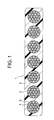
- FIG 1 is a cross section of an elevator rope according to Embodiment 1 of the present invention.
- a belt-shaped rope main body 1 has: seven strands 2; and a coating body 3 made of a resin for covering and integrating the strands 2.
- Each of the strands 2 has a plurality of steel wires 4.
- the wires 4 are laid parallel to each other (See Japanese Industrial Standards (JIS) G 3525 12.2 b). All of the wires 4 are laid parallel in all of the strands 2.
- the strands 2 are disposed side by side in a cross section perpendicular to a longitudinal direction of the rope main body 1 ( Figure 1).
- the seven strands 2 are disposed so as to line up in a straight line at a distance from each other in a width direction of the rope main body 1 (left-to-right in Figure 1) in the cross section perpendicular to the longitudinal direction of the rope main body 1.
- a diameter of the wires 4 is made approximately 1/400 of a diameter of a sheave (not shown) around which the rope main body 1 is wound. In this manner, bending stresses generated by the sheave are reduced, enabling fatigue resistance to be improved. Furthermore, in order to avoid making the diameter of the wires 4 considerably slenderer, it is preferable for the cross-sectional construction of the strands 2 to be a Warrington type rather than a Seale type or a filler wire type as defined in JIS G 3525.
- the coating body 3 is composed of a thermoplastic ether-based polyurethane resin, for example.
- An adhesive 5 is applied to at least an outer peripheral portion of each of the strands 2 to integrate the strands 2 with the coating body 3. That is, the strands 2 and the coating body 3 are bonded to each other by means of the adhesive 5. Timing of the application of the adhesive 5 may be either before or after the laying together of the wires 4.
- the wires 4 constituting each of the strands 2 are laid parallel to each other, the wires 4 are in line contact with each other and restrain each other. Consequently, contact pressure among the wires 4 is reduced, making internal friction less likely to occur in the strands 2, thereby also enabling stable strength to be ensured and also enabling extension of service life.
- the strands 2 will break in descending order of magnitude of load burden, or in descending order of severity of damage. In regard to this, even if the number of strands 2 is increased as a preventive measure, a strength increase proportional to the number of strands 2 cannot be expected since it is difficult to make the load burden on each of the strands 2 uniform.
- the residual strength at the point in time when JIS replacement criteria are reached is in the order of a 5 percent (5%) reduction from a standard value since a safety margin from a standard breaking load is provided.
- the material of the coating body 3 is not limited to a thermoplastic ether-based polyurethane resin, and appropriate selection in response to service conditions is possible. However, if used in a high-temperature, high-humidity environment, a hard ether-based polyurethane, in which hydrolysis is less likely to occur, is preferable to an ester-based polyurethane, in which hydrolysis occurs easily.
- FIG. 2 is a cross section of an elevator rope according to Embodiment 2 of the present invention.
- a belt-shaped rope main body 11 has: seven strand assemblies 12; and a coating body 13 made of a resin for covering and integrating the strand assemblies 12.
- the strand assemblies 12 are disposed side by side in a cross section perpendicular to a longitudinal direction of the rope main body 11.
- the seven strand assemblies 12 are disposed so as to line up in a straight line at a distance from each other in a width direction of the rope main body 11 in a cross section perpendicular to the longitudinal direction of the rope main body 11.
- Each of the strand assemblies 12 respectively includes: a core member 14 made of a resin extending in a longitudinal direction of the rope main body 11; and three strands 15 disposed around the core member 14 and laid together with the core member 14.
- Each of the strands 15 has a plurality of steel wires 16. The wires 16 are laid parallel to each other. All of the wires 16 are laid parallel in all of the strands 15.
- each of the strand assemblies 12 the three strands 15 are disposed in a triangular cross-sectional shape around the core member 14.
- the strand assemblies 12 are disposed such that the disposed cross-sectional shapes of the strands 15 are alternately reversed in direction.
- thermoplastic resin such as a polypropylene resin, a polyethylene resin, or a vinyl, etc., or synthetic resin fibers such as high-strength aramid fibers or polypropylene fibers, etc., laid together at a high density, for example, can be used for the material of the core member 14.
- An adhesive 5 is applied to at least an outer peripheral portion of each of the strands 15 to integrate them with the coating body 13. That is, the strands 15 and the coating body 13 are bonded to each other by means of the adhesive 5.
- the strand assemblies 12 are constituted by a core member 14 and three strands 15, slenderer wires 16 can be used, enabling reductions in a diameter of a sheave to which the present invention is applied.
- the strand assemblies 12 can be disposed at a high density, enabling strength to be increased while keeping the width of the rope main body 11 small, thereby enabling reductions in a width of a sheave to which the present invention is applied.
- Figure 3 is a cross section of an elevator rope according to Embodiment 3 of the present invention.
- strands 18 are used that include: a steel core wire 16 functioning as a wire; and six outer peripheral wires 17 functioning as wires disposed around the core wire 16 and laid parallel to each other. The rest of the construction is similar to that of Embodiment 2.
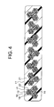
- Figure 4 is a cross section of an elevator rope according to Embodiment 4 of the present invention.
- a coating body 21 made of a rubber is used. Adhesive is not applied to the strands 18, and a film 22 is instead formed on outer peripheral portions of the core wire 16 and the outer peripheral wires 17 by a Parker process such as a phosphate film process or a galvanizing process, etc.
- the rest of the construction is similar to that of Embodiment 3.
Landscapes
- Ropes Or Cables (AREA)
- Lift-Guide Devices, And Elevator Ropes And Cables (AREA)
Abstract
Description
Claims (10)
- An elevator rope for suspending an elevator car, comprising a belt-shaped rope main body,
wherein:said rope main body has a plurality of strands in which a plurality of wires are laid parallel; and a coating body made of a resin for covering and integrating said strands; andsaid strands are disposed side by side in a cross section perpendicular to a longitudinal direction of said rope main body. - The elevator rope according to Claim 1, wherein all of said wires in all of said strands are laid parallel.
- The elevator rope according to Claim 1, wherein said wires are made of a steel, said coating body is made of a thermoplastic ether-based polyurethane resin, and said strands and said coating body are bonded to each other by means of an adhesive.
- The elevator rope according to Claim 1, wherein seven of said strands are disposed so as to line up in a straight line at a distance from each other in said cross section perpendicular to said longitudinal direction of said rope main body.
- An elevator rope for suspending an elevator car, comprising a belt-shaped rope main body,
wherein:said rope main body has:a plurality of strand assemblies including a core member made of a resin extending in a longitudinal direction of said rope main body, and a plurality of strands disposed around said core member and laid together with said core member; anda coating body made of a resin for covering and integrating said strand assemblies;said strands include a plurality of wires laid parallel to each other; andsaid strand assemblies are disposed side by side in a cross section perpendicular to a longitudinal direction of said rope main body. - The elevator rope according to Claim 5, wherein said core member is made of a polyethylene resin.
- The elevator rope according to Claim 5, wherein said core member is made of a synthetic resin fiber.
- The elevator rope according to Claim 5, wherein:each of said strand assemblies has one of said core member and three of said strands disposed around said core member in a triangular cross-sectional shape; andsaid strand assemblies are disposed such that said disposed cross-sectional shapes of said strands are alternately reversed in direction.
- The elevator rope according to Claim 5, wherein each of said strands includes a steel core wire functioning as one of said wires; and six outer peripheral wires functioning as said wires disposed around said core wire.
- The elevator rope according to Claim 5, wherein said coating body is made of a rubber, and a film is formed on an outer peripheral portion of said wires by a Parker process.
Applications Claiming Priority (1)
| Application Number | Priority Date | Filing Date | Title |
|---|---|---|---|
| PCT/JP2002/011108 WO2004037702A1 (en) | 2002-10-25 | 2002-10-25 | Rope for elevator |
Publications (3)
| Publication Number | Publication Date |
|---|---|
| EP1555233A1 true EP1555233A1 (en) | 2005-07-20 |
| EP1555233A4 EP1555233A4 (en) | 2011-05-11 |
| EP1555233B1 EP1555233B1 (en) | 2018-06-06 |
Family
ID=32170786
Family Applications (1)
| Application Number | Title | Priority Date | Filing Date |
|---|---|---|---|
| EP02777961.0A Expired - Lifetime EP1555233B1 (en) | 2002-10-25 | 2002-10-25 | Rope for elevator |
Country Status (5)
| Country | Link |
|---|---|
| EP (1) | EP1555233B1 (en) |
| JP (1) | JP4292151B2 (en) |
| KR (1) | KR100680926B1 (en) |
| CN (1) | CN1289378C (en) |
| WO (1) | WO2004037702A1 (en) |
Cited By (12)
| Publication number | Priority date | Publication date | Assignee | Title |
|---|---|---|---|---|
| WO2010072690A1 (en) * | 2008-12-22 | 2010-07-01 | Inventio Ag | Elevator support means, manufacturing method for said support means and elevator system comprising said elevator support means |
| US20120325590A1 (en) * | 2010-04-12 | 2012-12-27 | Kone Corporation | Elevator |
| US20130118838A1 (en) * | 2010-05-28 | 2013-05-16 | Kone Corporation | Method and elevator arrangement |
| US20140224592A1 (en) * | 2013-02-14 | 2014-08-14 | Kone Corporation | Elevator |
| US20140231179A1 (en) * | 2011-11-28 | 2014-08-21 | Kone Corporation | Elevator arrangement and method |
| EP2688827A4 (en) * | 2011-03-21 | 2014-11-19 | Otis Elevator Co | Elevator tension member |
| CN104179050A (en) * | 2014-08-19 | 2014-12-03 | 浙江西传电气科技有限公司 | Flat wire rope core elevator belt |
| AU2009204744B2 (en) * | 2008-01-18 | 2015-09-03 | Kone Corporation | Rope for a hoisting machine, elevator and use |
| WO2019002162A1 (en) | 2017-06-27 | 2019-01-03 | Bekaert Advanced Cords Aalter Nv | A reinforcement strand for reinforcing a polymer article |
| WO2019002163A1 (en) | 2017-06-27 | 2019-01-03 | Bekaert Advanced Cords Aalter Nv | Belt reinforced with steel strands |
| US20200039791A1 (en) * | 2018-08-06 | 2020-02-06 | Otis Elevator Company | Belt with layered load bearing elements |
| CN117645223A (en) * | 2022-09-02 | 2024-03-05 | 奥的斯电梯公司 | Elevator load bearing member with conductive adhesive |
Families Citing this family (17)
| Publication number | Priority date | Publication date | Assignee | Title |
|---|---|---|---|---|
| JP2009515796A (en) * | 2005-11-14 | 2009-04-16 | オーチス エレベータ カンパニー | Elevator load bearing member having chemical coating on tension member |
| CN101122097B (en) * | 2006-08-11 | 2011-11-16 | 因温特奥股份公司 | Belt for a lift facility and lift facility with a such belt |
| CN101324033B (en) * | 2007-06-15 | 2012-09-05 | 上海三菱电梯有限公司 | Stretching assembly of elevator apparatus |
| CN101343841B (en) * | 2007-07-09 | 2012-09-05 | 上海三菱电梯有限公司 | Stretching component of elevator and elevator device |
| CN101343840B (en) * | 2007-07-09 | 2012-12-12 | 上海三菱电梯有限公司 | Stretching component of elevator and elevator device |
| CN101372814B (en) * | 2007-08-24 | 2012-10-03 | 上海三菱电梯有限公司 | Cable of elevator apparatus and elevator apparatus |
| CN101456510B (en) * | 2007-12-14 | 2010-09-15 | 上海三菱电梯有限公司 | Elevator device |
| JP2009167545A (en) * | 2008-01-11 | 2009-07-30 | Toshiba Elevator Co Ltd | Wire rope |
| CN103261076B (en) * | 2010-12-22 | 2016-02-17 | 奥的斯电梯公司 | Elevator suspension and/or driven unit |
| RU2553967C2 (en) | 2011-04-14 | 2015-06-20 | Отис Элевэйтор Компани | Coated rope or belt for lifting systems |
| CN104724577A (en) * | 2013-12-18 | 2015-06-24 | 黄立成 | Elevator system with traction components featuring in signal transmission and traction drive |
| CN104444729A (en) * | 2014-11-04 | 2015-03-25 | 黄立成 | Triune elevator traction system |
| CN104452373A (en) * | 2014-11-26 | 2015-03-25 | 胡国良 | Drag rope and drag rope preparation method |
| EP3243785B1 (en) * | 2016-05-11 | 2021-04-07 | KONE Corporation | Rope, elevator arrangement and elevator |
| KR102623964B1 (en) * | 2017-04-20 | 2024-01-11 | 오티스 엘리베이터 컴파니 | Elevator system belt with fabric tension member |
| US10669126B2 (en) * | 2017-08-28 | 2020-06-02 | Otis Elevator Company | Fiber belt for elevator system |
| CN110130131B (en) * | 2019-05-15 | 2024-02-06 | 中国恩菲工程技术有限公司 | Mine hoisting composite belt |
Family Cites Families (12)
| Publication number | Priority date | Publication date | Assignee | Title |
|---|---|---|---|---|
| JP2876140B2 (en) * | 1990-02-27 | 1999-03-31 | 東京製綱株式会社 | Wire rope for moving cable |
| JP2510364B2 (en) * | 1991-06-24 | 1996-06-26 | 神鋼鋼線工業株式会社 | Coating method and coating equipment for long linear materials |
| CZ282660B6 (en) * | 1994-03-02 | 1997-08-13 | Inventio Ag | Bearer rope of lifting and transport facilities |
| JPH1018190A (en) * | 1996-07-04 | 1998-01-20 | Tokyo Seiko Co Ltd | Wire rope |
| AU7890098A (en) * | 1996-12-30 | 1998-07-31 | Kone Corporation | Elevator rope arrangement |
| US6401871B2 (en) * | 1998-02-26 | 2002-06-11 | Otis Elevator Company | Tension member for an elevator |
| WO1999043593A1 (en) | 1998-02-26 | 1999-09-02 | Otis Elevator Company | Elevator system with overhead drive motor |
| PT2284111E (en) * | 1998-12-22 | 2013-07-19 | Otis Elevator Co | Tension member for an elevator |
| DE29924774U1 (en) | 1998-12-22 | 2005-07-07 | Otis Elevator Co., Farmington | Tension member for providing lifting force to car of elevator system includes cords formed from metallic material encased within coating layer formed from non-metallic material |
| ZA200002574B (en) * | 1999-06-11 | 2000-12-01 | Inventio Ag | Synthetic fiber rope to be driven by a rope sheave. |
| BR0013514B1 (en) * | 1999-08-26 | 2011-11-01 | tension member for providing a lifting force for a car of an elevator system. | |
| WO2001086058A1 (en) * | 2000-05-08 | 2001-11-15 | N.V. Bekaert S.A. | Zinc-coated steel cord with improved fatigue resistance |
-
2002
- 2002-10-25 EP EP02777961.0A patent/EP1555233B1/en not_active Expired - Lifetime
- 2002-10-25 WO PCT/JP2002/011108 patent/WO2004037702A1/en not_active Ceased
- 2002-10-25 CN CNB028189418A patent/CN1289378C/en not_active Expired - Lifetime
- 2002-10-25 KR KR1020047008421A patent/KR100680926B1/en not_active Expired - Fee Related
- 2002-10-25 JP JP2004525630A patent/JP4292151B2/en not_active Expired - Fee Related
Cited By (27)
| Publication number | Priority date | Publication date | Assignee | Title |
|---|---|---|---|---|
| US10843900B2 (en) | 2008-01-18 | 2020-11-24 | Kone Corporation | Rope for a hoisting device, elevator and use |
| US11565912B2 (en) | 2008-01-18 | 2023-01-31 | Kone Corporation | Rope for a hoisting device, elevator and use |
| US9828214B2 (en) * | 2008-01-18 | 2017-11-28 | Kone Corporation | Synthetic fiber rope for hoisting in an elevator |
| AU2009204744B2 (en) * | 2008-01-18 | 2015-09-03 | Kone Corporation | Rope for a hoisting machine, elevator and use |
| CN102264623A (en) * | 2008-12-22 | 2011-11-30 | 因温特奥股份公司 | Elevator support means, manufacturing method for said support means and elevator system comprising said elevator support means |
| CN102264623B (en) * | 2008-12-22 | 2013-09-04 | 因温特奥股份公司 | Elevator support means, manufacturing method for said support means and elevator system comprising said elevator support means |
| WO2010072690A1 (en) * | 2008-12-22 | 2010-07-01 | Inventio Ag | Elevator support means, manufacturing method for said support means and elevator system comprising said elevator support means |
| US20120325590A1 (en) * | 2010-04-12 | 2012-12-27 | Kone Corporation | Elevator |
| US9676595B2 (en) * | 2010-05-28 | 2017-06-13 | Kone Corporation | Method and elevator arrangement |
| US20130118838A1 (en) * | 2010-05-28 | 2013-05-16 | Kone Corporation | Method and elevator arrangement |
| EP2688827A4 (en) * | 2011-03-21 | 2014-11-19 | Otis Elevator Co | Elevator tension member |
| US20140231179A1 (en) * | 2011-11-28 | 2014-08-21 | Kone Corporation | Elevator arrangement and method |
| US10227212B2 (en) * | 2011-11-28 | 2019-03-12 | Kone Corporation | Elevator arrangement and method |
| US10005642B2 (en) * | 2013-02-14 | 2018-06-26 | Kone Corporation | Elevator and elevator rope |
| US20140224592A1 (en) * | 2013-02-14 | 2014-08-14 | Kone Corporation | Elevator |
| CN104179050B (en) * | 2014-08-19 | 2016-08-24 | 浙江西传电气科技有限公司 | A kind of flat rope core elevator belt |
| CN104179050A (en) * | 2014-08-19 | 2014-12-03 | 浙江西传电气科技有限公司 | Flat wire rope core elevator belt |
| US11186947B2 (en) | 2017-06-27 | 2021-11-30 | Bekaert Advanced Cords Aalter Nv | Reinforcement strand for reinforcing a polymer article |
| WO2019002163A1 (en) | 2017-06-27 | 2019-01-03 | Bekaert Advanced Cords Aalter Nv | Belt reinforced with steel strands |
| US11685633B2 (en) | 2017-06-27 | 2023-06-27 | Bekaert Advanced Cords Aalter Nv | Belt reinforced with steel strands |
| US11708665B2 (en) | 2017-06-27 | 2023-07-25 | Bekaert Advanced Cords Aalter Nv | Reinforcement strand for reinforcing a polymer article |
| WO2019002162A1 (en) | 2017-06-27 | 2019-01-03 | Bekaert Advanced Cords Aalter Nv | A reinforcement strand for reinforcing a polymer article |
| US20200039791A1 (en) * | 2018-08-06 | 2020-02-06 | Otis Elevator Company | Belt with layered load bearing elements |
| US11591186B2 (en) * | 2018-08-06 | 2023-02-28 | Otis Elevator Company | Belt with layered load bearing elements |
| US12180040B2 (en) | 2018-08-06 | 2024-12-31 | Otis Elevator Company | Belt with layered load bearing elements |
| CN117645223A (en) * | 2022-09-02 | 2024-03-05 | 奥的斯电梯公司 | Elevator load bearing member with conductive adhesive |
| EP4332045A1 (en) * | 2022-09-02 | 2024-03-06 | OTIS Elevator Company | Elevator load bearing member with conductive adhesive |
Also Published As
| Publication number | Publication date |
|---|---|
| EP1555233B1 (en) | 2018-06-06 |
| EP1555233A4 (en) | 2011-05-11 |
| WO2004037702A1 (en) | 2004-05-06 |
| CN1558865A (en) | 2004-12-29 |
| JP4292151B2 (en) | 2009-07-08 |
| CN1289378C (en) | 2006-12-13 |
| KR100680926B1 (en) | 2007-02-08 |
| WO2004037702A9 (en) | 2004-12-02 |
| KR20040068177A (en) | 2004-07-30 |
| JPWO2004037702A1 (en) | 2006-02-23 |
Similar Documents
| Publication | Publication Date | Title |
|---|---|---|
| EP1555233B1 (en) | Rope for elevator | |
| CA2290130C (en) | Sheathless synthetic fiber rope | |
| EP1586526B1 (en) | Elevator rope | |
| EP1060305B2 (en) | Elevator Systems | |
| KR101088834B1 (en) | Synthetic fiber rope for crane and manufacturing method thereof | |
| CA1247471A (en) | Rope | |
| EP1561719B1 (en) | Rope for elevator and elevator equipment | |
| JP6016928B2 (en) | Load bearing assembly with steel rope and jacket | |
| KR101665837B1 (en) | Elevator rope | |
| US9902594B2 (en) | Elevator rope and elevator apparatus that uses same | |
| EP2634130A1 (en) | Rope for elevator | |
| JPH07150491A (en) | Hoist cable | |
| EP1312574B1 (en) | Synthetic fiber rope for elevators | |
| CN110799438A (en) | Belt reinforced with strands | |
| EP1371597B1 (en) | Main cable of elevator | |
| CN118202111A (en) | Ropes and Hoists | |
| RU2533960C1 (en) | Hoist suspending and/or driving assembly having at least one surface providing traction or creation of adhesive forces and containing open-laid weaving fibres | |
| EP1329413A1 (en) | Hoisting rope | |
| CN116323458B (en) | Elevator rope and method for manufacturing same | |
| EP2511219A1 (en) | Rope for elevator | |
| JP2002060163A (en) | Fiber rope for elevator | |
| CN116348407B (en) | Elevator ropes | |
| RS66023B1 (en) | Wire cable as a traction cable for elevators | |
| UA77130C2 (en) | Compound metal cord | |
| HK1185328B (en) | Elongated elevator load bearing member of a traction elevator system and method of making the same |
Legal Events
| Date | Code | Title | Description |
|---|---|---|---|
| PUAI | Public reference made under article 153(3) epc to a published international application that has entered the european phase |
Free format text: ORIGINAL CODE: 0009012 |
|
| 17P | Request for examination filed |
Effective date: 20040504 |
|
| AK | Designated contracting states |
Kind code of ref document: A1 Designated state(s): AT BE BG CH CY CZ DE DK EE ES FI FR GB GR IE IT LI LU MC NL PT SE SK TR |
|
| AX | Request for extension of the european patent |
Extension state: AL LT LV MK RO SI |
|
| DAX | Request for extension of the european patent (deleted) | ||
| RBV | Designated contracting states (corrected) |
Designated state(s): DE GB |
|
| RAP1 | Party data changed (applicant data changed or rights of an application transferred) |
Owner name: MITSUBISHI DENKI KABUSHIKI KAISHA |
|
| A4 | Supplementary search report drawn up and despatched |
Effective date: 20110412 |
|
| 17Q | First examination report despatched |
Effective date: 20110801 |
|
| REG | Reference to a national code |
Ref country code: DE Ref legal event code: R079 Ref document number: 60249466 Country of ref document: DE Free format text: PREVIOUS MAIN CLASS: B66B0007060000 Ipc: D07B0001220000 |
|
| GRAP | Despatch of communication of intention to grant a patent |
Free format text: ORIGINAL CODE: EPIDOSNIGR1 |
|
| RIC1 | Information provided on ipc code assigned before grant |
Ipc: B66B 7/06 20060101ALI20180131BHEP Ipc: D07B 1/22 20060101AFI20180131BHEP |
|
| INTG | Intention to grant announced |
Effective date: 20180226 |
|
| RIN1 | Information on inventor provided before grant (corrected) |
Inventor name: HONDA, TAKENOBU |
|
| GRAS | Grant fee paid |
Free format text: ORIGINAL CODE: EPIDOSNIGR3 |
|
| GRAA | (expected) grant |
Free format text: ORIGINAL CODE: 0009210 |
|
| AK | Designated contracting states |
Kind code of ref document: B1 Designated state(s): DE GB |
|
| REG | Reference to a national code |
Ref country code: GB Ref legal event code: FG4D |
|
| REG | Reference to a national code |
Ref country code: DE Ref legal event code: R096 Ref document number: 60249466 Country of ref document: DE |
|
| RIC2 | Information provided on ipc code assigned after grant |
Ipc: D07B 1/22 20060101AFI20180131BHEP Ipc: B66B 7/06 20060101ALI20180131BHEP |
|
| REG | Reference to a national code |
Ref country code: DE Ref legal event code: R097 Ref document number: 60249466 Country of ref document: DE |
|
| PLBE | No opposition filed within time limit |
Free format text: ORIGINAL CODE: 0009261 |
|
| STAA | Information on the status of an ep patent application or granted ep patent |
Free format text: STATUS: NO OPPOSITION FILED WITHIN TIME LIMIT |
|
| 26N | No opposition filed |
Effective date: 20190307 |
|
| GBPC | Gb: european patent ceased through non-payment of renewal fee |
Effective date: 20181025 |
|
| PG25 | Lapsed in a contracting state [announced via postgrant information from national office to epo] |
Ref country code: GB Free format text: LAPSE BECAUSE OF NON-PAYMENT OF DUE FEES Effective date: 20181025 |
|
| PGFP | Annual fee paid to national office [announced via postgrant information from national office to epo] |
Ref country code: DE Payment date: 20210914 Year of fee payment: 20 |
|
| REG | Reference to a national code |
Ref country code: DE Ref legal event code: R071 Ref document number: 60249466 Country of ref document: DE |