EP1555231A1 - Transporter for depositing sheet material on a tray, printer provided with such a transporter as well as a method for depositing a sheet material on a tray - Google Patents
Transporter for depositing sheet material on a tray, printer provided with such a transporter as well as a method for depositing a sheet material on a tray Download PDFInfo
- Publication number
- EP1555231A1 EP1555231A1 EP05100008A EP05100008A EP1555231A1 EP 1555231 A1 EP1555231 A1 EP 1555231A1 EP 05100008 A EP05100008 A EP 05100008A EP 05100008 A EP05100008 A EP 05100008A EP 1555231 A1 EP1555231 A1 EP 1555231A1
- Authority
- EP
- European Patent Office
- Prior art keywords
- roller
- belt
- rollers
- transporter
- sheet material
- Prior art date
- Legal status (The legal status is an assumption and is not a legal conclusion. Google has not performed a legal analysis and makes no representation as to the accuracy of the status listed.)
- Withdrawn
Links
- 238000000034 method Methods 0.000 title claims abstract description 18
- 238000000151 deposition Methods 0.000 title claims abstract description 10
- 238000006073 displacement reaction Methods 0.000 description 5
- 238000005096 rolling process Methods 0.000 description 3
- 238000010276 construction Methods 0.000 description 2
Images
Classifications
-
- B—PERFORMING OPERATIONS; TRANSPORTING
- B65—CONVEYING; PACKING; STORING; HANDLING THIN OR FILAMENTARY MATERIAL
- B65H—HANDLING THIN OR FILAMENTARY MATERIAL, e.g. SHEETS, WEBS, CABLES
- B65H29/00—Delivering or advancing articles from machines; Advancing articles to or into piles
- B65H29/26—Delivering or advancing articles from machines; Advancing articles to or into piles by dropping the articles
- B65H29/36—Delivering or advancing articles from machines; Advancing articles to or into piles by dropping the articles from tapes, bands, or rollers rolled from under the articles
Definitions
- the invention relates to a transporter for depositing sheet material on a tray, which transporter comprises at least two rollers which can be displaced with respect to each other, whilst a belt extends between said rollers above said tray.
- the invention furthermore relates to a printer provided with such a transporter.
- the invention also relates to a method for depositing a sheet material on a tray by means of a transporter comprising at least two rollers which can be displaced with respect to each other whilst a belt extends between said rollers above said tray.
- an endless belt is located around a relatively large number of rollers, whereby two rollers can be displaced with respect to each other.
- a first roller is located relatively close to a second roller, whereby a first end of sheet material is being deposited on the belt extending between said two rollers.
- the first roller is being displaced away from the second roller, whereby the sheet material is being supported as well as transported by said belt.
- the first roller is being displaced back to the second roller, whereby the sheet material is being deposited on said tray.
- the endless belt is being guided along several deflection rollers being movable in a vertical direction for the purpose of length equalisation between the first and second roller as well as for tensioning the belt.
- the transporter Due to said vertically displaceable rollers, the transporter has a relatively large height. Furthermore the vertically displaceable rollers makes the construction of the transporter relatively complicated.
- the transporter in that the belt is connected with ends to said two rollers, whereby the belt can be rolled up on and unrolled from at least one of said rollers.
- the belt Since the belt is being rolled up on and unrolled from at least one of said rollers, the length equalisation during displacement of the rollers with respect to each other as well as the tensioning of the belt will be taken care of by means of the same roller between which the belt extends on which the sheet material is temporarily being deposited during transport to the tray.
- An embodiment of the transporter according to the invention is characterized in that the belt can be rolled up and unrolled from both rollers.
- the belt can be rolled up and unrolled from the rollers in any desirable manner.
- a further embodiment of the transporter according to the invention is characterized in that the belt is a wire.
- a further embodiment of the transporter according to the invention is characterized in that the rollers and the belt extending between the rollers can be rotated together around an axis extending perpendicular to the longitudinal axis of the belt and the central axes of the rollers.
- the rollers after rotating over 180°, the rollers will be exchanged, whereby the first roller has become the second roller and the second roller has become the first roller. If in the initial position the belt is being rolled up on the first roller and needs to be rolled up on the second roller, this can be achieved by exchanging the rollers with respect to each other by rotating them over 180°.
- Yet another embodiment of the transporter according to the invention is characterized in that one end of at least one roller is rotatably and displaceably located between two endless belts.
- the roller can be rotated as well as transported in two opposite directions by driving the endless belt either in the same or in opposite directions with the same or different velocities.
- the invention furthermore relates to a printer which is provided with such a transporter.
- printers relatively thin sheet material of paper on which a print is being applied, needs to be carefully deposited on a tray or on previously deposited sheets in said tray whereby sliding of a paper sheet with respect to another paper sheet is being prevented.
- the paper sheet on the belt as well as the previous paper sheet already deposited on the tray has, in case of an inkjet printer, additional time to dry on the belt so that the risk that the print on the paper sheet will be destroyed by a paper sheet deposited thereon will be reduced or even eliminated.
- the belt is connected with ends to said two rollers whereby the belt is rolled up on at least one of said rollers in an initial position of the two rollers, subsequently a first roller is being displaced with respect to a second roller, whereby the belt is being unrolled from at least one roller and the sheet material is being supported and transported by the belt until the first roller has received a predetermined end position, after which the first roller is being displaced back to the second roller whereby the belt is being rolled up on one of said rollers, whilst the sheet material is being deposited on said tray.
- the displacement of the rollers with respect to the others as well as the rolling up and unrolling of the belt from at least one of said rollers causes the displacement of the belt, the length equalisation during displacement of the rollers with respect to the others as well as the tensioning of the belt.
- An embodiment of the method according to the invention is characterized in that when the first roller is being displaced to the predetermined end position, the belt is being unrolled from said second roller.
- Yet another embodiment of the method according to the invention is characterized in that when the first roller is being displaced to the predetermined end position, the belt is slightly rolled up on the first roller.
- Another embodiment of the method according to the invention is characterized in that when the first roller is being displaced back to the second roller, the belt is being rolled up on the first roller.
- the roller By rolling up the belt on the first roller, the roller is rolling away underneath the sheet material whereby no forces are applied on the sheet material due to which the sheet material might curling up or being moved.
- Yet another embodiment of the method according to the invention is characterized in that near the initial position the belt is being unrolled from the first roller and rolled up on the second roller, before a new sheet material is being transported by said belt.
- the first roller can be displaced again from the second roller, whereby the belt is being unrolled from said second roller to transport a sheet material.
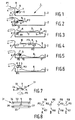
- Fig. 1 shows a transporter 1 according to the invention of a printer (not shown) which comprises a tray 2 located with one end 3 under a paper sheet guiding surface 4 of said printer.
- the transporter 1 is furthermore provided with at least two sets of two rollers 5, 6 and a belt 7 connected with ends to the rollers 5, 6.
- the roller 6 is rotatably mounted with respect to a frame (not shown) of said transporter 1 whilst the roller 5 is rotatably as well as displaceably with respect to the roller 6 mounted with respect to the frame (not shown).
- the belt 7 is fully rolled up on the roller 6 and the roller 5 is in the initial position.
- the first roller 5 is displaced in the direction indicated by arrow P2 until the roller 5 has reached the predetermined end position as shown in fig. 3. In this position the whole paper sheet 8 is supported by the belt 7 extending between the rollers 5, 6, whereby the first end 9 of the paper sheet 8 is located near the roller 5 whilst the opposite end 10 is located near the roller 6.
- the first roller 5 is being rotated in a clockwise direction indicated by arrow R2 due to which rotation, the belt 7 will be rolled up on the roller 5 whilst at the same time the roller 5 will be displaced to the roller 6 in a direction indicated by arrow P3, opposite to the direction indicated by arrow P2.
- the roller 6 will not be rotated.
- roller 5 Due to the movement of the roller 5, the roller will be rolled away underneath the paper sheet 8 without applying any force on the paper sheet 8. The first end 9 and afterwards the rest of the paper sheet 8 will now be deposited on the tray 2 (see fig. 5). The roller 5 will be rotated in the direction indicated by arrow R2 until the belt 7 is fully rolled up on the roller 5 and the roller 5 is in the initial position again.
- the belt 7 needs to be rolled up on the second roller 6 again to receive the start position as shown in fig. 1. Therefore, as shown in fig. 6 the rollers 5 and 6 are rotated anti clockwise in the directions indicated by arrows R3, R4 to unroll the belt 7 from the roller 5 whilst at the same time roll up the belt 7 on the roller 6.
- Fig. 7 shows a part of another transporter 21 of the invention whereby the rollers 5, 6 as well as the belt 7 are simultaneously rotatable around an axis 22 in a direction indicated by arrow R5, which axis 22 extends perpendicular to the central axes 23, 24 of the rollers 5, 6 as well as of the longitudinal direction of the belt 7.
- the roller 5, 6 as well as the belt 7 will be rotated over 180° in a direction indicated by arrow R5 in the situation as shown in fig. 5 whereby the whole belt 7 is being rolled up on the roller 5.
- the roller 5 will take up the former position of the roller 6 whilst the roller 6 will take up the former position of the roller 5.
- roller 5 provided with the belt 7 can now function as roller 6 whilst the empty roller 6 can now function as the roller 5.
- Fig. 8 shows a part 31 of the transporter 1 according to the invention whereby an end of the roller 5 is located between two endless belts 32, 33 which extend respectively around rollers 34, 35, 36, 37.
- Said rollers 34-37 are rotatably mounted with respect to a frame (not shown) of the transporter 1. If the rollers 35, 37 are being rotated in a respectively anti clockwise and clockwise direction indicated by the arrows R6, R7 the roller 5 will, due to friction with the belts 32, 33, be moved in the direction as indicated by arrow P2. If the rollers 35, 37 are both rotated anti clockwise indicated by the arrows R6, R8 the roller 5 will be rotated in a direction indicated by arrow R2.
- rollers 35, 36 are being rotated clockwise in a direction indicated by arrow R9, R8 the roller 5 will be rotated anti clockwise in a direction as indicated by arrow R3.
- the rollers 35, 37 are rotated clockwise and anti clockwise respectively as indicated by the arrows R9, R7, the roller 5 will be displaced in a direction indicated by arrow P3.
- the belt 7 might be slightly rolled up on the belt 5 in the situation as shown in fig. 2 due to which the end 9 of the paper sheet 8 will be pulled in the direction as indicted by arrow P2 whereby the paper sheet 8 will be straightened and be prevented from curling.
- rollers 5, 6 Preferably two or three sets of rollers 5, 6 are being provided whereby a wire type belt is connected to the rollers 5, 6.
- a wire type belt is connected to the rollers 5, 6.
- roller 6 is not being rotatable and forms a fixed connection with the printer, whereby the only rotatable roller is the roller 5.
- the roller 5 will then be rotated in a direction as indicated by arrow R3 (fig. 6) whilst simultaneously being displaced in a direction indicated by arrow P2.
- the sheet 8 will not automatically be transported by the belt 7 but needs to be pushed on the belt 7 by, for example the printer.
- roller 5 can be non-rotatable and roller 6 is rotatably connected t the printer.
Landscapes
- Engineering & Computer Science (AREA)
- Mechanical Engineering (AREA)
- Handling Of Continuous Sheets Of Paper (AREA)
Abstract
Description
- The invention relates to a transporter for depositing sheet material on a tray, which transporter comprises at least two rollers which can be displaced with respect to each other, whilst a belt extends between said rollers above said tray.
- The invention furthermore relates to a printer provided with such a transporter.
- The invention also relates to a method for depositing a sheet material on a tray by means of a transporter comprising at least two rollers which can be displaced with respect to each other whilst a belt extends between said rollers above said tray.
- By such a transporter and method which are known from US-A-4,681,003, an endless belt is located around a relatively large number of rollers, whereby two rollers can be displaced with respect to each other. In an initial position a first roller is located relatively close to a second roller, whereby a first end of sheet material is being deposited on the belt extending between said two rollers. From said initial position, the first roller is being displaced away from the second roller, whereby the sheet material is being supported as well as transported by said belt. As soon as the first roller has received a predetermined end position, the first roller is being displaced back to the second roller, whereby the sheet material is being deposited on said tray.
- When the first roller is being displaced with respect to the second roller, the endless belt is being guided along several deflection rollers being movable in a vertical direction for the purpose of length equalisation between the first and second roller as well as for tensioning the belt.
- Due to said vertically displaceable rollers, the transporter has a relatively large height. Furthermore the vertically displaceable rollers makes the construction of the transporter relatively complicated.
- It is an object of the invention to provide a transporter with a relatively simple configuration.
- This object is being achieved by the transporter according to the invention in that the belt is connected with ends to said two rollers, whereby the belt can be rolled up on and unrolled from at least one of said rollers.
- Since the belt is being rolled up on and unrolled from at least one of said rollers, the length equalisation during displacement of the rollers with respect to each other as well as the tensioning of the belt will be taken care of by means of the same roller between which the belt extends on which the sheet material is temporarily being deposited during transport to the tray.
- An embodiment of the transporter according to the invention is characterized in that the belt can be rolled up and unrolled from both rollers.
- In this manner the belt can be rolled up and unrolled from the rollers in any desirable manner.
- A further embodiment of the transporter according to the invention is characterized in that the belt is a wire.
- By means of a wire a relatively good support surface for a sheet material like a paper sheet is being provided whilst the contact surface between the wire and the sheet material is relatively small so that the risk of pollution of the wire and pollution of the sheet paper by the wire is easily being prevented.
- A further embodiment of the transporter according to the invention is characterized in that the rollers and the belt extending between the rollers can be rotated together around an axis extending perpendicular to the longitudinal axis of the belt and the central axes of the rollers.
- In this manner the rollers, after rotating over 180°, the rollers will be exchanged, whereby the first roller has become the second roller and the second roller has become the first roller. If in the initial position the belt is being rolled up on the first roller and needs to be rolled up on the second roller, this can be achieved by exchanging the rollers with respect to each other by rotating them over 180°.
- Yet another embodiment of the transporter according to the invention is characterized in that one end of at least one roller is rotatably and displaceably located between two endless belts.
- By means of those two endless belts, the roller can be rotated as well as transported in two opposite directions by driving the endless belt either in the same or in opposite directions with the same or different velocities.
- By means of said two endless belts a relatively simple construction for driving the roller is being achieved.
- The invention furthermore relates to a printer which is provided with such a transporter. Especially by printers, relatively thin sheet material of paper on which a print is being applied, needs to be carefully deposited on a tray or on previously deposited sheets in said tray whereby sliding of a paper sheet with respect to another paper sheet is being prevented. By depositing paper sheets on top of each other instead of sliding the paper sheets over each other, each paper sheet is being transported and deposited in the same manner on the tray which improves the predictability of the paper transport since the paper transport is no longer determined by the characteristics like type of material, amount of curl, etc. of previous paper sheets. Furthermore the paper sheet on the belt as well as the previous paper sheet already deposited on the tray has, in case of an inkjet printer, additional time to dry on the belt so that the risk that the print on the paper sheet will be destroyed by a paper sheet deposited thereon will be reduced or even eliminated.
- It is furthermore an object of the invention to provide a method for depositing a sheet material on a tray which is simpler and easier than the method according to the prior art.
- This object is achieved by the method according to the invention in that the belt is connected with ends to said two rollers whereby the belt is rolled up on at least one of said rollers in an initial position of the two rollers, subsequently a first roller is being displaced with respect to a second roller, whereby the belt is being unrolled from at least one roller and the sheet material is being supported and transported by the belt until the first roller has received a predetermined end position, after which the first roller is being displaced back to the second roller whereby the belt is being rolled up on one of said rollers, whilst the sheet material is being deposited on said tray.
- By the method according to the invention the displacement of the rollers with respect to the others as well as the rolling up and unrolling of the belt from at least one of said rollers, causes the displacement of the belt, the length equalisation during displacement of the rollers with respect to the others as well as the tensioning of the belt.
- An embodiment of the method according to the invention is characterized in that when the first roller is being displaced to the predetermined end position, the belt is being unrolled from said second roller.
- In this manner by displacing the first roller to the predetermined position also the belt is being displaced in a direction to the predetermined position, so that the sheet material supported by the belt will automatically be transported in said direction.
- Yet another embodiment of the method according to the invention is characterized in that when the first roller is being displaced to the predetermined end position, the belt is slightly rolled up on the first roller.
- In this manner a force is applied by the belt on the sheet material supported thereby, which tends to straighten the sheet material on the belt and prevents curling of the sheet material.
- Another embodiment of the method according to the invention is characterized in that when the first roller is being displaced back to the second roller, the belt is being rolled up on the first roller.
- By rolling up the belt on the first roller, the roller is rolling away underneath the sheet material whereby no forces are applied on the sheet material due to which the sheet material might curling up or being moved.
- Yet another embodiment of the method according to the invention is characterized in that near the initial position the belt is being unrolled from the first roller and rolled up on the second roller, before a new sheet material is being transported by said belt.
- After doing so, the first roller can be displaced again from the second roller, whereby the belt is being unrolled from said second roller to transport a sheet material.
- The invention will now be further explained with reference to the drawings in which:
- fig. 1-6 show schematically several steps of the method according to the invention for depositing a sheet material by a transporter according to the invention;
- fig. 7 shows schematically a part of another embodiment of a transporter according to the invention;
- fig. 8 shows schematically a part of a transporter according to the invention for rotating and displacing a roller.
-
- The same elements are provided with the same reference numbers in all the drawings.
- Fig. 1 shows a transporter 1 according to the invention of a printer (not shown) which comprises a
tray 2 located with one end 3 under a papersheet guiding surface 4 of said printer. The transporter 1 is furthermore provided with at least two sets of tworollers belt 7 connected with ends to therollers roller 6 is rotatably mounted with respect to a frame (not shown) of said transporter 1 whilst theroller 5 is rotatably as well as displaceably with respect to theroller 6 mounted with respect to the frame (not shown). In the situation as shown in fig. 1, thebelt 7 is fully rolled up on theroller 6 and theroller 5 is in the initial position. In said situation a sheet material like apaper sheet 8 on which a print is being applied, is moved by the printer in the direction indicated by arrow P1 to the transporter 1 so that afirst end 9 of thepaper sheet 8 will contact thebelt 7. As soon as theend 9 of thepaper sheet 8 is located on thebelt 7, thefirst roller 5 might be displaced from theroller 6 in a direction indicated by arrow P2, whereby thesecond roller 6 is rotated in a direction indicated by arrow R1 to unroll thebelt 7. By moving thefirst roller 5 in the direction indicated by arrow P2, also thebelt 7 as well as theend 9 of thepaper sheet 8 is being transported in said direction (fig. 2). Thefirst roller 5 is displaced in the direction indicated by arrow P2 until theroller 5 has reached the predetermined end position as shown in fig. 3. In this position thewhole paper sheet 8 is supported by thebelt 7 extending between therollers first end 9 of thepaper sheet 8 is located near theroller 5 whilst theopposite end 10 is located near theroller 6. To deposit thepaper sheet 8 on thetray 2 in which already depositedpaper sheets 8 may be present, thefirst roller 5 is being rotated in a clockwise direction indicated by arrow R2 due to which rotation, thebelt 7 will be rolled up on theroller 5 whilst at the same time theroller 5 will be displaced to theroller 6 in a direction indicated by arrow P3, opposite to the direction indicated by arrow P2. Theroller 6 will not be rotated. Due to the movement of theroller 5, the roller will be rolled away underneath thepaper sheet 8 without applying any force on thepaper sheet 8. Thefirst end 9 and afterwards the rest of thepaper sheet 8 will now be deposited on the tray 2 (see fig. 5). Theroller 5 will be rotated in the direction indicated by arrow R2 until thebelt 7 is fully rolled up on theroller 5 and theroller 5 is in the initial position again. - To be able to receive a
new paper sheet 8 on thebelt 7, to transport it and deposit it on thetray 2, thebelt 7 needs to be rolled up on thesecond roller 6 again to receive the start position as shown in fig. 1. Therefore, as shown in fig. 6 therollers belt 7 from theroller 5 whilst at the same time roll up thebelt 7 on theroller 6. - Fig. 7 shows a part of another
transporter 21 of the invention whereby therollers belt 7 are simultaneously rotatable around anaxis 22 in a direction indicated by arrow R5, whichaxis 22 extends perpendicular to thecentral axes rollers belt 7. By this embodiment of thetransporter 21 theroller belt 7 will be rotated over 180° in a direction indicated by arrow R5 in the situation as shown in fig. 5 whereby thewhole belt 7 is being rolled up on theroller 5. By rotating over 180°, theroller 5 will take up the former position of theroller 6 whilst theroller 6 will take up the former position of theroller 5. Due to said rotation, theroller 5 provided with thebelt 7 can now function asroller 6 whilst theempty roller 6 can now function as theroller 5. By this embodiment it is not necessary to unroll and roll up the belt as is necessary in the situation as shown in fig. 6 of the transporter 1. - Fig. 8 shows a
part 31 of the transporter 1 according to the invention whereby an end of theroller 5 is located between twoendless belts rollers rollers roller 5 will, due to friction with thebelts rollers roller 5 will be rotated in a direction indicated by arrow R2. If bothrollers roller 5 will be rotated anti clockwise in a direction as indicated by arrow R3. If therollers roller 5 will be displaced in a direction indicated by arrow P3. By rotating therollers roller 5 can easily be controlled. - If desired, the
belt 7 might be slightly rolled up on thebelt 5 in the situation as shown in fig. 2 due to which theend 9 of thepaper sheet 8 will be pulled in the direction as indicted by arrow P2 whereby thepaper sheet 8 will be straightened and be prevented from curling. - Preferably two or three sets of
rollers rollers long rollers belt 7 is also relatively wide and will support the paper sheet over the full surface. - It is also possible to use two sets of
rollers belts 7 are directed to each other and a sheet material like a paper sheet is being transported between the twobelts 7. - It is also possible that the
roller 6 is not being rotatable and forms a fixed connection with the printer, whereby the only rotatable roller is theroller 5. By the situation as shown in fig. 2 and 3, theroller 5 will then be rotated in a direction as indicated by arrow R3 (fig. 6) whilst simultaneously being displaced in a direction indicated by arrow P2. Thesheet 8 will not automatically be transported by thebelt 7 but needs to be pushed on thebelt 7 by, for example the printer. Alsoroller 5 can be non-rotatable androller 6 is rotatably connected t the printer. - It is also possible to use wires instead of belts.
- It is also possible to use only one set of
rollers belt 7 is relatively wide.
Claims (11)
- Transporter (1) for depositing sheet material (8) on a tray (2), which transporter (1) comprises at least two rollers (5, 6) which can be displaced with respect to each other, whilst a belt (7) extends between said rollers (5, 6) above said tray (2), characterized in that the belt (7) is connected with ends to said two rollers (5, 6), whereby the belt (7) can be rolled up on and unrolled from at least one of said rollers (5, 6).
- Transporter (1) according to claim 1, characterized in that the belt (7) can be rolled up and unrolled from both rollers (5, 6).
- Transporter (1) according to claim 1 or 2, characterized in that the belt (7) is a wire.
- Transporter (1) according to one of the preceding claims, characterized in that the rollers (5, 6) and the belt (7) extending between the rollers (5, 6) can be rotated together around an axis extending perpendicular to the longitudinal axis of the belt (7) and the central axes of the rollers (5, 6).
- Transporter (1) according to one of the preceding claims, characterized in that one end of at least one roller is rotatably and displaceably located between two endless belts (7).
- Printer provided with a transporter (1) according to one of the preceding claims.
- Method for depositing a sheet material (8) on a tray (2) by means of a transporter (1) comprising at least two rollers (5, 6) which can be displaced with respect to each other whilst a belt (7) extends between said rollers (5, 6) above said tray (2), characterized in that the belt (7) is connected with ends to said two rollers (5, 6), whereby the belt (7) is rolled up on at least one of said rollers (5, 6) in an initial position of the two rollers (5, 6), subsequently a first roller is being displaced with respect to a second roller, whereby the belt (7) is being unrolled from at least one roller and the sheet material (8) is being supported and transported by the belt (7) until the first roller has received a predetermined end position, after which the first roller is being displaced back to the second roller whereby the belt (7) is being rolled up on one of said rollers (5, 6), whilst the sheet material (8) is being deposited on said tray (2).
- Method according to claim 7, characterized in that when the first roller is being displaced to the predetermined end position, the belt (7) is being unrolled from said second roller.
- Method according to claim 7 or 8, characterized in that when the first roller is being displaced to the predetermined end position, the belt (7) is slightly rolled up on the first roller.
- Method according to one of the preceding claims 7-9, characterized in that when the first roller is being displaced back to the second roller, the belt (7) is being rolled up on the first roller.
- Method according to one of the preceding claims 7-10, characterized in that near the initial position the belt (7) is being unrolled from the first roller and rolled up on the second roller, before a new sheet material (8) is being transported by said belt (7).
Priority Applications (1)
| Application Number | Priority Date | Filing Date | Title |
|---|---|---|---|
| EP05100008A EP1555231A1 (en) | 2004-01-12 | 2005-01-03 | Transporter for depositing sheet material on a tray, printer provided with such a transporter as well as a method for depositing a sheet material on a tray |
Applications Claiming Priority (3)
| Application Number | Priority Date | Filing Date | Title |
|---|---|---|---|
| EP04075013 | 2004-01-12 | ||
| EP04075013 | 2004-01-12 | ||
| EP05100008A EP1555231A1 (en) | 2004-01-12 | 2005-01-03 | Transporter for depositing sheet material on a tray, printer provided with such a transporter as well as a method for depositing a sheet material on a tray |
Publications (1)
| Publication Number | Publication Date |
|---|---|
| EP1555231A1 true EP1555231A1 (en) | 2005-07-20 |
Family
ID=34621569
Family Applications (1)
| Application Number | Title | Priority Date | Filing Date |
|---|---|---|---|
| EP05100008A Withdrawn EP1555231A1 (en) | 2004-01-12 | 2005-01-03 | Transporter for depositing sheet material on a tray, printer provided with such a transporter as well as a method for depositing a sheet material on a tray |
Country Status (1)
| Country | Link |
|---|---|
| EP (1) | EP1555231A1 (en) |
Citations (5)
| Publication number | Priority date | Publication date | Assignee | Title |
|---|---|---|---|---|
| GB191311449A (en) * | 1913-05-16 | 1914-04-09 | George Mann & Company Ltd | Improvements in the Delivery Mechanism of Printing Machines. |
| DE364053C (en) * | 1920-09-02 | 1922-11-16 | Enrico Hanauer | Device for executing and depositing the sheets on printing machines |
| GB334438A (en) * | 1928-11-02 | 1930-09-04 | Maschf Augsburg Nuernberg Ag | Improvements in delivery devices for sheet printing machines, particularly intaglio sheet printing machines |
| CH359593A (en) * | 1960-04-28 | 1962-01-15 | Bobst Fils Sa J | Device making it possible to intercept sheets deposited one by one in a stack during distribution |
| US3411773A (en) * | 1965-05-26 | 1968-11-19 | Broadbent & Sons Ltd Thomas | Stacking devices |
-
2005
- 2005-01-03 EP EP05100008A patent/EP1555231A1/en not_active Withdrawn
Patent Citations (5)
| Publication number | Priority date | Publication date | Assignee | Title |
|---|---|---|---|---|
| GB191311449A (en) * | 1913-05-16 | 1914-04-09 | George Mann & Company Ltd | Improvements in the Delivery Mechanism of Printing Machines. |
| DE364053C (en) * | 1920-09-02 | 1922-11-16 | Enrico Hanauer | Device for executing and depositing the sheets on printing machines |
| GB334438A (en) * | 1928-11-02 | 1930-09-04 | Maschf Augsburg Nuernberg Ag | Improvements in delivery devices for sheet printing machines, particularly intaglio sheet printing machines |
| CH359593A (en) * | 1960-04-28 | 1962-01-15 | Bobst Fils Sa J | Device making it possible to intercept sheets deposited one by one in a stack during distribution |
| US3411773A (en) * | 1965-05-26 | 1968-11-19 | Broadbent & Sons Ltd Thomas | Stacking devices |
Similar Documents
| Publication | Publication Date | Title |
|---|---|---|
| DE60214649T2 (en) | Device for compensating the curvature of roll paper and recording apparatus with the device for compensating the curvature of roll paper | |
| CN101592885B (en) | Sheet discharge device and image forming apparatus | |
| JPS641382B2 (en) | ||
| DE60213720T2 (en) | Device for selecting and transporting printing plates | |
| JPH06329327A (en) | Thin sheet loading and receiving device | |
| JP4591273B2 (en) | Bookbinding apparatus and image forming system | |
| CN101445194B (en) | Slice material conveying device and image forming device | |
| JPH0520345B2 (en) | ||
| US7469888B2 (en) | Transporting device for depositing sheet material onto a tray, a printer provided with such a device and a method for depositing a sheet material onto a tray | |
| KR19980070633A (en) | Roll-up device | |
| EP0778235A3 (en) | Surface winder | |
| DE3805253A1 (en) | PAPER FEEDER FOR AN IMAGE GENERATOR | |
| DE102005002509A1 (en) | Handling and stacking system for printed paper sheets incorporates rows of guide rollers with angle adjustment on support beams on either side of sheet | |
| EP1108669A3 (en) | Reel winding device, in particular for a reel slitting machine | |
| US11383949B2 (en) | Medium loading device | |
| EP1661837A1 (en) | Sheet discharge system | |
| JP4426464B2 (en) | Coiler equipment for rolling strip | |
| DE60010581T2 (en) | Stencil printing machine. | |
| JP5059409B2 (en) | Web alignment apparatus and method | |
| JPH04164764A (en) | Curl correction mechanism and recording device having the curl correction mechanism | |
| NL1027493C2 (en) | Printer. | |
| DE1807936A1 (en) | Electrostatographic device | |
| JP3273449B2 (en) | Paper post-processing equipment | |
| DE202018103436U1 (en) | Device for automatic stacking of several flat objects rolling side by side | |
| JP3277465B2 (en) | Sheet distribution storage device |
Legal Events
| Date | Code | Title | Description |
|---|---|---|---|
| PUAI | Public reference made under article 153(3) epc to a published international application that has entered the european phase |
Free format text: ORIGINAL CODE: 0009012 |
|
| AK | Designated contracting states |
Kind code of ref document: A1 Designated state(s): AT BE BG CH CY CZ DE DK EE ES FI FR GB GR HU IE IS IT LI LT LU MC NL PL PT RO SE SI SK TR |
|
| AX | Request for extension of the european patent |
Extension state: AL BA HR LV MK YU |
|
| 17P | Request for examination filed |
Effective date: 20060120 |
|
| AKX | Designation fees paid |
Designated state(s): AT BE BG CH CY CZ DE DK EE ES FI FR GB GR HU IE IS IT LI LT LU MC NL PL PT RO SE SI SK TR |
|
| 17Q | First examination report despatched |
Effective date: 20070605 |
|
| STAA | Information on the status of an ep patent application or granted ep patent |
Free format text: STATUS: THE APPLICATION IS DEEMED TO BE WITHDRAWN |
|
| 18D | Application deemed to be withdrawn |
Effective date: 20090314 |