EP1555228A1 - Method and device for transferring packets - Google Patents
Method and device for transferring packets Download PDFInfo
- Publication number
- EP1555228A1 EP1555228A1 EP05100162A EP05100162A EP1555228A1 EP 1555228 A1 EP1555228 A1 EP 1555228A1 EP 05100162 A EP05100162 A EP 05100162A EP 05100162 A EP05100162 A EP 05100162A EP 1555228 A1 EP1555228 A1 EP 1555228A1
- Authority
- EP
- European Patent Office
- Prior art keywords
- row
- lead packet
- transfer
- packets
- lead
- Prior art date
- Legal status (The legal status is an assumption and is not a legal conclusion. Google has not performed a legal analysis and makes no representation as to the accuracy of the status listed.)
- Granted
Links
Images


Classifications
-
- B—PERFORMING OPERATIONS; TRANSPORTING
- B65—CONVEYING; PACKING; STORING; HANDLING THIN OR FILAMENTARY MATERIAL
- B65G—TRANSPORT OR STORAGE DEVICES, e.g. CONVEYORS FOR LOADING OR TIPPING, SHOP CONVEYOR SYSTEMS OR PNEUMATIC TUBE CONVEYORS
- B65G59/00—De-stacking of articles
- B65G59/02—De-stacking from the top of the stack
- B65G59/04—De-stacking from the top of the stack by suction or magnetic devices
-
- B—PERFORMING OPERATIONS; TRANSPORTING
- B65—CONVEYING; PACKING; STORING; HANDLING THIN OR FILAMENTARY MATERIAL
- B65G—TRANSPORT OR STORAGE DEVICES, e.g. CONVEYORS FOR LOADING OR TIPPING, SHOP CONVEYOR SYSTEMS OR PNEUMATIC TUBE CONVEYORS
- B65G47/00—Article or material-handling devices associated with conveyors; Methods employing such devices
- B65G47/52—Devices for transferring articles or materials between conveyors i.e. discharging or feeding devices
- B65G47/68—Devices for transferring articles or materials between conveyors i.e. discharging or feeding devices adapted to receive articles arriving in one layer from one conveyor lane and to transfer them in individual layers to more than one conveyor lane or to one broader conveyor lane, or vice versa, e.g. combining the flows of articles conveyed by more than one conveyor
- B65G47/71—Devices for transferring articles or materials between conveyors i.e. discharging or feeding devices adapted to receive articles arriving in one layer from one conveyor lane and to transfer them in individual layers to more than one conveyor lane or to one broader conveyor lane, or vice versa, e.g. combining the flows of articles conveyed by more than one conveyor the articles being discharged or distributed to several distinct separate conveyors or to a broader conveyor lane
-
- B—PERFORMING OPERATIONS; TRANSPORTING
- B65—CONVEYING; PACKING; STORING; HANDLING THIN OR FILAMENTARY MATERIAL
- B65G—TRANSPORT OR STORAGE DEVICES, e.g. CONVEYORS FOR LOADING OR TIPPING, SHOP CONVEYOR SYSTEMS OR PNEUMATIC TUBE CONVEYORS
- B65G2201/00—Indexing codes relating to handling devices, e.g. conveyors, characterised by the type of product or load being conveyed or handled
- B65G2201/02—Articles
- B65G2201/0235—Containers
- B65G2201/025—Boxes
Definitions
- the present invention relates to a method and device for transferring packets.
- the present invention may be used to advantage in cigarette packing, to which the following description refers purely by way of example.
- cigarette packing In cigarette packing, two superimposed, parallel rows of packets of cigarettes are fed to a cartoning machine for producing packages or cartons, each containing a group of two superimposed rows of packets of cigarettes; and, upstream from the cartoning machine, the packets of cigarettes fed to the cartoning machine are normally fed through one or more operating units (typically for heat-shrinking the plastic overwrapping of the packets of cigarettes), one of which usually comprises two parallel feed channels separated by partition members and each engaged by a respective row of packets.
- operating units typically for heat-shrinking the plastic overwrapping of the packets of cigarettes
- Transferring the rows of packets to the feed channels is a highly delicate operation, during which the two rows of packets may shift out of line, thus creating processing problems downstream from the operating unit, and/or the packets may undergo damage caused by improper insertion inside the channels.
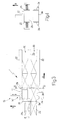
- Number 1 in Figure 1 indicates as a whole a device for transferring packets 2 of cigarettes (not shown), and which comprises a conveyor assembly 3 for conveying two rows 4 and 5 of packets 2 along a feed path P to an operating unit 6.
- Packets 2 are each wrapped in a respective overwrapping 7 of heat-shrink material, e.g. cellophane; and unit 6 heat-shrinks overwrappings 7 of heat-shrink material, and is located upstream from a known machine (not shown) for producing cartons (not shown) of packets 2.
- overwrapping 7 of heat-shrink material e.g. cellophane
- unit 6 heat-shrinks overwrappings 7 of heat-shrink material, and is located upstream from a known machine (not shown) for producing cartons (not shown) of packets 2.
- Conveyor assembly 3 comprises a transfer unit 8 for feeding rows 4 and 5, parallel to each other and in a given substantially horizontal direction A, to a transfer station 9; transfer unit 8 comprises a belt conveyor; and rows 4 and 5 are arranged, at transfer unit 8, one underneath the other and directly contacting each other.
- Conveyor assembly 3 also comprises a transfer unit 10 having a pusher 11 and a known actuator (not shown) for moving pusher 11 vertically.
- pusher 11 intercepts and pushes a packet 2a in row 4 upwards in a given substantially vertical direction B to a transfer station 12 located immediately upstream from unit 6 along path P; and, as it is pushed upwards, packet 2a lifts up an end packet 2b in row 5.
- a parting assembly 13 at transfer station 12 parts packets 2a and 2b in direction B, and comprises a positioning unit 14, which positions packet 2b correctly at transfer station 12, and in turn comprises a gripping head 15.
- Gripping head 15 comprises two gripping members 16, each of which is movable about a respective substantially horizontal hinge 17 and is held in position by a respective elastic member 18.
- Positioning unit 14 also comprises a known actuator (not shown) for moving gripping head 15 in direction B.
- gripping head 15 comprises suction cups.
- gripping head 15 is fixed, and, in use, once packet 2b is gripped by gripping head 15, pusher 11 is lowered to detach packet 2a from packet 2b.
- Conveyor assembly 3 also comprises a transfer unit 19 for transferring the parted packets 2a and 2b, in direction A, from transfer station 12 to respective feed channels 20 of unit 6, and which comprises a pusher 21, and a known actuator (not shown) for moving pusher 21 in direction A.
- Unit 6 comprises two conveyors 22 for conveying respective rows 4 and 5 along channels 20, which are substantially horizontal and separated by a partition member 23.
- Conveyors 22 and partition member 23 each comprise known heating plates (not shown) for heating packets 2 and so shrinking overwrappings 7 about packets 2.
- Figures 3 and 4 show an alternative embodiment of device 1, which comprises a known transfer unit (not shown) for conveying packets 2a and 2b, in direction A, along path P to transfer station 12 located upstream from unit 6.
- a known transfer unit (not shown) for conveying packets 2a and 2b, in direction A, along path P to transfer station 12 located upstream from unit 6.
- Parting assembly 13 comprises a positioning unit 14' located at transfer station 12 and in turn comprising a suction gripping head 15', and a known actuator (not shown) for moving gripping head 15' in direction B.
- Parting assembly 13 also comprises retaining members 24 for retaining packet 2a when, in use, packet 2b is gripped and raised by gripping head 15'; and elastic gripping members 25 located on opposite sides of gripping head 15', and which engage the lateral walls of packet 2b to clamp packet 2b in a given position.
- retaining members 24 comprise suction devices.
- packets 2a and 2b are parted, the packets 2'a and 2'b immediately upstream from packets 2a and 2b push packets 2a and 2b in direction B to unit 6.
Landscapes
- Engineering & Computer Science (AREA)
- Mechanical Engineering (AREA)
- Wrapping Of Specific Fragile Articles (AREA)
- Intermediate Stations On Conveyors (AREA)
- Control And Other Processes For Unpacking Of Materials (AREA)
- Branching, Merging, And Special Transfer Between Conveyors (AREA)
- Replacing, Conveying, And Pick-Finding For Filamentary Materials (AREA)
- Auxiliary Devices For And Details Of Packaging Control (AREA)
- Attitude Control For Articles On Conveyors (AREA)
Abstract
Description
Claims (22)
- A method of transferring packets, the method comprising conveying a first row (4) of packets (2) and at least a second row (5) of packets (2), substantially parallel to the first row (4), along a feed path (P) to an operating unit (6) having at least one pair of channels (20); and inserting each row (4, 5) inside a respective channel (20) of the operating unit (6) by transferring the row (4, 5) in a given first direction (A); the method being characterized by comprising a first transfer step to feed at least one lead packet (2a) in the first row (4) and at least one lead packet (2b) in the second row (5) to a first transfer station (12) located upstream from the operating unit (6) along the feed path (P); a parting step to part the two lead packets (2a, 2b), at the first transfer station (12), in a second direction (B) crosswise to the first direction (A); and a second transfer step, after the parting step, to feed each lead packet (2a, 2b) in the first direction (A) into the respective channel (20) of the operating unit (6).
- A method as claimed in Claim 1, and comprising a third transfer step to convey the first and the second row (4, 5), parallel to each other and in the first direction (A), to a second transfer station (9) located upstream from the first transfer station (12); during the first transfer step, the lead packet (2a) in the first row (4) and the lead packet (2b) in the second row (5) being conveyed from the second transfer station (9) to the first transfer station (12).
- A method as claimed in Claim 1, wherein, during the third transfer step, the first and the second row (4, 5) are in contact with each other.
- A method as claimed in Claim 1 or 2, wherein, during the first transfer step, the lead packets (2a, 2b) in the first and second row (4, 5) are conveyed in said second direction (B) by first push means (11).
- A method as claimed in Claim 4, wherein the first push means (11) push the lead packet (2a) in the first row (4), which in turn pushes the lead packet (2b) in the second row (5).
- A method as claimed in any one of Claims 1 to 5, wherein, during said first transfer step, the lead packet (2a) in the first row (4) is pushed and, in turn, pushes the lead packet (2b) in the second row (5) upwards in the second direction (B), which is substantially vertical; and, after positioning means (14), located at the first transfer station (12), have gripped the lead packet (2b) in the second row (5) during the parting step, the lead packet (2a) in the first row (4) is moved vertically downwards to detach itself from the lead packet (2b) in the second row (5).
- A method as claimed in any one of Claims 1 to 6, wherein second push means (21) are located at the first transfer station (12), and, during the second transfer step, convey each lead packet (2a, 2b), in the first direction (A), to a respective channel (20) of the operating unit (6).
- A method as claimed in Claim 1, wherein, during the first transfer step, the lead packet (2a) in the first row (4) and the lead packet (2b) in the second row (5) are conveyed in the first direction (A).
- A method as claimed in any one of Claims 1 to 8, wherein the first direction (A) is substantially horizontal, and the second direction (B) is substantially vertical.
- A method as claimed in any one of Claims 1 to 9, wherein positioning means (14), located at the first transfer station (12), grip the lead packet (2b) in the second row (5) during the parting step.
- A method as claimed in Claim 10, wherein the positioning means (14) move the lead packet (2b) in the second row (5) in the second direction (B) so as to detach the lead packet (2b) in the second row (5) from the lead packet (2a) in the first row (4).
- A device for transferring packets, the device comprising conveying means (3) for conveying a first row (4) of packets (2) and at least a second row (5) of packets (2), substantially parallel to the first row (4), along a feed path (P) to an operating unit (6) having at least one pair of channels (20), and for inserting each row (4, 5) inside a respective channel (20) of the operating unit (6) by transferring the row (4, 5) in a given first direction (A); the device (1) being characterized in that the conveying means (3) comprise first transfer means (10) for conveying at least one lead packet (2a) in the first row (4) and at least one lead packet (2b) in the second row (5) of packets to a first transfer station (12) located upstream from the operating unit (6) along the feed path (P); parting means (13) located at the first transfer station (12) to part the two lead packets (2a, 2b) in a given second direction (B); and second transfer means (19) for feeding the parted lead packets (2a, 2b), in the first direction (A), from the first transfer station (12) to the respective channels (20) of the operating unit (6).
- A device as claimed in Claim 12, wherein the conveying means (3) comprise third transfer means (8) for conveying the first and second row (4, 5), parallel to each other and in the first direction (A), to a second transfer station (9) located upstream from the first transfer station (12); the first transfer means (10) conveying the lead packet (2a) in the first row (4) and the lead packet (2b) in the second row (5) from the second transfer station (9) to the first transfer station (12).
- A device as claimed in Claim 12 or 13, wherein the third transfer means (8) keep the first and second row (4, 5) in contact with each other.
- A device as claimed in any one of Claims 12 to 14, wherein the first transfer means (10) comprise first push means (11) for conveying the lead packets (2a, 2b) in the first and second row (4, 5) in said second direction (B).
- A device as claimed in Claim 15, wherein said first push means (11) push the lead packet (2a) in the first row (4), which in turn pushes the lead packet (2b) in the second row (5).
- A device as claimed in Claim 12, wherein the first transfer means convey the lead packet (2a) in the first row (4) and the lead packet (2b) in the second row (5) in the first direction (A).
- A device as claimed in Claim 17, wherein the first and second transfer means are substantially coincident.
- A device as claimed in any one of Claims 12 to 18, wherein the parting means (13) comprise positioning means (14) for gripping the lead packet (2b) in the second row (5).
- A device as claimed in Claim 19, wherein the positioning means (14) move the lead packet (2b) in the second row (5) in the second direction (B) so as to detach the lead packet (2b) in the second row (5) from the lead packet (2a) in the first row (4).
- A device as claimed in any one of Claims 12 to 20, wherein the second transfer means (19) comprise second push means (21) located at the first transfer station (12), and which convey each lead packet (2a, 2b), in the first direction (A), to a respective channel (20) of the operating unit (6).
- A device as claimed in any one of Claims 12 to 21, wherein the first direction (A) is substantially horizontal, and the second direction (B) is substantially vertical.
Priority Applications (1)
| Application Number | Priority Date | Filing Date | Title |
|---|---|---|---|
| DE602005002757T DE602005002757T3 (en) | 2004-01-13 | 2005-01-12 | Method and device for transferring boxes |
Applications Claiming Priority (2)
| Application Number | Priority Date | Filing Date | Title |
|---|---|---|---|
| ITBO20040013 | 2004-01-13 | ||
| IT000013A ITBO20040013A1 (en) | 2004-01-13 | 2004-01-13 | METHOD AND DEVICE FOR THE TRANSFER OF PACKAGES |
Publications (3)
| Publication Number | Publication Date |
|---|---|
| EP1555228A1 true EP1555228A1 (en) | 2005-07-20 |
| EP1555228B1 EP1555228B1 (en) | 2007-10-10 |
| EP1555228B2 EP1555228B2 (en) | 2011-11-16 |
Family
ID=34611215
Family Applications (1)
| Application Number | Title | Priority Date | Filing Date |
|---|---|---|---|
| EP05100162A Expired - Lifetime EP1555228B2 (en) | 2004-01-13 | 2005-01-12 | Method and device for transferring packets |
Country Status (8)
| Country | Link |
|---|---|
| US (1) | US7452179B2 (en) |
| EP (1) | EP1555228B2 (en) |
| JP (1) | JP4776929B2 (en) |
| CN (1) | CN1648006B (en) |
| AT (1) | ATE375321T1 (en) |
| DE (1) | DE602005002757T3 (en) |
| ES (1) | ES2296070T3 (en) |
| IT (1) | ITBO20040013A1 (en) |
Families Citing this family (17)
| Publication number | Priority date | Publication date | Assignee | Title |
|---|---|---|---|---|
| US8418834B2 (en) * | 2010-07-26 | 2013-04-16 | Sun Automation, Inc. | Prefeeding corrugated boards to box finishing machines |
| PL217619B1 (en) * | 2010-10-20 | 2014-08-29 | Babraj Paweł Bamet | Device for separation of rectangular packages, especially cigarette packages |
| CN102398697A (en) * | 2011-05-20 | 2012-04-04 | 苏州工业园区德森包装机械有限公司 | Full-automatic shifting and conveying device for packaging equipment |
| DE102013102113A1 (en) * | 2013-03-04 | 2014-09-04 | Krones Aktiengesellschaft | Device and method for handling articles |
| CN103407608B (en) * | 2013-08-05 | 2015-05-20 | 金红叶纸业集团有限公司 | Feeding mechanism and packing machine |
| CN105873839B (en) * | 2013-10-21 | 2019-12-17 | 费孚内部物流公司 | Separator Conveyor System for Big Bags in Rigid and Small Bags |
| US9993034B2 (en) | 2014-01-03 | 2018-06-12 | Lysse Partners Llc | Hidden control waistband garment |
| USD742621S1 (en) | 2014-01-24 | 2015-11-10 | Lysse Partners Llc | Legging with a control layer |
| USD732269S1 (en) | 2014-02-12 | 2015-06-23 | Lysse Partners Llc | Dress with control layer |
| USD733393S1 (en) | 2014-02-27 | 2015-07-07 | Lysse Partners Llc | Garment top with a control layer |
| USD733995S1 (en) | 2014-02-27 | 2015-07-14 | Lysse Partners Llc | Garment top with a control layer |
| USD762948S1 (en) | 2014-02-27 | 2016-08-09 | Lysse Partners Llc | Garment top with a control layer |
| CN103950589A (en) * | 2014-05-07 | 2014-07-30 | 江苏达伦电子股份有限公司 | Box supplying mechanism |
| DE102016204193A1 (en) * | 2016-03-15 | 2017-09-21 | Multivac Sepp Haggenmüller Se & Co. Kg | Transport device for trays |
| CN109592421B (en) * | 2018-11-20 | 2021-02-12 | 江苏昱博自动化设备有限公司 | Automatic stacking and transporting device for edible mushroom boxes and transporting method thereof |
| CN113493108B (en) * | 2020-03-20 | 2025-04-01 | 上海烟草机械有限责任公司 | Conveying device for changing the arrangement of cigarette packages |
| CN115744325A (en) * | 2022-10-28 | 2023-03-07 | 张家口卷烟厂有限责任公司 | Device and method for lifting and conveying barrel |
Citations (2)
| Publication number | Priority date | Publication date | Assignee | Title |
|---|---|---|---|---|
| FR1315691A (en) * | 1962-02-23 | 1963-01-18 | Plieuses Automatiques Sa Des | Method and device for the uniform distribution of articles among several channels |
| EP0816263A1 (en) * | 1996-06-25 | 1998-01-07 | G.D Societa' Per Azioni | Product conveying unit |
Family Cites Families (10)
| Publication number | Priority date | Publication date | Assignee | Title |
|---|---|---|---|---|
| US2277408A (en) * | 1939-10-25 | 1942-03-24 | Molins Machine Co Ltd | Wrapping, parceling, or boxing machine |
| SE369160B (en) * | 1972-12-21 | 1974-08-12 | Siporex Int Ab | |
| DE3332950A1 (en) † | 1983-09-13 | 1985-03-28 | Focke & Co, 2810 Verden | METHOD AND DEVICE FOR ENHANCING CIGARETTE PACKS IN FILM CUTS |
| DE3824924A1 (en) † | 1988-07-22 | 1990-01-25 | Bat Cigarettenfab Gmbh | Method and apparatus for the wrapping of packs |
| JPH0344120A (en) * | 1989-07-11 | 1991-02-26 | Nec Corp | Optical repeater |
| IT1257810B (en) † | 1992-05-26 | 1996-02-13 | Gd Spa | METHOD FOR SEPARATING TWO ROWS OF CIGARETTE PACKAGES |
| US5803702A (en) * | 1996-11-08 | 1998-09-08 | Philip Morris Incorporated | Vision inspection system for double stacked packs |
| KR100287558B1 (en) * | 1998-12-09 | 2001-11-02 | 정문술 | device and method for circulating pallet ot elevator wnit in modrl I.C handler |
| EP1084954B1 (en) * | 1999-09-15 | 2006-07-05 | Focke & Co. (GmbH & Co. KG) | Method and device for making cigarette packages |
| CN2589344Y (en) * | 2002-10-25 | 2003-12-03 | 焦胜利 | Smoke bag lifting mechanism of smoke bag thermal shaping machinery |
-
2004
- 2004-01-13 IT IT000013A patent/ITBO20040013A1/en unknown
-
2005
- 2005-01-06 US US11/030,723 patent/US7452179B2/en not_active Expired - Fee Related
- 2005-01-12 JP JP2005005600A patent/JP4776929B2/en not_active Expired - Fee Related
- 2005-01-12 EP EP05100162A patent/EP1555228B2/en not_active Expired - Lifetime
- 2005-01-12 ES ES05100162T patent/ES2296070T3/en not_active Expired - Lifetime
- 2005-01-12 DE DE602005002757T patent/DE602005002757T3/en not_active Expired - Lifetime
- 2005-01-12 AT AT05100162T patent/ATE375321T1/en not_active IP Right Cessation
- 2005-01-13 CN CN200510004442.4A patent/CN1648006B/en not_active Expired - Fee Related
Patent Citations (2)
| Publication number | Priority date | Publication date | Assignee | Title |
|---|---|---|---|---|
| FR1315691A (en) * | 1962-02-23 | 1963-01-18 | Plieuses Automatiques Sa Des | Method and device for the uniform distribution of articles among several channels |
| EP0816263A1 (en) * | 1996-06-25 | 1998-01-07 | G.D Societa' Per Azioni | Product conveying unit |
Also Published As
| Publication number | Publication date |
|---|---|
| DE602005002757D1 (en) | 2007-11-22 |
| EP1555228B1 (en) | 2007-10-10 |
| ES2296070T3 (en) | 2008-04-16 |
| DE602005002757T3 (en) | 2012-03-15 |
| JP2005200107A (en) | 2005-07-28 |
| US7452179B2 (en) | 2008-11-18 |
| ATE375321T1 (en) | 2007-10-15 |
| CN1648006A (en) | 2005-08-03 |
| DE602005002757T2 (en) | 2008-07-24 |
| JP4776929B2 (en) | 2011-09-21 |
| CN1648006B (en) | 2010-08-25 |
| US20050169740A1 (en) | 2005-08-04 |
| ITBO20040013A1 (en) | 2004-04-13 |
| EP1555228B2 (en) | 2011-11-16 |
Similar Documents
| Publication | Publication Date | Title |
|---|---|---|
| EP1555228B1 (en) | Method and device for transferring packets | |
| US7389631B2 (en) | Unit and method of feeding containers arranged in a number of superimposed rows | |
| US9573777B2 (en) | Transport device for conveying products | |
| US5481848A (en) | Method for feeding and preparing information leaflets on a product packaging line and a system for implementing this method | |
| CN109850249B (en) | Device for transporting packages | |
| US6168149B1 (en) | Method and unit for feeding blanks to a user machine | |
| US5533854A (en) | Apparatus for the handling of blank stacks having a band | |
| US7131247B2 (en) | Method and device for finishing cellophane-wrapped packets | |
| US5462401A (en) | Method of separating two rows of cigarette packets | |
| US5309697A (en) | Chewing gum packaging machine | |
| EP1533257B2 (en) | Station for connecting a packaging machine, in particular blistering machine, with a feeding line, leading to a boxing machine | |
| EP1346916B1 (en) | A method and a unit for feeding elements of sheet material to a product wrapping line | |
| GB948261A (en) | Apparatus for depanning, slicing, dispensing and packaging baked goods | |
| EP2036819A1 (en) | Method and unit for feeding products to a group-forming unit | |
| JP2021520321A (en) | Packaging machine | |
| CN101119894B (en) | Apparatus and method for shrink wrapping containers | |
| EP3328740B1 (en) | Machine for wrapping confectionery products | |
| ITTO20070083A1 (en) | "DEVICE TO FORM PRODUCT GROUPS" | |
| JP7664206B2 (en) | Apparatus and method for transporting individual packages | |
| JP7307322B2 (en) | wrap round caser | |
| MX2026000568A (en) | Apparatus for packaging confectionery products |
Legal Events
| Date | Code | Title | Description |
|---|---|---|---|
| PUAI | Public reference made under article 153(3) epc to a published international application that has entered the european phase |
Free format text: ORIGINAL CODE: 0009012 |
|
| AK | Designated contracting states |
Kind code of ref document: A1 Designated state(s): AT BE BG CH CY CZ DE DK EE ES FI FR GB GR HU IE IS IT LI LT LU MC NL PL PT RO SE SI SK TR |
|
| AX | Request for extension of the european patent |
Extension state: AL BA HR LV MK YU |
|
| 17P | Request for examination filed |
Effective date: 20060118 |
|
| AKX | Designation fees paid |
Designated state(s): AT BE BG CH CY CZ DE DK EE ES FI FR GB GR HU IE IS IT LI LT LU MC NL PL PT RO SE SI SK TR |
|
| GRAP | Despatch of communication of intention to grant a patent |
Free format text: ORIGINAL CODE: EPIDOSNIGR1 |
|
| RIN1 | Information on inventor provided before grant (corrected) |
Inventor name: NEGRINI, STEFANO Inventor name: BORIANI, SILVANO |
|
| GRAS | Grant fee paid |
Free format text: ORIGINAL CODE: EPIDOSNIGR3 |
|
| GRAA | (expected) grant |
Free format text: ORIGINAL CODE: 0009210 |
|
| AK | Designated contracting states |
Kind code of ref document: B1 Designated state(s): AT BE BG CH CY CZ DE DK EE ES FI FR GB GR HU IE IS IT LI LT LU MC NL PL PT RO SE SI SK TR |
|
| REG | Reference to a national code |
Ref country code: GB Ref legal event code: FG4D |
|
| REG | Reference to a national code |
Ref country code: CH Ref legal event code: EP |
|
| REG | Reference to a national code |
Ref country code: IE Ref legal event code: FG4D |
|
| REF | Corresponds to: |
Ref document number: 602005002757 Country of ref document: DE Date of ref document: 20071122 Kind code of ref document: P |
|
| REG | Reference to a national code |
Ref country code: CH Ref legal event code: NV Representative=s name: BOVARD AG PATENTANWAELTE |
|
| NLV1 | Nl: lapsed or annulled due to failure to fulfill the requirements of art. 29p and 29m of the patents act | ||
| REG | Reference to a national code |
Ref country code: ES Ref legal event code: FG2A Ref document number: 2296070 Country of ref document: ES Kind code of ref document: T3 |
|
| ET | Fr: translation filed | ||
| PG25 | Lapsed in a contracting state [announced via postgrant information from national office to epo] |
Ref country code: SE Free format text: LAPSE BECAUSE OF FAILURE TO SUBMIT A TRANSLATION OF THE DESCRIPTION OR TO PAY THE FEE WITHIN THE PRESCRIBED TIME-LIMIT Effective date: 20080110 Ref country code: NL Free format text: LAPSE BECAUSE OF FAILURE TO SUBMIT A TRANSLATION OF THE DESCRIPTION OR TO PAY THE FEE WITHIN THE PRESCRIBED TIME-LIMIT Effective date: 20071010 |
|
| PG25 | Lapsed in a contracting state [announced via postgrant information from national office to epo] |
Ref country code: PT Free format text: LAPSE BECAUSE OF FAILURE TO SUBMIT A TRANSLATION OF THE DESCRIPTION OR TO PAY THE FEE WITHIN THE PRESCRIBED TIME-LIMIT Effective date: 20080310 Ref country code: PL Free format text: LAPSE BECAUSE OF FAILURE TO SUBMIT A TRANSLATION OF THE DESCRIPTION OR TO PAY THE FEE WITHIN THE PRESCRIBED TIME-LIMIT Effective date: 20071010 Ref country code: BG Free format text: LAPSE BECAUSE OF FAILURE TO SUBMIT A TRANSLATION OF THE DESCRIPTION OR TO PAY THE FEE WITHIN THE PRESCRIBED TIME-LIMIT Effective date: 20080110 Ref country code: IS Free format text: LAPSE BECAUSE OF FAILURE TO SUBMIT A TRANSLATION OF THE DESCRIPTION OR TO PAY THE FEE WITHIN THE PRESCRIBED TIME-LIMIT Effective date: 20080210 Ref country code: LT Free format text: LAPSE BECAUSE OF FAILURE TO SUBMIT A TRANSLATION OF THE DESCRIPTION OR TO PAY THE FEE WITHIN THE PRESCRIBED TIME-LIMIT Effective date: 20071010 |
|
| PG25 | Lapsed in a contracting state [announced via postgrant information from national office to epo] |
Ref country code: AT Free format text: LAPSE BECAUSE OF FAILURE TO SUBMIT A TRANSLATION OF THE DESCRIPTION OR TO PAY THE FEE WITHIN THE PRESCRIBED TIME-LIMIT Effective date: 20071010 |
|
| PLBI | Opposition filed |
Free format text: ORIGINAL CODE: 0009260 |
|
| PG25 | Lapsed in a contracting state [announced via postgrant information from national office to epo] |
Ref country code: CZ Free format text: LAPSE BECAUSE OF FAILURE TO SUBMIT A TRANSLATION OF THE DESCRIPTION OR TO PAY THE FEE WITHIN THE PRESCRIBED TIME-LIMIT Effective date: 20071010 Ref country code: DK Free format text: LAPSE BECAUSE OF FAILURE TO SUBMIT A TRANSLATION OF THE DESCRIPTION OR TO PAY THE FEE WITHIN THE PRESCRIBED TIME-LIMIT Effective date: 20071010 |
|
| PLAX | Notice of opposition and request to file observation + time limit sent |
Free format text: ORIGINAL CODE: EPIDOSNOBS2 |
|
| 26 | Opposition filed |
Opponent name: FOCKE & CO. (GMBH & CO. KG) Effective date: 20080704 |
|
| PG25 | Lapsed in a contracting state [announced via postgrant information from national office to epo] |
Ref country code: SK Free format text: LAPSE BECAUSE OF FAILURE TO SUBMIT A TRANSLATION OF THE DESCRIPTION OR TO PAY THE FEE WITHIN THE PRESCRIBED TIME-LIMIT Effective date: 20071010 Ref country code: BE Free format text: LAPSE BECAUSE OF FAILURE TO SUBMIT A TRANSLATION OF THE DESCRIPTION OR TO PAY THE FEE WITHIN THE PRESCRIBED TIME-LIMIT Effective date: 20071010 Ref country code: RO Free format text: LAPSE BECAUSE OF FAILURE TO SUBMIT A TRANSLATION OF THE DESCRIPTION OR TO PAY THE FEE WITHIN THE PRESCRIBED TIME-LIMIT Effective date: 20071010 Ref country code: MC Free format text: LAPSE BECAUSE OF NON-PAYMENT OF DUE FEES Effective date: 20080131 |
|
| PLAF | Information modified related to communication of a notice of opposition and request to file observations + time limit |
Free format text: ORIGINAL CODE: EPIDOSCOBS2 |
|
| PG25 | Lapsed in a contracting state [announced via postgrant information from national office to epo] |
Ref country code: IE Free format text: LAPSE BECAUSE OF NON-PAYMENT OF DUE FEES Effective date: 20080114 Ref country code: GR Free format text: LAPSE BECAUSE OF FAILURE TO SUBMIT A TRANSLATION OF THE DESCRIPTION OR TO PAY THE FEE WITHIN THE PRESCRIBED TIME-LIMIT Effective date: 20080111 Ref country code: EE Free format text: LAPSE BECAUSE OF FAILURE TO SUBMIT A TRANSLATION OF THE DESCRIPTION OR TO PAY THE FEE WITHIN THE PRESCRIBED TIME-LIMIT Effective date: 20071010 |
|
| PLBB | Reply of patent proprietor to notice(s) of opposition received |
Free format text: ORIGINAL CODE: EPIDOSNOBS3 |
|
| PG25 | Lapsed in a contracting state [announced via postgrant information from national office to epo] |
Ref country code: FI Free format text: LAPSE BECAUSE OF FAILURE TO SUBMIT A TRANSLATION OF THE DESCRIPTION OR TO PAY THE FEE WITHIN THE PRESCRIBED TIME-LIMIT Effective date: 20071010 |
|
| PG25 | Lapsed in a contracting state [announced via postgrant information from national office to epo] |
Ref country code: SI Free format text: LAPSE BECAUSE OF FAILURE TO SUBMIT A TRANSLATION OF THE DESCRIPTION OR TO PAY THE FEE WITHIN THE PRESCRIBED TIME-LIMIT Effective date: 20071010 |
|
| PG25 | Lapsed in a contracting state [announced via postgrant information from national office to epo] |
Ref country code: CY Free format text: LAPSE BECAUSE OF FAILURE TO SUBMIT A TRANSLATION OF THE DESCRIPTION OR TO PAY THE FEE WITHIN THE PRESCRIBED TIME-LIMIT Effective date: 20071010 |
|
| PGFP | Annual fee paid to national office [announced via postgrant information from national office to epo] |
Ref country code: CH Payment date: 20100125 Year of fee payment: 6 Ref country code: ES Payment date: 20100126 Year of fee payment: 6 |
|
| PGFP | Annual fee paid to national office [announced via postgrant information from national office to epo] |
Ref country code: FR Payment date: 20100205 Year of fee payment: 6 |
|
| PG25 | Lapsed in a contracting state [announced via postgrant information from national office to epo] |
Ref country code: LU Free format text: LAPSE BECAUSE OF NON-PAYMENT OF DUE FEES Effective date: 20080112 Ref country code: HU Free format text: LAPSE BECAUSE OF FAILURE TO SUBMIT A TRANSLATION OF THE DESCRIPTION OR TO PAY THE FEE WITHIN THE PRESCRIBED TIME-LIMIT Effective date: 20080411 |
|
| PG25 | Lapsed in a contracting state [announced via postgrant information from national office to epo] |
Ref country code: IT Free format text: LAPSE BECAUSE OF NON-PAYMENT OF DUE FEES Effective date: 20080131 |
|
| REG | Reference to a national code |
Ref country code: CH Ref legal event code: PFA Owner name: G.D SOCIETA PER AZIONI Free format text: G.D SOCIETA PER AZIONI#VIA BATTINDARNO, 91#40133 BOLOGNA (IT) -TRANSFER TO- G.D SOCIETA PER AZIONI#VIA BATTINDARNO, 91#40133 BOLOGNA (IT) |
|
| PGFP | Annual fee paid to national office [announced via postgrant information from national office to epo] |
Ref country code: TR Payment date: 20110103 Year of fee payment: 7 |
|
| REG | Reference to a national code |
Ref country code: CH Ref legal event code: PL |
|
| PUAH | Patent maintained in amended form |
Free format text: ORIGINAL CODE: 0009272 |
|
| REG | Reference to a national code |
Ref country code: FR Ref legal event code: ST Effective date: 20110930 |
|
| STAA | Information on the status of an ep patent application or granted ep patent |
Free format text: STATUS: PATENT MAINTAINED AS AMENDED |
|
| PG25 | Lapsed in a contracting state [announced via postgrant information from national office to epo] |
Ref country code: CH Free format text: LAPSE BECAUSE OF NON-PAYMENT OF DUE FEES Effective date: 20110131 Ref country code: LI Free format text: LAPSE BECAUSE OF NON-PAYMENT OF DUE FEES Effective date: 20110131 Ref country code: FR Free format text: LAPSE BECAUSE OF NON-PAYMENT OF DUE FEES Effective date: 20110131 |
|
| 27A | Patent maintained in amended form |
Effective date: 20111116 |
|
| AK | Designated contracting states |
Kind code of ref document: B2 Designated state(s): AT BE BG CH CY CZ DE DK EE ES FI FR GB GR HU IE IS IT LI LT LU MC NL PL PT RO SE SI SK TR |
|
| REG | Reference to a national code |
Ref country code: DE Ref legal event code: R102 Ref document number: 602005002757 Country of ref document: DE |
|
| REG | Reference to a national code |
Ref country code: DE Ref legal event code: R102 Ref document number: 602005002757 Country of ref document: DE Effective date: 20111116 |
|
| REG | Reference to a national code |
Ref country code: ES Ref legal event code: FD2A Effective date: 20120305 |
|
| PG25 | Lapsed in a contracting state [announced via postgrant information from national office to epo] |
Ref country code: ES Free format text: LAPSE BECAUSE OF NON-PAYMENT OF DUE FEES Effective date: 20110113 |
|
| PG25 | Lapsed in a contracting state [announced via postgrant information from national office to epo] |
Ref country code: TR Free format text: LAPSE BECAUSE OF NON-PAYMENT OF DUE FEES Effective date: 20120112 |
|
| PGFP | Annual fee paid to national office [announced via postgrant information from national office to epo] |
Ref country code: GB Payment date: 20170127 Year of fee payment: 13 |
|
| GBPC | Gb: european patent ceased through non-payment of renewal fee |
Effective date: 20180112 |
|
| PG25 | Lapsed in a contracting state [announced via postgrant information from national office to epo] |
Ref country code: GB Free format text: LAPSE BECAUSE OF NON-PAYMENT OF DUE FEES Effective date: 20180112 |
|
| PGFP | Annual fee paid to national office [announced via postgrant information from national office to epo] |
Ref country code: DE Payment date: 20240129 Year of fee payment: 20 |
|
| REG | Reference to a national code |
Ref country code: DE Ref legal event code: R071 Ref document number: 602005002757 Country of ref document: DE |