EP1555172A1 - Seat belt apparatus - Google Patents
Seat belt apparatus Download PDFInfo
- Publication number
- EP1555172A1 EP1555172A1 EP05000497A EP05000497A EP1555172A1 EP 1555172 A1 EP1555172 A1 EP 1555172A1 EP 05000497 A EP05000497 A EP 05000497A EP 05000497 A EP05000497 A EP 05000497A EP 1555172 A1 EP1555172 A1 EP 1555172A1
- Authority
- EP
- European Patent Office
- Prior art keywords
- kinetic
- energy absorbing
- buckle
- absorbing member
- energy
- Prior art date
- Legal status (The legal status is an assumption and is not a legal conclusion. Google has not performed a legal analysis and makes no representation as to the accuracy of the status listed.)
- Granted
Links
- XEEYBQQBJWHFJM-UHFFFAOYSA-N Iron Chemical compound [Fe] XEEYBQQBJWHFJM-UHFFFAOYSA-N 0.000 claims abstract description 20
- 229910052782 aluminium Inorganic materials 0.000 claims abstract description 10
- XAGFODPZIPBFFR-UHFFFAOYSA-N aluminium Chemical compound [Al] XAGFODPZIPBFFR-UHFFFAOYSA-N 0.000 claims abstract description 10
- 229910052742 iron Inorganic materials 0.000 claims abstract description 10
- 229910052751 metal Inorganic materials 0.000 claims abstract description 10
- 239000002184 metal Substances 0.000 claims abstract description 10
- 230000002093 peripheral effect Effects 0.000 claims description 11
- 238000004519 manufacturing process Methods 0.000 abstract 1
- 230000008602 contraction Effects 0.000 description 7
- 239000012495 reaction gas Substances 0.000 description 5
- 239000007789 gas Substances 0.000 description 4
- 238000000034 method Methods 0.000 description 3
- 230000000452 restraining effect Effects 0.000 description 3
- 239000011347 resin Substances 0.000 description 2
- 229920005989 resin Polymers 0.000 description 2
- 238000010521 absorption reaction Methods 0.000 description 1
- 238000004891 communication Methods 0.000 description 1
- 230000003247 decreasing effect Effects 0.000 description 1
- 230000001419 dependent effect Effects 0.000 description 1
- 230000000694 effects Effects 0.000 description 1
- 238000003780 insertion Methods 0.000 description 1
- 230000037431 insertion Effects 0.000 description 1
- 238000007789 sealing Methods 0.000 description 1
- 230000035939 shock Effects 0.000 description 1
- 239000000126 substance Substances 0.000 description 1
- 238000003466 welding Methods 0.000 description 1
Images

Classifications
-
- B—PERFORMING OPERATIONS; TRANSPORTING
- B60—VEHICLES IN GENERAL
- B60R—VEHICLES, VEHICLE FITTINGS, OR VEHICLE PARTS, NOT OTHERWISE PROVIDED FOR
- B60R22/00—Safety belts or body harnesses in vehicles
- B60R22/18—Anchoring devices
- B60R22/195—Anchoring devices with means to tension the belt in an emergency, e.g. means of the through-anchor or splitted reel type
- B60R22/1952—Transmission of tensioning power by cable; Return motion locking means therefor
Definitions
- the present invention pertains to a technical field of a seat belt apparatus installed in a seat of a vehicle such as an automobile and particularly to a technical field of a seat belt apparatus in which a pretensioner is actuated to tension a seat belt in the event of emergency situation such as a vehicle collision so as to provide enhanced restraining function.
- the seat belt apparatus is equipped with a pretensioner which tensions a seat belt in the event of emergency as mentioned above so as to enhance the restraining function, whereby the occupant is rapidly restrained with large restraining force.
- the conventional pretensioner is normally installed in the seat belt retractor of the seat belt apparatus.
- pretensioners of a type installed in a buckle Such a pretensioner has also been proposed (for example, see Japanese Patent Unexamined Publication No. 2003-54360).
- the pretensioner is actuated to pull the buckle in the event of emergency as mentioned above, thereby tensioning the seat belt.
- the seat belt apparatus is provided with a kinetic-energy absorbing member with which the buckle comes in contact when the buckle is pulled fully to reach the bottom.
- the kinetic-energy absorbing member disclosed in the aforementioned publication there are one having complex shapes, one requiring relatively complicated process relative to a block to form a guide groove or guide hole for a wire pulling the buckle, and one produced from different parts. Accordingly, the kinetic-energy absorbing member is produced from rubber or resin having similar properties as rubber.
- the present invention was made for under the aforementioned circumstances and the object of the present invention is to provide a seat belt apparatus including a kinetic-energy absorbing member which absorbs kinetic energy when a pull-in member such as a buckle or a lap anchor is fully pulled to reach the bottom during operation and which has a simple shape and is thus made at low cost.
- the seat belt apparatus of the invention comprises at least a pretensioner for pulling a pull-in member to tension a seat belt in the event of emergency, and is characterized by further comprising a kinetic-energy absorbing means for absorbing the kinetic energy of said pull-in member when reaching the bottom, wherein the kinetic-energy absorbing means is composed of a metallic tubular member.
- a preferred embodiment of the invention is characterized by comprising a peripheral member around the kinetic-energy absorbing means and influenced by the pulling operation of said pull-in member.
- a further embodiment is characterized in that said metal is iron or aluminum.
- said pull-in member is a buckle and/or a lap anchor.
- the pull-in member is pulled by the operation of the pretensioner in the event of emergency. Then, the pull-in member comes in contact with the kinetic-energy absorbing means and the kinetic energy of the pull-in member when reaching the bottom is absorbed by the kinetic-energy absorbing means. Therefore, the pull-in member softly reaches the bottom (softly stops). Since the kinetic-energy absorbing means of the present invention is composed of a tubular member of a simple shape made of metal, the kinetic-energy absorbing means can be easily manufactured at low cost.
- the seat belt apparatus comprises the peripheral member around the kinetic-energy absorbing means
- the kinetic energy of the peripheral member around the kinetic-energy absorbing means and influenced by the pulling operation of the pull-in member is also reduced by that the kinetic energy of the pull-in member when reaching the bottom is absorbed by the kinetic-energy absorbing means.
- iron or aluminum is used as the metal, an existing iron pipe or aluminum pipe can be employed. In this case, the kinetic-energy absorbing member can be further easily manufactured at lower cost.
- the pull-in member is a buckle and/or a lap anchor
- the kinetic energy of the buckle and/or the lap anchor when reaching the bottom is absorbed. Therefore, the buckle and/or the lap anchor can further effectively softly reach the bottom (stop).
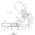
- Fig. 1 is a partially cutaway view schematically showing a pretensioner used in an embodiment of a seat belt apparatus according to the present invention.
- a pretensioner 1 used in a seat belt apparatus of this embodiment is a buckle pretensioner comprising a cover (corresponding to a peripheral member of a pull-in member of the present invention) 3 which can expand and contract in the axial direction.
- One end of the cover 3 is attached to a bracket 2 and the other end of the cover 3 is attached to a well-known buckle (corresponding to the pull-in member of the present invention) 4.
- the buckle 4 is of a conventionally known type and is provided at its upper end with a tongue insertion opening (not shown).
- the buckle 4 is provided in its lower portion (the side opposite to the upper end) with a pulley 6 onto which a wire 5 is wound.
- One end of the wire 5 is fixed to the bracket 2 by well-known fixing means 7.
- the wire 5 extends through the inside of the cover 3 and is wound on a pulley 8 which is rotatably fixed to the bracket 2.
- the wire 5 further extends to be connected to a piston 9.
- the piston 9 is housed in a cylinder 10 attached to the bracket 2 such that the piston 9 is arranged slidably and airtightly by a sealing member 11 such as an O-ring.
- the end of the cylinder 10 (the side opposite to the side mounted to the bracket 2) is formed to be a taper portion 10a of a truncated cone shape with the cylinder diameter continuously decreasing toward the end of the cylinder 10.
- the cylinder is provided with a pressure chamber 12 formed therein at the side opposite to the taper portion 10a about the piston 9.
- the pressure chamber 12 is in communication with a gas generator 13 mounted to the bracket 2.
- the gas generator 13 is actuated at the event of emergency to react reacting substance, thereby generating high-pressure reaction gas. The gas thus generated is introduced into the pressure chamber 12.
- the reaction gas introduced into the pressure chamber 12 acts on the piston 9 whereby the piston 9 moves toward the end of the cylinder 10 so as to pull the buckle 4 toward the bracket 2 via the wire 5.
- the piston 9 plastically deforms the taper portion 10a.
- the deformation of the taper portion 10a absorbs kinetic energy of the piston 9. That is, the taper portion 10a is structured as an energy absorbing portion 14.
- the seat belt apparatus 5 of this embodiment is further provided with a kinetic-energy absorbing member (corresponding to the kinetic-energy absorbing means of the present invention) 15 which is disposed in the cover 3 and is attached to the bracket 2.
- the kinetic-energy absorbing member 15 comprises an oval tubular member having thin wall.
- the tubular member is made of metal such as iron or aluminum.
- the kinetic-energy absorbing member 15 is arranged such that the axial direction thereof (the axial direction of the tubular member) is equal to the direction of pulling the buckle 4.
- the bracket-side end (the lower end in a lower illustration of Fig. 2(a)), facing the bracket 2, of the kinetic-energy absorbing member 15 is fixed to the bracket 2 and the buckle-side end (the upper end in the lower illustration of Fig. 2(a)), facing the buckle 4, of the kinetic-energy absorbing member 15 is a free end (also in Figs. 2(b) through 2(g) and Figs. 3(a) through 3(g), the bracket-side end of the kinetic-energy absorbing member 15 is the lower end of each illustration and the buckle-side end of the kinetic-energy absorbing member 15 is the upper end of each illustration).
- the wire 5 forms a U-turn about the pulley 6 of the buckle 4 so as to have two wire portions 5a, 5b which extend through the inside of the tubular kinetic-energy absorbing member 15.
- the other structures of the seat belt apparatus of this embodiment are substantially the same as those of the conventionally-known seat belt apparatus disclosed in the aforementioned Japanese Patent Unexamined Publication No. 2003-54360.
- the pretensioner 1 in the normal state, the pretensioner 1 is not actuated so that the buckle 4 is held at a predetermined position shown in Fig. 1.
- the buckle 4 In this state, the buckle 4 is spaced apart from the kinetic-energy absorbing member 15 and the kinetic-energy absorbing member 15 is in free state.
- the position of the buckle-side end of the kinetic-energy absorbing member 15 is set at the buckle side from a maximum permissible contraction position of the cover 3.
- the buckle pretensioner 1 is actuated in the same manner as the conventional seat belt apparatus.
- the gas generator 13 generates high-pressure reaction gas and the reaction gas thus generated is introduced into the pressure chamber 12.
- the reaction gas introduced into the pressure chamber act on the piston 9 so that the piston 9 rapidly moves toward to the end of the cylinder 10, thereby pulling the wire 5.
- This causes the buckle 4 to be pulled towards the bracket 2 (in the direction diagonally toward the right below in Fig. 1) with contracting the cover 3.
- the buckle 4 Since the free end of the shock absorbing member 15 is positioned at the buckle side from the maximum permissible contraction position of the cover 3, the buckle 4 is pulled to come in contact with the buckle-side end of the kinetic-energy absorbing member 15 in tandem with the reach of the piston 9 to the taper portion 10a before the cover 3 is contracted to the maximum permissible contraction position of the cover. After that, the buckle 4 is pulled so as to depress the kinetic-energy absorbing member 15 with the bracket 2 to contract and deform (collapse) the kinetic-energy absorbing member 15. Because of the contraction and deformation of the kinetic-energy absorbing member 15, the kinetic-energy absorbing member 15 absorbs the kinetic energy of the buckle 4.
- the buckle 4 As the force of the buckle 4 pressing the kinetic-energy absorbing member 15 based on the pulling force of the buckle pretensioner 1 as shown in Fig. 1 becomes equal to the counter force of the kinetic-energy absorbing member 15, the buckle 4 is stopped to be pulled, that is, the buckle 4 reaches the bottom. Since the kinetic-energy absorbing member 15 absorbs the kinetic-energy of the buckle 4 during this, the buckle 4 softly reaches the bottom.
- the buckle softly reaches the bottom to stop because the kinetic-energy of the buckle 4 when reaching the bottom is absorbed by the kinetic-energy absorbing member 15. Since the kinetic-energy absorbing member 15 is composed of the thin-walled tubular member of simple shape made of metal such as iron or aluminum, the kinetic-energy absorbing member 15 can be easily manufactured at low cost.
- the kinetic energy of the piston 9 moving at high speed is absorbed by the energy absorbing portion 14 just before the buckle 4 reaches the bottom. Since the taper portion 10a as the kinetic-energy absorbing portion 14 is deformed by the movement of the piston 9, the absorption of kinetic energy of the buckle 4 can be achieved with a simple structure.
- the kinetic energy of the buckle 4 when reaching the bottom is absorbed by the kinetic-energy absorbing member 15, whereby the kinetic energy applied to the cover 3 influenced by the pulling operation of the buckle 4 is reduced. Since iron or aluminum is used as the metal, an existing iron pipe or aluminum pipe can be employed. In this case, the kinetic-energy absorbing member 15 can be further easily manufactured at lower cost.
- the bracket-side end of the kinetic-energy absorbing member 15 is fixed to the bracket 2 in this embodiment, the bracket-side end of the kinetic-energy absorbing member 15 may not be fixed to the bracket 2 so that the both ends of the kinetic-energy absorbing member 15 may be free ends relative to the bracket 2. That is, it is only required that the kinetic-energy absorbing member 15 is arranged between the bracket 2 and the buckle 4. It does not matter whether the end of the kinetic-energy absorbing member 15 is fixed to the bracket 2 or not. In this case, the bracket-side end may be just in contact with the bracket 2.
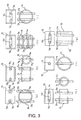
- Figs. 2(b) through 2(g) and Fig. 3(a) through 3(g) are illustrations showing different examples of the kinetic-energy absorbing member 15.
- the kinetic-energy absorbing member 15 is composed of a thin-walled rectangular tubular member.
- the kinetic-energy absorbing member 15 is composed of a thin-walled oval tubular member similar to the example of Fig. 2(a), but the tubular member of this example is provided with two V-like grooves 15a, 15b formed at an upper side and a lower side to extend in the peripheral direction for assisting in contraction and deformation of the tubular member.
- the kinetic-energy absorbing member 15 is composed of a thin-walled rectangular tubular member similar to the example of Fig. 2(b), but the tubular member of this example is provided with two V-like grooves 15a, 15b, having the same function as the V-like grooves 15a, 15b in Fig. 2(c), formed at an upper side and a lower side to extend in the peripheral direction.
- the kinetic-energy absorbing member 15 is composed of a thin-walled oval tubular member similar to the example of Fig. 2(a).
- the kinetic-energy absorbing member 15 is composed of a thin-walled rectangular tubular member similar to the example of Fig. 2(b).
- the tubular members of these examples are each provided with U-like grooves 15c, 15d, having the same function as the V-like grooves 15a, 15b in Fig. 2(c), formed at an upper side and a lower side to extend in the peripheral direction.
- the kinetic-energy absorbing member 15 is arranged such that the axial direction thereof (the axial direction of the tubular member) is equal to the direction of pulling the buckle 4 and two wire portions 5a, 5b extend through the inside of the tubular member.
- the kinetic-energy member 15 comprises a tubular member having an oval section and a thin wall similar to the example of Fig. 2(a).
- three such tubular members are stacked on each other and are bonded to each other by welding or the like.
- the three tubular members are arranged such that the axial directions thereof are perpendicular to the pulling direction of the buckle 4 and the three tubular members are stacked on each other in the pulling direction.
- the three tubular members are each provided with concaved U-like grooves 15e, 15f formed in opposing arc portions thereof so that when the three tubular members are stacked on each other, the U-like grooves 15e, 15f form guide grooves 15g, 15h through which two wire portions 5a, 5b are inserted and guided, respectively.
- the tubular member is easy to collapse and easy to absorb energy as compared to the aforementioned examples, in which the axial direction of the tubular member is equal to the pulling direction of the buckle 4.
- the kinetic-energy absorbing member 15 is composed of a thin-walled tubular member.
- the tubular member is arranged such that the axial direction thereof is perpendicular to the pulling direction of the buckle 4.
- the tubular member is provided with concaved U-like grooves 15e, 15f, formed in opposing arc portions thereof, through which two wire portions 5a, 5b are inserted and guided.
- the tubular member is easy to collapse and easy to absorb energy because the axial direction of the tubular member is perpendicular to the pulling direction of the buckle 4.
- the kinetic-energy absorbing member 15 is composed of a thin-walled tubular member having a thin-walled circular section.
- the tubular member is arranged such that the axial direction thereof is perpendicular to the pulling direction of the buckle 4.
- the tubular member is provided with U-like grooves 15e, 15f, formed in opposing ends thereof, through which two wire portions 5a, 5b are inserted and guided.
- the tubular member is easy to collapse and easy to absorb energy because the axial direction of the tubular member is perpendicular to the pulling direction of the buckle 4.
- the kinetic-energy absorbing member 15 is composed of three thin-walled oval tubular members which are stacked and bonded to each other similar to the example shown in Fig. 2(g).
- the kinetic-energy absorbing member 15 is not provided with the U-like grooves 15e, 15f shown in Fig. 2(g).
- the kinetic-energy absorbing member 15 is provided with oval guide holes 15i through which the two wire portions 5a, 5b extend.
- the guide holes 15i are formed in the peripheral surfaces of the tubular members to extend in a direction perpendicular to the pulling direction of the buckle 4.
- the tubular members are easy to collapse and easy to absorb energy similar to the example shown in Fig. 2(g).
- the kinetic-energy absorbing member 15 is composed of a thin-walled tubular member just like the example shown in Fig. 3(a). In this case, the kinetic-energy absorbing member 15 is not provided with the U-like grooves 15e, 15f shown in Fig. 3(a). Instead of these, the kinetic-energy absorbing member 15 is provided with oval guide holes 15i through which the two wire portions 5a, 5b extend. The guide holes 15i are formed in the peripheral surfaces of the tubular member to extend in a direction perpendicular to the pulling direction of the buckle 4. According to the kinetic-energy absorbing member 15 of this example, the tubular member is easy to collapse and easy to absorb energy similar to the example shown in Fig. 3(a).
- the kinetic-energy absorbing member 15 is composed of a thin-walled tubular member just like the example shown in Fig. 3(b). In this case, the kinetic-energy absorbing member 15 is not provided with the U-like grooves 15e, 15f shown in Fig. 3(b). Instead of these, the kinetic-energy absorbing member 15 is provided with oval guide holes 15i through which the two wire portions 5a, 5b extend. The guide holes 15i are formed in the peripheral surfaces of the tubular member to extend in a direction perpendicular to the pulling direction of the buckle 4. According to the kinetic-energy absorbing member 15 of this example, the tubular member is easy to collapse and easy to absorb energy similar to the example shown in Fig. 3(b).
- the kinetic-energy absorbing member 15 is composed of a thin-walled tubular member just like the example shown in Fig. 3(d).
- the kinetic-energy absorbing member 15 is provided with circular guide holes 15j through which a wire portion of the wire 5 extends.
- the wire 5 extending from a pulley 8 of the bracket 2 to the buckle 4 is directly connected to the buckle 4 without forming a U-turn at the pulley 6 of the buckle 4 like the example shown in Fig. 1. Therefore, only one wire portion 5 extends through the circular guide holes 15j.
- the tubular member is easy to collapse and easy to absorb energy similar to the example shown in Fig. 3(d).
- the kinetic-energy absorbing member 15 is composed of a thick-walled rectangular tubular member which is provided with guide hole 15i having an oval section formed therein.
- the tubular member is arranged such that the axial direction thereof is equal to the pulling direction of the buckle 4 similar to the example of Fig. 2(b).
- the kinetic-energy absorbing member 15 of any of the examples shown in Figs. 2(b) through 2(g) and Fig. 3(a) through 3(g) is made of metal such as iron or aluminum similar to the example of Fig. 2(a).
- the present invention does not necessarily require this energy portion 14 so that it may be omitted.
- the pretensioner used for the seat belt apparatus of the present invention has been described as a buckle pretensioner used in the buckle 4 in any of the aforementioned examples, the pretensioner of the seat belt apparatus of the present invention may be applied as a pretensioner used in a lap anchor.
- the pretensioner used for the seat belt apparatus of the present invention is a pretensioner which is employed for a seat belt apparatus installed in a seat of a vehicle such as automobile and which is actuated in the event of emergency such as a vehicle collision to tension a seat belt so as to provide improved occupant restraint, and is thus suitably used as a pretensioner of a type of pulling a buckle or a lap anchor, thereby tensioning the seat belt.
Landscapes
- Engineering & Computer Science (AREA)
- Mechanical Engineering (AREA)
- Automotive Seat Belt Assembly (AREA)
Abstract
Description
A further embodiment is characterized in that said metal is iron or aluminum.
Furthermore, a still further embodiment is characterized in that said pull-in member is a buckle and/or a lap anchor.
Since the kinetic-energy absorbing means of the present invention is composed of a tubular member of a simple shape made of metal, the kinetic-energy absorbing means can be easily manufactured at low cost.
If iron or aluminum is used as the metal, an existing iron pipe or aluminum pipe can be employed. In this case, the kinetic-energy absorbing member can be further easily manufactured at lower cost.
As shown in Fig. 1, a pretensioner 1 used in a seat belt apparatus of this embodiment is a buckle pretensioner comprising a cover (corresponding to a peripheral member of a pull-in member of the present invention) 3 which can expand and contract in the axial direction. One end of the cover 3 is attached to a
The
In the example shown in Fig. 2(b), the kinetic-
Though the pretensioner used for the seat belt apparatus of the present invention has been described as a buckle pretensioner used in the buckle 4 in any of the aforementioned examples, the pretensioner of the seat belt apparatus of the present invention may be applied as a pretensioner used in a lap anchor.
Claims (4)
- A seat belt apparatus comprising at least a pretensioner for pulling a pull-in member (4) to tension a seat belt in the event of emergency,
further comprising a kinetic-energy absorbing means (15) for absorbing the kinetic energy of said pull-in member (4) when reaching the bottom, wherein the kinetic-energy absorbing means (15) is composed of a tubular member made of metal. - A seat belt apparatus as claimed in claim 1, further comprising a peripheral member (3) around the kinetic-energy absorbing means (15) and influenced by the pulling operation of said pull-in member (4).
- A seat belt apparatus as claimed in claim 1 or 2, wherein said metal is iron or aluminum.
- A seat belt apparatus as claimed in any one of claims 1 through 3, wherein said pull-in member (4) is a buckle and/or lap anchor.
Applications Claiming Priority (4)
| Application Number | Priority Date | Filing Date | Title |
|---|---|---|---|
| JP2004006451 | 2004-01-14 | ||
| JP2004006451 | 2004-01-14 | ||
| JP2004276636 | 2004-09-24 | ||
| JP2004276636A JP4573295B2 (en) | 2004-01-14 | 2004-09-24 | Seat belt device |
Publications (2)
| Publication Number | Publication Date |
|---|---|
| EP1555172A1 true EP1555172A1 (en) | 2005-07-20 |
| EP1555172B1 EP1555172B1 (en) | 2007-01-03 |
Family
ID=34622258
Family Applications (1)
| Application Number | Title | Priority Date | Filing Date |
|---|---|---|---|
| EP05000497A Expired - Lifetime EP1555172B1 (en) | 2004-01-14 | 2005-01-12 | Seat belt apparatus |
Country Status (5)
| Country | Link |
|---|---|
| US (1) | US7631899B2 (en) |
| EP (1) | EP1555172B1 (en) |
| JP (1) | JP4573295B2 (en) |
| CN (1) | CN100450836C (en) |
| DE (1) | DE602005000381T2 (en) |
Cited By (1)
| Publication number | Priority date | Publication date | Assignee | Title |
|---|---|---|---|---|
| CN101659249A (en) * | 2008-08-29 | 2010-03-03 | 现代自动车株式会社 | Seat belt pretensioner |
Families Citing this family (17)
| Publication number | Priority date | Publication date | Assignee | Title |
|---|---|---|---|---|
| US20040232670A1 (en) * | 2002-03-12 | 2004-11-25 | Trw Vehicle Safety Systems Inc. | Apparatus for measuring tension in seat belt webbing |
| EP1507834A1 (en) | 2002-05-29 | 2005-02-23 | E.I. Du Pont De Nemours And Company | Fibrillar microstructure for conformal contact and adhesion |
| US7533902B2 (en) * | 2006-05-31 | 2009-05-19 | Key Safety Systems, Inc. | Seat belt pretensioner using preformed tubes |
| CN100417554C (en) * | 2006-10-02 | 2008-09-10 | 陈万松 | Automobile safety belt rotary pretensioner |
| KR100936315B1 (en) * | 2008-04-22 | 2010-01-12 | 현대자동차주식회사 | Seat belt tensioner |
| US7784831B2 (en) * | 2008-06-27 | 2010-08-31 | Gm Global Technology Operations, Inc. | Seat belt load limiting device |
| JP5473322B2 (en) | 2008-12-29 | 2014-04-16 | テイ・エス テック株式会社 | Vehicle seat |
| JP5710297B2 (en) * | 2011-02-01 | 2015-04-30 | 芦森工業株式会社 | Pretensioner device and seat belt device |
| DE102011108349A1 (en) * | 2011-07-25 | 2013-01-31 | Trw Automotive Gmbh | Tensor for a safety belt |
| DE102011112259A1 (en) * | 2011-09-02 | 2013-03-07 | GM Global Technology Operations LLC (n. d. Gesetzen des Staates Delaware) | Vehicle seat e.g. for motor vehicle, has traction mechanism that is provided for increasing inclination angle of seat surface of seat portion during vehicle accident, and safety belt that is actuated or operated by traction mechanism |
| DE102012001283B4 (en) * | 2012-01-25 | 2023-08-10 | Zf Automotive Germany Gmbh | Positioning device for a vehicle belt presenter and buckle device |
| JP2013163502A (en) * | 2012-02-13 | 2013-08-22 | Takata Corp | Pretensioner and seat belt apparatus including the same |
| KR101326489B1 (en) * | 2012-08-30 | 2013-11-08 | 현대자동차주식회사 | Anchor pre-tensioner for safety seat belt |
| JP6420474B2 (en) * | 2015-05-26 | 2018-11-07 | オートリブ ディベロップメント エービー | Seat belt device |
| JP7543613B2 (en) * | 2020-10-28 | 2024-09-03 | Joyson Safety Systems Japan合同会社 | Buckle pretensioner and seat belt device |
| KR20230043486A (en) * | 2021-09-24 | 2023-03-31 | 현대자동차주식회사 | Pre-tensioner for seat belt |
| DE102022201664B4 (en) | 2022-02-17 | 2024-09-26 | Joyson Safety Systems Germany Gmbh | Force limiter for a seat belt |
Citations (4)
| Publication number | Priority date | Publication date | Assignee | Title |
|---|---|---|---|---|
| US6095615A (en) * | 1996-03-28 | 2000-08-01 | Trw Occupant Restraint Systems Gmbh | Occupant restraint system with a belt pretensioner |
| US6131951A (en) * | 1998-05-08 | 2000-10-17 | Breed Automotive Technology, Inc. | Pretensioner |
| US6250720B1 (en) * | 1996-04-23 | 2001-06-26 | Trw Occupant Restraint Systems Gmbh & Co. Kg | Tensioner for a safety belt |
| EP1266808A1 (en) * | 2001-06-06 | 2002-12-18 | Takata Corporation | Seatbelt device |
Family Cites Families (18)
| Publication number | Priority date | Publication date | Assignee | Title |
|---|---|---|---|---|
| JPH0562363A (en) | 1991-08-30 | 1993-03-12 | Victor Co Of Japan Ltd | Recording and reproducing method |
| DE4307062A1 (en) * | 1993-03-06 | 1994-09-08 | Trw Repa Gmbh | Belt tensioners for seat belt systems in vehicles |
| DE9303276U1 (en) * | 1993-03-06 | 1993-04-22 | TRW Repa GmbH, 7077 Alfdorf | Belt tensioners in a safety belt system for vehicles |
| JP3308348B2 (en) | 1993-06-10 | 2002-07-29 | タカタ株式会社 | Pretensioner for seat belt device |
| JPH07223503A (en) | 1993-12-15 | 1995-08-22 | Tokai Rika Co Ltd | Bag body for air bag device |
| JPH07251707A (en) | 1994-03-16 | 1995-10-03 | Nippondenso Co Ltd | Seat belt tightening device |
| JPH08324384A (en) | 1995-06-02 | 1996-12-10 | Nippondenso Co Ltd | Seat belt tightening device |
| JP2963883B2 (en) * | 1996-04-23 | 1999-10-18 | ティーアールダブリュ オキュパント リストレイント システムズ ゲゼルシャフト ミット ベシュレンクテル ハフツング | Vehicle seat with integrated belt tensioner |
| USH1833H (en) * | 1996-12-18 | 2000-02-01 | The United States Of America As Represented By The Secretary Of The Army | Apparatus for absorbing mine blast energy |
| DE29707352U1 (en) * | 1997-04-23 | 1997-08-21 | Trw Occupant Restraint Systems Gmbh, 73551 Alfdorf | Tightener for a seat belt |
| US5944350A (en) * | 1997-11-14 | 1999-08-31 | Takata Inc. | Buckle pretensioner |
| DE29800909U1 (en) * | 1998-01-20 | 1998-05-20 | Trw Occupant Restraint Systems Gmbh, 73551 Alfdorf | Assembly of a belt buckle, a mounting bracket and a force limiter |
| JP2002308045A (en) * | 2001-04-12 | 2002-10-23 | Takata Corp | Seat belt device |
| JP4448626B2 (en) * | 2001-07-18 | 2010-04-14 | 本田技研工業株式会社 | Crew protection device |
| US6851715B2 (en) * | 2002-03-12 | 2005-02-08 | Trw Vehicle Safety Systems Inc. | Apparatus for measuring tension in seat belt webbing |
| DE10215539B4 (en) * | 2002-04-09 | 2005-07-21 | Key Safety Systems, Inc., Sterling Heights | Belt retractor for a vehicle seat belt |
| JP2004090667A (en) * | 2002-08-29 | 2004-03-25 | Takata Corp | Seat belt device |
| US7118132B2 (en) * | 2003-04-22 | 2006-10-10 | Honda Motor Co., Ltd. | Cover structure of seat belt pretensioner |
-
2004
- 2004-09-24 JP JP2004276636A patent/JP4573295B2/en not_active Expired - Fee Related
-
2005
- 2005-01-12 DE DE602005000381T patent/DE602005000381T2/en not_active Expired - Lifetime
- 2005-01-12 EP EP05000497A patent/EP1555172B1/en not_active Expired - Lifetime
- 2005-01-13 CN CNB2005100044443A patent/CN100450836C/en not_active Expired - Fee Related
- 2005-01-14 US US11/034,889 patent/US7631899B2/en not_active Expired - Fee Related
Patent Citations (4)
| Publication number | Priority date | Publication date | Assignee | Title |
|---|---|---|---|---|
| US6095615A (en) * | 1996-03-28 | 2000-08-01 | Trw Occupant Restraint Systems Gmbh | Occupant restraint system with a belt pretensioner |
| US6250720B1 (en) * | 1996-04-23 | 2001-06-26 | Trw Occupant Restraint Systems Gmbh & Co. Kg | Tensioner for a safety belt |
| US6131951A (en) * | 1998-05-08 | 2000-10-17 | Breed Automotive Technology, Inc. | Pretensioner |
| EP1266808A1 (en) * | 2001-06-06 | 2002-12-18 | Takata Corporation | Seatbelt device |
Cited By (2)
| Publication number | Priority date | Publication date | Assignee | Title |
|---|---|---|---|---|
| CN101659249A (en) * | 2008-08-29 | 2010-03-03 | 现代自动车株式会社 | Seat belt pretensioner |
| CN101659249B (en) * | 2008-08-29 | 2013-06-05 | 现代自动车株式会社 | Seat belt pretensioner |
Also Published As
| Publication number | Publication date |
|---|---|
| US20050151365A1 (en) | 2005-07-14 |
| JP4573295B2 (en) | 2010-11-04 |
| DE602005000381D1 (en) | 2007-02-15 |
| CN1640732A (en) | 2005-07-20 |
| JP2005225476A (en) | 2005-08-25 |
| US7631899B2 (en) | 2009-12-15 |
| DE602005000381T2 (en) | 2007-11-08 |
| EP1555172B1 (en) | 2007-01-03 |
| CN100450836C (en) | 2009-01-14 |
Similar Documents
| Publication | Publication Date | Title |
|---|---|---|
| EP1555172B1 (en) | Seat belt apparatus | |
| US4258934A (en) | Seat belt tensioning device | |
| JP5054105B2 (en) | Pretensioner and manufacturing method thereof | |
| EP1557328B1 (en) | Pretensioner | |
| US6131951A (en) | Pretensioner | |
| EP2246223B1 (en) | Pretensioner, seat belt retractor having the same, and seat belt apparatus provided therewith | |
| KR100374620B1 (en) | Shoulder anchor structure | |
| CN101492038B (en) | Pretensioner and seat belt apparatus | |
| EP1266808B1 (en) | Seatbelt device | |
| RU2699167C1 (en) | Device of three-point safety belt | |
| CN110139782B (en) | Safety belt device for a vehicle | |
| US7168742B2 (en) | Seatbelt device | |
| US20050218647A1 (en) | Pre-tensioner | |
| KR102890443B1 (en) | Towbar pretensioner assembly | |
| JP3822875B2 (en) | Pretensioner gas generator mounting structure and mounting method | |
| KR20230061457A (en) | belt retractor | |
| JP4187872B2 (en) | Seat belt device | |
| JP5108643B2 (en) | Preloader | |
| WO2016190046A1 (en) | Seat belt device | |
| GB2351476A (en) | Gas generator having an electromagnetic attenuator | |
| KR200163126Y1 (en) | Retractor for seat belt | |
| JP7324149B2 (en) | Pretensioner and seat belt device | |
| JP2025084272A (en) | Energy absorbing device and seat belt device | |
| JPH09109831A (en) | Seat belt retractor |
Legal Events
| Date | Code | Title | Description |
|---|---|---|---|
| PUAI | Public reference made under article 153(3) epc to a published international application that has entered the european phase |
Free format text: ORIGINAL CODE: 0009012 |
|
| AK | Designated contracting states |
Kind code of ref document: A1 Designated state(s): AT BE BG CH CY CZ DE DK EE ES FI FR GB GR HU IE IS IT LI LT LU MC NL PL PT RO SE SI SK TR |
|
| AX | Request for extension of the european patent |
Extension state: AL BA HR LV MK YU |
|
| 17P | Request for examination filed |
Effective date: 20051206 |
|
| AKX | Designation fees paid |
Designated state(s): DE FR GB SE |
|
| GRAP | Despatch of communication of intention to grant a patent |
Free format text: ORIGINAL CODE: EPIDOSNIGR1 |
|
| GRAS | Grant fee paid |
Free format text: ORIGINAL CODE: EPIDOSNIGR3 |
|
| GRAA | (expected) grant |
Free format text: ORIGINAL CODE: 0009210 |
|
| AK | Designated contracting states |
Kind code of ref document: B1 Designated state(s): DE FR GB SE |
|
| REG | Reference to a national code |
Ref country code: GB Ref legal event code: FG4D |
|
| REF | Corresponds to: |
Ref document number: 602005000381 Country of ref document: DE Date of ref document: 20070215 Kind code of ref document: P |
|
| REG | Reference to a national code |
Ref country code: SE Ref legal event code: TRGR |
|
| ET | Fr: translation filed | ||
| PLBE | No opposition filed within time limit |
Free format text: ORIGINAL CODE: 0009261 |
|
| STAA | Information on the status of an ep patent application or granted ep patent |
Free format text: STATUS: NO OPPOSITION FILED WITHIN TIME LIMIT |
|
| 26N | No opposition filed |
Effective date: 20071005 |
|
| PGFP | Annual fee paid to national office [announced via postgrant information from national office to epo] |
Ref country code: SE Payment date: 20080104 Year of fee payment: 4 |
|
| PGFP | Annual fee paid to national office [announced via postgrant information from national office to epo] |
Ref country code: FR Payment date: 20080108 Year of fee payment: 4 |
|
| EUG | Se: european patent has lapsed | ||
| REG | Reference to a national code |
Ref country code: FR Ref legal event code: ST Effective date: 20091030 |
|
| PG25 | Lapsed in a contracting state [announced via postgrant information from national office to epo] |
Ref country code: FR Free format text: LAPSE BECAUSE OF NON-PAYMENT OF DUE FEES Effective date: 20090202 |
|
| PG25 | Lapsed in a contracting state [announced via postgrant information from national office to epo] |
Ref country code: SE Free format text: LAPSE BECAUSE OF NON-PAYMENT OF DUE FEES Effective date: 20090113 |
|
| PGFP | Annual fee paid to national office [announced via postgrant information from national office to epo] |
Ref country code: GB Payment date: 20130109 Year of fee payment: 9 |
|
| GBPC | Gb: european patent ceased through non-payment of renewal fee |
Effective date: 20140112 |
|
| PG25 | Lapsed in a contracting state [announced via postgrant information from national office to epo] |
Ref country code: GB Free format text: LAPSE BECAUSE OF NON-PAYMENT OF DUE FEES Effective date: 20140112 |
|
| REG | Reference to a national code |
Ref country code: DE Ref legal event code: R082 Ref document number: 602005000381 Country of ref document: DE Representative=s name: KRAUS & WEISERT PATENTANWAELTE PARTGMBB, DE Ref country code: DE Ref legal event code: R081 Ref document number: 602005000381 Country of ref document: DE Owner name: JOYSON SAFETY SYSTEMS JAPAN K.K., JP Free format text: FORMER OWNER: TAKATA CORP., TOKIO/TOKYO, JP |
|
| PGFP | Annual fee paid to national office [announced via postgrant information from national office to epo] |
Ref country code: DE Payment date: 20190123 Year of fee payment: 15 |
|
| REG | Reference to a national code |
Ref country code: DE Ref legal event code: R119 Ref document number: 602005000381 Country of ref document: DE |
|
| PG25 | Lapsed in a contracting state [announced via postgrant information from national office to epo] |
Ref country code: DE Free format text: LAPSE BECAUSE OF NON-PAYMENT OF DUE FEES Effective date: 20200801 |