EP1553768A2 - Information recording medium, information recording method, information playback method, information recording apparatus, and information playback apparatus - Google Patents
Information recording medium, information recording method, information playback method, information recording apparatus, and information playback apparatus Download PDFInfo
- Publication number
- EP1553768A2 EP1553768A2 EP05100037A EP05100037A EP1553768A2 EP 1553768 A2 EP1553768 A2 EP 1553768A2 EP 05100037 A EP05100037 A EP 05100037A EP 05100037 A EP05100037 A EP 05100037A EP 1553768 A2 EP1553768 A2 EP 1553768A2
- Authority
- EP
- European Patent Office
- Prior art keywords
- information
- recording
- data
- sob
- playback
- Prior art date
- Legal status (The legal status is an assumption and is not a legal conclusion. Google has not performed a legal analysis and makes no representation as to the accuracy of the status listed.)
- Withdrawn
Links
Images






















Classifications
-
- H—ELECTRICITY
- H04—ELECTRIC COMMUNICATION TECHNIQUE
- H04N—PICTORIAL COMMUNICATION, e.g. TELEVISION
- H04N9/00—Details of colour television systems
- H04N9/79—Processing of colour television signals in connection with recording
- H04N9/80—Transformation of the television signal for recording, e.g. modulation, frequency changing; Inverse transformation for playback
- H04N9/804—Transformation of the television signal for recording, e.g. modulation, frequency changing; Inverse transformation for playback involving pulse code modulation of the colour picture signal components
- H04N9/8042—Transformation of the television signal for recording, e.g. modulation, frequency changing; Inverse transformation for playback involving pulse code modulation of the colour picture signal components involving data reduction
-
- B—PERFORMING OPERATIONS; TRANSPORTING
- B01—PHYSICAL OR CHEMICAL PROCESSES OR APPARATUS IN GENERAL
- B01D—SEPARATION
- B01D46/00—Filters or filtering processes specially modified for separating dispersed particles from gases or vapours
- B01D46/42—Auxiliary equipment or operation thereof
- B01D46/44—Auxiliary equipment or operation thereof controlling filtration
-
- A—HUMAN NECESSITIES
- A61—MEDICAL OR VETERINARY SCIENCE; HYGIENE
- A61L—METHODS OR APPARATUS FOR STERILISING MATERIALS OR OBJECTS IN GENERAL; DISINFECTION, STERILISATION OR DEODORISATION OF AIR; CHEMICAL ASPECTS OF BANDAGES, DRESSINGS, ABSORBENT PADS OR SURGICAL ARTICLES; MATERIALS FOR BANDAGES, DRESSINGS, ABSORBENT PADS OR SURGICAL ARTICLES
- A61L9/00—Disinfection, sterilisation or deodorisation of air
- A61L9/16—Disinfection, sterilisation or deodorisation of air using physical phenomena
- A61L9/22—Ionisation
-
- B—PERFORMING OPERATIONS; TRANSPORTING
- B01—PHYSICAL OR CHEMICAL PROCESSES OR APPARATUS IN GENERAL
- B01D—SEPARATION
- B01D46/00—Filters or filtering processes specially modified for separating dispersed particles from gases or vapours
- B01D46/0027—Filters or filtering processes specially modified for separating dispersed particles from gases or vapours with additional separating or treating functions
- B01D46/0038—Filters or filtering processes specially modified for separating dispersed particles from gases or vapours with additional separating or treating functions with means for influencing the odor, e.g. deodorizing substances
-
- B—PERFORMING OPERATIONS; TRANSPORTING
- B01—PHYSICAL OR CHEMICAL PROCESSES OR APPARATUS IN GENERAL
- B01D—SEPARATION
- B01D46/00—Filters or filtering processes specially modified for separating dispersed particles from gases or vapours
- B01D46/42—Auxiliary equipment or operation thereof
- B01D46/4245—Means for power supply or devices using electrical power in filters or filter elements
-
- G—PHYSICS
- G11—INFORMATION STORAGE
- G11B—INFORMATION STORAGE BASED ON RELATIVE MOVEMENT BETWEEN RECORD CARRIER AND TRANSDUCER
- G11B27/00—Editing; Indexing; Addressing; Timing or synchronising; Monitoring; Measuring tape travel
- G11B27/02—Editing, e.g. varying the order of information signals recorded on, or reproduced from, record carriers
- G11B27/031—Electronic editing of digitised analogue information signals, e.g. audio or video signals
- G11B27/034—Electronic editing of digitised analogue information signals, e.g. audio or video signals on discs
-
- G—PHYSICS
- G11—INFORMATION STORAGE
- G11B—INFORMATION STORAGE BASED ON RELATIVE MOVEMENT BETWEEN RECORD CARRIER AND TRANSDUCER
- G11B27/00—Editing; Indexing; Addressing; Timing or synchronising; Monitoring; Measuring tape travel
- G11B27/10—Indexing; Addressing; Timing or synchronising; Measuring tape travel
- G11B27/102—Programmed access in sequence to addressed parts of tracks of operating record carriers
- G11B27/105—Programmed access in sequence to addressed parts of tracks of operating record carriers of operating discs
-
- G—PHYSICS
- G11—INFORMATION STORAGE
- G11B—INFORMATION STORAGE BASED ON RELATIVE MOVEMENT BETWEEN RECORD CARRIER AND TRANSDUCER
- G11B27/00—Editing; Indexing; Addressing; Timing or synchronising; Monitoring; Measuring tape travel
- G11B27/10—Indexing; Addressing; Timing or synchronising; Measuring tape travel
- G11B27/19—Indexing; Addressing; Timing or synchronising; Measuring tape travel by using information detectable on the record carrier
- G11B27/28—Indexing; Addressing; Timing or synchronising; Measuring tape travel by using information detectable on the record carrier by using information signals recorded by the same method as the main recording
- G11B27/30—Indexing; Addressing; Timing or synchronising; Measuring tape travel by using information detectable on the record carrier by using information signals recorded by the same method as the main recording on the same track as the main recording
- G11B27/3027—Indexing; Addressing; Timing or synchronising; Measuring tape travel by using information detectable on the record carrier by using information signals recorded by the same method as the main recording on the same track as the main recording used signal is digitally coded
-
- G—PHYSICS
- G11—INFORMATION STORAGE
- G11B—INFORMATION STORAGE BASED ON RELATIVE MOVEMENT BETWEEN RECORD CARRIER AND TRANSDUCER
- G11B27/00—Editing; Indexing; Addressing; Timing or synchronising; Monitoring; Measuring tape travel
- G11B27/10—Indexing; Addressing; Timing or synchronising; Measuring tape travel
- G11B27/19—Indexing; Addressing; Timing or synchronising; Measuring tape travel by using information detectable on the record carrier
- G11B27/28—Indexing; Addressing; Timing or synchronising; Measuring tape travel by using information detectable on the record carrier by using information signals recorded by the same method as the main recording
- G11B27/32—Indexing; Addressing; Timing or synchronising; Measuring tape travel by using information detectable on the record carrier by using information signals recorded by the same method as the main recording on separate auxiliary tracks of the same or an auxiliary record carrier
- G11B27/327—Table of contents
- G11B27/329—Table of contents on a disc [VTOC]
-
- G—PHYSICS
- G11—INFORMATION STORAGE
- G11B—INFORMATION STORAGE BASED ON RELATIVE MOVEMENT BETWEEN RECORD CARRIER AND TRANSDUCER
- G11B27/00—Editing; Indexing; Addressing; Timing or synchronising; Monitoring; Measuring tape travel
- G11B27/10—Indexing; Addressing; Timing or synchronising; Measuring tape travel
- G11B27/34—Indicating arrangements
-
- G—PHYSICS
- G11—INFORMATION STORAGE
- G11B—INFORMATION STORAGE BASED ON RELATIVE MOVEMENT BETWEEN RECORD CARRIER AND TRANSDUCER
- G11B27/00—Editing; Indexing; Addressing; Timing or synchronising; Monitoring; Measuring tape travel
- G11B27/36—Monitoring, i.e. supervising the progress of recording or reproducing
-
- G—PHYSICS
- G11—INFORMATION STORAGE
- G11B—INFORMATION STORAGE BASED ON RELATIVE MOVEMENT BETWEEN RECORD CARRIER AND TRANSDUCER
- G11B20/00—Signal processing not specific to the method of recording or reproducing; Circuits therefor
- G11B20/00086—Circuits for prevention of unauthorised reproduction or copying, e.g. piracy
- G11B20/00731—Circuits for prevention of unauthorised reproduction or copying, e.g. piracy involving a digital rights management system for enforcing a usage restriction
- G11B20/00746—Circuits for prevention of unauthorised reproduction or copying, e.g. piracy involving a digital rights management system for enforcing a usage restriction wherein the usage restriction can be expressed as a specific number
- G11B20/00753—Circuits for prevention of unauthorised reproduction or copying, e.g. piracy involving a digital rights management system for enforcing a usage restriction wherein the usage restriction can be expressed as a specific number wherein the usage restriction limits the number of copies that can be made, e.g. CGMS, SCMS, or CCI flags
-
- G—PHYSICS
- G11—INFORMATION STORAGE
- G11B—INFORMATION STORAGE BASED ON RELATIVE MOVEMENT BETWEEN RECORD CARRIER AND TRANSDUCER
- G11B20/00—Signal processing not specific to the method of recording or reproducing; Circuits therefor
- G11B20/00086—Circuits for prevention of unauthorised reproduction or copying, e.g. piracy
- G11B20/00731—Circuits for prevention of unauthorised reproduction or copying, e.g. piracy involving a digital rights management system for enforcing a usage restriction
- G11B20/00746—Circuits for prevention of unauthorised reproduction or copying, e.g. piracy involving a digital rights management system for enforcing a usage restriction wherein the usage restriction can be expressed as a specific number
- G11B20/00753—Circuits for prevention of unauthorised reproduction or copying, e.g. piracy involving a digital rights management system for enforcing a usage restriction wherein the usage restriction can be expressed as a specific number wherein the usage restriction limits the number of copies that can be made, e.g. CGMS, SCMS, or CCI flags
- G11B20/00768—Circuits for prevention of unauthorised reproduction or copying, e.g. piracy involving a digital rights management system for enforcing a usage restriction wherein the usage restriction can be expressed as a specific number wherein the usage restriction limits the number of copies that can be made, e.g. CGMS, SCMS, or CCI flags wherein copy control information is used, e.g. for indicating whether a content may be copied freely, no more, once, or never, by setting CGMS, SCMS, or CCI flags
-
- G—PHYSICS
- G11—INFORMATION STORAGE
- G11B—INFORMATION STORAGE BASED ON RELATIVE MOVEMENT BETWEEN RECORD CARRIER AND TRANSDUCER
- G11B2220/00—Record carriers by type
- G11B2220/20—Disc-shaped record carriers
- G11B2220/21—Disc-shaped record carriers characterised in that the disc is of read-only, rewritable, or recordable type
- G11B2220/215—Recordable discs
- G11B2220/216—Rewritable discs
-
- G—PHYSICS
- G11—INFORMATION STORAGE
- G11B—INFORMATION STORAGE BASED ON RELATIVE MOVEMENT BETWEEN RECORD CARRIER AND TRANSDUCER
- G11B2220/00—Record carriers by type
- G11B2220/20—Disc-shaped record carriers
- G11B2220/21—Disc-shaped record carriers characterised in that the disc is of read-only, rewritable, or recordable type
- G11B2220/215—Recordable discs
- G11B2220/218—Write-once discs
-
- G—PHYSICS
- G11—INFORMATION STORAGE
- G11B—INFORMATION STORAGE BASED ON RELATIVE MOVEMENT BETWEEN RECORD CARRIER AND TRANSDUCER
- G11B2220/00—Record carriers by type
- G11B2220/20—Disc-shaped record carriers
- G11B2220/25—Disc-shaped record carriers characterised in that the disc is based on a specific recording technology
- G11B2220/2508—Magnetic discs
- G11B2220/2516—Hard disks
-
- G—PHYSICS
- G11—INFORMATION STORAGE
- G11B—INFORMATION STORAGE BASED ON RELATIVE MOVEMENT BETWEEN RECORD CARRIER AND TRANSDUCER
- G11B2220/00—Record carriers by type
- G11B2220/20—Disc-shaped record carriers
- G11B2220/25—Disc-shaped record carriers characterised in that the disc is based on a specific recording technology
- G11B2220/2537—Optical discs
- G11B2220/2562—DVDs [digital versatile discs]; Digital video discs; MMCDs; HDCDs
-
- G—PHYSICS
- G11—INFORMATION STORAGE
- G11B—INFORMATION STORAGE BASED ON RELATIVE MOVEMENT BETWEEN RECORD CARRIER AND TRANSDUCER
- G11B2220/00—Record carriers by type
- G11B2220/20—Disc-shaped record carriers
- G11B2220/25—Disc-shaped record carriers characterised in that the disc is based on a specific recording technology
- G11B2220/2537—Optical discs
- G11B2220/2562—DVDs [digital versatile discs]; Digital video discs; MMCDs; HDCDs
- G11B2220/2575—DVD-RAMs
-
- G—PHYSICS
- G11—INFORMATION STORAGE
- G11B—INFORMATION STORAGE BASED ON RELATIVE MOVEMENT BETWEEN RECORD CARRIER AND TRANSDUCER
- G11B2220/00—Record carriers by type
- G11B2220/20—Disc-shaped record carriers
- G11B2220/25—Disc-shaped record carriers characterised in that the disc is based on a specific recording technology
- G11B2220/2537—Optical discs
- G11B2220/2579—HD-DVDs [high definition DVDs]; AODs [advanced optical discs]
-
- G—PHYSICS
- G11—INFORMATION STORAGE
- G11B—INFORMATION STORAGE BASED ON RELATIVE MOVEMENT BETWEEN RECORD CARRIER AND TRANSDUCER
- G11B2220/00—Record carriers by type
- G11B2220/40—Combinations of multiple record carriers
- G11B2220/45—Hierarchical combination of record carriers, e.g. HDD for fast access, optical discs for long term storage or tapes for backup
- G11B2220/455—Hierarchical combination of record carriers, e.g. HDD for fast access, optical discs for long term storage or tapes for backup said record carriers being in one device and being used as primary and secondary/backup media, e.g. HDD-DVD combo device, or as source and target media, e.g. PC and portable player
-
- H—ELECTRICITY
- H04—ELECTRIC COMMUNICATION TECHNIQUE
- H04N—PICTORIAL COMMUNICATION, e.g. TELEVISION
- H04N5/00—Details of television systems
- H04N5/76—Television signal recording
- H04N5/765—Interface circuits between an apparatus for recording and another apparatus
- H04N5/775—Interface circuits between an apparatus for recording and another apparatus between a recording apparatus and a television receiver
-
- H—ELECTRICITY
- H04—ELECTRIC COMMUNICATION TECHNIQUE
- H04N—PICTORIAL COMMUNICATION, e.g. TELEVISION
- H04N5/00—Details of television systems
- H04N5/76—Television signal recording
- H04N5/78—Television signal recording using magnetic recording
- H04N5/781—Television signal recording using magnetic recording on disks or drums
-
- H—ELECTRICITY
- H04—ELECTRIC COMMUNICATION TECHNIQUE
- H04N—PICTORIAL COMMUNICATION, e.g. TELEVISION
- H04N5/00—Details of television systems
- H04N5/76—Television signal recording
- H04N5/84—Television signal recording using optical recording
- H04N5/85—Television signal recording using optical recording on discs or drums
-
- H—ELECTRICITY
- H04—ELECTRIC COMMUNICATION TECHNIQUE
- H04N—PICTORIAL COMMUNICATION, e.g. TELEVISION
- H04N9/00—Details of colour television systems
- H04N9/79—Processing of colour television signals in connection with recording
- H04N9/7921—Processing of colour television signals in connection with recording for more than one processing mode
-
- H—ELECTRICITY
- H04—ELECTRIC COMMUNICATION TECHNIQUE
- H04N—PICTORIAL COMMUNICATION, e.g. TELEVISION
- H04N9/00—Details of colour television systems
- H04N9/79—Processing of colour television signals in connection with recording
- H04N9/80—Transformation of the television signal for recording, e.g. modulation, frequency changing; Inverse transformation for playback
- H04N9/82—Transformation of the television signal for recording, e.g. modulation, frequency changing; Inverse transformation for playback the individual colour picture signal components being recorded simultaneously only
- H04N9/8205—Transformation of the television signal for recording, e.g. modulation, frequency changing; Inverse transformation for playback the individual colour picture signal components being recorded simultaneously only involving the multiplexing of an additional signal and the colour video signal
Definitions
- the present invention relates to an information recording medium (or a data structure); an information recording/playback method; and an information recording/playback apparatus suitable for recording/playing back a digital stream signal for use in digital TV broadcasting or the like.
- An example of a streamer utilizing an optical disk such as a DVD-RAM includes a "recording and playback apparatus" as disclosed in Japanese Patent Application KOKAI Publication No. 6-225239 (Page 2, FIG. 1).
- an information recording medium for recording a digital stream signal comprises:
- a method for recording a digital stream signal in an information recording medium comprising a management region and a data region, the method comprises:
- a method for reproducing information from an information recording medium for recording a digital stream signal comprising:
- an apparatus for recording a digital stream signal in an information recording medium comprising a management region and a data region, the apparatus comprises:
- an apparatus for reproducing information from an information recording medium for recording a digital stream signal comprising:
- a disk-shaped information recording medium 100 includes a recordable optical disk such as a DVD-RAM using blue laser, a present DVD-RAM, a present DVD-RW, or a present DVD-R; and a recordable magnetic disk such as hard disk.
- a recordable optical disk such as a DVD-RAM using blue laser, a present DVD-RAM, a present DVD-RW, or a present DVD-R
- a recordable magnetic disk such as hard disk.
- FIGS. 1A to 1I are diagrams showing constitutions of an information recording medium, an information recording method, and an information reproducing method according to a first embodiment of the present invention.
- FIGS. 1A to 1I are explanatory views of a data structure according to one embodiment of the present invention.
- Examples of a disc-shaped information storage medium 100 include recordable optical disks such as DVD-RAM, DVD-RW, and DVD-R, and recordable magnetic disks such as a hard disk and the like.
- the optical disk 100 has a lead-in area 110, a volume/file structure information area 111, a data area 112, and a lead-out area 113 from an inner peripheral side toward an outer peripheral side thereof (FIG. 1B).
- a file system is stored in the volume/file structure information area 111.
- the file system comprises information indicating a file and a place where the file is recorded. Recorded contents are stored in the data area 112 (FIG. 1C).
- the data area 112 is divided into a general computer information recording area 120 and an AV data recording area 121.
- the AV data recording area 121 comprises an AV data management information recording area 130 in which a file (VMG/ESMG file) for controlling AV data is recorded, a VR object group recording area 122 in which an object data (VOBS) file (VRO file) of video recording specifications is recorded, and a stream object group recording area 131 in which a stream object set (SOBS) corresponding to the digital broadcasting is recorded (FIG. 1D). That is, in the embodiment, stream objects of the digital broadcasting are recorded as the stream object set SOBS which is a file separate from a VR object (FIG. 1E).
- the SOBS comprises one or more stream objects (SOBs) 132.
- Each stream object (SOB) 132 comprises a set of one or more stream object units (SOBUs) 134 which are data units constituting access units to the disk 100.
- Each stream object unit (SOBU) 134 comprises a set of one or more packet groups (Packet_Groups) 140 comprising a set of a plurality of TS packets (FIG. 1G).
- Packet_Groups packet groups
- each packet group 140 comprises a set of sixteen packs (or logical blocks: LBs).
- LB logical blocks
- a size of each packet group 140 is 32 Kbytes, and the size of the group is the same as that of ECC block defined by the DVD specifications.
- Each packet group 140 constitutes a packet recording area (DVD-TS packet recording area) 160 in stream recording (SR) provided by the present embodiment (FIG. 1H).
- the DVD-TS packet recording area 160 can comprise a packet group header 161, a plurality of (e.g., 170) MPEG-TS packets 162, and a plurality of (e.g., 170 pieces of) packet arrival time information (PAT) 163 (FIG. 1I).
- PAT packet arrival time information
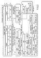
- FIG. 2 is an explanatory view of a relation among a presentation control information layer 10, a stream object control information layer 20, and a stream object layer 30 in a data structure according to one embodiment of the present invention.
- the management information (VMG file) recorded on the AV data management information recording area 130 of FIG. 1D has the presentation control information layer 10 to manage playback procedures of both recording contents based on video recording specifications and stream recording contents based on the present embodiment.
- one or more cells 13 which are playback units of a stream-recorded object constitute a program 12 together
- one or more cells 13 which are playback units of a video-recorded object constitute a program 12 together
- arrangement (playback procedure) of these programs 12 is managed by management information (PGCI) of a program chain (PGC) 11.
- PGCI management information
- PPC program chain
- a user can designate a playback place by a playback time (PTS).
- PTS playback time
- the stream object (SOB) 132 in the stream object layer 30 is designated via stream object information (SOBI) 21 in the stream object control information layer 20.
- the stream object unit (SOBU) 134 in the stream object layer 30 is designated via stream object unit entry information (SOBUI) 22 in the stream object control information layer 20.
- SOBUI stream object unit entry information
- the playback start place is specified.
- the stream object unit information (SOBUI) 22 may be referred to as global information 22.
- the stream object unit (SOBU) 32 comprises one or more packet groups 33.
- the stream object unit (SOBU) 32 corresponds to, for example, one or two GOPs, or is a unit from a head of an i-th I picture to a head of an (i+n)-th I picture (n is an integer). Additionally, when a breakpoint of the GOP is not found, the stream object unit (SOBU) 32 is divided by a unit corresponding to a data amount for one second (playback time) at maximum. Accordingly, overflow of each information field is prevented.
- Each packet group 33 comprises 16 LBs (32,768 bytes), the head thereof has a packet group header 34, and thereafter a plurality of (in this example, 170) transport stream packets (TS_Packets) 36, and a plurality of pieces of (in this example, 170) packet arrival time information (PATs) 34.
- TS_Packets transport stream packets
- PATs packet arrival time information
- a video object (VOB) 38 in a video object layer 37 is designated via video object information (VOBI) 24 in a video object (VOB) management information layer 23.
- a video object unit (VOBU) 39 in the video object layer 37 is designated via video object unit information (VOBUI) 25 in the video object management information layer 23.
- VOBUI video object unit information
- the playback start place is specified.
- the video object unit (VOBU) 39 comprises a plurality of packs 40, and the recording contents of the video recording are stored in these packs.
- a playback start place can be specified at a time interval based on the number of fields by SOBU_PB_TM. Further, when playback is started from the middle of the cell 13 at the video recording side, a playback start place can be specified according to VOBU_PB_TM (described later in detail with reference to FIG. 22) in time map information (TMAPI) defined in a video recording standard.
- VOBU_PB_TM described later in detail with reference to FIG. 22
- TMAPI time map information
- a structure of SOBS comprises one or more SOBs (Stream OBjects).
- This SOB corresponds to one program, for example.
- the SOB comprises one or more SOBUs (Stream Object Unit).
- This SOBU corresponds to object data for a predetermined time interval (refer to VOBU/SOBU_PB_TM_RNG (changing according to a value of VOBU/SOBU Playback Time Range) in FIG. 19/FIG. 17 described later) or one or more items of GOP data.
- SOBU is frequently delimited, and concurrently, SOBU control information increases, so that there is a danger that whole control information becomes large in amount. Therefore, it is proper that SOBU according to the embodiment of the present invention be delimited at a predetermined time interval (the lowest limit must be other than SOBU at the end of SOB, and SOBU is delimited in units of pictures) or one or more GOPs.
- the packet group 33 comprises a packet group header 34 and TS packets.36 (170 packets).
- An arrival time of each TS packet 36 can be recognized from PAT (Packet Arrival Time: 4 bytes) allocated in pair in front of each TS packet 36.
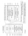
- FIG. 3 is a view illustrating a file structure according to the embodiment of the present invention.
- the data' contained in the disk 100 comprises a volume/file structure information area 111 storing a file system and a data area 112 for actually recording a data file.
- the file system stored in the volume/file structure information area 111 comprises information indicating what file is recorded and where such file is recorded, as shown in FIG. 3.
- the data area 112 is divided into a general computer information recording area 120 and an AV data recording area 121.
- the AV data recording area 121 comprises an AV data management information area 130 in which an HDVMG file (and a backup file thereof) for controlling the recorded AV data is recorded; a VR object group recording area 122 for recording an object data (VOBS) file (VRO file) in accordance with video recording specifications; and a stream object group recording area 131 for recording an object (SOBS) compatible with digital broadcasting.
- AV data management information area 130 in which an HDVMG file (and a backup file thereof) for controlling the recorded AV data is recorded
- VOBS object data
- VRO file object data
- SOBS object data compatible with digital broadcasting.
- DVD-Video (ROM Video) information are stored in a VIDEO-TS directory and DVD-RTR (recording/playback DVD) information are stored in a DVD-RTR directory, for example.
- DVD-RTR recording/playback DVD
- Information of the present DVD specifications compatible with a digital broadcasting are also recorded in a directory called DVD_HDVR, for example.
- an object of the SRO file is defined as SOBS.
- a time map file shown as Example 1 and its backup file (HR_VTMAP.BUP) are further recorded as independent files.
- These files can store information contained in the time map table TMAPT (Namely, TMAPT can be controlled as a file independent of another item of control information).
- SR (stream recording) control data is recorded in an HDVMG file common to VR (video recording), and is controlled to be common to VR.
- the SR control data and VR control data are linked with each other in units of cells, and a playback place is specified in units of playback time intervals.
- HR_THNL.DAT can be provided as a file for thumbnail (reduced image) which can be utilized for a chapter menu or the like.
- additional text file HR_TEXT.DAT other than item text (IT_TXT) or HR_EXEP. DAT for storing information added to an entry point (EP) can be provided in the DVD_HDVR directory.
- a method for adding TMAPT shown as Example 2 to the end of HDVR_VMG, as shown in FIG. 4, instead of defining TMAPT as another file, can also be used.
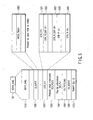
- FIG. 4 is a view illustrating an example of how a part (HDVR_VMGI), one item of the control information (HDVR_VMG) recorded in the AV data control information recording region 130, is configured.
- Stream recording in the present embodiment is abbreviated as SR (Stream Recording), and video recording is abbreviated as VR (Video Recording).
- SR data control information (STR_FIT: Stream File Information Table) is stored in the HDVR_VMG 130 (in HR_MANGER.IFO of FIG. 3), and is stored in the same manner as VR data.
- the HDVR_VMG 130 comprises: video manager information (HDVR_VMGI) 1310; a stream file information table (STR_FIT) 1320; (original) program chain information (PGCI) 1330; play list information (PL) 1340; a text data manager (TXTD_MG) 1350; a manufacturer information table (MNFIT) 1360; a_time map table TMAPT '(Example 2) 1370; and a movie AV file information table (M_AVFIT) 1380.
- the STR_FIT (Stream File Information Table) 1320 is added to control information conforming to conventional DVD-VR specifications.
- a DVD recorder has time map information (TMAPI) as VOB control information.
- TMAPI time map information
- This information is intended to enable playback, specific playback and the like in units of object data (VOB/SOB) divided into data units (VOBU/SOBU), and one item of information is required for every 0.5 seconds at a maximum.
- VOB/SOB object data
- VOBU/SOBU data units
- TMAPI time map information
- TMAPI is recorded in another region (such as HR_TMAP.IFO of FIG. 3 or TMAPT allocated at the end of HDVR_VMG of FIG. 4) in order to improve such a situation.
- the HDVR_VMGI 1310 comprises: disk management identification information (VMG_ID) 1311; a version umber of DVD video specifications (VERN) 1312; VTMAP_LAST_MOD_TM 1317 for describing an update date and time of VTMAPT; STMAP_LAST_MOD_TM 1318 for describing an update date and time of STMAPT; a start address of stream object control information (SFIT_SA) 1314; a start address of program chain information (EX_PGCI_SA) 1315; and a start address of play list information (EX_PL_SA) 1316.
- SR stream control information is stored in the STR_FIT 1320.
- each TMAP is defined as a file other than VMG, and each file can be individually modified by a personal computer or the like.
- VTMAPT update date and time information which is TMAP (Time Map) for self recording/playback of VR (video recording)
- STMAPT update date and time information which is TMAP (Time Map) for digital broadcast recording of stream recording (SR) are described, and this value and the update date and time information described in each TMAP file are compared with each other. If the values are equal to each other, processing can be performed, assuming that a coincidence is obtained.
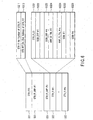
- FIG. 5 is a view illustrating an example of how other parts (M_AVFIT 1380 and STR_FIT 1320), one item (HDVR_VMG 130) of the control information, is configured in the data structure according to the embodiment of the present invention.
- VR data control information and SR stream control information are stored in the HDVR_VMG 130, whereby stream data is managed in the same manner as VR data. That is, VR data control information is stored in the M_AVFIT (Movie AV File Information Table) 1380, and the M_AVFIT 1380 includes MVOB_TMAPI (Movie Video Object Time Map Information) 13801 in VOBI (Video Object Information) for each VOB.
- M_AVFIT Morovie AV File Information Table
- stream control information is stored in the STR_FIT (Stream File Information Table) 1320, and the STR_FIT 1320 comprises STR_FITI (STR_FIT Information) 1321, one or more STR_FI_SRPs #1 to #n 1323, and one or more items of STR_FI (Stream File Information) #1 to #n 1322 indicated by its SRP.
- each STR_FI 1322 includes SOB_TMAPI having a function compatible with MVOB_TMAPI 13801 in its data hierarchy (described later with reference to FIG. 7).
- FIG. 6 is a view illustrating an example of how the STR_FITI 1321 and STR_FI 1322 of FIG. 5 are configured. That is, the STR_FITI 1321 comprises: the total number of STR_FIs 1322 (STR_FI_Ns 13211); and an end address (STR_FIT_EA 13212) of this table (STR_FIT 1320).
- the STR_FI 1322 comprises: STR_FI_GI (STR_FI General Information) 13221; one or more SOBI_SRP (Stream Object Information Search Pointer) 13222; SOBI (SOB Information) #1 to #n 13223 equal to this SOBI_SRP #1 to #n 13222 in number and indicated by that value; and one or more MNF_ID_TBL (MNF_ID: Recorder manufacturer ID: up to eight manufacturers can be recorded) 13224.
- STR_FI_GI STR_FI General Information
- SOBI_SRP Stream Object Information Search Pointer
- SOBI SOB Information #1 to #n 13223 equal to this SOBI_SRP #1 to #n 13222 in number and indicated by that value
- MNF_ID_TBL MNF_ID: Recorder manufacturer ID: up to eight manufacturers can be recorded
- FIG. 7 is a view illustrating an example of how the STR_FI_GI 13221 and SOBI 13223 of FIG. 6 are configured.
- a table used in the above NF_ID_TBL 13224 is selected (
- the PKT_TY 132214 is 01 in its contents, it is indicated that a stream included in a packet is MPEG-TS stream. If it is 0xff, it is indicated that a stream in a packet cannot be recognized or analyzed (Non-cognizant). If the PKT_SZ 132215 is 00Bch, it is indicated that a packet size is 188 bytes.
- the PKT_Ns 132217 indicates the number of packets in one packet group (for example, 0xAA: fixed to 170 TS packets).
- SOBI #1 to #k 13223 indicated by SOBI_SRP #1 to #k 13222 of corresponding number comprises: SOBI_GI (SOBI General Information) 132231; one or more SOB_ESI #1 to #m (SOB Elementary Stream Information) 132232; SOB_SMLI (SOB Seamless Information) 132233; SOB_AGAPI (SOB Audio GAP Information) 132234; SOB_TMAPI (SOB Time Map Information) 132235; and SOB_ES_GPI (SOB Elementary Stream Group Information) 132236.
- SOBI_GI SOBI General Information
- SOB_ESI #1 to #m SOB Elementary Stream Information
- SOB_SMLI SOB Seamless Information
- SOB_AGAPI SOB Audio GAP Information
- SOB_TMAPI SOB Time Map Information
- SOB_ES_GPI SOB Elementary Stream Group Information
- the SOB_ESI 132232 further comprises: SOB_V_ESI (SOB Video ESI) #1 to #m 1322321 and SOB_A_ESI (SOB Audio ESI) #1 to #m 1322322 (refer to FIG. 8).
- SOB_V_ESI SOB Video ESI
- SOB_A_ESI SOB Audio ESI
- FIG. 8 is a view illustrating an example of how the SOBI_GI 132231 included in SOBI of FIG. 7 is configured.
- the SOBI_GI further includes: SOB_TY (SOB type) 13223101; SOB_DEF_PID (SOB default PID) 13223115; SOB_REC_TM (SOB recording time) 13223112; SOB_REC_TM_SUB (SOB recording subsidiary time) 13223113; LOCAL_TM_ZONE (local time zone) 13223114; SOB_DURATION (SOB duration) 13223118; SOB_S_PTM (SOB start time) 13223116; and SOB_E_PTM (SOB end time) 13223117.
- SOB_TY SOB type
- SOB_DEF_PID SOB default PID
- FIG. 9 is a view illustrating a variety of information included in SOBI_G1 132231 of FIG. 8.
- SOB_TY 13223101 when bit B13 is 0, it is indicated to be normal SOB.
- bit b13 When bit b13 is 1, it is indicated to be SOB in a temporarily erased state.
- bit B12 When bit B12 is 0, it is indicated that GPI is not present.
- bit b12 When bit b12 is 1, it is indicated that GPI is present.
- SOB_ES_Ns 13223121; SOB_V_ES_Ns 13223122; SOB_A_ES_Ns 13223123; and ES_TMAP_Ns 13223516 have a relationship indicated by the following formula: SPB_ES_Ns ⁇ SOB_V_ES_Ns + SOB_A_ES_Ns, SOB_V_ES_Ns + SOB_A_ES_Ns ⁇ ES_TMAP_Ns
- PCR_POS_COUNT An index portion of 2 of LB indicating a position of a PCR packet is indicated by PCR_POS_SHIFT.
- a copy control is made for the purpose of copyright protection or the like by CP_CTRL_INFO.
- SOB_DEF_PID When Default PID (SOB_DEF_PID) is ARIB, it indicates a small vale of a component tag (Note that a high priority is given to a value of a component group descriptor).
- SOB_DURATION indicates SOB playback time and corresponds to a total playback time of SOBU_ENT which belongs to ES indicated by default PID.
- FIG. 8 and FIG. 9 show a case in which profile information is not provided on a disk by disk basis, and profile information is provided on a SOB by SOB basis in each disk.
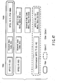
- Profile information 13223103 included in FIG. 8 will be described in detail with reference to FIG. 10 and will be described later with reference to FIG. 45.
- This information can be used to indicate support states of a variety of decode functions.
- FIG. 10 is a view illustrating a specific example of profile information of FIG. 8 and FIG. 9.
- This profile information comprises an 8-bit option support flag and a 16-bit region number. With respect to this region number, 00 indicates Japan (ARIB); 01 indicates the US (ATSC); 02 indicates Europe (DVB); and 0xffff indicates a universal code common to all countries in the world. In this manner, region data corresponding to the region number can be played back as the recorded contents.
- a format compatible function is divided into a base and a plurality of options, and options to be supported are used depending on purposes or prices.
- the above information is included in contents so that one's own support state and stream state can be compared with each other when data on options which are not supported is generated.
- the related option state (option support flag of FIG. 10) is inserted into VMGI, thereby making it possible to provide a DVD recorder compatible with a variation of plural potions (described later'in detail with reference to FIG. 45).
- FIG. 11 shows that the above settings are provided in a correlation table.
- VMGI stores information indicating what is supported by a recorder used for a disk recorded by a recorder (region code of FIG. 9) so as to indicate what is written in a disk by the supported recorder.
- streams to be decoded at the apparatus side include a number of variations which are different depending on regions. If all of these variations are supported, a configuration of a recording and playback apparatus (such as DVD recorder) becomes very huge (or complicated). As a result, apparatus cost becomes high. Therefore, in the present embodiment, contrivance is made to streams while compatibility with a number of variations is maintained, thereby making it possible to relatively lighten (simplify) device configuration.
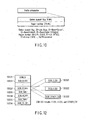
- FIG. 12 is a view illustrating an example of how SOB_ESI included in SOBI of FIG. 7 is configured.
- SOB_ESI is divided into three types (SOB_V_ESI 1322321, SOB_A_ESI 1322322, and SOB_OTHER_ESI 1322323).
- FIG. 13 is a view illustrating an example of how SOB_V_ESI included in each SOB_ESI of FIG. 12 is configured and an example of how a video attribute V_ATTR included in this SOB_V_ESI is configured.
- the SOB_V_ESI 1322321 comprises: ES_TY 13223211 indicating a format of ES; ES_PID 13223212 indicating PID of ES; STREAM_TYPE (STREAM type indicated in PMT) 13223212; COMPONENT_TAG (value of COMPONENT_TAG indicated by component descriptor) 13223214; COMPONENT_TYPE (value of COMPONENT_TYPE indicated by component descriptor) 13223216; V_ATTR 13223217 indicating a video attribute; and CP_CTL_INFO (copy control information/copyright control information) 1322318.
- V_ATTR (16 bits) 13223217 comprises an application flag for specifying a video aspect ratio and data or the like indicating a horizontal resolution.
- FIG. 14 is a view illustrating an example of how SOB_A_ESI included in each SOB_ESI of FIG. 12 is configured and an example of how an audio attribute AUDIO_ATTR included in this SOB_A_ESI is configured.
- the SOB_A_ESI 1322322 comprises: ES_TY 132232201 indicating a type of ES; ES_PID 132232202 indicating PID of ES; STREAM_TYPE (STREAM type indicated in PMT) 132232203; COMPONENT_TAG (value of COMPONENT_TAG indicated by component descriptor) 132232204; STREAM_CONTENT (value of STREAM_CONTENT indicated by component descriptor) 132232205; COMPONENT_TYPE (value of COMPONENT_TYPE indicated by component descriptor) 132232206; SIMULCAST_GP_TAG (difference value of audio frame at the time of multicast and at the start of broadcast) 132232207; AUDIO_ATTR (audio attribute value) 132232208; LANG_CODE (first audio language code) 132232209; LANG_CODE 2 (second audio language code) 132232210; and CP_CTL_INFO (copy control information/copyright control information)
- FIG. 15 is a view illustrating an example of how SOB_OTHER_ESI included in each SOB ESI of FIG. 12 is configured.
- the SOB_OTHER_ESI 1322323 comprises: ES_TY 13223231; ES_PID 13223232; STREAM_TYPE 13223233; COMPONENT_TAG 13223234; CP_CTL_INFO 13223237; and DAT_COMP_ID (data contents encoding identifier) 13223235 and AD_DAT_COMP_IFO (Additional data Component Information) 13223236.
- FIG. 16 is a view illustrating another example of how copy control information (copyright protection information) CP_CTL_INFO 13223237 included in SOB_OTHER_ESI of FIG. 15 is configured.
- CP_CTKL_INFO 13223237 is present in SOBI_GI and SOB_V_ESI; SOB_A_ESI, and CPI of Packet Group Header.
- CPI of SOBI_GI makes whole copy control
- CPI of ESI makes copy control of each ES
- copy control of each Packet Group is made by CPI of Packet Group Header.
- a higher priority is given to CPI of ESI than a CPI value of SOBI_GI, and further, the highest priority is given to CPI of Packet Group Header.
- These CPI values are set by a digital copy control descriptor and a content utilization descriptor or the like.
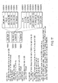
- FIG. 17 is a view illustrating an example of how SOB_TMAPI 132235 included in SOBI of FIG. 9 is configured.
- the SOB_TMAPI 132235 comprises SOB_TMAPI_GI 1322351 and one or more ES_TMAPI #1 to #n 1322352.
- each ES_TMAPI 1322352 comprises: ES_PID (PID of target ES of this TMAP) 132235211; ES_S_ADR_OFS (Packet group number from the start of SOB file to the start of this ES (or LB address) 132235214; ES_E_ADR_OFS (Packet group number from the start of SOB file to the end of this ES (or LB address) 132235217; ES_S_PTM (start PTM) 132235212; ES_E_PTM (end PTM) 132235213; ES_SOBU_ENT_Ns (the number of SOBU_ENTs) 132235216; LAST_SOBU_E_PKT_POS (position in Packet Group of the last SOBU) 132235215; STMAP_SPRN (TMAP numbers in STMAPT which belongs to this ES.
- ES_PID PID of target ES of this TMAP
- the STMAPT is recorded in another region (in another file or at the end of IFO), and comprises STMAPT 1; one or more STMAPI_SRPs; and STMAPIs whose number is equal thereto.
- the STMAP_SRP comprises STMAPI address information which is an element of each STMAPT, and each STMAPI comprises a required number of STMAPTI_GIs and SOBU_ENTs.
- the STMAPI_GI comprises SOBU_ENT_Ns (the number of ENTRYs). However, dummy data may be present between SOBU_ENTs.
- SOBU/VOBU_PB_TM_RNG is properly set, thereby making it possible to prevent TMAPI information from being extremely increased even if a recording time increases.
- FIG. 19 is a view illustrating an example of how MVOB_TMAP_GI 138011 included in MVOB_TMAP 13801 of FIG. 5 is configured.
- MVOB_TMAP_GI 138011 comprises: the number of VR movie VOBU entries MVOBU_ENT_Ns 1380111; a time offset TM_OFS 1380112; an address offset ADR_OFS 1380113; a VOBU playback time range VOBU_PB_TM_RNG (value 1 indicates 0.4 seconds to 1.2 seconds; value 2 indicates 1 second to 2 seconds, and 3 indicates 2 seconds to 3 seconds) 1380114; and a VTMAP number VTMAP_N 1380115.
- FIG. 20 is a view illustrating an example of how a time map file HR_TMAP.IFO (Example 1) included in the DVD_HDVR directory of FIG. 3 or a time map table TMAPT (Example 2) allocated at the end of HDVR_VMG of FIG. 5 is configured.
- a time map file HR_TMAP.IFO Example 1
- a time map table TMAPT Example 2 allocated at the end of HDVR_VMG of FIG. 5 is configured.
- the TMAPT is recorded in another region (in another file (FIG. 3 or the like) or at the end of IFO (FIG. 4 or the like)).
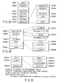
- FIG. 21 is a view illustrating an example of how a variety of information included in VTMAPT of FIG. 20 are configured.
- the VTMAPT comprises: VTMAPTI; VTMAP_SRPT; and VTMAP #1 to #n.
- the VTMAPTI comprises: VMG_ID (value equal to VMG_ID present at the start of VMGI); VTMAPT_EA (VTMAPT end address); VERN (TMAP version information); IFO_LAST_MOD_TM (TMAPT update date and time information. A value equal to HR_MANGR. IFO); and VTMAP_SRP Ns (the total number of search information).
- the VTMAP_SRPT comprises one or more VTMAP_SRPs (search information on each VTMAP).
- the VTMAP_SRP comprises: VTMAP_SA (VTMAP start address) and VOBU_ENT_Ns (the total' number of VOEU_ENTs), and the VTMAP comprises one or more VOBU_ENTs.
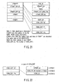
- FIG. 22 is a view illustrating an example of how the contents of VOBU_ENT of FIG. 21 are configured.
- the VOBU_ENT has the same structure as normal VR (1STREF_SZ 13703311; VOBU_PB_TM 13703312; VOBU_SZ 13703313).
- VR normal VR
- the number of bits in each field increases with an increase of recording capacity.
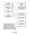
- FIG. 23 is a view illustrating an example of how a variety of information included in STMAPT of FIG. 20 are configured.
- the STMAPTI comprises: VMG_ID; STMAPT_EA (STMAP end address); VERN; STMAP_LAST_MOD_TM; and STMAP_SRP_Ns.
- the STMAP_SRP comprises: STMAP_SA (STMAP start address); ES_TMAPI_Ns (total number of ES_TMAPs); and ES_TMAPI_GI #1 to #q.
- the STMAP comprises one or more ES_TMAPs.
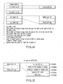
- FIG. 24 is a view illustrating an example of what kind of information is stored in ES_TMAPI_GI and ES_TMAP included in STMAP_SRP and STMAP of FIG. 23.
- the ES_TMAP_GI comprises SOBU_ENT_Ns (the total number of SOBU_ENTs) and each ES_TMAP comprises one or more SOBU_ENTs #1 to #q.
- the TMAP_SRP does not always specify TMAP in ascending order, there is no problem since individual TMAP is pointed by SRP. Dummy data may be input between TMAP fields (for example, there is no problem even if invalid data is present between TMAP #1 and TMAP #3).
- FIG. 25 is a view illustrating an example of how the contents of each SOBU_ENT of FIG. 24 are configured.
- SOBU_ENT comprises: 1st_Ref_PIC_SZ 13703301; SOBU_PB_TM (the number of fields) 13703302; SOBU_SZ (Packet GP number) 13703303; SOBU_S_PKT_POS 13703304; and PCR_POS 13703305.
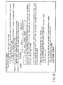
- FIG. 26 is a view illustrating of what contents SOBU has in the presence or absence of video data and audio data.
- three cases are assumed, i.e., (1) a case in which video data is available; (2) a case in which audio data is available and video data is' not available; and (3) a case in which only another item of information is available.
- Types (1), (2), and (3) are assumed. That is, in accordance with these types, SOBU entry information (SOBU_ENT) has three types as described above. The following description will be given with reference to FIG. 25.
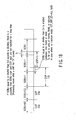
- FIG. 27 is a view showing an image of SOB in the case where a multi-view broadcast is recorded
- FIG. 28 shows a detail of FIG. 27.
- SOB_TMAPI_GI at the upper stage SOB_TMAPI_GI (refer to FIG. 17), ADR_OFS and SOB_SZ, SOB_E_PKT_POS are entered as values relating to values of the whole SOBU.
- the other stages indicate the contents of TMAPI for each ES.
- ES_TMAPI (refer to FIG.
- ES_ADR_S_OFS address (PG) from the start of SOB to the first SOBU of this ES
- ES_ADR_E_OFS address (PG) from the last SOBU of this ES to the end of SOB
- ES_LAST_SOBU_E_PKT_POS the number of packets up to the last Packet in Packet Group of the last SOBU
- SOBU_ENTN the total number of SOBU_ENTs
- default PID of this ES are entered as the value of the whole ES_TMAP.
- SOBU_ENT in each STMAPI
- ES_SOBU_S_PKT_POS and SOBU_SZ are entered as a value belonging to SOBU.
- ES_ADR_E_OFS can be obtained through calculation by the following equation (2), and thus, either of them may be present.
- SOB_SZ > ES_ADR_S_OFS, SOB_SZ > SOBU_SZ or the like is also established.
- FIG. 29 is a view illustrating an example of how SOB_ES_GPI 132236 included in SOBI of FIG. 7 is configured (GPU structural example 1).
- FIG. 30 is a view illustrating an example of how SOB_ES_GPI_GI 1322361, GPI_SRP 1322362, and GPI 1322363 included in SOB_ES_GPI 132236 of FIG. 29 are configured (GPI structure of Example 1).
- FIG. 31 is a view illustrating an example of how CPI_GI 13223631 included in GPI 1322363 of FIG. 30 is configured (GPI structure of Example 1).
- SOB a multi-view broadcast or a rainfall compatible broadcast
- SOB_ES_GPI SOB_ES Group information 1322361 compatible with simultaneous recording
- SQB_ES_GPI 132236 comprises: SOB_ES_GPI_GI 1322361; GPI_SRP #1 to #m 1322362; and GPI #1 to #m 1322363 (FIG. 29).
- GPI_SRP_Ns (the number of ES_GPI_SRPs) 13223611 is entered into the SOB_ES_GPI_GI 1322361 (FIG. 30).
- the GPI_SRP 1322362 comprises: GPI_SA (GPI start address) 13223621 and GPI_SZ (GPI size) (Alternatively, this can be substituted by PID_Ns indicating the number of PIDs, see FIG. 30).
- Each GPI 1322363 comprises: GPI_GI 13223631 and one or more ES_PIDs #1 to #n 13223632 (FIG. 30).
- Block_TY 132236311 As to which type of group this group belong to by the Block_TY 132236311; as to whether or not switching is provided by an angle button; and as to whether or not switching is performed by a rainfall compatible button (if any) (When another program is recorded at the same time, this button cannot be freely switched).
- BLOCK_NUMBER Block number
- one ES belongs to a plurality of GPs, for example, when an angle is switched by pressing a multi-angle key, and further, an image is distorted due to a rainfall and when a rainfall GP is switched by the rainfall button, the same ES is recorded in plurality for each GP, thereby making it possible to undergo troubleshooting.
- FIG. 32 is a view illustrating an outline of how streams are configured when plural types of broadcasts are prepared.
- One feature of digital broadcasting includes, for example, multi-view broadcasting.
- the multi-view broadcasting a plurality of video images are prepared at the same time (by time-sharing), and among them, a user can selectively play back only a required video image.
- a plurality of contents are selected according to the user's preference or the like. For example, as shown in FIG. 32, when X, Y, and Z streams in multi-angle broadcasting and a U stream in rainfall compatible broadcasting are received as one TS by a recorder (such as an apparatus of FIG.
- the user selection of the plurality of contents (between streams) can be made by adding grouping information (GPI of FIG. 30).
- GPI_SRP_Ns is 5 because there are 5 groups consisting of X1 (for multi-views), X2 (rainfall compatible), Y, Z, and U;
- GPI of U is Block_TY
- Block_TY of the target type it is determined whether or not Block_TY of the target type is included by referring to GPI in playback according to type of the pressed remote controller key (angle key in the case of multi-view broadcasting).
- GP of the same Block_TY is searched by the same BLOCK_NUMBER and the same Block_TY assigned to that GP_TY.
- switching to that GP is performed.
- FIG. 34 is a view illustrating an example of how PGC information (ORG_EX_PGC information and EX_play list information/UD_EX_PGCT information) included in HDVR_VMG of FIG. 7 are configured.
- Original PGC information ORG_EX_PGCI 1331 is stored in the EX program chain information (PGCI) 1330.
- the EX play list information (or user defined information table information) 1340 comprises: user defined PGC table information UD_EX_PGCTI 1341; one or more UD_EX_PGC_SRP #1 to #r 1342; and one or more user defined PGC information UD_EX_PGCI #1 to #s 1343.
- PGC information which is playback information has a format which is same as a normal VR format.
- the ORG_PGC information 1331 is automatically prepared by device (recorder) during recording, and is set in order of recording.
- the UD_PGCT information 1341 is prepared in accordance with the playback sequence which the user freely adds, and is called a play list. These two formats (original PGC information and play list) are common in PGC level, and its PGC format is shown in FIG. 35.
- FIG. 35 is a view illustrating an example of how EX_PGC information of FIG. 34 is configured.
- the EX_PGC information'(original PGCI) 1331 comprises: its general information EX_PGC_GI 1335; one or more program information EX_PGI #1 to #p 1332; one or more cell search pointers EX_CELL_SRP #1 to #q 1333; and one or more cell information EX_CI #1 to #q 1334.
- the PG information (EX_PGI) 1332 stores date and time information 13328 obtained when this PG has been updated. In this manner, it is found as to what time this PG has been edited.
- PRIM_TXT 13323 is used for a program name.
- another item of information (director name, main cast name and the like') is stored in an IT_TXT area.
- a SRP number 13324 of the stored IT_TXT is set at this PGI, and is linked.
- a PG number is set at IT_TXT data.
- the PG number used here denotes an absolute number after recorded in this disk, and is defined as an index number which is not changed even if another PG is deleted.
- a SRP number of MNFI is set at PGI in order to utilize MNFI number 13329 provided to achieve a manufacturer specific function. Further, with respect to MNFI information as well, a link with data contained in the MNFI information is achieved by setting the PG number.
- PG update date and time information is set at both of MNFI and IT_TXT and coincidence between the times is checked during menu display, thereby making'it possible to verify whether or not editing by another manufacturer is made.
- CELL information (EX_CI) 1334 type of SOB is added to CELL type 13341, and SOB number, start time, end time, and GP number to be played back (or SUB-GP number to be played back) are specified.
- the start time and end time can be expressed in PTS units (playback time) or in ATS units (transfer time).
- reference ID 13344 is determined by a method for setting PID (or value of component tag) of a typical stream of the streams to be played back and a method for setting ID of component group in a case of multi-view TV and the like. Further, a method for entering a reference GPI number (or SUB-GP number) 13345 and switching it (during playback) may be used. Also, a specific ID number is assigned to PG or CELL, and PG or CELL can be specified by numbers which are not changed even if they are deleted.
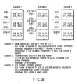
- a SOB number to be played back (referenced) is set at CELL, and a plurality of methods for numbering SOB may be considered as shown in FIG. 36.
- First is a method for assigning and controlling serial numbers in order described in STR_FI; second is a method for expression with STR_F number and SOB number; and third is a method for freely assigning SOB number and setting the SOB number in SOB_GI.
- the first method since a number is determined by default, the corresponding information contained in the SOBI is not required. However, SOB number must be reassigned every time SOB is added.
- the second method since a number is determined by default, the corresponding information contained in the SOBI is not required.
- STR_F number as well as SOB number is required in CELLI.
- SOB number is required for both of the SOBI and the CELLI, but the degree of freedom is the highest.
- FIG. 37 is a view illustrating an example of how a data unit (SOBU) for a stream object shown in FIG. 1F or FIG. 2 is configured.
- SOBU data unit
- One SOBU 134 comprises one or more packet groups 140.
- Each packet group 140 comprises: a packet group header (128 bytes) 161; one or more packet arrival times PAT (4 bytes) 163 (170 PATS in this case); and MPEG-TS packets (188 bytes) 162 equal to PAT in number (170 packets in this case).
- a pair of PAT 163 and MPEG-TS packet 162 has the PAT 163 at the beginning thereof.
- the PAT 163 indicates a time when each MPEG-TS packet 162 has arrived at device.
- the packet group header 161 comprises: a synchronizing pattern 151; display control information (DCI: Display Control Information) and copy generation control information (or copy control information CCI: Copy Control Information) 152; and manufacturer's information (MNI: Manufacturer's information) (or manufacturer information MNFI) 153.
- DCI Display Control Information
- CCI Copy Control Information
- MNI Manufacturer's information
- each MPEG-TS packet 162 comprises: a 4-byte header 170 and an adaptation field and/or a payload 180.
- the header 170 comprises: a synchronizing byte 171; a transport error indicator 172; a payload unit start indicator 173; a transport priority 174; a packet identifier (PID) 175; a transport scramble control 176; an adaptation field control 177; and a continuity index 178.
- PID packet identifier
- FIG. 38 is a view illustrating an example of how the DCI_CCI 152 included in the packet group header 161 shown in FIG. 37 is configured.
- Validity information (DCI_CCI_SS) comprises 1 byte. Among them, 1-bit DCI_SS indicates that the setting is invalid when it is 0, and indicates that the setting is valid when it is 1. 4-bit CCI_SS indicates whether APS is valid or invalid at bit 0; indicates whether EPN and ICT are valid or invalid at bit 1; indicates whether CGMS is valid or invalid at bit 2; and indicates whether Retention is valid or invalid at bit 3.
- DCI display control information
- FIG. 39 is a view illustrating examples (Example 1 and Example 2) of how each copy control information CCI included in the DCI_CCI 152 of FIG. 38 is configured.
- APS denotes an Analog Protection System, and assumes a macro-vision system (registered trademark) in such the embodiment.
- FIG. 40 is a view illustrating an example of how the MNI 153 included in the packet group header shown in FIG. 37 is configured.
- the MNI 153 comprises: MNF_ID_DATA 1531 and MNF_DATA 1532.
- the MNF_ID_DATA 1531 comprises: MNF_SS (1: MNF_DATA exists, 0: MNF_DATA does not exist); and MNF_ID_N.
- the MNF_ID_N is expressed with number (3 bits) indicating MNF_ID in MNF_ID_TBL (refer to FIG. 8) in STR_FI.
- the MNF_DATA is provided as a data region which can be freely set on a manufacturer by manufacturer basis.
- the region MNFI (Manufacturer's Information) 153 is provided in the Packet Group Header 161.
- a storage capacity is limited in the Packet Group Header 161 in object information.
- an MNF_ID_TBL 13224 group is provided in the STR_FI 1322 (refer to FIG. 6).
- the SOBI 13223 specifies TBL which one uses from the group, and the Packet Group Header 161 specifies a number (MNF_IDN) indicating the target MNF_ID (ID of company having undergone recording operation) 132241 in that TBL, thereby enabling processing in the header having its limited capacity.
- MNF_IDN the number of MNF_ID (ID of company having undergone recording operation) 132241 in that TBL, thereby enabling processing in the header having its limited capacity.
- FIG. 41 is a block diagram showing an example of an apparatus which records/plays back audio/video (AV) information (digital TV broadcasting program, etc.) in an information recording medium (optical disk, hard disk, etc.) utilizing a data structure according to one embodiment of the present invention.
- AV audio/video
- the apparatus (digital video recorder/streamer) comprises a main MPU unit 80, key input unit 103, remote controller receiver 103b which receives user operation information from a remote controller 103a, display unit,104, decoder unit 59, encoder unit 79, system time counter (STC) unit 102, data processor (D-PRO) unit 52, temporary storage unit 53, disk drive unit 51 which records/plays back information with respect to a recordable optical disk 100 such as a DVD-RAM, hard disk drive (HDD) 100a, video mixing (V-mixing) unit 66, frame memory unit 73, D/A converter 67 for analog TV, analog TV tuner unit 82, terrestrial digital tuner unit 89, set top box (STB) unit 83 connected to a satellite antenna 83a, terrestrial tuner unit 82, and emergency broadcasting detection unit 108 which is connected to the STB unit 83 and which sets power activation instruction and emergency broadcasting information with respect to the MPU unit 80, on detecting the emergency broadcasting
- STC system time
- the STC unit 102 is configured to count clocks on a 27 MHz base in accordance with the PAT_base of FIG. 37.
- the STB unit 83 decodes received digital broadcasting data to generate an AV signal (digital), and sends the AV signal to a TV monitor 68 via the encoder unit 79, decoder unit 59, and D/A converter 67 in the streamer, so that the contents of the received digital broadcasting can be displayed.
- the STB unit 83 is also configured to be capable of sending the decoded AV signal (digital) directly to the V-mixing unit 66 and sending an analog AV signal to the TV monitor 68 from the V-mixing unit 66 via the D/A converter 67.
- the apparatus of FIG. 23 constitutes a recorder comprising functions of both video recording and stream recording
- the apparatus comprises components (IEEE 1394 I/F, etc.) unnecessary in the video recording or components (an A/D converter 84 for AV input, audio encoder unit 86, video encoder unit 87, etc.) unnecessary in the stream recording.
- the encoder unit 79 comprises the A/D converter 84, video encoder unit 87, input switch selector 85 to the video encoder unit 87, audio encoder unit 86, sub-picture encoder unit (not shown, but if necessary), formatter unit 90, and buffer memory unit 91.
- the decoder unit 59 comprises a demultiplexer 60 which contains a memory 60a, video decode unit 61 which contains a memory 61a and a generator 62 of a reduced-scale picture (thumbnail, etc.), sub-picture (SP) decode unit 63, audio decode unit 64 which contains a memory 64a, TS packet transfer unit 101, video processor (V-PRO) unit 65, and D/A converter 70 for audio.
- An analog output (monaural, stereo, or AAC 5.1CH surround) from the D/A converter 70 is input into an AV amplifier and the like (not shown), and the necessary number of speakers 72 are driven.
- stream data to be recorded is sent to the D-PRO unit 52, simultaneously sent also to the decoder unit 59, and can be reproduced.
- the MPU unit 80 sets the decoder unit 59 at the time of playback, and thereafter the decoder unit 59 automatically performs a playback process.
- the D-PRO unit 52 forms an ECC group, for example, every 16 packs, attaches an ECC, and sends the data to the drive unit 51. Additionally, when the drive unit 51 is not prepared for the recording into the disk 100, the data is transferred to the temporary storage unit 53. The apparatus waits until preparations for recording the data are made. In a stage in which the preparations are made, the recording is started. Here, since the temporary storage unit 53 holds the recording data for several minutes or more at a high-speed access, a large-capacity memory is assumed. This temporary storage unit 53 can be configured utilizing a part of the HDD 100a.
- the MPU unit 80 is configured in such a manner as to be capable of reading/writing the data with respect to the D-PRO unit 52 through a microcomputer bus for exclusive use in order to read/write the data with respect to a management area of a file or the like.
- the optical disk 100 for example, DVD-RAM/-RW/-R/Blue media (recordable media using blue laser) or the like, is assumed as a recording medium, and the hard disk drive (HDD) 100a (and/or a large-capacity memory card (not shown), etc.) is assumed as an auxiliary storage device.
- the hard disk drive (HDD) 100a and/or a large-capacity memory card (not shown), etc.
- a way of using these plurality of mediums is, for example, as follows. That is, the stream recording is performed with respect to the HDD 100a utilizing the data structure (format) of FIGS. 1A to 40. Moreover, in the stream recording contents recorded in the HDD 100a, the program desired to be stored by the user is subjected to the stream recording (direct copying or digital dubbing) as such in the disk 100 (in a case where the copying is not prohibited by the copy control information CCI). In this case, only desired program having a quality equivalent to an original quality of the digital broadcasting can be recorded in the disk 100. Furthermore, since the data structure of the present embodiment is utilized in the stream recording contents copied to the disk 100, special playback such as time search is facilitated even in the stream recording.
- a concrete example of a digital recorder (streamer/video recorder comprising a combination of DVD-RAM/-RW/-R/Blue media with the HDD) having the above-described characteristics is the apparatus of FIG. 41.
- the digital recorder of FIG. 41 roughly comprises the tuner unit 82, 83, 89, disk unit 100, 100a, encoder unit 79, decoder unit 59, and control unit 80.
- Satellite digital TV broadcasting is broadcasted from a broadcasting station through a communication satellite.
- the broadcasted digital data is received and reproduced by the STB unit 83.
- the STB unit 83 is a unit which extends and reproduces the scrambled data based on a key code supplied from the broadcasting station. At this time, the scrambling from the broadcasting station is descrambled.
- the data is scrambled in order to prevent the broadcasted program from being illegally heard/seen by a user who does not contract reception with respect to the broadcasting station.
- the broadcasted digital data is received by a tuner system (not shown).
- the scrambling is descrambled by a digital extension unit
- the received data is decoded by an MPEG decoder unit
- the data is converted into a TV signal by a video encoder unit
- the TV signal is sent to the outside via the D/A converter 67. Accordingly, the digital broadcasting program received by the STB unit 83 can be displayed by the analog TV monitor 68.
- Terrestrial digital broadcasting is received and processed in the same manner as in the satellite broadcasting except that the broadcasting does not go through the communication satellite (and the data is not be scrambled in free broadcasting). That is, the terrestrial digital broadcasting is received by the terrestrial digital tuner unit 89. When the broadcasting is reproduced as such, the decoded TV signal is sent to the outside via the D/A converter 67. Accordingly, the digital broadcasting program received by the terrestrial digital tuner unit 89 can be displayed by the analog TV monitor 68.
- the terrestrial digital tuner unit 89 and the STB unit 83 supplies command/error information to a system bus (MPU unit 80).
- the terrestrial analog broadcasting is received by the terrestrial tuner unit 82.
- the received analog TV signal is sent to the outside. Accordingly, the analog broadcasting program received by the terrestrial tuner unit 82 can be displayed by the TV monitor 68.
- An analog video signal analog-input from an external AV input 81 can be sent straight to the TV monitor 68, but may be once A/D converted by the A/D converter 84, thereafter returned to the analog video signal by the D/A converter 67, and sent to an external TV monitor 68.
- the (digital time base collected) analog video signal that does not have any jitter can be output on the side of the TV monitor 68.
- the digital video signal digital-input from the digital I/F (IEEE 1394 interface) 74 is sent to the external TV monitor 68. Accordingly, the digital video signal input in the digital I/F 74 can be displayed in the TV monitor 68.
- the satellite digital broadcasting, terrestrial digital broadcasting, or a bit stream (MPEG-TS) input from the digital I/F 74 can be stream-recorded as the stream object 132 of FIG. 1E in the stream object group recording area 131 (FIG. 1D) of the disk 100 (and/or the HDD 100a).
- MPEG-TS bit stream
- the terrestrial analog broadcasting or the analog video signal from the AV input 81 can be video-recorded in the VR object group recording area 122 (FIG. 1D) of the disk 100 (and/or the HDD 100a).
- the apparatus can be configured in such a manner that the terrestrial analog broadcasting or the analog video signal from the AV input 81 is once A/D converted, and the stream recording is performed, not the video recording.
- the apparatus may be configured in such a manner that the satellite digital broadcasting, the terrestrial digital broadcasting, or the bit stream (MPEG-TS) input from the digital I/F 74 is subjected to the video recording, not the stream recording (after necessary format conversion is performed).
- MPEG-TS bit stream
- the MPU unit 80 has a management data generator 80B of the stream recording and video recording, prepares various management information using a work RAM 80A as a work area, and appropriately records the prepared management information in the AV data management information recording area 130 of FIG. 1D.
- the MPU unit 80 reproduces the management information recorded in the AV data management information recording area 130, and performs various controls (FIGS. 41 to 69) based on the reproduced management information. It is to be noted that manufacture ID information or the like of the apparatus of FIG. 41 can be written beforehand in the ROM 80C of the MPU unit 80.
- the medium comprises a management area 130 and a data area 131.
- the data is separated into a plurality of object data (stream objects (SOBs)) and recorded in the data area, and each object data comprises a set of data units (SOBUs).
- one data unit (SOBU) comprises pack groups obtained by pack-grouping digital broadcasting signals for each TS packet, conforming to the MPEG-TS, by a plurality of packs (see FIGS. 1F and 37).
- the management area 130 comprises EX_PGC information (EX_PGCI) as information which manages the playback procedure, and the EX_PGC information (EX_PGCI) comprises cell information (CI). Furthermore, the management area 130 has information which manages the object data (stream object (SOB)).
- EX_PGC information EX_PGCI
- EX_PGCI EX_PGC information
- CI cell information
- the management area 130 has information which manages the object data (stream object (SOB)).
- the apparatus of FIG. 41 can perform the stream recording in addition to the video recording with respect to the medium 100 (100a) having the above-described data structure.
- the MPU unit 80 is configured in such a manner as to have a service information fetching section (not shown, firmware constituting a part of the management data generator 80B).
- the MPU unit 80 is also configured in such a manner as to have an attribute information generator (not shown, firmware constituting a part of the management data generator 80B) which prepares attribute information (PCR_LB number, etc.) based on the information taken by the service information fetching section.
- the signals at the time of the recording flow, for example, as follows.
- the TS packet data received by the STB unit 83 (or the terrestrial digital tuner unit 89) is packet-grouped by the formatter unit 90, and stored into a work area (buffer memory unit 91).
- a certain amount of data is stored (in a stage in which the data for one or integer times CDA is stored)
- the data is recorded in the disk 100.
- the packets are grouped every 170 packets, and a packet group header is prepared.
- the analog signal input via the terrestrial tuner unit 82 or a line input is digital-converted by the A/D converter 84.
- the digital signal is input into the respective encoder units 86 and 87.
- the video signal is input into the video encoder unit 87, the audio signal is input into the audio encoder unit 86, character data such as character broadcasting is input into an SP encoder unit (not shown), the video signal is MPEG-compressed, the audio signal is subjected to AC3 compression or MPEG audio compression, and the character data is subjected to run-length compression.
- each packet is formed into the block, further multiplexed, and sent to the D-PRO unit 52.
- the D-PRO unit 52 prepares an ECC block every 16 (or 32) blocks, attaches error correction data, and records the data in the disk'100 by the disk drive unit 51.
- the drive unit 51 in a case where the drive unit 51 is seeking the data or jumps to another track, the data is input into the HDD buffer unit 53 in a busy state, and the apparatus waits until the preparations of the RAM drive unit 51 are made. Furthermore, the drive unit 51 prepares each delimitation information during the recording, and periodically sends the information to the MPU unit 80 (GOP head interruption, etc.). As the delimitation information, there are the LB number of the VOBU (SOBU), end address of the I picture from the VOBU (SOBU) head, playback time of VOBU (SOBU) and the like.
- SOBU LB number of the VOBU
- SOBU end address of the I picture from the VOBU
- SOBU playback time of VOBU
- the data is read from the disk 100 by the drive unit 51, errors are corrected by the D-PRO unit 52, and the data is input into the decode units 61, 63, and 64.
- the MPU unit 80 determines whether the type of the input data is VR data or SR data (determined by Cell TYPE), and sets the type to the decoder unit before playback. In the case of the SR data, the MPU unit 80 determines PMT_ID to be played back from cell information CI to be played back, determines the PID of each item (video, audio, etc.) to be played back from the corresponding PMT, and sets the PID to the decoder unit 59.
- the decoder unit 59 sends each TS packet by the demultiplexer 60 to each decoder unit 61, 63, and 64 based on the PID. Furthermore, the data is sent to the TS packet transfer unit 101, and transmitted to the STB unit 83 (1394 I/F 74) in the form of the TS packet in accordance with the arrival time. Each decoder unit 61, 63, and 64 performs the decoding, and the data is converted into the analog signal by the D/A converters 67 and 70, displayed in the TV monitor 68, and output from the speaker 72.
- pack data read from the disk 100 is'analyzed by the demultiplexer 60.
- the pack includes TS packet
- the pack is transmitted to the TS packet transfer unit 101 and further supplied to each decoder unit 61, 63, and 64 to be played back.
- the packet transfer unit 101 transmits only TS packets at the same time interval as reception time interval.
- the STB unit 83 decodes the packet to produce AV data which is displayed on the TV 68 through a video encoder unit in a streamer.
- an MPEG-TS scheme which is a common basic format is divided into a packet control data portion and a payload.
- data targeted to be played back is included in a state in which the data is scrambled.
- PAT Program Association Table
- PMT Program Map Table
- SI Service Information
- a variety of control information can be prepared by utilizing PMT or SI (SDT: Service Description Table, EIT: Event Information Table, BAT: Bouquet Association Table).
- Playback objects include: MPEG video data; Dolby (registered trademark); AC3 audio data and MPEG audio data; data broadcast data and the like. Further, the playback objects further include information such as PAT, PMT, or SI (such as program information) required for playback. PID (Packet Identification) of PMT for each program is included in the PAT, and PID of video data or audio data is recorded in the PMT.
- PAT Packet Identification
- Normal playback procedures for the STB (Set Top Box) unit 83 are as follows.
- PAT is read at a start time of a target program.
- PID of PMT belonging to a desired program is determined based on that data, and a target PMT is read out in accordance with that PID.
- PID of a video or audio packet to be played back the packet included in the target PMT, is determined; a video or audio attribute is read out by PMT or SI, and the read-out attribute is set to each decoder.
- the video or audio data is isolated and played back in accordance with PID.
- PAT, PMT, SI and the like are transmitted every several hundreds milliseconds for use in intermediate playback.
- FIG. 42 is a flow chart (whole operating process flow) illustrating an example of a whole operation in the apparatus of FIG. 41.
- the data processes used here includes 5 processes, i.e., a recording process (ST22), a playback process (ST24), a data transfer process (such as a digital output process to STB) (ST26), a program setting process (ST20), and an edition process (ST28).
- a recording process ST22
- ST24 a playback process
- ST26 data transfer process
- ST20 program setting process
- ST28 edition process
- the MPU unit 80 when the apparatus of FIG. 41 is powered ON, the MPU unit 80 performs initial setting (at the time of factory shipment or after the user setting) (ST10) and display setting (ST12); and waits for the user operation (key input).
- the MPU unit 80 interprets the contents of that key input (ST16). According to a result of this input key interpretation, the following four data processes are properly performed.
- a program setting process is performed (ST20).
- a recording process is performed (ST22).
- a playback process is performed (ST24).
- a digital output process is performed (ST26).
- an edition process is performed (ST28).
- a process for digital output to STB is performed in parallel during the playback process (ST24).
- the new program setting process can be configured to be performed in parallel during the recording process (ST22) which is not timer reservation recording.
- a playback process (ST24) and a digital output process (ST26) can be configured so as to be performed in parallel during the recording process (ST22).
- a disk edition process (ST28) can be configured so as to be performed during HDD recording.
- FIG. 43 is a flow chart (editing operation process flow) illustrating an example of the edition process (ST28) shown in FIG. 42.
- any one of four processes ST228A to ST228D can be performed (ST280).
- ST282A entry point edition process
- ST282B copying/moving process
- ST282C deletion process
- ST282D play list preparation process
- ST284 the date and time of program update using this edition is set in each item of control information (EX_PGI, EX_IT_TXT, ET_MNFI) (ST284) .
- this program update date and time (refer to FIG. 35) may be set.
- the VOBI and/or SOBI edit time can be set at SOB_EDIT_TIME or the like (not shown).
- manufacturer ID of device having made any of operations in ST282A to ST282D may be set at editor ID (LAST_MNF_ID) 13326 of FIG. 35.
- editor ID LAST_MNF_ID
- this editor ID can be set (or updated) based on ID information on device used at that time.
- FIG. 44 is a flow chart (initial setting process flow example 1) illustrating an example of initial setting (ST10) shown in FIG. 42. This initial setting process is as follows.
- a disk check is made (ST40), and when an error occurs, this check process is terminated.
- VMG is read (ST44).
- Profile information is read (ST46), and it is determined whether or not a region is matched (ST48).
- region is not matched (NO in ST48)
- setting is changed so as not to play back SOB and to display a warning message such as "The region code is not matched so that some contents may not be played back" (ST50).
- option information is read, and setting is changed so as to operate in accordance with an operation chart shown in FIG. 45 (ST52).
- FIG. 45 is a view showing an operation chart for specifying a combination between a basic format (Base) and one or more options (Option 1, Option 2) based on a relationship between a disk used and a playback operation (a relationship chart between an option and a playback operation).
- Base basic format
- Options 1 options
- FIG. 45 is a view showing an operation chart for specifying a combination between a basic format (Base) and one or more options (Option 1, Option 2) based on a relationship between a disk used and a playback operation (a relationship chart between an option and a playback operation).
- Base is SD_MPEG-2 PS + SD_new AVC PS
- a long time signal can be recorded in a DVD-RAM disk in accordance with conventional DVD-VR (DVD video recording) specifications.
- Option 1 is HD_new AVC PS + HD_MPEG-2 PS
- data can be recorded in an AOD (Advanced optical Disc) disk with high quality which has not been achieved by conventional DVD-VR specifications.
- Option 2 is compatible with digital broadcasting and is compatible with MPEG-2 TS, digital broadcast data can be recorded as a stream.
- what is to be introduced can be selected according to their respective equipment purposes.
- ⁇ indicates that processing can be partially performed, and "?" indicates that a function of the corresponding option can be utilized. Because it is free as to what is specifically associated with "?” shown in plurality (unless otherwise specified in accordance with a standard or the like), although no limitation applies in particular, such an example is as described above.
- methods for delimiting Base and Option include: a method for defining a portion supported in conventional VR specifications as Base, defining digital broadcast compatibility as Option 2, and defining the remaining HD self-recording and self-playback compatibility + new recording (sound) format as Option 1, as shown in FIG. 46; and a method for defining SD compatibility as Base, defining digital broadcast compatibility as Option 2, and defining the remaining HD auto self-recording and self-playback compatibility + new audio CODEC (such as AAC) as Option 1, as shown in FIG. 47; and a method for defining SD compatibility as Base, defining digital broadcast compatibility + new audio CODEC (such as AAC) as Option 2, and defining the remaining HD self-recording and self-playback compatibility as Option 1.
- AAC or new CODEC compatible with MEPG-2 PS is believed to be required for converting digital broadcasting into PS.
- these AAC or new CODEC is added only when digital broadcasting is supported.
- the contents to be supported by Options are believed to be different from each other in accordance with a digital broadcasting scheme to be recorded, the scheme indicated by a value of AP_FORMAT_1.
- a digital broadcasting scheme to be recorded the scheme indicated by a value of AP_FORMAT_1.
- an AAC scheme is used as a standard audio format.
- an MPEG-audio format is provided as standard. Therefore, the formats to be supported are different from each other, and the formats to be supported by each option are changed in association with this digital broadcasting to be recorded.
- FIGS. 49 and 50 are flow charts illustrating an example of a recording operation in the apparatus of FIG. 41. Data processing during stream recording is as follows (refer to FIGS. 49 to 63).
- a program to be recorded is determined by using an EPG (Electronic Program Guide) in a program setting process, receiving is started, and recording of the determined program is performed.
- EPG Electronic Program Guide
- the MPU unit 80 When the MPU unit 80 receives a recording command from the key input unit 103, the MPU unit 80 determines a region for reading and writing control data from the drive unit 51. At this time, the file system is checked (ST100), and it is determined whether or not a remaining capacity is enough to record an object (ST102). When recording is enabled, a preprocessing of recording such as preparation of VMG or setting of management regions is performed (ST105: Refer to FIG. 55). When recording is not enabled, the fact is indicated to the user, e.g., by displaying a warning message "no recording space remains" (ST104), and processing is canceled.
- a recording target is a digital broadcast content (ST106) and when no error occurs (No in ST111), the determined region is set in a management region so that the region is written. Then, preparation for data recording is performed. Particularly, the STC unit 102 is reset, a video data write start address and a write instruction are set to the drive unit 51, the formatter is initialized, and a delimitation of CELL, SOBU, PG, Packet Group is initially set (ST112).
- time resetting is performed at the STC unit 102.
- the STC unit 102 carries out recording and playback using the system timer based on the reset value as a reference.
- PAT of a program to be recorded is read; PID for capturing PMT of the target program is determined; the target PMT is read; and PID of each item of data (video, audio) to be decoded (recorded) is determined.
- PAT and PMT are stored in the work RAM unit 80A of the MPU unit 80, and the stored PAT and PMT are written into control information.
- VMG file data is written, and information required for VMGI is written.
- Recording setting is performed for each section (ST114). At this time, the setting of delimitation of each item of data at the formatter unit 90 or the setting of receiving a TS packet is provided. At this time, PID of data to be recorded is set so as to record only the target video stream
- setting is provided to the buffer 53 so as to start retention of the TS packet (ST116).
- profile information is set in accordance with a configuration of TS.
- SOB_ESIs are prepared from PMT by the number of streams (ST120: Refer to FIG. 56).
- the formatter unit 90 starts a buffer fetch operation (ST130), as shown in FIG. 51.
- delimitation information is periodically stored in the work RAM 80A of the MPU unit 80 (before the buffer RAM 91 of the formatter unit 90 becomes full) (ST144 and ST146).
- the delimitation information used here denotes SOBU delimitation information, and includes an SOBU start address, an SOBU pack length, an I-picture end address, and an SOBU arrival time (ATS).
- ST148 it is determined whether or not recording is terminated (whether or not the recording end key has input or whether or not the remaining free space becomes full).
- the remaining delimitation information is read from the formatter unit 90, and the read information is added to the work RAM 80A. Then, these items of data are recorded in control data (VMGI), and further, the remaining information is recorded in the file system.
- FIG. 51 is a flow chart (buffer fetch process flow) illustrating an example of the buffer fetch process (ST130) shown in FIG. 50.
- TS packet data received at the STB unit 83 or terrestrial digital tuner 89
- the work RAM 80A After packet-grouped at the formatter unit 90.
- the data At a time point when a predetermined amount of the packet data is accumulated (at a stage when the data is accumulated by one CDA or integer multiples thereof), the data is recorded in the disk 100.
- operation is performed as follows.
- grouping is performed on a 170 packets by packets basis, and a packet group header is prepared.
- modification of STC is performed by setting the value of PCR to STC (ST1302 and ST1304).
- Sync_Pattern: 00ffa5a5 is set at the start of a packet group (ST1308).
- a TS packet arrival time is defined as PAT
- the PAT is allocated in the TS packet group header (ST1308).
- the received TS packet is set in the TS packet data area.
- FIG. 52 is a flow chart (CPI preparation process flow) illustrating an example of the CPI setting process (ST1330) shown in FIG. 51.
- the CPI setting process will be described below.
- Previous CPI is read out (ST13300).
- the previous CPI is the same as SOBI if the CPI is the header of SOB.
- copy information digital copy control descriptor and contents utilization descriptor
- PMT and EIT latest packet group
- copy information When no copy information is present in the received TS packet, information identical to the previous pack is generated as copy information (ST13304).
- CCI When no copy information is present in the received TS packet, CCI is set to be copy free.
- FIG. 53 is a view showing a data structure of a packet group in a process (packet group aligning process) at step ST13308 of FIG. 52.
- CPI CCI and/or DCI
- the packet group is temporarily delimited. Then, as shown in FIG. 53, the remaining pack is padded with dummy data, and is set so as to be a next packet group. Namely, an aligning process is performed so that CCI or DCI does not change in the packet group.
- FIG. 54 is a flow chart (MMFI preparation process flow) illustrating an example of the MNFI setting process (ST1331) shown in FIG. 51. The MNFI preparation process will be described with reference to FIG. 54.
- step ST13310 it is determined whether or not MNF_DATA to be stored exists in this packet group. When it does not exist, processing goes to step ST13314 in which 0 is set in MNF_SS, MNF_ID_N, and MNF_DATA, and this process is terminated (refer to FIG. 40 as well).
- processing goes to step ST13312 in which 1 is set in MNF_SS, and then, processing goes to step ST13316 in which an ID number to be used is selected from the table MNF_ID_TBL, and the number is set in MNF_ID_N.
- step ST13318 in which data to be recorded in MNF_DATA is set, and this process is terminated.
- FIG. 55 is a flow chart (recording preprocessing) illustrating an example of preprocessing before starting recording in the disk-shaped information storage medium (for example, optical disk using blue laser) shown in FIG. 1. Recording preprocessing is performed as follows.
- VMG Voice over the Home Multimedia Subsystem
- VMGI which is its control information is read in the work memory (ST1110), and profile information (FIGS. 8 and 10 and the like) is read. Then, a recording operation setting process is performed (ST6070). Then, processing goes to step ST1120B in which it is determined whether or not contents to be recorded from now on are digital broadcasting. When they are not digital contents, processing goes to step ST1130A.
- a region is checked (ST1123).
- a warning message "Region code is invalid. Recording cannot be carried out.” is displayed (ST1125) and the operation is terminated.
- processing goes to step ST1130B.
- step ST1126 VMG is prepared, and the default value of this apparatus is recorded in profile information (FIGS. 8 and 10 and the like) (ST1126).
- the object file When an SOB file is present, the object file is set so as to be recorded following the SOB. When an SOB file is not present, a new SOB is created and the object file is set so as to be recorded following the new SOB (ST1130B).
- FIG. 56 is a flowchart (ESI preparation process flow) showing one example of contents of the stream information (ESI) preparation process (ST120) shown in FIG. 50.
- a stream type in PSI or SI is checked (ST1201).
- the PMT is included in the stream to be recorded, and the stream type is described in the PMT.
- the ES_PID, STREAM_TYPE, and COMPONENT_TAG are set to the PMT, and STREAM_COMPONENT, COMPONENT_TYPE are set from the component descriptor. Thereafter, the process advances to step ST1220.
- attributes sampling frequency, quantization bit number, channel number, etc.
- the ES_PID, STREAM_TYPE, and COMPONENT_TAG are set to the PMT, and STREAM_COMPONENT, COMPONENT_TYPE, SIMULCAST_GP_TAG, LANG_CDE are set to the audio component descriptor. Thereafter, the process advances to step ST1220.
- the ES_PID, STREAM_TYPE, and COMPONENT_TAG are set to the PMT, and DATA_COMP_ID, AD_DAT_COMP_INFO are set to a data encoding descriptor. Thereafter, the process advances to step ST1220.
- CP_CTRLR_INFO copy control information in SOB_ESI
- FIG. 57 is a flowchart (stream file information preparation process flow) showing one example of contents of the stream file information (STR_FI) preparation process in the recording end process (ST150) shown in FIG. 50.
- STR_FI stream file information
- a recording start time is set to SOB_REC_TM, SOB_REC_TM_SUB, and start PTM (SOB_S_PTM) and end PTM (SOB_E_PTM) are fetched from the stream and set (ST1502).
- a clock the STC unit 102 of FIG. 41
- TDT time data table
- PCR_POS_SHIFT is set in accordance with a recording rate (ST1504).
- the type of the stream is a transport stream (ST1506).
- ST1506 transport stream
- TS stream transport stream
- ARIB ARIB or DVB in a broadcasting system
- "16" is set to PKT_GRP_SZ
- "0xAA” is set to PKT_Ns
- a country code of the apparatus is set to the country code (ST1508).
- ST1510 a value corresponding to the format to be recorded in the PKT_GRP_SZ is set
- a value corresponding to the format to be recorded in the PKT_Ns is set
- the country code of the apparatus is set to the country code (ST1510).
- 1 (ISDB-S) is set to AP_FORMAT in the case of ARIB
- 2 is set to AP_FORMAT in the case of ATSC
- 3 is set to AP_FORMAT in the case of DVB
- the PAT at the recording start is read from a work memory
- TS_ID, NETWORK_PID, PMT_ID (PID of the PMT for use in the present SOB) are set (ST1514).
- the SOB number is set (Example 3).
- the PMT, NIT, EIT at the recording start are read from the work memory, and Program_number (SERVICE_ID in the PMT), Format_Id, version (value of REG_DES), PCR_PID, ESOB_Es_Ns, V_ES_Ns, and A_Es_Ns are set.
- the PID having a smallest component tag value (additionally, the value set by the component group descriptor is preferential) is set to DEF_PID.
- Profile information is set based on default value of a recorder (Example 2).
- a GPI setting process (described later) (ST1530), TMAPI setting process based on each item of delimitation information (described later) (ST1540), and an MNF_ID_TBL setting process (described later) (ST1545) are performed.
- An LB address having started recording is set in ADR_OFS (FIG. 19) and CP_CTL_IFO is prepared based on a whole CP information of the PMT (ST1550).
- An edit date and time is set (ST1554).
- a default PID is set. The default PID corresponds to a PID of a component tag value 00 or PID of a stream which corresponds to a component tag described in a main component group in the case of a multi-view TV.
- FIG. 58 is a flow chart illustrating an example (Example 1) of the GPI setting process ST1530 of FIG. 57.
- the GPI setting process contains two types of data schemes. A first method relating to the first data scheme will be described below with reference to FIG. 58.
- a stream type is checked in various aspects (steps ST15300A, ST15304A, and ST15308A).
- Es_Tmap_Ns is set such that TMAPI is prepared for each program.
- SOB_TY is set such that GPI is present.
- the number of programs is set to GPI_SRP_Ns.
- 03 is set to GPI_TY and all is set as "main”.
- Different values are set to BLOCK_NUMBER for each program.
- the number of PIDs and value of each PID are set such that GPI is prepared for each program (ST15302A).
- ES for preparing TMAPI is set based on a hierarchical descriptor in EIT.
- Es_Tmap_Ns is set.
- SOB_TY is set such that GPI is present.
- Data in a low hierarchy is registered as another GP and 2 is set to GPI_SRP_Ns.
- 02 is set to GPI_TY and data in a high hierarchy is set as "main” and remaining is set as "sub”.
- the same value is set to BLOCK_NUMBER for a low hierarchy and a high hierarchy.
- the number of PIDs and value of each PID are set such that GPI is prepared for each hierarchy.
- PID for audio is common for all hierarchies (ST15306A).
- ES for preparing TMAPI is set based on a hierarchical descriptor in EIT.
- Es_Tmap_Ns is set.
- SOB_TY is set such that GPI is present.
- Data in each group are registered as other GPs and the number of groups is set to GPI_SRP_Ns.
- 01 is set to GPI_TY and data of a main group is set as "main” and remaining is set as "sub”.
- the same value is set to BLOCK_NUMBER for each group.
- the number of PIDs and value of each PID are set such that GPI is prepared for each group (ST15310A).
- step ST15308A When NO is determined at step ST15308A, 1 is set to Es_Tmap_Ns and SOB_TY is set such that GPI is absent (ST15312A).
- step ST15314A It is determined whether or not there is a remaining GP (ST15314A). When there is a remaining GP, the processing is returns to step ST15300A and when no remaining GP exists, this process is terminated.
- FIG. 59 is a flow chart illustrating the TMAP setting process ST1540 of FIG. 57.
- the TMAP setting process is as follows.
- a structure of VOB/SOB is determined (ST15400).
- the number of TMAPs is determined in consideration of the number of GPs, etc..
- ES_PID which is prepared for each TMAP is determined.
- one TMAP is added (ST15402). However, there is no need for always assigning one TMAP to one GP. When no setting is provided, playback, search, special playback, and the like are performed by utilizing TMAP of GP to which the same MAIN_GP or the same BLOCK_NUMBER is assigned.
- a SOB/VOB start time and end time; a start time and end time for each TMAP; the number of SOB_ENTRYs; a TMAP number to be registered to TMAPT are set based on delimitation information.
- a TMAP to be prepared for TMAPT is added, and ENTRY information is prepared based on delimitation information.
- TMAPT information may be stored in another file (FIG. 3 or the like) and may be added at the end of an IFO file (FIG. 4 or the like).
- TMAPT information may be stored in another file (Example 1; FIG. 3) and may be added at the end of an IFO file (Example 1; FIG. 4).
- an updated date and time information for an edited TMAP is set to STAMP/VTMAP_LAST_MOD_TM.
- FIG. 60 is a flow chart illustrating an example (Example 1) of an MNF_ID_TBL setting process (ST1545) of FIG. 57.
- the MNF_ID_TBL setting process is performed as follows.
- TBL When no TBL exists, it is determined whether or not a free space is present in TBL (ST15456). When such a free space exists, manufacturer ID of this device is set in the free space (ST15460). When no free space is present in TBL, TBL in which the present ID is set is added and MNF_ID_TBL_Ns is incremented (ST15458). At step ST15462, the set TBL number is set in SOBI, and this process is terminated.
- FIG. 61 is a flow chart illustrating the VOB/SOB structure setting process ST15400 of FIG. 59. The VOB/SOB structure setting process will be described below.
- a recording time after recording is checked (ST154000).
- processing goes to step ST154002.
- processing goes to step ST154003.
- processing goes to step ST154004.
- VOB/SOBU_PB_TM_RNG VOBU/SOBU_ENTRY is prepared so that SOBU ranges from 0.4 seconds to 1 second based on delimitation information (information on 0.4 seconds to 1 second), and this process is terminated.
- VOB/SOBU_PB_TM_RNG 1 is set in VOB/SOBU_PB_TM_RNG, VOBU/SOBU_ENTRY is prepared so that SOBU ranges from 1 second to 2 seconds based on delimitation information (information on 0.4 seconds to 1 second); and this process is terminated.
- step ST154004 2 is set in VOB/SOBU_PB_TM_RNG, VOBU/SOBU_ENTRY is prepared so that SOBU ranges from 2 seconds to 3 seconds based on delimitation information (information on 0.4 seconds to 1 second); and this process is terminated.
- FIG. 62 is a flow chart illustrating the CP_CTL_INFO preparation process ST1220 of FIG. 56.
- the CP_CTL_INFO setting process will be described below.
- step ST12200 It is determined at step ST12200 whether or not there is a digital copy control descriptor in latest program map tables PMT, EIT (SI, PSI). When there is the descriptor, the digital copy control descriptor is fetched at step ST12204. At step ST12206, copy free, copy protect in CCI are set as such, the copy protect is set in a case where one copying operation is permitted, and an analog copy control value is set to APS. When there is not any copy descriptor, at step ST12202, the copy free is set to CCI, and non-APS is set to the APS.
- Step ST12208 It is determined at step ST12208 whether or not there is a contents use descriptor in the latest program map tables PMT, EIT (SI, PSI).
- the descriptor is fetched at step ST12212, and ICT (resolution limitation) and EPN (internet output limitation) are set at step S12214.
- the value in the SI, PSI is set to the ICT, 0 (prohibition or encryption) is set to the EPN because an internet output is prohibited in the digital broadcasting, and a value of Retention (1: temporary storage prohibited, 0: permitted) is set.
- Retention_State 1.5 hours (0x7) is set in the case of the terrestrial digital broadcasting, and the value set to the contents use descriptor is set in the case of the BS. The process returns to an original routine.
- the ICT resolution limitation
- EPN Internet output limitation
- Permission is set to the ICT
- 0 prohibition or encryption
- EPN is set to the EPN because the internet output is prohibited in the digital broadcasting
- 0 is set to the value of Retention
- 00 is set to Retention_State, and the process returns to the original routine.
- FIG. 63 is a flowchart of an EX_PGC preparation process which is a part of the step ST150 during the recording process of FIG. 50.
- step ST1600 It is determined at step ST1600 whether or not the recording is first recording with respect to the disk.
- ORG_EX_PGC is prepared anew at step ST1604.
- EX_PGC is added after a certain recorded ORG_EX_PGC at step S1602.
- step ST1700X after steps ST1604 and ST1602, erase permission: 0 is set to PG_TY, and the number of the CELLs is set to Cell_Ns.
- 0x12 is set to CHR of VMG_MAT
- EVENT_NAME is set in a second area of PRM_TXTI
- information of a representative picture is set to REP_PICTI.
- manufacture ID of the present apparatus is set to LAST_MNF_ID.
- the manufacture ID of the changed apparatus is set to the value, the value is set to indicate a manufacture which has performed editing/recording at last, and accordingly the change by the different manufacture is easily handled.
- an absolute number of PG is set to PG_INDEX, and reference by a PG unit is enabled in a case where reference is made from another application software or the like.
- the present PG update date/time information is recorded.
- the update date/time information of the corresponding data is also set.
- Information peculiar to each manufacture is set to the MNFI.
- step ST1704X information for identifying the streamer (SOB) is set to CELL_TY.
- a representative (video) packet identifier PID, or Component_Group_Id is set, and the number of EPIs, playback start PTM, end PTM, and EP are set, respectively.
- FIG. 64 is a flow chart (whole playback operation flow) illustrating an example of a playback operation in the apparatus of FIG. 41. Data processes during playback are performed as follows (refer to FIGS. 64 to 67).
- a disk check is made, and it is determined whether or not the disk is a write once disk or a rewritable disk (R, RW, RAM); hereinafter, temporarily referred to as a "rewritable disk".
- R, RW, RAM rewritable disk
- a disk file system is read out, and it is determined whether or not recorded data is present. When the data is not present, a message "no data is recorded” is displayed, and processing is terminated.
- VMG information is stored in the work RAM 80A of FIG. 41.
- profile information (FIGS. 8 and 10 and the like) is read out (ST209A).
- ST209B a region code contained in the read-out profile information is compared with a region value which a recorder (the apparatus of FIG. 41) has as a default (ST209B).
- the region is not matched, the fact is displayed, for example "Region of digital broadcast is not matched so that digital broadcast data cannot be played back" is displayed (ST209C).
- Playback of SOB for which a region is not matched is disabled (ST209D).
- playback is enabled and a playback mode is set in accordance with an operation chart (FIG. 45) (ST209E). Then, a cell to be played back is determined (selected by the user).
- playback is performed in accordance with ORG_PGCI.
- playback for each program is performed, playback is performed in accordance with UD_PGC of a number which corresponds to a program desired to be played back.
- a value of PKT_TY is read out, and it is determined whether or not the read-out value is. a compatible broadcast scheme. When it is not compatible, the fact is displayed, and processing is terminated (or processing goes to the next CELL).
- SOB/VOB to be played back is determined from CELLI to be played back (ST212), and a file pointer (logical address) FP for starting playback is determined from playback start PTM. Further, the setting of each decoder unit is provided based on the value of STI (ST217), and preparation for playback is performed (ST220). In addition, from CCI contained in the first packet group header, APS setting is provided to a video decoder. Then, APS ON/OFF setting, ATS type setting and the like are provided, and CGMSA setting is provided to the video decoder by means of digital copy control.
- output IC is set as 0: Scramble ON or output disable or 1: Output based on a value of EPN.
- ICT image resolution
- HD high resolution
- SD standard resolution
- output IC is set so as to be outputted as is.
- a process at the time of starting playback is performed (ST212).
- a cell playback process (described later) is performed (ST220), and it is determined whether or not playback is terminated (ST230).
- ST230 When playback is terminated, an error check is made (ST240). When an error occurs, the fact is displayed (ST242). When no error occurs, a playback end process is performed (ST240), and this operation is terminated.
- a next cell is determined from PGCI (ST232), and it is determined whether or not decoder setting has been changed.
- a change attribute is set at the decoder so that decoder setting is changed to the next sequence end code.
- step ST230 It is determined whether or not playback has been terminated at step ST230. When playback has not been terminated, processing goes to step ST232.
- FIG. 65 is a flow chart illustrating the decoder setting process of FIG. 64.
- ES to be played back is determined in accordance with GPI and PMT (ST2171). Attribute information STI and ESI of VOB/SOB to be played back are read (ST2172).
- PID of a video to be played back is set to the demultiplexer and the video decoder,is initialized (ST2174).
- the demultiplexer is set such that the video is not played back and "display mute" is set to the video decoder (ST2175).
- PID of an audio to be played back is set to the demultiplexer and the audio decoder is initialized (ST2177).
- the demultiplexer is set such that the audio is not played back and "audio mute" is set to the audio decoder (ST2178).
- setting of APS is set to a video decoder based on CCI.
- Setting of CGMSA is set to a video decoder by a digital copy control based on CCI.
- 0 scrmble on or output inhibit
- 1 output as it is
- ICT the resolution of image is limited and HD is changed to SD.
- ICT 1, 1 (output as it is) is set to an output IC. In this case, in a case where a frame to start the playback is not the I picture, the previous I picture is read, the decoding is started from the read picture, the display is started at a target frame, and usual reproduction is started.
- FIG. 66 is a flow chart illustrating an example of a process (ST220) during cell playback of FIG. 64.
- the cell playback process is performed as follows.
- step ST2200 elementary stream information ESI to be played back, and stream object (SOB) file are determined from cell information CELLI (CI), a group to be played back is determined from the program ID (PID) to be played back in the cell information CI and elementary stream general information ES_GI, and the PID of another ES belonging to the group is fetched and set to each decoder. Furthermore, a start file pointer FP (LBN) of the cell, and end FP are determined from the contents of the ES_TMAPI. Start SOBU_ENTRY, and end SOBU_ENTRY are determined from start time and end time in the CI.
- a remaining CELL length is a value obtained by subtracting the start address from the end address, and a playback start time is set to the STC. That is, the PID to be played back is fetched from the CI, and collated with SOB_GPI, the GPI to be played back is determined, each PID of the GP is set to the demultiplexer, and each ES is input into the decoder (STB, digital tuner).
- a read process during the playback is executed, and a start address, and read length (read size) read from the start file pointer are determined.
- a read unit size to be read is compared with a remaining cell length.
- a value obtained by subtracting the read unit size to be read from the remaining cell length is set to the remaining cell length, and a read length is set to the default.
- the read length is set to the remaining cell length, and the remaining cell length is set to 0.
- the read length is set to the length of the read unit, and read address, read length, and read command are set to the drive unit.
- step ST2214 the process waits until data for one SOBU is accumulated in the buffer RAM.
- the data is read from the buffer RAM at step ST2216, a buffer decoder transfer process is performed at step ST2220, and the process shifts to the next step.
- read FP is increased by the read length and updated, and the MPEG decoder is set to a normal mode (reading & setting of a system clock reference SCR).
- step ST2226 It is determined at step ST2226 whether or not the transfer has ended. When the transfer ends, it is determined at step ST2238 whether or not an angle switch is operated. When the angle switch is operated, it is determined at step ST2239 whether or not GPI is present. When the GPI is present, GP switching is performed (ST2240).
- step ST2228 It is determined at step ST2228 whether the remaining cell length is 0. When the remaining cell length is 0, the present process ends. When the remaining cell length is not 0, the process returns to step ST2206.
- FIG. 67 Details of the buffer decoder transfer process (ST2220) of FIG. 66 are shown in FIG. 67.
- step ST22200 the number of the packet groups in the buffer RAM is checked. When there is not one packet group, the present process ends. When there are one or more groups, the setting is performed in such a manner as to process the first packet group.
- the target packet group header is read from the buffer RAM.
- the head of the packet group (packet group header) is detected from a pattern group length and Sync_Pattern.
- a packet arrival time PAT is read and a transfer timing of each TS packet is calculated.
- TS packet is transmitted to the decoder according to the transfer timing.
- IPAT 01, remaining data is discarded since it is dummy data.
- each packet is sent to the decoder unit (STB unit) at a transfer time of each TS packet.
- step ST22204 the process waits till the end of the transfer.
- setting of APS is set to a video decoder based on CCI.
- Setting of CGMSA is set to a video decoder by a digital copy control based on CCI.
- 0 semble on or output inhibit
- 1 output as it is
- ICT the resolution of image is limited and HD is changed to SD.
- ICT 1, 1 (output as it is) is set to an output IC.
- MNF_DATA it is determined whether or not MNF_DATA is present by checking MNF_SS (ST22206).
- MNF_ID indicated by MNF_ID_N is determined from MNF_ID_TBL indicated by MNF_TBLN in SOBI (ST22207). Then, it is determined whether or not this ID matches manufacturer ID of this device (ST22208). When the check result is affirmative, a process specific to this device is performed in accordance with the value of MNF_DATA (ST22209).
- step ST22206 In the case where the result is NO at step ST22206, in the case where the result is NO at step ST22208, and in the case where the process at step ST22209 terminates, it is then determined whether or not a next packet group remains in the buffer RAM (ST22210). When such a packet group does not remain (NO at step ST22210), this process is terminated. When such a packet group remains (YES at step ST22210), setting is provided so as to process a next packet group (ST22207), and processing returns to step ST22202.
- FIG. 68 is a flow chart illustrating an example (Example 1) of the GP switch setting process ST2240 of FIG. 66.
- the GP switching process is believed to have two types of GPI schemes, as described above. In addition to these two types of methods, a further simpler method may be assumed. First is as shown in FIG. 68.
- GPI of currently played-back GP is read (ST22401A).
- SW type is a multi-channel type (YES at step ST22402A)
- a video image attribute changes.
- processing is terminated without carrying out switching (in the case of type which is not compatible with switching, processing is terminated without doing anything).
- SW type is not a multi-channel type, (NO at step ST22402A), it is determined whether or not SW type is present in BLOCK_TY which exists in GP (ST22404A). When SW type is not present, processing is terminated without doing anything.
- BLOCK_NUMBER is obtained from BLOCK_TY, and GP having the same BLOCK_NUMBER is checked.
- GPI information is read in order to switch the current setting to the GP (ST22405A), and then, a decoder setting process is performed (ST22410).
- FIG. 69 is a flow chart illustrating an example of the recording operation setting process ST6070 of FIG. 55. That is, disk profile information is set in accordance with an attribute of the recorded contents (ST60).
- an information recording medium or data structure
- an information recording/playback method capable of efficiently storing manufacturer information relating to recording device in a recording medium and capable of easily reading out the stored information from the recording medium.
Landscapes
- Engineering & Computer Science (AREA)
- Multimedia (AREA)
- Chemical & Material Sciences (AREA)
- Chemical Kinetics & Catalysis (AREA)
- Signal Processing (AREA)
- Health & Medical Sciences (AREA)
- Epidemiology (AREA)
- Life Sciences & Earth Sciences (AREA)
- Animal Behavior & Ethology (AREA)
- General Health & Medical Sciences (AREA)
- Public Health (AREA)
- Veterinary Medicine (AREA)
- Signal Processing For Digital Recording And Reproducing (AREA)
- Management Or Editing Of Information On Record Carriers (AREA)
- Television Signal Processing For Recording (AREA)
Abstract
An information recording medium (100) for recording a digital stream signal, comprises a management region (130) for storing control information and a table (MNF_ID_TBL) of identifiers representing manufactures of recording devices, and a data region (131) for storing objects (SOBU) storing portions of the digital stream signal and number information for specifying an identifier in the table representing a manufacturer of a recording device which records the objects in the data region (131). <IMAGE>
Description
The present invention relates to an information
recording medium (or a data structure); an information
recording/playback method; and an information
recording/playback apparatus suitable for recording/playing
back a digital stream signal for use in digital
TV broadcasting or the like.
In recent years, digital broadcasting of preparing
a program of high resolution AV information as main
broadcast contents has been prevailingly more popular.
In currently implemented BS digital broadcasting (and
terrestrial digital TV broadcasting whose implementation
has been started), an MPEG-2 transport stream
(hereinafter, referred to as MPEG-TS) is employed.
In the field of digital broadcasting using a moving
picture, the MPEG-TS is believed to be used as standard
in the future. With start of such digital TV
broadcasting, there is a growing market need for
a streamer which can record contents of digital TV
broadcasting as they are.
An example of a streamer utilizing an optical disk
such as a DVD-RAM includes a "recording and playback
apparatus" as disclosed in Japanese Patent Application
KOKAI Publication No. 6-225239 (Page 2, FIG. 1).
In the meantime, it is considered for recording
device to have a unique function which is not defined
in DVD specifications and is in accordance with
manufacturers or device type, and discriminates from
other competitors. In that case, it is considered
necessary to record information unique to manufacturers
in a recording medium. However, the above patent
document fails to disclose any support for such a case.
It is an object of the present invention to
provide an information recording medium (or a data
structure), an information recording/playback method,
and an information recording/playback apparatus capable
of efficiently recording information relating to
recording device manufacturers in an information
recording medium and capable of easily playing back
such information relating to recording device
manufacturers.
According to an embodiment of the present
invention, an information recording medium for
recording a digital stream signal, comprises:
According to another embodiment of the present
invention, a method for recording a digital stream
signal in an information recording medium comprising
a management region and a data region, the method
comprises:
According to another embodiment of the present
invention, a method for reproducing information from
an information recording medium for recording a digital
stream signal, the recording medium comprising:
According to another embodiment of the present
invention, an apparatus for recording a digital stream
signal in an information recording medium comprising
a management region and a data region, the apparatus
comprises:
According to another embodiment of the present
invention, an apparatus for reproducing information
from an information recording medium for recording a
digital stream signal, the recording medium comprising:
This summary of the invention does not necessarily
describe all necessary features so that the invention
may also be a sub-combination of these described
features.
The invention can be more fully understood from
the following detailed description when taken in
conjunction with the accompanying drawings, in which:
An embodiment of the present invention will now be
described with reference to the accompanying drawings.
Expression "and/or" is used in the present specification,
intending to indicate a case of "A and B" or case
of "A or B". A disk-shaped information recording
medium 100 (refer to FIG. 1A) includes a recordable
optical disk such as a DVD-RAM using blue laser, a
present DVD-RAM, a present DVD-RW, or a present DVD-R;
and a recordable magnetic disk such as hard disk.
A further description will be given below by way of example of an optical disk such as a DVD-RAM using a laser of 405 nm to 650 nm, for example.
A further description will be given below by way of example of an optical disk such as a DVD-RAM using a laser of 405 nm to 650 nm, for example.
FIGS. 1A to 1I are diagrams showing constitutions
of an information recording medium, an information
recording method, and an information reproducing method
according to a first embodiment of the present
invention.
FIGS. 1A to 1I are explanatory views of a data
structure according to one embodiment of the present
invention. Examples of a disc-shaped information
storage medium 100 (FIG. 1A) include recordable optical
disks such as DVD-RAM, DVD-RW, and DVD-R, and
recordable magnetic disks such as a hard disk and the
like.
The optical disk 100 has a lead-in area 110, a
volume/file structure information area 111, a data area
112, and a lead-out area 113 from an inner peripheral
side toward an outer peripheral side thereof (FIG. 1B).
A file system is stored in the volume/file structure
information area 111. The file system comprises
information indicating a file and a place where the
file is recorded. Recorded contents are stored in the
data area 112 (FIG. 1C).
The data area 112 is divided into a general
computer information recording area 120 and an AV data
recording area 121. The AV data recording area 121
comprises an AV data management information recording
area 130 in which a file (VMG/ESMG file) for
controlling AV data is recorded, a VR object group
recording area 122 in which an object data (VOBS)
file (VRO file) of video recording specifications is
recorded, and a stream object group recording area 131
in which a stream object set (SOBS) corresponding to
the digital broadcasting is recorded (FIG. 1D). That
is, in the embodiment, stream objects of the digital
broadcasting are recorded as the stream object set SOBS
which is a file separate from a VR object (FIG. 1E).
The SOBS comprises one or more stream objects
(SOBs) 132. Each stream object (SOB) 132 comprises
a set of one or more stream object units (SOBUs) 134
which are data units constituting access units to the
disk 100. Each stream object unit (SOBU) 134 comprises
a set of one or more packet groups (Packet_Groups)
140 comprising a set of a plurality of TS packets
(FIG. 1G).
In the embodiment, each packet group 140 comprises
a set of sixteen packs (or logical blocks: LBs). When
one pack (or LB) has a size of 2 Kbytes, a size of each
packet group 140 is 32 Kbytes, and the size of the
group is the same as that of ECC block defined by the
DVD specifications.
Each packet group 140 constitutes a packet
recording area (DVD-TS packet recording area) 160
in stream recording (SR) provided by the present
embodiment (FIG. 1H). The DVD-TS packet recording area
160 can comprise a packet group header 161, a plurality
of (e.g., 170) MPEG-TS packets 162, and a plurality of
(e.g., 170 pieces of) packet arrival time information
(PAT) 163 (FIG. 1I). The contents of the packet group
140 will be described later with reference to FIG. 37.
FIG. 2 is an explanatory view of a relation among
a presentation control information layer 10, a stream
object control information layer 20, and a stream
object layer 30 in a data structure according to one
embodiment of the present invention. The management
information (VMG file) recorded on the AV data
management information recording area 130 of FIG. 1D
has the presentation control information layer 10 to
manage playback procedures of both recording contents
based on video recording specifications and stream
recording contents based on the present embodiment.
That is, one or more cells 13 which are playback
units of a stream-recorded object constitute a program
12 together, one or more cells 13 which are playback
units of a video-recorded object constitute a program
12 together, and arrangement (playback procedure) of
these programs 12 is managed by management information
(PGCI) of a program chain (PGC) 11.
Here, even when the playback is started halfway
from the cell 13 on a stream recording, or halfway from
the cell 13 on a video recording, a user can designate
a playback place by a playback time (PTS).
That is, when the playback is started halfway from
the cell 13 on the stream recording at the playback
time (PTS), the stream object (SOB) 132 in the stream
object layer 30 is designated via stream object
information (SOBI) 21 in the stream object control
information layer 20. The stream object unit (SOBU)
134 in the stream object layer 30 is designated via
stream object unit entry information (SOBUI) 22 in the
stream object control information layer 20. When the
stream object (SOB) 31 and the stream object unit
(SOBU) 32 are designated, the playback start place is
specified. The stream object unit information (SOBUI)
22 may be referred to as global information 22.
The stream object unit (SOBU) 32 comprises one or
more packet groups 33. The stream object unit (SOBU)
32 corresponds to, for example, one or two GOPs, or is
a unit from a head of an i-th I picture to a head of
an (i+n)-th I picture (n is an integer). Additionally,
when a breakpoint of the GOP is not found, the stream
object unit (SOBU) 32 is divided by a unit corresponding
to a data amount for one second (playback time) at
maximum. Accordingly, overflow of each information
field is prevented.
Each packet group 33 comprises 16 LBs
(32,768 bytes), the head thereof has a packet group
header 34, and thereafter a plurality of (in this
example, 170) transport stream packets (TS_Packets) 36,
and a plurality of pieces of (in this example, 170)
packet arrival time information (PATs) 34. The
recording contents of the stream recording are stored
in these TS_Packets 36.
On the other hand, when the playback is started
halfway from the cell 13 on the video recording at
the playback time (PTS), a video object (VOB) 38 in
a video object layer 37 is designated via video
object information (VOBI) 24 in a video object (VOB)
management information layer 23. A video object unit
(VOBU) 39 in the video object layer 37 is designated
via video object unit information (VOBUI) 25 in the
video object management information layer 23. When the
video object (VOB) 38 and the video object unit (VOBU)
39 are designated, the playback start place is
specified. The video object unit (VOBU) 39 comprises
a plurality of packs 40, and the recording contents of
the video recording are stored in these packs.
When playback is started from the middle of the
cell 13 at the stream recording side, a playback start
place can be specified at a time interval based on the
number of fields by SOBU_PB_TM. Further, when playback
is started from the middle of the cell 13 at the video
recording side, a playback start place can be specified
according to VOBU_PB_TM (described later in detail with
reference to FIG. 22) in time map information (TMAPI)
defined in a video recording standard.
A description of what is shown in FIG. 2 is as
follows. That is, a structure of SOBS (Stream Object
Set) comprises one or more SOBs (Stream OBjects). This
SOB corresponds to one program, for example. The SOB
comprises one or more SOBUs (Stream Object Unit). This
SOBU corresponds to object data for a predetermined
time interval (refer to VOBU/SOBU_PB_TM_RNG (changing
according to a value of VOBU/SOBU Playback Time Range)
in FIG. 19/FIG. 17 described later) or one or more
items of GOP data.
However, when a transfer rate is low, one GOP may
not be sent within one second (In a DVD-VR in which
an analog video input is MPEG-encoded in an apparatus,
a structure of a data unit can be freely set because of
its internal encoding. However, in the case of digital
broadcasting, data is encoded in the broadcast station
side, and thus, it may be unknown as to what type of
data is transmitted).
In addition, there may be a case in which a
transmission rate is high, and an intra (I) picture is
frequently sent. In that case, SOBU is frequently
delimited, and concurrently, SOBU control information
increases, so that there is a danger that whole control
information becomes large in amount. Therefore, it is
proper that SOBU according to the embodiment of the
present invention be delimited at a predetermined time
interval (the lowest limit must be other than SOBU at
the end of SOB, and SOBU is delimited in units of
pictures) or one or more GOPs.
One SOBU 32 comprises one or more packet groups
33, and each packet group comprises 16 packs (one pack
= one LB: 2,048 bytes in size) (32,640 bytes). In
addition, the packet group 33 comprises a packet group
header 34 and TS packets.36 (170 packets). An arrival
time of each TS packet 36 can be recognized from PAT
(Packet Arrival Time: 4 bytes) allocated in pair in
front of each TS packet 36.
Now, control information will be described with
reference to FIGS. 3 to 41. FIG. 3 is a view
illustrating a file structure according to the
embodiment of the present invention. As described in
FIG. 1B, the data' contained in the disk 100 comprises
a volume/file structure information area 111 storing a
file system and a data area 112 for actually recording
a data file. The file system stored in the volume/file
structure information area 111 comprises information
indicating what file is recorded and where such file is
recorded, as shown in FIG. 3. The data area 112 is
divided into a general computer information recording
area 120 and an AV data recording area 121. The AV
data recording area 121 comprises an AV data management
information area 130 in which an HDVMG file (and a
backup file thereof) for controlling the recorded AV
data is recorded; a VR object group recording area 122
for recording an object data (VOBS) file (VRO file) in
accordance with video recording specifications; and
a stream object group recording area 131 for recording
an object (SOBS) compatible with digital broadcasting.
Here, information of respective formats are stored
in different directories such that DVD-Video (ROM
Video) information are stored in a VIDEO-TS directory
and DVD-RTR (recording/playback DVD) information
are stored in a DVD-RTR directory, for example.
Information of the present DVD specifications
compatible with a digital broadcasting are also
recorded in a directory called DVD_HDVR, for example.
Namely, as shown in FIG. 3, the directory called
DVD_HDVR records: VMG files for controlling data
(HR_MANAGER.IFO and its backup HR_MANGER.BUP); a VRO
file (HR_MOVIEO.VRO) which is an object file for analog
AV information recording such as analog broadcasting
and analog line input; SRO files (HR_STRxx.SRO; x = 0,
1, 2, ...) which is an object of digital broadcasting;
a still object file (HR_STILL.VRO); and an audio object
file (HR_AUDIO.VRO). Here, an object of the SRO file
is defined as SOBS.
In FIG. 3, a time map file (HR_VTMAP.IFO) shown
as Example 1 and its backup file (HR_VTMAP.BUP) are
further recorded as independent files. These files
(HR_VTMAP.IFO and HR_VTMAP.BUP) can store information
contained in the time map table TMAPT (Namely, TMAPT
can be controlled as a file independent of another item
of control information).
As shown in FIG. 3, SR (stream recording) control
data is recorded in an HDVMG file common to VR (video
recording), and is controlled to be common to VR.
As shown in FIG. 2, the SR control data and VR control
data are linked with each other in units of cells, and
a playback place is specified in units of playback time
intervals.
In the DVD_HDVR directory, although not shown,
HR_THNL.DAT can be provided as a file for thumbnail
(reduced image) which can be utilized for a chapter
menu or the like. Further, although not shown,
additional text file: HR_TEXT.DAT other than item text
(IT_TXT) or HR_EXEP. DAT for storing information added
to an entry point (EP) can be provided in the DVD_HDVR
directory.
As shown in FIG. 3, a method for adding TMAPT
shown as Example 2 to the end of HDVR_VMG, as shown in
FIG. 4, instead of defining TMAPT as another file, can
also be used.
FIG. 4 is a view illustrating an example of how
a part (HDVR_VMGI), one item of the control information
(HDVR_VMG) recorded in the AV data control information
recording region 130, is configured. Stream recording
in the present embodiment is abbreviated as SR (Stream
Recording), and video recording is abbreviated as VR
(Video Recording). Then, SR data control information
(STR_FIT: Stream File Information Table) is stored in
the HDVR_VMG 130 (in HR_MANGER.IFO of FIG. 3), and is
stored in the same manner as VR data.
The HDVR_VMG 130 comprises: video manager information
(HDVR_VMGI) 1310; a stream file information table
(STR_FIT) 1320; (original) program chain information
(PGCI) 1330; play list information (PL) 1340; a text
data manager (TXTD_MG) 1350; a manufacturer information
table (MNFIT) 1360; a_time map table TMAPT '(Example 2)
1370; and a movie AV file information table (M_AVFIT)
1380. The STR_FIT (Stream File Information Table)
1320 is added to control information conforming to
conventional DVD-VR specifications.
Here, it is important that a position of the TMAPT
1370 is present at the end of the HDVR_VMG 130. That
is, since the position of the TMAPT 1370 is present at
the end of the HDVR_VMG 130, there is no need for
rewriting the HDVR_VMGI 1310 to EX_MNFIT 1360 every
time even if TMAP is frequently rewritten and its data
size increases or decreases.
In other words, a DVD recorder has time map
information (TMAPI) as VOB control information. This
information is intended to enable playback, specific
playback and the like in units of object data (VOB/SOB)
divided into data units (VOBU/SOBU), and one item of
information is required for every 0.5 seconds at
a maximum. Thus, when a disk space increases or
a compression scheme with high compression efficiency
is employed in the future, an amount of time map
information TMAPI increases, and processing becomes
complicated in the case where an edition process or
the like is performed. If this TMAPI is present in
a control information file (HR_MANGER. IFO of FIG. 3),
there is a need for moving or rewriting control data
contained in irrelevant another region, and efficiency
is worsened.
Therefore, in the embodiment of the present
invention, TMAPI is recorded in another region (such
as HR_TMAP.IFO of FIG. 3 or TMAPT allocated at the end
of HDVR_VMG of FIG. 4) in order to improve such a
situation.
In FIG. 4, the HDVR_VMGI 1310 comprises: disk
management identification information (VMG_ID) 1311;
a version umber of DVD video specifications (VERN)
1312; VTMAP_LAST_MOD_TM 1317 for describing an update
date and time of VTMAPT; STMAP_LAST_MOD_TM 1318 for
describing an update date and time of STMAPT; a start
address of stream object control information (SFIT_SA)
1314; a start address of program chain information
(EX_PGCI_SA) 1315; and a start address of play list
information (EX_PL_SA) 1316. SR stream control
information is stored in the STR_FIT 1320.
In an example of FIG. 4, each TMAP is defined as a
file other than VMG, and each file can be individually
modified by a personal computer or the like. In order
to prevent such modification, VTMAPT update date and
time information which is TMAP (Time Map) for self
recording/playback of VR (video recording) and STMAPT
update date and time information which is TMAP (Time
Map) for digital broadcast recording of stream
recording (SR) are described, and this value and the
update date and time information described in each TMAP
file are compared with each other. If the values are
equal to each other, processing can be performed,
assuming that a coincidence is obtained.
FIG. 5 is a view illustrating an example of
how other parts (M_AVFIT 1380 and STR_FIT 1320), one
item (HDVR_VMG 130) of the control information, is
configured in the data structure according to the
embodiment of the present invention. VR data control
information and SR stream control information are
stored in the HDVR_VMG 130, whereby stream data is
managed in the same manner as VR data. That is, VR
data control information is stored in the M_AVFIT
(Movie AV File Information Table) 1380, and the M_AVFIT
1380 includes MVOB_TMAPI (Movie Video Object Time Map
Information) 13801 in VOBI (Video Object Information)
for each VOB. In addition, stream control information
is stored in the STR_FIT (Stream File Information
Table) 1320, and the STR_FIT 1320 comprises STR_FITI
(STR_FIT Information) 1321, one or more STR_FI_SRPs # 1
to #n 1323, and one or more items of STR_FI (Stream
File Information) #1 to #n 1322 indicated by its SRP.
In addition, each STR_FI 1322 includes SOB_TMAPI having
a function compatible with MVOB_TMAPI 13801 in its data
hierarchy (described later with reference to FIG. 7).
FIG. 6 is a view illustrating an example of how
the STR_FITI 1321 and STR_FI 1322 of FIG. 5 are
configured. That is, the STR_FITI 1321 comprises:
the total number of STR_FIs 1322 (STR_FI_Ns 13211); and
an end address (STR_FIT_EA 13212) of this table
(STR_FIT 1320).
Further, the STR_FI 1322 comprises: STR_FI_GI
(STR_FI General Information) 13221; one or more
SOBI_SRP (Stream Object Information Search Pointer)
13222; SOBI (SOB Information) #1 to #n 13223 equal to
this SOBI_SRP # 1 to #n 13222 in number and indicated
by that value; and one or more MNF_ID_TBL (MNF_ID:
Recorder manufacturer ID: up to eight manufacturers can
be recorded) 13224.
FIG. 7 is a view illustrating an example of how
the STR_FI_GI 13221 and SOBI 13223 of FIG. 6 are
configured. The SRT_FI_GI 13221 comprises: a file
name/file number 13221 of an object managed by this
STR_FI; a digital broadcast type (AP_FORMAT_1) 132212
which is a source of contents to be recorded;
COUNTRY_CODE 132213; PKT_TY (1 = MPEG-TS) 132214:
PKT_SZ 132215; PKT_GRP_SZ 132216 (fixed to 16 logical
blocks); PKT_Ns 132217 (0xAA: fixed to 170 TS packets);
the number of SOBI_SRPs 13222 (SOBI_SRP_Ns) 132218
contained in this STP_FI; and the number of MNF_ID_TBLs
13224 (MNF_ID_TBL_Ns) 132219. For SOB, a table used in
the above NF_ID_TBL 13224 is selected (or registered),
and one TBL is utilized by selecting it.
If the PKT_TY 132214 is 01 in its contents, it is
indicated that a stream included in a packet is MPEG-TS
stream. If it is 0xff, it is indicated that a stream
in a packet cannot be recognized or analyzed
(Non-cognizant). If the PKT_SZ 132215 is 00Bch, it is
indicated that a packet size is 188 bytes.
The PKT_GRP_SZ 132216 indicates what is the size
of packet group (such as 8 logical blocks or 16 logical
blocks). According to the illustration of FIG. 1G,
PKT_GRP_SZ = 16 logical blocks is fixed. The PKT_Ns
132217 indicates the number of packets in one packet
group (for example, 0xAA: fixed to 170 TS packets).
The COUNTRY_CODE 132213 indicates a code of country to
which a device having undergone recording (such as
recorder) is to be sold or distributed (for example,
JPN = Japan). If the AP_FORMAT_1 132212 is 1 in its
contents, it is indicated to be ARIB (ISDB). If it is
2, it is indicated to be ATSC, and if it is 3, it is
indicated to be DVB.
Further, SOBI # 1 to #k 13223 indicated by SOBI_SRP
# 1 to #k 13222 of corresponding number comprises:
SOBI_GI (SOBI General Information) 132231; one or more
SOB_ESI # 1 to #m (SOB Elementary Stream Information)
132232; SOB_SMLI (SOB Seamless Information) 132233;
SOB_AGAPI (SOB Audio GAP Information) 132234; SOB_TMAPI
(SOB Time Map Information) 132235; and SOB_ES_GPI (SOB
Elementary Stream Group Information) 132236. Here, the
SOB_ESI 132232 further comprises: SOB_V_ESI (SOB Video
ESI) #1 to #m 1322321 and SOB_A_ESI (SOB Audio ESI) #1
to #m 1322322 (refer to FIG. 8).
FIG. 8 is a view illustrating an example of how
the SOBI_GI 132231 included in SOBI of FIG. 7 is
configured. As shown in FIG. 8, the SOBI_GI 132231
comprises: AP_FORMAT_2 13223102 (when ARIB is specified
by AP_FORMAT_1, 1 = ISDB-S (BS/CS broadcasting),
2 = ISDB-T (terrestrial digital broadcasting));
PROGRAM_NUMBER (SERVICE_ID) 13223108 further based on
PSI or SI value; PMT_PID (PMT packet ID) 13223104;
PCR_PID (PCR packet ID) 13223105; NETWORK_ID (network
ID) 13223106; TS_ID (transport stream ID) 13223107;
FORMAT_ID (format ID) 13223109; SOB_ES_Ns (the number
of ESs selected for recording) 13223121 based on data
to be recorded; SOB_V_ES_Ns (the number of ESs having
prepared TMAP from among recorded video ES) 13223122;
SOB_A_ES_Ns (the number of ESs having prepared TMAP
from among recorded audio ES) 13223123; PCR_POS_COUNT
13223119 (indicating which PCR preceding the start of
Packet_Group is referred to); PCR_POS_SHIFT (index
portion of 2 of LB indicating a position of PCR packet)
13223120; CP_CTRL_IFO (copy control information)
13223111; SOB_PROFILE (profile information) 13223103
(support state of decode function, composed of region
number and optional support flag: described later
with reference to FIG. 10); and MNF_ID_TBLN 13223124.
The MNF_ID_TBLN 13223124 corresponds to a TBL number
set in an STR_FI hierarchy, and the TBL number which
SOB uses is set.
The SOBI_GI further includes: SOB_TY (SOB type)
13223101; SOB_DEF_PID (SOB default PID) 13223115;
SOB_REC_TM (SOB recording time) 13223112;
SOB_REC_TM_SUB (SOB recording subsidiary time)
13223113; LOCAL_TM_ZONE (local time zone) 13223114;
SOB_DURATION (SOB duration) 13223118; SOB_S_PTM
(SOB start time) 13223116; and SOB_E_PTM (SOB end
time) 13223117.
FIG. 9 is a view illustrating a variety of
information included in SOBI_G1 132231 of FIG. 8.
In SOB_TY 13223101, when bit B13 is 0, it is indicated
to be normal SOB. When bit b13 is 1, it is indicated
to be SOB in a temporarily erased state. When bit B12
is 0, it is indicated that GPI is not present. When
bit b12 is 1, it is indicated that GPI is present.
In addition, SOB_ES_Ns 13223121; SOB_V_ES_Ns
13223122; SOB_A_ES_Ns 13223123; and ES_TMAP_Ns 13223516
(refer to FIG. 17) have a relationship indicated by the
following formula:
SPB_ES_Ns ≧ SOB_V_ES_Ns + SOB_A_ES_Ns,
SOB_V_ES_Ns + SOB_A_ES_Ns ≧ ES_TMAP_Ns
In addition, it is indicated as to what PCR
preceding the start of packet group is referred to by
PCR_POS_COUNT. An index portion of 2 of LB indicating
a position of a PCR packet is indicated by
PCR_POS_SHIFT. A copy control is made for the purpose
of copyright protection or the like by CP_CTRL_INFO.
When Default PID (SOB_DEF_PID) is ARIB, it
indicates a small vale of a component tag (Note that
a high priority is given to a value of a component
group descriptor). SOB_DURATION indicates SOB playback
time and corresponds to a total playback time of
SOBU_ENT which belongs to ES indicated by default PID.
FIG. 8 and FIG. 9 show a case in which profile
information is not provided on a disk by disk basis,
and profile information is provided on a SOB by SOB
basis in each disk. Profile information 13223103
included in FIG. 8 will be described in detail with
reference to FIG. 10 and will be described later with
reference to FIG. 45. This information can be used
to indicate support states of a variety of decode
functions. FIG. 10 is a view illustrating a specific
example of profile information of FIG. 8 and FIG. 9.
This profile information comprises an 8-bit option
support flag and a 16-bit region number. With respect
to this region number, 00 indicates Japan (ARIB); 01
indicates the US (ATSC); 02 indicates Europe (DVB);
and 0xffff indicates a universal code common to all
countries in the world. In this manner, region data
corresponding to the region number can be played back
as the recorded contents.
In general, in DVD, all the registered compression
formats must be played back in principle, thereby
obtaining DVD recorder compatibility between
manufacturers. However, in the next generation DVD
(HD-DVD), plural types of video formats are registered.
Thus, if all the formats must be played back, all
devices become very expensive DVD recorders.
In order to improve this problem associated with
expensiveness, a format compatible function is divided
into a base and a plurality of options, and options to
be supported are used depending on purposes or prices.
In this case, the above information is included in
contents so that one's own support state and stream
state can be compared with each other when data on
options which are not supported is generated. In the
embodiment of the present invention, in such a state,
the related option state (option support flag of
FIG. 10) is inserted into VMGI, thereby making it
possible to provide a DVD recorder compatible with
a variation of plural potions (described later'in
detail with reference to FIG. 45).
In the meantime, digital broadcast schemes are
different depending on country. For example, in Japan,
ARIB (Association of Radio Industries and Businesses)
is used; in Europe, DVB (Digital Video Broadcasting)
is used; and in US, ATSC (Advanced Television Systems
Committee) is used.
FIG. 11 shows that the above settings are provided
in a correlation table.
From this fact, decoders to be mounted on
recorders are different depending on a region to be
used. Thus, VMGI stores information indicating what is
supported by a recorder used for a disk recorded by
a recorder (region code of FIG. 9) so as to indicate
what is written in a disk by the supported recorder.
In addition, streams to be decoded at the
apparatus side include a number of variations which are
different depending on regions. If all of these
variations are supported, a configuration of a
recording and playback apparatus (such as DVD recorder)
becomes very huge (or complicated). As a result,
apparatus cost becomes high. Therefore, in the present
embodiment, contrivance is made to streams while
compatibility with a number of variations is
maintained, thereby making it possible to relatively
lighten (simplify) device configuration.
FIG. 12 is a view illustrating an example of how
SOB_ESI included in SOBI of FIG. 7 is configured.
In this example, SOB_ESI is divided into three
types (SOB_V_ESI 1322321, SOB_A_ESI 1322322, and
SOB_OTHER_ESI 1322323).
FIG. 13 is a view illustrating an example of how
SOB_V_ESI included in each SOB_ESI of FIG. 12 is
configured and an example of how a video attribute
V_ATTR included in this SOB_V_ESI is configured.
The SOB_V_ESI 1322321 comprises: ES_TY 13223211
indicating a format of ES; ES_PID 13223212 indicating
PID of ES; STREAM_TYPE (STREAM type indicated in PMT)
13223212; COMPONENT_TAG (value of COMPONENT_TAG
indicated by component descriptor) 13223214;
COMPONENT_TYPE (value of COMPONENT_TYPE indicated by
component descriptor) 13223216; V_ATTR 13223217
indicating a video attribute; and CP_CTL_INFO
(copy control information/copyright control
information) 1322318.
V_ATTR (16 bits) 13223217 comprises an application
flag for specifying a video aspect ratio and data or
the like indicating a horizontal resolution.
In general, playback is performed in accordance
with this attribute. However, when a change occurs in
the middle of SOB, a high priority is given to a value
of DCI in a packet header.
FIG. 14 is a view illustrating an example of how
SOB_A_ESI included in each SOB_ESI of FIG. 12 is
configured and an example of how an audio attribute
AUDIO_ATTR included in this SOB_A_ESI is configured.
The SOB_A_ESI 1322322 comprises: ES_TY 132232201
indicating a type of ES; ES_PID 132232202 indicating
PID of ES; STREAM_TYPE (STREAM type indicated in PMT)
132232203; COMPONENT_TAG (value of COMPONENT_TAG
indicated by component descriptor) 132232204;
STREAM_CONTENT (value of STREAM_CONTENT indicated by
component descriptor) 132232205; COMPONENT_TYPE (value
of COMPONENT_TYPE indicated by component descriptor)
132232206; SIMULCAST_GP_TAG (difference value of audio
frame at the time of multicast and at the start of
broadcast) 132232207; AUDIO_ATTR (audio attribute
value) 132232208; LANG_CODE (first audio language code)
132232209; LANG_CODE 2 (second audio language code)
132232210; and CP_CTL_INFO (copy control
information/copyright control information) 132232211.
The AUDIO_ATTR 132232208 comprises: Multi_Ing
(1 = DUAL mono, 0 = others); Main_Comp (1 = main audio,
0 = others); Quality_Indicator (indicating sound
quality display); and Sampling_Rate (011 = 24 kHz,
101 = 32 kHz, 111 = 48 kHz). This value is set by
a value of an audio component descriptor.
FIG. 15 is a view illustrating an example of how
SOB_OTHER_ESI included in each SOB ESI of FIG. 12 is
configured.
The SOB_OTHER_ESI 1322323 comprises: ES_TY
13223231; ES_PID 13223232; STREAM_TYPE 13223233;
COMPONENT_TAG 13223234; CP_CTL_INFO 13223237; and
DAT_COMP_ID (data contents encoding identifier)
13223235 and AD_DAT_COMP_IFO (Additional data Component
Information) 13223236.
FIG. 16 is a view illustrating another example of
how copy control information (copyright protection
information) CP_CTL_INFO 13223237 included in
SOB_OTHER_ESI of FIG. 15 is configured. CP_CTKL_INFO
13223237 is present in SOBI_GI and SOB_V_ESI;
SOB_A_ESI, and CPI of Packet Group Header. CPI of
SOBI_GI makes whole copy control; CPI of ESI makes copy
control of each ES; and copy control of each Packet
Group is made by CPI of Packet Group Header. However,
a higher priority is given to CPI of ESI than a CPI
value of SOBI_GI, and further, the highest priority is
given to CPI of Packet Group Header. These CPI values
are set by a digital copy control descriptor and
a content utilization descriptor or the like.
The contents are: CCI or CGMS (0 = copying
disabled; 1 = copying is enabled unlimitedly); APS (0 =
No APS, 1 = APS type 1 is added, 2 = APS type 2 is
added, 3 = APS type 3 is added); EPN (0 = contents are
protected (Internet output is protected), 1 = No
contents protection) ; ICT (0 = Resolution is limited,
1 = No limit); Retention (1 = None, 0 = Temporary
storage time is valid); and Retention_State (0 = No
limit, 1 = 1 week, 2 = 2 days, 3 = 1 day, 4 = 12 hours,
5 = 6 hours, 6 = 3 hours, 7 = 1.5 hours). Among them,
with respect to retention, when copying is disabled
when Retention = 0, temporary storage is enabled by a
time interval indicated by Retention_State. After that
time interval has elapsed, it is required to erase such
temporary stored data.
FIG. 17 is a view illustrating an example of
how SOB_TMAPI 132235 included in SOBI of FIG. 9 is
configured. The SOB_TMAPI 132235 comprises
SOB_TMAPI_GI 1322351 and one or more ES_TMAPI # 1 to #n
1322352. The SOB_TMAPI_GI 1322351 comprises: an LB
address (logical address) SOB_ADR_OFS 13223511 from the
start of a file to the start of SOB; SOBU_PB_TM_RNG
(SUBU playback time range: 1 = 0.4 seconds to
1.2 seconds, 2 = 1 second to 2 seconds, 3 = 2 seconds
to 3 seconds) 13223513; SOB_S_PKT_POS (starting in
Packet group at the start of SOB: 1 ≤ SOB_S_PKT_POS ≤
85) 13223514; SOB_E_PKT_POS (End in Packet group at
the start of SOB: 1 ≤ SOB_E_PKT_POS ≤ 85) 13223515;
ES_TMAP_Ns (the number of ES_TMAPs) 13223516 and the
like.
Further, each ES_TMAPI 1322352 comprises: ES_PID
(PID of target ES of this TMAP) 132235211; ES_S_ADR_OFS
(Packet group number from the start of SOB file to
the start of this ES (or LB address) 132235214;
ES_E_ADR_OFS (Packet group number from the start of SOB
file to the end of this ES (or LB address) 132235217;
ES_S_PTM (start PTM) 132235212; ES_E_PTM (end PTM)
132235213; ES_SOBU_ENT_Ns (the number of SOBU_ENTs)
132235216; LAST_SOBU_E_PKT_POS (position in Packet
Group of the last SOBU) 132235215; STMAP_SPRN (TMAP
numbers in STMAPT which belongs to this ES. However,
in the case where STMAPT is recorded in another file
for each STR_FI and in the case where each STMAPT is
recorded in order, this number may not be required)
132235218; and the like. The STMAPT is recorded in
another region (in another file or at the end of IFO),
and comprises STMAPT 1; one or more STMAPI_SRPs; and
STMAPIs whose number is equal thereto. The STMAPTI
comprises: STMAPT end address information; version
information on this TMAP; STMAP_SRP_Ns (the number of
TAMP_SRPIs = the number of TMAPTs); and STMAP update
date and time information (equal to a value of VMGI).
The STMAP_SRP comprises STMAPI address information
which is an element of each STMAPT, and each STMAPI
comprises a required number of STMAPTI_GIs and
SOBU_ENTs. The STMAPI_GI comprises SOBU_ENT_Ns (the
number of ENTRYs). However, dummy data may be present
between SOBU_ENTs.
SOBU/VOBU_PB_TM_RNG is properly set, thereby
making it possible to prevent TMAPI information from
being extremely increased even if a recording time
increases. However, in that case, a possibility that
double speed playback or the like cannot be performed
smoothly increases because a time interval of each
ENTRY increases.
In addition, with respect to the lower limit of
the SOBU recording time, as shown in FIG. 18, when
0.4 seconds or less is not enabled, a time interval
of A in the figure is shifted. Thus, there is a
possibility that the start of SOBU cannot be aligned
with that of GOP; an I (intra) picture cannot be played
back; a video image cannot be played back by specific
playback or the like; or a display video image is
skipped. Therefore, for the sake of a case in which
SOBU is cut out by time-out, if SOBU does not have
I-picture, SOBU of 0.4 seconds (minimum time interval)
is enabled. However, in this case, SOBU is limited to
1 frame or more and to units of frames, fields, or
pictures. Further, when no I-picture is present in
SOBU, 1ST_REF_SZ is set to 00 at the time of recording.
FIG. 19 is a view illustrating an example of how
MVOB_TMAP_GI 138011 included in MVOB_TMAP 13801 of
FIG. 5 is configured. MVOB_TMAP_GI 138011 comprises:
the number of VR movie VOBU entries MVOBU_ENT_Ns
1380111; a time offset TM_OFS 1380112; an address
offset ADR_OFS 1380113; a VOBU playback time range
VOBU_PB_TM_RNG (value 1 indicates 0.4 seconds to 1.2
seconds; value 2 indicates 1 second to 2 seconds, and 3
indicates 2 seconds to 3 seconds) 1380114; and a VTMAP
number VTMAP_N 1380115.
FIG. 20 is a view illustrating an example of how a
time map file HR_TMAP.IFO (Example 1) included in the
DVD_HDVR directory of FIG. 3 or a time map table TMAPT
(Example 2) allocated at the end of HDVR_VMG of FIG. 5
is configured.
The TMAPT is recorded in another region (in
another file (FIG. 3 or the like) or at the end of IFO
(FIG. 4 or the like)).
FIG. 21 is a view illustrating an example of how
a variety of information included in VTMAPT of FIG. 20
are configured. As shown in FIG. 21, the VTMAPT
comprises: VTMAPTI; VTMAP_SRPT; and VTMAP # 1 to #n.
The VTMAPTI comprises: VMG_ID (value equal to VMG_ID
present at the start of VMGI); VTMAPT_EA (VTMAPT
end address); VERN (TMAP version information);
IFO_LAST_MOD_TM (TMAPT update date and time
information. A value equal to HR_MANGR. IFO); and
VTMAP_SRP Ns (the total number of search information).
The VTMAP_SRPT comprises one or more VTMAP_SRPs
(search information on each VTMAP). Further, the
VTMAP_SRP comprises: VTMAP_SA (VTMAP start address) and
VOBU_ENT_Ns (the total' number of VOEU_ENTs), and the
VTMAP comprises one or more VOBU_ENTs.
FIG. 22 is a view illustrating an example of how
the contents of VOBU_ENT of FIG. 21 are configured.
The VOBU_ENT has the same structure as normal VR
(1STREF_SZ 13703311; VOBU_PB_TM 13703312; VOBU_SZ
13703313). In the next generation optical disk, the
number of bits in each field increases with an increase
of recording capacity.
FIG. 23 is a view illustrating an example of how
a variety of information included in STMAPT of FIG. 20
are configured. In FIG. 23, the STMAPTI comprises:
VMG_ID; STMAPT_EA (STMAP end address); VERN;
STMAP_LAST_MOD_TM; and STMAP_SRP_Ns. The STMAP_SRP
comprises: STMAP_SA (STMAP start address); ES_TMAPI_Ns
(total number of ES_TMAPs); and ES_TMAPI_GI # 1 to #q.
The STMAP comprises one or more ES_TMAPs.
FIG. 24 is a view illustrating an example of what
kind of information is stored in ES_TMAPI_GI and
ES_TMAP included in STMAP_SRP and STMAP of FIG. 23.
The ES_TMAP_GI comprises SOBU_ENT_Ns (the total number
of SOBU_ENTs) and each ES_TMAP comprises one or more
SOBU_ENTs # 1 to #q. Though the TMAP_SRP does not
always specify TMAP in ascending order, there is no
problem since individual TMAP is pointed by SRP.
Dummy data may be input between TMAP fields (for
example, there is no problem even if invalid data is
present between TMAP # 1 and TMAP #3).
FIG. 25 is a view illustrating an example of
how the contents of each SOBU_ENT of FIG. 24 are
configured. SOBU_ENT comprises: 1st_Ref_PIC_SZ
13703301; SOBU_PB_TM (the number of fields) 13703302;
SOBU_SZ (Packet GP number) 13703303; SOBU_S_PKT_POS
13703304; and PCR_POS 13703305.
FIG. 26 is a view illustrating of what contents
SOBU has in the presence or absence of video data and
audio data. As shown in FIG. 26, three cases are
assumed, i.e., (1) a case in which video data is
available; (2) a case in which audio data is available
and video data is' not available; and (3) a case in
which only another item of information is available.
Types (1), (2), and (3) are assumed. That is, in
accordance with these types, SOBU entry information
(SOBU_ENT) has three types as described above. The
following description will be given with reference to
FIG. 25.

Now, a structural relationship between a data
structure and actual SOBU is shown in FIGS. 27 and 28
(In the following description, Packet Group is
abbreviated as PG). FIG. 27 is a view showing an image
of SOB in the case where a multi-view broadcast is
recorded, and FIG. 28 shows a detail of FIG. 27.
In FIG. 28, at the upper stage SOB_TMAPI_GI (refer
to FIG. 17), ADR_OFS and SOB_SZ, SOB_E_PKT_POS are
entered as values relating to values of the whole SOBU.
The other stages indicate the contents of TMAPI
for each ES. In ES_TMAPI (refer to FIG. 17),
ES_ADR_S_OFS (address (PG) from the start of SOB to
the first SOBU of this ES); ES_ADR_E_OFS (address (PG)
from the last SOBU of this ES to the end of SOB);
ES_LAST_SOBU_E_PKT_POS (the number of packets up to
the last Packet in Packet Group of the last SOBU);
SOBU_ENTN (the total number of SOBU_ENTs); and default
PID of this ES are entered as the value of the whole
ES_TMAP. In SOBU_ENT (refer to FIG. 29) in each
STMAPI, ES_SOBU_S_PKT_POS and SOBU_SZ are entered as
a value belonging to SOBU.
Further, when SOB_SZ is present, ES_ADR_E_OFS can
be obtained through calculation by the following
equation (2), and thus, either of them may be present.

SOB_SZ > ES_ADR_S_OFS, SOB_SZ > SOBU_SZ or the
like is also established.
FIG. 29 is a view illustrating an example of how
SOB_ES_GPI 132236 included in SOBI of FIG. 7 is
configured (GPU structural example 1). FIG. 30 is
a view illustrating an example of how SOB_ES_GPI_GI
1322361, GPI_SRP 1322362, and GPI 1322363 included
in SOB_ES_GPI 132236 of FIG. 29 are configured
(GPI structure of Example 1). FIG. 31 is a view
illustrating an example of how CPI_GI 13223631 included
in GPI 1322363 of FIG. 30 is configured (GPI structure
of Example 1).
In SOB, a multi-view broadcast or a rainfall
compatible broadcast, and SOB_ES_GPI (SOB_ES Group
information) 1322361 compatible with simultaneous
recording are provided, and two types of structures are
assumed. First is a structure shown in FIGS. 29 to 31
in which plural types of information is provided to
GPI, and control is made according to such type of
information.
First, SQB_ES_GPI 132236 comprises: SOB_ES_GPI_GI
1322361; GPI_SRP # 1 to #m 1322362; and GPI # 1 to #m
1322363 (FIG. 29). GPI_SRP_Ns (the number of
ES_GPI_SRPs) 13223611 is entered into the SOB_ES_GPI_GI
1322361 (FIG. 30). The GPI_SRP 1322362 comprises:
GPI_SA (GPI start address) 13223621 and GPI_SZ (GPI
size) (Alternatively, this can be substituted by PID_Ns
indicating the number of PIDs, see FIG. 30). Each GPI
1322363 comprises: GPI_GI 13223631 and one or more
ES_PIDs # 1 to #n 13223632 (FIG. 30). The GPI_GI
13223631 comprises: ES_PID_Ns (the number of ESs of
this group) 132236314; Block_TY (4 bits: 1 = multi-view
broadcast, 2 = rainfall compatible broadcast, 3 =
multi-channel recording) 132236311; GP_TY (4 bits: 0 =
Main GP, 1 = SUB) 132236312; and BLOCK_NUMBER (Block
number: this can be switched by the same block number)
132236313 (FIG. 31).
Here, it is found as to which type of group this
group belong to by the Block_TY 132236311; as to
whether or not switching is provided by an angle
button; and as to whether or not switching is performed
by a rainfall compatible button (if any) (When another
program is recorded at the same time, this button
cannot be freely switched). In addition, it is found
as to which GP is switched with by the block number
(BLOCK_NUMBER) 132236313. This is effective, for
example, when two types of multi-view broadcasts are
recorded. When one ES belongs to a plurality of GPs,
for example, when an angle is switched by pressing
a multi-angle key, and further, an image is distorted
due to a rainfall and when a rainfall GP is switched
by the rainfall button, the same ES is recorded in
plurality for each GP, thereby making it possible to
undergo troubleshooting.
Now, a description will be given by way of
specific example. FIG. 32 is a view illustrating
an outline of how streams are configured when plural
types of broadcasts are prepared. One feature of
digital broadcasting includes, for example, multi-view
broadcasting. In the multi-view broadcasting,
a plurality of video images are prepared at the same
time (by time-sharing), and among them, a user can
selectively play back only a required video image.
In this manner, a plurality of contents are selected
according to the user's preference or the like. For
example, as shown in FIG. 32, when X, Y, and Z streams
in multi-angle broadcasting and a U stream in rainfall
compatible broadcasting are received as one TS by a
recorder (such as an apparatus of FIG. 41 described
later), there is a need for selectively playing back
a stream which is required during playback and there is
a need for freely switching streams by a key such as
a remote controller. In the embodiment of the present
invention, the user selection of the plurality of
contents (between streams) can be made by adding
grouping information (GPI of FIG. 30).
Now, let us consider an example of the above-described
stream as shown in FIG. 32. That is, in the
case of recording a broadcast such that X (MAIN), Y,
and Z streams are provided in a multi-view broadcast
and U is provided as a rainfall compatible stream,
the method according to the embodiment of the present
invention is used. Like FIG. 33 which is a view
illustrating an example (Example 1) of a group
configuration of streams when plural types of
broadcasts are prepared, GPI_SRP_Ns is 5 because there
are 5 groups consisting of X1 (for multi-views), X2
(rainfall compatible), Y, Z, and U; GPI of X1 is
Block_TY = 1, GP_TY = 1, BLOCK_NUMBER = 1 because
it relates to a multi-angle and a main group; GPI of X2
is Block_TY = 2, GP_TY = 1, BLOCK_NUMBER = 2 because
it is compatible with a rainfall, and relates to a main
group; GPI of Y is Block_TY = 1, GP_TY = 2,
BLOCK_NUMBER = 1 because it relates to a subsidiary
group in multi-view broadcasting; GPI of Z is
Block_TY = 1, GP_TY = 2, BLOCK_NUMBER = 1 because it
relates to a subsidiary group in multi-view
broadcasting; and GPI of U is Block_TY = 1, GP_TY = 2,
BLOCK_NUMBER = 2 because it relates to a subsidiary
group compatible with a rainfall.
Therefore, during playback, it is determined
whether or not Block_TY of the target type is included
by referring to GPI in playback according to type
of the pressed remote controller key (angle key in
the case of multi-view broadcasting). When the
determination result is affirmative, GP of the same
Block_TY is searched by the same BLOCK_NUMBER and the
same Block_TY assigned to that GP_TY. When the GP has
been found out, switching to that GP is performed.
When a broadcast has only one type of GP_TY,
a method for carrying out troubleshooting by entering
only GP_TY and switching the same GP_TY without
providing BLOCK_NUMBER is also used as a modified
example of the method according to the embodiment of
the invention.
FIG. 34 is a view illustrating an example of how
PGC information (ORG_EX_PGC information and EX_play
list information/UD_EX_PGCT information) included in
HDVR_VMG of FIG. 7 are configured. Original PGC
information ORG_EX_PGCI 1331 is stored in the EX
program chain information (PGCI) 1330. The EX play
list information (or user defined information table
information) 1340 comprises: user defined PGC table
information UD_EX_PGCTI 1341; one or more UD_EX_PGC_SRP
# 1 to #r 1342; and one or more user defined PGC
information UD_EX_PGCI # 1 to #s 1343.
PGC information which is playback information has
a format which is same as a normal VR format. The
ORG_PGC information 1331 is automatically prepared by
device (recorder) during recording, and is set in order
of recording. The UD_PGCT information 1341 is prepared
in accordance with the playback sequence which the user
freely adds, and is called a play list. These two
formats (original PGC information and play list) are
common in PGC level, and its PGC format is shown in
FIG. 35.
FIG. 35 is a view illustrating an example of
how EX_PGC information of FIG. 34 is configured.
The EX_PGC information'(original PGCI) 1331 comprises:
its general information EX_PGC_GI 1335; one or more
program information EX_PGI # 1 to #p 1332; one or more
cell search pointers EX_CELL_SRP # 1 to #q 1333; and one
or more cell information EX_CI # 1 to #q 1334.
Here, the PG information (EX_PGI) 1332 stores date
and time information 13328 obtained when this PG has
been updated. In this manner, it is found as to what
time this PG has been edited. In addition, as text
information, PRIM_TXT 13323 is used for a program name.
In order to store another text information, another
item of information (director name, main cast name and
the like') is stored in an IT_TXT area. A SRP number
13324 of the stored IT_TXT is set at this PGI, and is
linked. Further, a PG number is set at IT_TXT data.
The PG number used here denotes an absolute number
after recorded in this disk, and is defined as an index
number which is not changed even if another PG is
deleted.
In addition, a SRP number of MNFI is set at PGI in
order to utilize MNFI number 13329 provided to achieve
a manufacturer specific function. Further, with
respect to MNFI information as well, a link with data
contained in the MNFI information is achieved by
setting the PG number.
Further, PG update date and time information is
set at both of MNFI and IT_TXT and coincidence between
the times is checked during menu display, thereby
making'it possible to verify whether or not editing by
another manufacturer is made. Furthermore, in the CELL
information (EX_CI) 1334, type of SOB is added to CELL
type 13341, and SOB number, start time, end time, and
GP number to be played back (or SUB-GP number to be
played back) are specified. The start time and end
time can be expressed in PTS units (playback time) or
in ATS units (transfer time).
Now, when a time is specified as a playback time
(real time during playback), an access method identical
to that of conventional VR can be used, and the user
can specify a desired access point during the playback
time. Thus, the user's preference is fully reflected.
However, this method can be specified in the case where
the contents of streams can be sufficiently analyzed.
When the contents are not sufficiently known, the
transfer time unit must be unavoidably specified (When
the playback time is specified, playback cannot be
always started at the start of I-picture). When a
playback start frame is not I-picture, decoding is
started from I-picture which immediately precedes that
frame. When decoding of up to a target frame has
completed, displaying is started, and playback is
started as if it were started from a specified frame
from the standpoint of the user, thereby carrying out
troubleshooting.
In addition, reference ID 13344 is determined by
a method for setting PID (or value of component tag) of
a typical stream of the streams to be played back and
a method for setting ID of component group in a case of
multi-view TV and the like. Further, a method for
entering a reference GPI number (or SUB-GP number)
13345 and switching it (during playback) may be used.
Also, a specific ID number is assigned to PG or CELL,
and PG or CELL can be specified by numbers which are
not changed even if they are deleted.
A SOB number to be played back (referenced) is set
at CELL, and a plurality of methods for numbering SOB
may be considered as shown in FIG. 36. First is
a method for assigning and controlling serial numbers
in order described in STR_FI; second is a method for
expression with STR_F number and SOB number; and third
is a method for freely assigning SOB number and setting
the SOB number in SOB_GI.
In the first method, since a number is determined
by default, the corresponding information contained in
the SOBI is not required. However, SOB number must be
reassigned every time SOB is added. In the case of the
second method, since a number is determined by default,
the corresponding information contained in the SOBI is
not required. However, STR_F number as well as SOB
number is required in CELLI. In the third method, SOB
number is required for both of the SOBI and the CELLI,
but the degree of freedom is the highest.
FIG. 37 is a view illustrating an example of how
a data unit (SOBU) for a stream object shown in FIG. 1F
or FIG. 2 is configured. One SOBU 134 comprises one
or more packet groups 140. Each packet group 140
comprises, for example, 16 packs (1 pack = 1 sector:
2048 bytes).
Each packet group 140 comprises: a packet group
header (128 bytes) 161; one or more packet arrival
times PAT (4 bytes) 163 (170 PATS in this case); and
MPEG-TS packets (188 bytes) 162 equal to PAT in number
(170 packets in this case). A pair of PAT 163 and
MPEG-TS packet 162 has the PAT 163 at the beginning
thereof. The PAT 163 indicates a time when each MPEG-TS
packet 162 has arrived at device.
The packet group header 161 comprises: a
synchronizing pattern 151; display control information
(DCI: Display Control Information) and copy generation
control information (or copy control information CCI:
Copy Control Information) 152; and manufacturer's
information (MNI: Manufacturer's information) (or
manufacturer information MNFI) 153.
In addition, each MPEG-TS packet 162 comprises:
a 4-byte header 170 and an adaptation field and/or
a payload 180. The header 170 comprises: a synchronizing
byte 171; a transport error indicator 172; a
payload unit start indicator 173; a transport priority
174; a packet identifier (PID) 175; a transport
scramble control 176; an adaptation field control 177;
and a continuity index 178.
FIG. 38 is a view illustrating an example of how
the DCI_CCI 152 included in the packet group header 161
shown in FIG. 37 is configured. Validity information
(DCI_CCI_SS) comprises 1 byte. Among them, 1-bit
DCI_SS indicates that the setting is invalid when it is
0, and indicates that the setting is valid when it is
1. 4-bit CCI_SS indicates whether APS is valid or
invalid at bit 0; indicates whether EPN and ICT are
valid or invalid at bit 1; indicates whether CGMS is
valid or invalid at bit 2; and indicates whether
Retention is valid or invalid at bit 3.
4 bytes are assigned to display control
information (DCI), and DCI for 32 streams is set for
each ES. When no stream available, the field of this
DCI is padded with 0. In the breakdown of this DCI,
an aspect flag of ES1 to ES32 is allocated (0 indicates
an aspect ratio of 4:3, 1 indicates an aspect ratio
of 16:9).
FIG. 39 is a view illustrating examples (Example 1
and Example 2) of how each copy control information CCI
included in the DCI_CCI 152 of FIG. 38 is configured.
The copy control information (CCI) has the same
contents as ESI, and may include: digital copy control
(00 = copying is inhibited, 01 = copy is permitted
once, 11 = copying is permitted); analog copy control
(00 = No APS, 01 = APS type 1, 10 = APS type 2,
11 = APS type 3); EPN (0 = contents are protected,
1 = contents are not protected); ICT
(Image_Constraint_Token: 0 indicates an analog video
output resolution constraint, 1 indicates no
constraint); and retention information (temporary
storage is enabled by a time interval indicated by
"state" when Retention = 0 while copying is inhibited).
Here, APS denotes an Analog Protection System, and
assumes a macro-vision system (registered trademark) in
such the embodiment.
When CCI or DCI is likely to change in the same ES
and in the same packet group, the packet group is
temporarily delimited, and the remaining packet groups
are padded with dummy data (PAT = 0x01, TS packet = ALL
0x00) to set a next packet group. Namely, an alignment
process is performed so that CCI or DCI does not change
in a packet group (refer to FIG. 35).
FIG. 40 is a view illustrating an example of how
the MNI 153 included in the packet group header shown
in FIG. 37 is configured. The MNI 153 comprises:
MNF_ID_DATA 1531 and MNF_DATA 1532. The MNF_ID_DATA
1531 comprises: MNF_SS (1: MNF_DATA exists, 0: MNF_DATA
does not exist); and MNF_ID_N. The MNF_ID_N is
expressed with number (3 bits) indicating MNF_ID in
MNF_ID_TBL (refer to FIG. 8) in STR_FI. The MNF_DATA
is provided as a data region which can be freely set on
a manufacturer by manufacturer basis.
In the meantime, recording device is believed to
have a unique function which is not described in DVD
specifications, depending on manufacturer or device
type, and to make discrimination with other
competitors. In that case, manufacturer unique
information may be required to be padded in object
data. Therefore, in the present embodiment, in order
to cope with the above-described case, the region MNFI
(Manufacturer's Information) 153 is provided in the
Packet Group Header 161. However, a storage capacity
is limited in the Packet Group Header 161 in object
information. Thus, in order to enhance efficiency, an
MNF_ID_TBL 13224 group is provided in the STR_FI 1322
(refer to FIG. 6). The SOBI 13223 specifies TBL which
one uses from the group, and the Packet Group Header
161 specifies a number (MNF_IDN) indicating the target
MNF_ID (ID of company having undergone recording
operation) 132241 in that TBL, thereby enabling
processing in the header having its limited capacity.
FIG. 41 is a block diagram showing an example of
an apparatus which records/plays back audio/video (AV)
information (digital TV broadcasting program, etc.) in
an information recording medium (optical disk, hard
disk, etc.) utilizing a data structure according to one
embodiment of the present invention.
As shown in FIG. 41, the apparatus (digital video
recorder/streamer) comprises a main MPU unit 80, key
input unit 103, remote controller receiver 103b which
receives user operation information from a remote
controller 103a, display unit,104, decoder unit 59,
encoder unit 79, system time counter (STC) unit 102,
data processor (D-PRO) unit 52, temporary storage unit
53, disk drive unit 51 which records/plays back
information with respect to a recordable optical disk
100 such as a DVD-RAM, hard disk drive (HDD) 100a,
video mixing (V-mixing) unit 66, frame memory unit 73,
D/A converter 67 for analog TV, analog TV tuner unit
82, terrestrial digital tuner unit 89, set top box
(STB) unit 83 connected to a satellite antenna 83a,
terrestrial tuner unit 82, and emergency broadcasting
detection unit 108 which is connected to the STB unit
83 and which sets power activation instruction and
emergency broadcasting information with respect to the
MPU unit 80, on detecting the emergency broadcasting.
Furthermore, since the apparatus corresponds to
a digital input/output as a streamer, the apparatus
comprises a digital I/F 74 such as IEEE 1394.
It is to be noted that the STC unit 102 is
configured to count clocks on a 27 MHz base in
accordance with the PAT_base of FIG. 37.
The STB unit 83 decodes received digital
broadcasting data to generate an AV signal (digital),
and sends the AV signal to a TV monitor 68 via the
encoder unit 79, decoder unit 59, and D/A converter 67
in the streamer, so that the contents of the received
digital broadcasting can be displayed. Alternatively,
the STB unit 83 is also configured to be capable of
sending the decoded AV signal (digital) directly to the
V-mixing unit 66 and sending an analog AV signal to the
TV monitor 68 from the V-mixing unit 66 via the D/A
converter 67.
Additionally, since the apparatus of FIG. 23
constitutes a recorder comprising functions of both
video recording and stream recording, the apparatus
comprises components (IEEE 1394 I/F, etc.) unnecessary
in the video recording or components (an A/D converter
84 for AV input, audio encoder unit 86, video encoder
unit 87, etc.) unnecessary in the stream recording.
The encoder unit 79 comprises the A/D converter
84, video encoder unit 87, input switch selector 85
to the video encoder unit 87, audio encoder unit 86,
sub-picture encoder unit (not shown, but if necessary),
formatter unit 90, and buffer memory unit 91.
Moreover, the decoder unit 59 comprises a demultiplexer
60 which contains a memory 60a, video decode
unit 61 which contains a memory 61a and a generator
62 of a reduced-scale picture (thumbnail, etc.),
sub-picture (SP) decode unit 63, audio decode unit 64
which contains a memory 64a, TS packet transfer unit
101, video processor (V-PRO) unit 65, and D/A converter
70 for audio. An analog output (monaural, stereo, or
AAC 5.1CH surround) from the D/A converter 70 is input
into an AV amplifier and the like (not shown), and
the necessary number of speakers 72 are driven.
Additionally, to display the contents being
recorded in the TV monitor 68, stream data to be
recorded is sent to the D-PRO unit 52, simultaneously
sent also to the decoder unit 59, and can be
reproduced. In this case, the MPU unit 80 sets the
decoder unit 59 at the time of playback, and thereafter
the decoder unit 59 automatically performs a playback
process.
The D-PRO unit 52 forms an ECC group, for example,
every 16 packs, attaches an ECC, and sends the data to
the drive unit 51. Additionally, when the drive unit
51 is not prepared for the recording into the disk 100,
the data is transferred to the temporary storage unit
53. The apparatus waits until preparations for
recording the data are made. In a stage in which the
preparations are made, the recording is started. Here,
since the temporary storage unit 53 holds the recording
data for several minutes or more at a high-speed
access, a large-capacity memory is assumed. This
temporary storage unit 53 can be configured utilizing
a part of the HDD 100a.
It is to be noted that the MPU unit 80 is
configured in such a manner as to be capable of
reading/writing the data with respect to the D-PRO
unit 52 through a microcomputer bus for exclusive
use in order to read/write the data with respect to
a management area of a file or the like.
In the apparatus of FIG. 23, first the optical
disk 100, for example, DVD-RAM/-RW/-R/Blue media
(recordable media using blue laser) or the like, is
assumed as a recording medium, and the hard disk drive
(HDD) 100a (and/or a large-capacity memory card (not
shown), etc.) is assumed as an auxiliary storage
device.
A way of using these plurality of mediums is, for
example, as follows. That is, the stream recording is
performed with respect to the HDD 100a utilizing the
data structure (format) of FIGS. 1A to 40. Moreover,
in the stream recording contents recorded in the HDD
100a, the program desired to be stored by the user is
subjected to the stream recording (direct copying or
digital dubbing) as such in the disk 100 (in a case
where the copying is not prohibited by the copy control
information CCI). In this case, only desired program
having a quality equivalent to an original quality of
the digital broadcasting can be recorded in the disk
100. Furthermore, since the data structure of the
present embodiment is utilized in the stream recording
contents copied to the disk 100, special playback such
as time search is facilitated even in the stream
recording.
A concrete example of a digital recorder
(streamer/video recorder comprising a combination of
DVD-RAM/-RW/-R/Blue media with the HDD) having the
above-described characteristics is the apparatus of
FIG. 41. The digital recorder of FIG. 41 roughly
comprises the tuner unit 82, 83, 89, disk unit 100,
100a, encoder unit 79, decoder unit 59, and control
unit 80.
Satellite digital TV broadcasting is broadcasted
from a broadcasting station through a communication
satellite. The broadcasted digital data is received
and reproduced by the STB unit 83. The STB unit 83 is
a unit which extends and reproduces the scrambled data
based on a key code supplied from the broadcasting
station. At this time, the scrambling from the
broadcasting station is descrambled. Here, the data is
scrambled in order to prevent the broadcasted program
from being illegally heard/seen by a user who does not
contract reception with respect to the broadcasting
station.
In the STB unit 83, the broadcasted digital data
is received by a tuner system (not shown). When the
received data is reproduced as such, the scrambling is
descrambled by a digital extension unit, the received
data is decoded by an MPEG decoder unit, the data is
converted into a TV signal by a video encoder unit, and
the TV signal is sent to the outside via the D/A
converter 67. Accordingly, the digital broadcasting
program received by the STB unit 83 can be displayed by
the analog TV monitor 68.
Terrestrial digital broadcasting is received and
processed in the same manner as in the satellite
broadcasting except that the broadcasting does not go
through the communication satellite (and the data is
not be scrambled in free broadcasting). That is,
the terrestrial digital broadcasting is received by
the terrestrial digital tuner unit 89. When the
broadcasting is reproduced as such, the decoded TV
signal is sent to the outside via the D/A converter 67.
Accordingly, the digital broadcasting program received
by the terrestrial digital tuner unit 89 can be
displayed by the analog TV monitor 68.
The terrestrial digital tuner unit 89 and the STB
unit 83 supplies command/error information to a system
bus (MPU unit 80).
The terrestrial analog broadcasting is received by
the terrestrial tuner unit 82. When the broadcasting
is reproduced as such, the received analog TV signal is
sent to the outside. Accordingly, the analog broadcasting
program received by the terrestrial tuner unit
82 can be displayed by the TV monitor 68.
An analog video signal analog-input from an
external AV input 81 can be sent straight to the TV
monitor 68, but may be once A/D converted by the A/D
converter 84, thereafter returned to the analog video
signal by the D/A converter 67, and sent to an external
TV monitor 68. In this constitution, even when an
analog VCR playback signal having many jitters is input
from the external AV input 81, the (digital time base
collected) analog video signal that does not have any
jitter can be output on the side of the TV monitor 68.
The digital video signal digital-input from the
digital I/F (IEEE 1394 interface) 74 is sent to the
external TV monitor 68. Accordingly, the digital video
signal input in the digital I/F 74 can be displayed in
the TV monitor 68.
The satellite digital broadcasting, terrestrial
digital broadcasting, or a bit stream (MPEG-TS) input
from the digital I/F 74 can be stream-recorded as the
stream object 132 of FIG. 1E in the stream object group
recording area 131 (FIG. 1D) of the disk 100 (and/or
the HDD 100a).
Moreover, the terrestrial analog broadcasting or
the analog video signal from the AV input 81 can be
video-recorded in the VR object group recording area
122 (FIG. 1D) of the disk 100 (and/or the HDD 100a).
It is to be noted that the apparatus can be
configured in such a manner that the terrestrial analog
broadcasting or the analog video signal from the AV
input 81 is once A/D converted, and the stream
recording is performed, not the video recording.
Conversely, the apparatus may be configured in such
a manner that the satellite digital broadcasting, the
terrestrial digital broadcasting, or the bit stream
(MPEG-TS) input from the digital I/F 74 is subjected to
the video recording, not the stream recording (after
necessary format conversion is performed).
Recording/reproducing control of the stream
recording or the video recording is performed by
firmware (control program, etc. corresponding to
an operation of FIGS. 42 to 69 described later) written
in a ROM 80C of the MPU unit 80. The MPU unit 80 has
a management data generator 80B of the stream recording
and video recording, prepares various management
information using a work RAM 80A as a work area, and
appropriately records the prepared management
information in the AV data management information
recording area 130 of FIG. 1D. The MPU unit 80
reproduces the management information recorded in the
AV data management information recording area 130, and
performs various controls (FIGS. 41 to 69) based on the
reproduced management information. It is to be noted
that manufacture ID information or the like of the
apparatus of FIG. 41 can be written beforehand in the
ROM 80C of the MPU unit 80.
Characteristics of the medium 100 (100a) for use
in the apparatus of FIG. 41 will be simply summarized
as follows. That is, the medium comprises a management
area 130 and a data area 131. The data is separated
into a plurality of object data (stream objects (SOBs))
and recorded in the data area, and each object data
comprises a set of data units (SOBUs). Moreover, one
data unit (SOBU) comprises pack groups obtained by
pack-grouping digital broadcasting signals for each TS
packet, conforming to the MPEG-TS, by a plurality of
packs (see FIGS. 1F and 37). On the other hand, the
management area 130 comprises EX_PGC information
(EX_PGCI) as information which manages the playback
procedure, and the EX_PGC information (EX_PGCI)
comprises cell information (CI). Furthermore, the
management area 130 has information which manages the
object data (stream object (SOB)).
The apparatus of FIG. 41 can perform the stream
recording in addition to the video recording with
respect to the medium 100 (100a) having the above-described
data structure. In this case, to take the
program map table PMT or the service information SI
from the stream of the TS packet, the MPU unit 80 is
configured in such a manner as to have a service
information fetching section (not shown, firmware
constituting a part of the management data generator
80B). The MPU unit 80 is also configured in such a
manner as to have an attribute information generator
(not shown, firmware constituting a part of the
management data generator 80B) which prepares attribute
information (PCR_LB number, etc.) based on the
information taken by the service information fetching
section.
In the apparatus of FIG. 41, the signals at the
time of the recording flow, for example, as follows.
The TS packet data received by the STB unit 83 (or the
terrestrial digital tuner unit 89) is packet-grouped by
the formatter unit 90, and stored into a work area
(buffer memory unit 91). When a certain amount of data
is stored (in a stage in which the data for one or
integer times CDA is stored), the data is recorded in
the disk 100. In the operation at this time, on
received the TS packet, the packets are grouped every
170 packets, and a packet group header is prepared.
Moreover, the analog signal input via the
terrestrial tuner unit 82 or a line input is digital-converted
by the A/D converter 84. The digital signal
is input into the respective encoder units 86 and 87.
The video signal is input into the video encoder unit
87, the audio signal is input into the audio encoder
unit 86, character data such as character broadcasting
is input into an SP encoder unit (not shown), the
video signal is MPEG-compressed, the audio signal is
subjected to AC3 compression or MPEG audio compression,
and the character data is subjected to run-length
compression.
When the compressed data is formed into a block
from each encoder unit, the block is formed in such
a manner as to indicate 2,048 bytes, and the data is
input into the formatter unit 90. In the formatter
unit 90, each packet is formed into the block, further
multiplexed, and sent to the D-PRO unit 52. The D-PRO
unit 52 prepares an ECC block every 16 (or 32) blocks,
attaches error correction data, and records the data in
the disk'100 by the disk drive unit 51.
Here, in a case where the drive unit 51 is seeking
the data or jumps to another track, the data is input
into the HDD buffer unit 53 in a busy state, and the
apparatus waits until the preparations of the RAM drive
unit 51 are made. Furthermore, the drive unit 51
prepares each delimitation information during the
recording, and periodically sends the information to
the MPU unit 80 (GOP head interruption, etc.). As the
delimitation information, there are the LB number of
the VOBU (SOBU), end address of the I picture from the
VOBU (SOBU) head, playback time of VOBU (SOBU) and the
like.
Moreover, in the flow of the signal at the time of
play back, the data is read from the disk 100 by the
drive unit 51, errors are corrected by the D-PRO unit
52, and the data is input into the decode units 61, 63,
and 64. The MPU unit 80 determines whether the type of
the input data is VR data or SR data (determined by
Cell TYPE), and sets the type to the decoder unit
before playback. In the case of the SR data, the MPU
unit 80 determines PMT_ID to be played back from cell
information CI to be played back, determines the PID of
each item (video, audio, etc.) to be played back from
the corresponding PMT, and sets the PID to the decoder
unit 59. The decoder unit 59 sends each TS packet by
the demultiplexer 60 to each decoder unit 61, 63, and
64 based on the PID. Furthermore, the data is sent to
the TS packet transfer unit 101, and transmitted to the
STB unit 83 (1394 I/F 74) in the form of the TS packet
in accordance with the arrival time. Each decoder unit
61, 63, and 64 performs the decoding, and the data is
converted into the analog signal by the D/ A converters
67 and 70, displayed in the TV monitor 68, and output
from the speaker 72.
At the time of play back, pack data read from the
disk 100 is'analyzed by the demultiplexer 60. When the
pack includes TS packet, the pack is transmitted to the
TS packet transfer unit 101 and further supplied to
each decoder unit 61, 63, and 64 to be played back.
When the pack is transmitted to the STB unit 83 (or
transmitted to an external device such as a digital
TV), the packet transfer unit 101 transmits only TS
packets at the same time interval as reception time
interval. The STB unit 83 decodes the packet to
produce AV data which is displayed on the TV 68 through
a video encoder unit in a streamer.
In the meantime, in a scheme for broadcasting
(distributing) a compressed moving picture such as a
broadcast using a wire such as a digital TV broadcast
or Internet, an MPEG-TS scheme which is a common basic
format is divided into a packet control data portion
and a payload. In this payload, data targeted to be
played back is included in a state in which the data is
scrambled. According to ARIB, PAT (Program Association
Table), PMT (Program Map Table), and SI (Service
Information) are not scrambled. In addition, a variety
of control information can be prepared by utilizing PMT
or SI (SDT: Service Description Table, EIT: Event
Information Table, BAT: Bouquet Association Table).
Playback objects include: MPEG video data; Dolby
(registered trademark); AC3 audio data and MPEG audio
data; data broadcast data and the like. Further, the
playback objects further include information such as
PAT, PMT, or SI (such as program information) required
for playback. PID (Packet Identification) of PMT for
each program is included in the PAT, and PID of video
data or audio data is recorded in the PMT.
Normal playback procedures for the STB (Set Top
Box) unit 83 are as follows. When the user determines
a program based on EPG information, PAT is read at a
start time of a target program. PID of PMT belonging
to a desired program is determined based on that data,
and a target PMT is read out in accordance with that
PID. Then, PID of a video or audio packet to be played
back, the packet included in the target PMT, is
determined; a video or audio attribute is read out by
PMT or SI, and the read-out attribute is set to each
decoder.
The video or audio data is isolated and played
back in accordance with PID. Here, PAT, PMT, SI and
the like are transmitted every several hundreds
milliseconds for use in intermediate playback.
FIG. 42 is a flow chart (whole operating process
flow) illustrating an example of a whole operation in
the apparatus of FIG. 41. The data processes used
here, as shown in FIG. 42, includes 5 processes, i.e.,
a recording process (ST22), a playback process (ST24),
a data transfer process (such as a digital output
process to STB) (ST26), a program setting process
(ST20), and an edition process (ST28).
For example, when the apparatus of FIG. 41 is
powered ON, the MPU unit 80 performs initial setting
(at the time of factory shipment or after the user
setting) (ST10) and display setting (ST12); and waits
for the user operation (key input). When the user
makes a key input from the key input portion 103
(ST14), the MPU unit 80 interprets the contents of that
key input (ST16). According to a result of this input
key interpretation, the following four data processes
are properly performed.
That is, when the key input is, for example, a key
operation of a timer reservation recording setting, a
program setting process is performed (ST20). When the
key input is a key operation for starting recording,
a recording process is performed (ST22). When the key
input is a key operation for starting playback, a
playback process is performed (ST24). When the key
input is a key operation for digital STB output, a
digital output process is performed (ST26). When the
key input is a key operation for an edition process,
an edition process is performed (ST28).
The processes at steps ST20, ST22, ST24, ST26 and
ST28 are properly performed in parallel for such each
task. For example, a process for digital output to STB
(ST26) is performed in parallel during the playback
process (ST24). Alternatively, the new program setting
process (ST20) can be configured to be performed in
parallel during the recording process (ST22) which is
not timer reservation recording. Alternatively, by
utilizing a feature of high speed accessible disk
recording, a playback process (ST24) and a digital
output process (ST26) can be configured so as to be
performed in parallel during the recording process
(ST22). A disk edition process (ST28) can be
configured so as to be performed during HDD recording.
FIG. 43 is a flow chart (editing operation process
flow) illustrating an example of the edition process
(ST28) shown in FIG. 42. When the edition process is
ready, any one of four processes (ST228A to ST228D) can
be performed (ST280). When an entry point edition
process (ST282A), a copying/moving process (ST282B),
a deletion process (ST282C), or a play list preparation
process (ST282D) is completed, the date and time of
program update using this edition is set in each item
of control information (EX_PGI, EX_IT_TXT, ET_MNFI)
(ST284) .
When program information PCI, cell information CI,
or either of VOB and SOB has been changed, this program
update date and time (refer to FIG. 35) may be set.
Here, when VOBI and/or SOBI has(have) been
changed, the VOBI and/or SOBI edit time (EDIT_TIME) can
be set at SOB_EDIT_TIME or the like (not shown).
Moreover, in a process of ST284, manufacturer ID
of device having made any of operations in ST282A to
ST282D may be set at editor ID (LAST_MNF_ID) 13326 of
FIG. 35. When any of PGI, CI, and SOB (or VOB) is
changed, this editor ID can be set (or updated) based
on ID information on device used at that time.
FIG. 44 is a flow chart (initial setting process
flow example 1) illustrating an example of initial
setting (ST10) shown in FIG. 42. This initial setting
process is as follows.
A disk check is made (ST40), and when an error
occurs, this check process is terminated.
When a disk is present (YES in ST42), and VMG has
been recorded, VMG is read (ST44).
Profile information is read (ST46), and it is
determined whether or not a region is matched (ST48).
When the region is not matched (NO in ST48), setting is
changed so as not to play back SOB and to display a
warning message such as "The region code is not matched
so that some contents may not be played back" (ST50).
When the region is matched (YES in ST48), option
information is read, and setting is changed so as to
operate in accordance with an operation chart shown in
FIG. 45 (ST52).
FIG. 45 is a view showing an operation chart for
specifying a combination between a basic format (Base)
and one or more options (Option 1, Option 2) based on
a relationship between a disk used and a playback
operation (a relationship chart between an option and
a playback operation).
For example, assuming that Base is SD_MPEG-2 PS +
SD_new AVC PS, a long time signal can be recorded in
a DVD-RAM disk in accordance with conventional DVD-VR
(DVD video recording) specifications. When Option 1 is
HD_new AVC PS + HD_MPEG-2 PS, data can be recorded in
an AOD (Advanced optical Disc) disk with high quality
which has not been achieved by conventional DVD-VR
specifications. Further, assuming that Option 2 is
compatible with digital broadcasting and is compatible
with MPEG-2 TS, digital broadcast data can be recorded
as a stream. In addition, what is to be introduced can
be selected according to their respective equipment
purposes.
In FIG. 45, Δ indicates that processing can be
partially performed, and "?" indicates that a function
of the corresponding option can be utilized. Because
it is free as to what is specifically associated with
"?" shown in plurality (unless otherwise specified in
accordance with a standard or the like), although no
limitation applies in particular, such an example is as
described above.
Here, methods for delimiting Base and Option
include: a method for defining a portion supported in
conventional VR specifications as Base, defining
digital broadcast compatibility as Option 2, and
defining the remaining HD self-recording and
self-playback compatibility + new recording (sound)
format as Option 1, as shown in FIG. 46; and a method
for defining SD compatibility as Base, defining digital
broadcast compatibility as Option 2, and defining the
remaining HD auto self-recording and self-playback
compatibility + new audio CODEC (such as AAC) as Option
1, as shown in FIG. 47; and a method for defining SD
compatibility as Base, defining digital broadcast
compatibility + new audio CODEC (such as AAC) as Option
2, and defining the remaining HD self-recording and
self-playback compatibility as Option 1. Here, AAC or
new CODEC compatible with MEPG-2 PS is believed to be
required for converting digital broadcasting into PS.
In the third case, these AAC or new CODEC is added only
when digital broadcasting is supported.
Further, as shown in FIG. 7, the contents to be
supported by Options are believed to be different from
each other in accordance with a digital broadcasting
scheme to be recorded, the scheme indicated by a value
of AP_FORMAT_1. For example, in Japanese ARIB, an AAC
scheme is used as a standard audio format. In the U.S.
ATSC, an MPEG-audio format is provided as standard.
Therefore, the formats to be supported are different
from each other, and the formats to be supported by
each option are changed in association with this
digital broadcasting to be recorded.
FIGS. 49 and 50 are flow charts illustrating an
example of a recording operation in the apparatus of
FIG. 41. Data processing during stream recording is as
follows (refer to FIGS. 49 to 63).
First, a program to be recorded is determined by
using an EPG (Electronic Program Guide) in a program
setting process, receiving is started, and recording of
the determined program is performed.
When the MPU unit 80 receives a recording command
from the key input unit 103, the MPU unit 80 determines
a region for reading and writing control data from the
drive unit 51. At this time, the file system is
checked (ST100), and it is determined whether or not
a remaining capacity is enough to record an object
(ST102). When recording is enabled, a preprocessing of
recording such as preparation of VMG or setting of
management regions is performed (ST105: Refer to
FIG. 55). When recording is not enabled, the fact is
indicated to the user, e.g., by displaying a warning
message "no recording space remains" (ST104), and
processing is canceled.
When a recording target is a digital broadcast
content (ST106) and when no error occurs (No in ST111),
the determined region is set in a management region so
that the region is written. Then, preparation for data
recording is performed. Particularly, the STC unit 102
is reset, a video data write start address and a write
instruction are set to the drive unit 51, the formatter
is initialized, and a delimitation of CELL, SOBU, PG,
Packet Group is initially set (ST112).
In ST112, time resetting is performed at the STC
unit 102. The STC unit 102 carries out recording and
playback using the system timer based on the reset
value as a reference.
Then, PAT of a program to be recorded is read; PID
for capturing PMT of the target program is determined;
the target PMT is read; and PID of each item of data
(video, audio) to be decoded (recorded) is determined.
At this time, PAT and PMT are stored in the work RAM
unit 80A of the MPU unit 80, and the stored PAT and PMT
are written into control information. Into the file
system, VMG file data is written, and information
required for VMGI is written.
Recording setting is performed for each section
(ST114). At this time, the setting of delimitation of
each item of data at the formatter unit 90 or the
setting of receiving a TS packet is provided. At this
time, PID of data to be recorded is set so as to record
only the target video stream
In addition, setting is provided to the buffer 53
so as to start retention of the TS packet (ST116).
In ST118, profile information is set in accordance
with a configuration of TS.
SOB_ESIs are prepared from PMT by the number of
streams (ST120: Refer to FIG. 56).
Then, the formatter unit 90 starts a buffer fetch
operation (ST130), as shown in FIG. 51.
When a predetermined amount of data is accumulated
in the buffer 53, an ECC process is performed through
the D-PRO unit 52, and the processed data is recorded
in the disk 100 (ST130).
During recording, delimitation information is
periodically stored in the work RAM 80A of the MPU
unit 80 (before the buffer RAM 91 of the formatter unit
90 becomes full) (ST144 and ST146). The delimitation
information used here denotes SOBU delimitation
information, and includes an SOBU start address, an
SOBU pack length, an I-picture end address, and an SOBU
arrival time (ATS).
In ST148, it is determined whether or not
recording is terminated (whether or not the recording
end key has input or whether or not the remaining free
space becomes full). At the time of termination, in
ST150, the remaining delimitation information is read
from the formatter unit 90, and the read information is
added to the work RAM 80A. Then, these items of data
are recorded in control data (VMGI), and further, the
remaining information is recorded in the file system.
When recording is not terminated, processing
returns to ST140 in which data fetch and playback are
continuously performed.
FIG. 51 is a flow chart (buffer fetch process
flow) illustrating an example of the buffer fetch
process (ST130) shown in FIG. 50. In the flow of
a signal during recording, TS packet data received at
the STB unit 83 (or terrestrial digital tuner 89) is
stored in the work RAM 80A after packet-grouped at the
formatter unit 90. At a time point when a predetermined
amount of the packet data is accumulated (at
a stage when the data is accumulated by one CDA or
integer multiples thereof), the data is recorded in the
disk 100. At this time, operation is performed as
follows. When a TS packet is received (ST1300),
grouping is performed on a 170 packets by packets
basis, and a packet group header is prepared.
When PCR is present in the received TS packet,
modification of STC is performed by setting the value
of PCR to STC (ST1302 and ST1304).
Sync_Pattern: 00ffa5a5 is set at the start of
a packet group (ST1308).
When a TS packet arrival time is defined as PAT,
and the PAT is allocated in the TS packet group header
(ST1308). The received TS packet is set in the TS
packet data area.
It is determined whether or not packet grouping is
terminated (it is determined whether or not 170 TS
packets are grouped) (ST1322). When packet grouping is
not terminated, processing returns to step ST1300.
When packet grouping is terminated, a CPI setting
process is performed (ST1330). Then, an MNFI setting
process is further performed (ST1331), and group data
is temporarily stored in the buffer RAM (ST1332).
FIG. 52 is a flow chart (CPI preparation process
flow) illustrating an example of the CPI setting
process (ST1330) shown in FIG. 51. The CPI setting
process will be described below.
Previous CPI is read out (ST13300). The previous
CPI is the same as SOBI if the CPI is the header
of SOB.
It is determined whether or not copy information
(digital copy control descriptor and contents
utilization descriptor) is present in the latest
packet group (PMT and EIT) (ST13302). When the copy
information is present, the copy information is 'read
out and new copy information is generated and set based
on that information (ST13306). Then, processing goes
to step ST13308.
When no copy information is present in the
received TS packet, information identical to the
previous pack is generated as copy information
(ST13304).
When a change occurs in the middle of a packet
group, the packet group is terminated and dummy data
(referring to FIG. 53) is inserted into the previous
packet group so as to be handled as a new packet group
from the changed place. CCI is set based on the read
out copy information (ST13308).
When no copy information is present in the
received TS packet, CCI is set to be copy free.
FIG. 53 is a view showing a data structure of
a packet group in a process (packet group aligning
process) at step ST13308 of FIG. 52. In the same ES,
when CPI (CCI and/or DCI) is likely to change in the
same packet group, the packet group is temporarily
delimited. Then, as shown in FIG. 53, the remaining
pack is padded with dummy data, and is set so as to be
a next packet group. Namely, an aligning process is
performed so that CCI or DCI does not change in the
packet group.
FIG. 54 is a flow chart (MMFI preparation process
flow) illustrating an example of the MNFI setting
process (ST1331) shown in FIG. 51. The MNFI
preparation process will be described with reference to
FIG. 54.
At.step ST13310, it is determined whether or not
MNF_DATA to be stored exists in this packet group.
When it does not exist, processing goes to step ST13314
in which 0 is set in MNF_SS, MNF_ID_N, and MNF_DATA,
and this process is terminated (refer to FIG. 40 as
well).
When it does exist, processing goes to step
ST13312 in which 1 is set in MNF_SS, and then,
processing goes to step ST13316 in which an ID number
to be used is selected from the table MNF_ID_TBL, and
the number is set in MNF_ID_N.
Then, processing goes to step ST13318 in which
data to be recorded in MNF_DATA is set, and this
process is terminated.
FIG. 55 is a flow chart (recording preprocessing)
illustrating an example of preprocessing before
starting recording in the disk-shaped information
storage medium (for example, optical disk using blue
laser) shown in FIG. 1. Recording preprocessing is
performed as follows.
A search is made for a DVD_HDR directory (a
directory recording new VR) (ST1100). When no DVD_HDR
directory exists, a new directory DVD_HDR is prepared
(ST1102). When the directory exists, processing goes
to the next step.
It is determined whether or not an error is
occurred (ST1104). When the error is occurred,
a warning message "Error has been occurred in the
file system" is displayed (ST1106) and the process is
terminated.
When the error is not occurred, it is determined
whether or not VMG exists (ST1108). When the VMG
exists, VMGI which is its control information is read
in the work memory (ST1110), and profile information
(FIGS. 8 and 10 and the like) is read. Then, a
recording operation setting process is performed
(ST6070). Then, processing goes to step ST1120B in
which it is determined whether or not contents to be
recorded from now on are digital broadcasting.
When they are not digital contents, processing goes to
step ST1130A.
In the case of digital broadcast recording (YES at
step ST1120B), a region is checked (ST1123). When the
checked region does not match a region value set as
a default in this apparatus (the apparatus of FIG. 41),
a warning message "Region code is invalid. Recording
cannot be carried out." is displayed (ST1125) and the
operation is terminated. When the checked region
matches the above region value, processing goes to
step ST1130B.
When no VMG is recorded (NO at step ST1108),
processing goes to step ST1126. VMG is prepared, and
the default value of this apparatus is recorded in
profile information (FIGS. 8 and 10 and the like)
(ST1126).
It is determined whether or not contents to be
recorded from now on are digital broadcasting contents
(ST1120A). When they are not digital contents,
processing goes to step ST1130A.
When an SOB file is present, the object file is
set so as to be recorded following the SOB. When an
SOB file is not present, a new SOB is created and the
object file is set so as to be recorded following the
new SOB (ST1130B).
It is determined whether or not a stream can be
analyzed (ST1135). When the stream can be analyzed,
"cognizant" is set (0 is set in ESOB_COG/NON_COG)
(ST1136). When the stream cannot be analyzed,
"non-cognizant" is set (1 is set in ESOB_COG/NON_COG)
(ST1137), and this process is terminated.
FIG. 56 is a flowchart (ESI preparation process
flow) showing one example of contents of the stream
information (ESI) preparation process (ST120) shown in
FIG. 50.
First, a stream type in PSI or SI is checked
(ST1201). In the stream recording to record the
MPEG-TS, the PMT is included in the stream to be
recorded, and the stream type is described in the PMT.
Then, the process for each of three stream types
is performed from the thus checked stream type
(ST1203).
That is, when the stream type is a video stream,
an ESI indicating ES_TY = 0 is prepared based on the
read data at step ST1213A, and attributes (resolution,
aspect ratio, etc.) of the video corresponding to the
PID are fetched from a component descriptor, and set to
V_ATR at step ST1213B. The ES_PID, STREAM_TYPE, and
COMPONENT_TAG are set to the PMT, and STREAM_COMPONENT,
COMPONENT_TYPE are set from the component descriptor.
Thereafter, the process advances to step ST1220.
When the stream type is an audio stream, an ESI
indicating ES_TY = 0x40 is prepared based on the read
data at step ST1215A. At step ST1215B, attributes
(sampling frequency, quantization bit number, channel
number, etc.) of the audio corresponding to the PID are
fetched from an audio component descriptor, the ES_PID,
STREAM_TYPE, and COMPONENT_TAG are set to the PMT, and
STREAM_COMPONENT, COMPONENT_TYPE, SIMULCAST_GP_TAG,
LANG_CDE are set to the audio component descriptor.
Thereafter, the process advances to step ST1220.
When the stream type is another stream, an ESI
indicating ES_TY = 0x80 is prepared based on the read
data at step ST1217A. At step ST1217B, the ES_PID,
STREAM_TYPE, and COMPONENT_TAG are set to the PMT, and
DATA_COMP_ID, AD_DAT_COMP_INFO are set to a data
encoding descriptor. Thereafter, the process advances
to step ST1220.
At step ST1220, CP_CTRLR_INFO (copy control
information in SOB_ESI) is prepared from the CP
information belonging to a component tag corresponding
to the ES.
The above-described process is repeated, when
there is another elementary stream that has not
prepared the ESI (YES at step ST1230).
When there is not any more stream that has not
prepared the ESI (NO in ST1230), the process of FIG. 56
ends, and the process returns to ST130 of FIG. 50.
FIG. 57 is a flowchart (stream file information
preparation process flow) showing one example of
contents of the stream file information (STR_FI)
preparation process in the recording end process
(ST150) shown in FIG. 50.
At step ST1500, the number of search pointers
SOBI_SRPs is increased by one to increase SOBI by one
and PKT_TY = 0x00 (MPEG_TM) is set.
A recording start time is set to SOB_REC_TM,
SOB_REC_TM_SUB, and start PTM (SOB_S_PTM) and end PTM
(SOB_E_PTM) are fetched from the stream and set
(ST1502). Here, a clock (the STC unit 102 of FIG. 41)
inside the apparatus is set/corrected by a time data
table (TDT), and a correct time is constantly obtained.
PCR_POS_SHIFT is set in accordance with a
recording rate (ST1504).
It is determined whether or not the type of the
stream is a transport stream (ST1506). When the type
of the stream is a transport stream (TS stream, ARIB or
DVB in a broadcasting system) (YES at ST1506), "16" is
set to PKT_GRP_SZ, "0xAA" is set to PKT_Ns, and a
country code of the apparatus is set to the country
code (ST1508). When the type is not the transport
stream (NO in ST1510), a value corresponding to the
format to be recorded in the PKT_GRP_SZ is set, a value
corresponding to the format to be recorded in the
PKT_Ns is set, and the country code of the apparatus is
set to the country code (ST1510).
At ST1514, 1 (ISDB-S) is set to AP_FORMAT in the
case of ARIB, 2 is set to AP_FORMAT in the case of
ATSC, and 3 is set to AP_FORMAT in the case of DVB, the
PAT at the recording start is read from a work memory,
and TS_ID, NETWORK_PID, PMT_ID (PID of the PMT for use
in the present SOB) are set (ST1514). The SOB number
is set (Example 3).
At step ST1516, the PMT, NIT, EIT at the recording
start are read from the work memory, and Program_number
(SERVICE_ID in the PMT), Format_Id, version (value of
REG_DES), PCR_PID, ESOB_Es_Ns, V_ES_Ns, and A_Es_Ns are
set. The PID having a smallest component tag value
(additionally, the value set by the component group
descriptor is preferential) is set to DEF_PID. Profile
information is set based on default value of a recorder
(Example 2).
A GPI setting process (described later) (ST1530),
TMAPI setting process based on each item of
delimitation information (described later) (ST1540),
and an MNF_ID_TBL setting process (described later)
(ST1545) are performed.
An LB address having started recording is set in
ADR_OFS (FIG. 19) and CP_CTL_IFO is prepared based on
a whole CP information of the PMT (ST1550). An edit
date and time is set (ST1554). A default PID is set.
The default PID corresponds to a PID of a component tag
value 00 or PID of a stream which corresponds to a
component tag described in a main component group in
the case of a multi-view TV.
FIG. 58 is a flow chart illustrating an example
(Example 1) of the GPI setting process ST1530 of
FIG. 57. The GPI setting process contains two types of
data schemes. A first method relating to the first
data scheme will be described below with reference to
FIG. 58.
A stream type is checked in various aspects (steps
ST15300A, ST15304A, and ST15308A).
When a plurality of programs are prepared in one
TS stream (YES at step ST15300A), Es_Tmap_Ns is set
such that TMAPI is prepared for each program. SOB_TY
is set such that GPI is present. The number of
programs is set to GPI_SRP_Ns. 03 is set to GPI_TY and
all is set as "main". Different values are set to
BLOCK_NUMBER for each program. The number of PIDs and
value of each PID are set such that GPI is prepared for
each program (ST15302A).
In the case of rainfall compatible broadcasting
(YES at step ST15304A), ES for preparing TMAPI is set
based on a hierarchical descriptor in EIT. Es_Tmap_Ns
is set. SOB_TY is set such that GPI is present. Data
in a low hierarchy is registered as another GP and 2 is
set to GPI_SRP_Ns. 02 is set to GPI_TY and data in a
high hierarchy is set as "main" and remaining is set as
"sub". The same value is set to BLOCK_NUMBER for a low
hierarchy and a high hierarchy. The number of PIDs and
value of each PID are set such that GPI is prepared for
each hierarchy. PID for audio is common for all
hierarchies (ST15306A).
In the case of multi-view broadcasting (YES at
step ST15308A), ES for preparing TMAPI is set based on
a hierarchical descriptor in EIT. Es_Tmap_Ns is set.
SOB_TY is set such that GPI is present. Data in each
group are registered as other GPs and the number of
groups is set to GPI_SRP_Ns. 01 is set to GPI_TY and
data of a main group is set as "main" and remaining is
set as "sub". The same value is set to BLOCK_NUMBER
for each group. The number of PIDs and value of each
PID are set such that GPI is prepared for each group
(ST15310A).
When NO is determined at step ST15308A, 1 is set
to Es_Tmap_Ns and SOB_TY is set such that GPI is absent
(ST15312A).
It is determined whether or not there is a
remaining GP (ST15314A). When there is a remaining GP,
the processing is returns to step ST15300A and when no
remaining GP exists, this process is terminated.
FIG. 59 is a flow chart illustrating the TMAP
setting process ST1540 of FIG. 57.
The TMAP setting process is as follows.
A structure of VOB/SOB is determined (ST15400).
In the case of SOB, the number of TMAPs is
determined in consideration of the number of GPs, etc..
ES_PID which is prepared for each TMAP is determined.
In the case of VOB, one TMAP is added (ST15402).
However, there is no need for always assigning one TMAP
to one GP. When no setting is provided, playback,
search, special playback, and the like are performed by
utilizing TMAP of GP to which the same MAIN_GP or the
same BLOCK_NUMBER is assigned.
At step ST15404, a SOB/VOB start time and end
time; a start time and end time for each TMAP; the
number of SOB_ENTRYs; a TMAP number to be registered to
TMAPT are set based on delimitation information.
At step ST15406, a TMAP to be prepared for TMAPT
is added, and ENTRY information is prepared based on
delimitation information. Here, TMAPT information may
be stored in another file (FIG. 3 or the like) and may
be added at the end of an IFO file (FIG. 4 or the
like). TMAPT information may be stored in another file
(Example 1; FIG. 3) and may be added at the end of
an IFO file (Example 1; FIG. 4).
At step ST15408, an updated date and time
information for an edited TMAP is set to
STAMP/VTMAP_LAST_MOD_TM.
FIG. 60 is a flow chart illustrating an example
(Example 1) of an MNF_ID_TBL setting process (ST1545)
of FIG. 57. The MNF_ID_TBL setting process is
performed as follows.
It is determined whether or not there is
MNF_ID_TBL including MNF_ID of a manufacture of this
device (ST15450, ST15452). When TBL exists, that TBL
number is set in SOBI (ST15454), and this process is
terminated.
When no TBL exists, it is determined whether or
not a free space is present in TBL (ST15456). When
such a free space exists, manufacturer ID of this
device is set in the free space (ST15460). When no
free space is present in TBL, TBL in which the present
ID is set is added and MNF_ID_TBL_Ns is incremented
(ST15458). At step ST15462, the set TBL number is set
in SOBI, and this process is terminated.
FIG. 61 is a flow chart illustrating the VOB/SOB
structure setting process ST15400 of FIG. 59. The
VOB/SOB structure setting process will be described
below.
A recording time after recording is checked
(ST154000). When the recording time is equal to or
smaller than 2 hours, processing goes to step ST154002.
When the recording time ranges 2 hours to 4 hours,
processing goes to step ST154003. When the recording
time is equal to or longer than 4 hours, processing
goes to step ST154004.
At step ST154002, 0 is set in VOB/SOBU_PB_TM_RNG,
VOBU/SOBU_ENTRY is prepared so that SOBU ranges from
0.4 seconds to 1 second based on delimitation
information (information on 0.4 seconds to 1 second),
and this process is terminated.
At step ST154003, 1 is set in VOB/SOBU_PB_TM_RNG,
VOBU/SOBU_ENTRY is prepared so that SOBU ranges from 1
second to 2 seconds based on delimitation information
(information on 0.4 seconds to 1 second); and this
process is terminated.
At step ST154004, 2 is set in VOB/SOBU_PB_TM_RNG,
VOBU/SOBU_ENTRY is prepared so that SOBU ranges from 2
seconds to 3 seconds based on delimitation information
(information on 0.4 seconds to 1 second); and this
process is terminated.
FIG. 62 is a flow chart illustrating the
CP_CTL_INFO preparation process ST1220 of FIG. 56. The
CP_CTL_INFO setting process will be described below.
It is determined at step ST12200 whether or not
there is a digital copy control descriptor in latest
program map tables PMT, EIT (SI, PSI). When there is
the descriptor, the digital copy control descriptor is
fetched at step ST12204. At step ST12206, copy free,
copy protect in CCI are set as such, the copy protect
is set in a case where one copying operation is
permitted, and an analog copy control value is set to
APS. When there is not any copy descriptor, at step
ST12202, the copy free is set to CCI, and non-APS is
set to the APS.
It is determined at step ST12208 whether or not
there is a contents use descriptor in the latest
program map tables PMT, EIT (SI, PSI). When the
contents use descriptor is present, the descriptor
is fetched at step ST12212, and ICT (resolution
limitation) and EPN (internet output limitation) are
set at step S12214. The value in the SI, PSI is set to
the ICT, 0 (prohibition or encryption) is set to the
EPN because an internet output is prohibited in the
digital broadcasting, and a value of Retention (1:
temporary storage prohibited, 0: permitted) is set.
With respect to Retention_State, 1.5 hours (0x7) is set
in the case of the terrestrial digital broadcasting,
and the value set to the contents use descriptor is set
in the case of the BS. The process returns to an
original routine.
When there is not any contents use descriptor, at
step ST12210, the ICT (resolution limitation) and EPN
(internet output limitation) are set. Permission is
set to the ICT, 0 (prohibition or encryption) is set to
the EPN because the internet output is prohibited in
the digital broadcasting, 0 is set to the value of
Retention, 00 is set to Retention_State, and the
process returns to the original routine.
FIG. 63 is a flowchart of an EX_PGC preparation
process which is a part of the step ST150 during the
recording process of FIG. 50.
It is determined at step ST1600 whether or not the
recording is first recording with respect to the disk.
In the first recording, ORG_EX_PGC is prepared anew at
step ST1604. When the recording is not the first
recording, EX_PGC is added after a certain recorded
ORG_EX_PGC at step S1602.
At step ST1700X after steps ST1604 and ST1602,
erase permission: 0 is set to PG_TY, and the number of
the CELLs is set to Cell_Ns. In the ARIB system, when
"jpn" is set to language_code of a short type event
descriptor in the EIT, 0x12 is set to CHR of VMG_MAT,
EVENT_NAME is set in a second area of PRM_TXTI, and
information of a representative picture is set to
REP_PICTI.
At step ST1702X, manufacture ID of the present
apparatus is set to LAST_MNF_ID. When there is a
change in PGC, CI, VOB, the manufacture ID of the
changed apparatus is set to the value, the value is
set to indicate a manufacture which has performed
editing/recording at last, and accordingly the change
by the different manufacture is easily handled.
Furthermore, an absolute number of PG is set to
PG_INDEX, and reference by a PG unit is enabled in
a case where reference is made from another application
software or the like. Furthermore, the present PG
update date/time information is recorded. In this
case, when there is the corresponding (manufacture's
code is matched) MNFI or IT_TXT in the present
apparatus, the update date/time information of the
corresponding data is also set. Information peculiar
to each manufacture is set to the MNFI.
At step ST1704X, information for identifying the
streamer (SOB) is set to CELL_TY. An STI_FI number to
be referred to, and the number of the SOB to be
referred to are set. As the ID to be played back,
a representative (video) packet identifier PID, or
Component_Group_Id is set, and the number of EPIs,
playback start PTM, end PTM, and EP are set,
respectively.
FIG. 64 is a flow chart (whole playback operation
flow) illustrating an example of a playback operation
in the apparatus of FIG. 41. Data processes during
playback are performed as follows (refer to FIGS. 64
to 67).
Before entering a playback process, a disk check
is made, and it is determined whether or not the disk
is a write once disk or a rewritable disk (R, RW, RAM);
hereinafter, temporarily referred to as a "rewritable
disk". When the disk is not a rewritable disk, the
fact is returned, and processing is terminated.
A disk file system is read out, and it is
determined whether or not recorded data is present.
When the data is not present, a message "no data is
recorded" is displayed, and processing is terminated.
At the playback process, a VMG file is read
(ST207), and a program to be played back is determined
by a user (ST208). VMG information is stored in the
work RAM 80A of FIG. 41. From this work RAM 80A,
profile information (FIGS. 8 and 10 and the like) is
read out (ST209A). Then, a region code contained in
the read-out profile information is compared with
a region value which a recorder (the apparatus of
FIG. 41) has as a default (ST209B).
If the region is not matched, the fact is
displayed, for example "Region of digital broadcast is
not matched so that digital broadcast data cannot be
played back" is displayed (ST209C). Playback of SOB
for which a region is not matched is disabled (ST209D).
On the other hand, when the region is matched, playback
is enabled and a playback mode is set in accordance
with an operation chart (FIG. 45) (ST209E). Then, a
cell to be played back is determined (selected by the
user). When playback in order of recording has been
selected, playback is performed in accordance with
ORG_PGCI. When playback for each program is performed,
playback is performed in accordance with UD_PGC of
a number which corresponds to a program desired to be
played back.
A value of PKT_TY is read out, and it is
determined whether or not the read-out value is.
a compatible broadcast scheme. When it is not
compatible, the fact is displayed, and processing is
terminated (or processing goes to the next CELL).
SOB/VOB to be played back is determined from CELLI
to be played back (ST212), and a file pointer (logical
address) FP for starting playback is determined from
playback start PTM. Further, the setting of each
decoder unit is provided based on the value of STI
(ST217), and preparation for playback is performed
(ST220). In addition, from CCI contained in the first
packet group header, APS setting is provided to a video
decoder. Then, APS ON/OFF setting, ATS type setting
and the like are provided, and CGMSA setting is
provided to the video decoder by means of digital copy
control. Furthermore, when a digital output (such as
IEEE 1394, Internet) occurs, output IC is set as 0:
Scramble ON or output disable or 1: Output based on
a value of EPN. When ICT is 0, a certain limitation
is applied to image resolution. Then, HD (high
resolution) is converted into SD (standard resolution).
When ICT is 1, output IC is set so as to be outputted
as is. At this time, when a frame starting playback is
not an I-picture, another I-picture immediately
preceding that non-I picture is read out, and decoding
is started from the I-picture. Then, displaying is
started when a target frame is reached, and normal
playback is started.
A process at the time of starting playback is
performed (ST212).
The setting of each decoder (described later) is
provided (ST217).
A cell playback process (described later) is
performed (ST220), and it is determined whether or not
playback is terminated (ST230). When playback is
terminated, an error check is made (ST240). When an
error occurs, the fact is displayed (ST242). When no
error occurs, a playback end process is performed
(ST240), and this operation is terminated.
A next cell is determined from PGCI (ST232), and
it is determined whether or not decoder setting has
been changed. When the setting has been changed, a
change attribute is set at the decoder so that decoder
setting is changed to the next sequence end code.
It is determined whether or not playback has been
terminated at step ST230. When playback has not been
terminated, processing goes to step ST232.
FIG. 65 is a flow chart illustrating the decoder
setting process of FIG. 64.
First, it is determined whether the SOB is input
(ST2170). When the SOB is input, ES to be played back
is determined in accordance with GPI and PMT (ST2171).
Attribute information STI and ESI of VOB/SOB to be
played back are read (ST2172).
It is determined whether or not the video ES to be
played back supports playback (ST2173). When the video
ES supports playback, PID of a video to be played back
is set to the demultiplexer and the video decoder,is
initialized (ST2174). When the video ES does not
support playback, the demultiplexer is set such that
the video is not played back and "display mute" is set
to the video decoder (ST2175).
It is determined whether or not the audio ES to be
played back supports playback (ST2176). When the audio
ES supports playback, PID of an audio to be played back
is set to the demultiplexer and the audio decoder is
initialized (ST2177). When the audio ES does not
support playback, the demultiplexer is set such that
the audio is not played back and "audio mute" is set to
the audio decoder (ST2178).
At step ST2179, setting of APS (APSON/OFF, APS
type and the like) is set to a video decoder based on
CCI. Setting of CGMSA is set to a video decoder by
a digital copy control based on CCI. When there is
a digital output (IEEE 1394, Internet and the like), 0
(scramble on or output inhibit) or 1 (output as it is)
is set to an output IC based on a value of EPN. When
ICT is 0, the resolution of image is limited and HD is
changed to SD. When ICT is 1, 1 (output as it is) is
set to an output IC. In this case, in a case where
a frame to start the playback is not the I picture,
the previous I picture is read, the decoding is started
from the read picture, the display is started at a
target frame, and usual reproduction is started.
FIG. 66 is a flow chart illustrating an example of
a process (ST220) during cell playback of FIG. 64.
The cell playback process is performed as follows.
At step ST2200, elementary stream information ESI
to be played back, and stream object (SOB) file are
determined from cell information CELLI (CI), a group to
be played back is determined from the program ID (PID)
to be played back in the cell information CI and
elementary stream general information ES_GI, and the
PID of another ES belonging to the group is fetched and
set to each decoder. Furthermore, a start file pointer
FP (LBN) of the cell, and end FP are determined from
the contents of the ES_TMAPI. Start SOBU_ENTRY, and
end SOBU_ENTRY are determined from start time and end
time in the CI. A data length of ENTRY to the target
SOBU_ENTRY is accumulated in ADR_OFS to obtain a start
address (LB = FP), and an end address. A remaining
CELL length is a value obtained by subtracting the
start address from the end address, and a playback
start time is set to the STC. That is, the PID to be
played back is fetched from the CI, and collated with
SOB_GPI, the GPI to be played back is determined, each
PID of the GP is set to the demultiplexer, and each ES
is input into the decoder (STB, digital tuner).
Setting is performed in such a manner as to
perform a decoding process inside the decoder unit.
At step ST2206, a read process during the playback
is executed, and a start address, and read length (read
size) read from the start file pointer are determined.
At step ST2207, a read unit size to be read is
compared with a remaining cell length. When the
remaining cell length is larger, at step ST2208,
a value obtained by subtracting the read unit size to
be read from the remaining cell length is set to the
remaining cell length, and a read length is set to the
default. When the remaining cell length is smaller, at
step ST2209, the read length is set to the remaining
cell length, and the remaining cell length is set to 0.
At step ST2210, the read length is set to the
length of the read unit, and read address, read length,
and read command are set to the drive unit.
After the transfer starts (YES at step ST2212), at
step ST2214, the process waits until data for one SOBU
is accumulated in the buffer RAM. When the data for
one SOBU is accumulated, the data is read from the
buffer RAM at step ST2216, a buffer decoder transfer
process is performed at step ST2220, and the process
shifts to the next step.
At step ST2224, read FP is increased by the read
length and updated, and the MPEG decoder is set to
a normal mode (reading & setting of a system clock
reference SCR).
It is determined at step ST2226 whether or not
the transfer has ended. When the transfer ends, it is
determined at step ST2238 whether or not an angle
switch is operated. When the angle switch is operated,
it is determined at step ST2239 whether or not GPI is
present. When the GPI is present, GP switching is
performed (ST2240).
It is determined at step ST2228 whether the
remaining cell length is 0. When the remaining cell
length is 0, the present process ends. When the
remaining cell length is not 0, the process returns to
step ST2206.
Details of the buffer decoder transfer process
(ST2220) of FIG. 66 are shown in FIG. 67.
At step ST22200, the number of the packet groups
in the buffer RAM is checked. When there is not one
packet group, the present process ends. When there are
one or more groups, the setting is performed in such
a manner as to process the first packet group.
At step ST22201, the target packet group header is
read from the buffer RAM. The head of the packet group
(packet group header) is detected from a pattern group
length and Sync_Pattern.
At step ST22202, a packet arrival time PAT is read
and a transfer timing of each TS packet is calculated.
TS packet is transmitted to the decoder according to
the transfer timing. When IPAT = 01, remaining data is
discarded since it is dummy data.
At step ST22203, each packet is sent to the
decoder unit (STB unit) at a transfer time of each TS
packet.
At step ST22204, the process waits till the end of
the transfer.
At step ST22205, setting of APS (APSON/OFF, APS
type and the like) is set to a video decoder based on
CCI. Setting of CGMSA is set to a video decoder by
a digital copy control based on CCI. When there is
a digital output (IEEE 1394, Internet and the like), 0
(scramble on or output inhibit) or 1 (output as it is)
is set to an output IC based on EPN. When ICT is 0,
the resolution of image is limited and HD is changed to
SD. When ICT is 1, 1 (output as it is) is set to an
output IC.
After this output IC setting, it is determined
whether or not MNF_DATA is present by checking MNF_SS
(ST22206). When the MNF_DATA is present, MNF_ID
indicated by MNF_ID_N is determined from MNF_ID_TBL
indicated by MNF_TBLN in SOBI (ST22207). Then, it is
determined whether or not this ID matches manufacturer
ID of this device (ST22208). When the check result is
affirmative, a process specific to this device is
performed in accordance with the value of MNF_DATA
(ST22209).
In the case where the result is NO at step
ST22206, in the case where the result is NO at step
ST22208, and in the case where the process at step
ST22209 terminates, it is then determined whether or
not a next packet group remains in the buffer RAM
(ST22210). When such a packet group does not remain
(NO at step ST22210), this process is terminated.
When such a packet group remains (YES at step ST22210),
setting is provided so as to process a next packet
group (ST22207), and processing returns to step
ST22202.
FIG. 68 is a flow chart illustrating an example
(Example 1) of the GP switch setting process ST2240
of FIG. 66. The GP switching process is believed to
have two types of GPI schemes, as described above.
In addition to these two types of methods, a further
simpler method may be assumed. First is as shown in
FIG. 68.
Type of the switch SW is checked (ST22400A).
GPI of currently played-back GP is read
(ST22401A).
When SW type is a multi-channel type (YES at step
ST22402A), there is a possibility that a video image
attribute changes. Thus, processing is terminated
without carrying out switching (in the case of type
which is not compatible with switching, processing is
terminated without doing anything).
When SW type is not a multi-channel type, (NO at
step ST22402A), it is determined whether or not SW type
is present in BLOCK_TY which exists in GP (ST22404A).
When SW type is not present, processing is terminated
without doing anything.
When SW type is present in BLOCK_TY (YES at step
ST22404A), BLOCK_NUMBER is obtained from BLOCK_TY,
and GP having the same BLOCK_NUMBER is checked.
When GP having the same BLOCK_NUMBER is present, GPI
information is read in order to switch the current
setting to the GP (ST22405A), and then, a decoder
setting process is performed (ST22410).
A method as shown in FIG. 69 may be used for
a recording operation setting process. FIG. 69 is
a flow chart illustrating an example of the recording
operation setting process ST6070 of FIG. 55. That is,
disk profile information is set in accordance with
an attribute of the recorded contents (ST60).
In this manner, a fine control operation
compatible with digital broadcasting can be achieved.
According to the present invention, there can be
provided an information recording medium (or data
structure); an information recording/playback method;
and an information recording/playback apparatus capable
of efficiently storing manufacturer information
relating to recording device in a recording medium and
capable of easily reading out the stored information
from the recording medium.
While the description above refers to particular
embodiments of the present invention, it will be
understood that many modifications may be made without
departing from the spirit thereof. The accompanying
claims are intended to cover such modifications as
would fall within the true scope and spirit of the
present invention. The presently disclosed embodiments
.are therefore to be considered in all respects as
illustrative and not restrictive, the scope of the
invention being indicated by the appended claims,
rather than the foregoing description, and all changes
that come within the meaning and range of equivalency
of the claims are therefore intended to be embraced
therein.
Claims (5)
- An information recording medium for recording a digital stream signal, characterized by comprising:a management region (20, 23) for storing control information and a table (MNF_ID_TBL) of identifiers representing manufactures of recording devices; anda data region (30) for storing objects (SOBU) storing portions of the digital stream signal and number information for specifying an identifier in the table representing a manufacturer of a recording device which records the objects in the data region.
- A method for recording a digital stream signal in an information recording medium according to claim 1, the method characterized by comprising:storing, in the management region, control information and a table (MNF_ID_TBL) of identifiers representing manufactures of recording devices in the management region;storing, in the data region, objects (SOBU) storing portions of the digital stream signal and number information for specifying an identifier in the table representing a manufacturer of a recording device which records the objects;selecting number information specifying a specified identifier in the table; andrecording the selected number information in the data region.
- A method for reproducing information from an information recording medium according to claim 1, the method characterized by comprising:specifying a device manufacturer having undergone recording operation to the information recording medium based on the number information read from the data region; andexecuting a function unique to a device manufacture in accordance with the specified device manufacturer.
- An apparatus for recording a digital stream signal in an information recording medium according to claim 1, characterized by comprising:means for storing, in the management region, control information and a table (MNF_ID_TBL) of identifiers representing manufactures of recording devices in the management region;means for storing, in the data region, objects (SOBU) storing portions of the digital stream signal and number information for specifying an identifier in the table representing a manufacturer of a recording device which records the objects;means for selecting number information specifying a specified identifier in the table; andmeans for recording the selected number information in the data region.
- An apparatus for reproducing information from an information recording medium according to claim 1, characterized by comprising:means for specifying a device manufacturer having undergone recording operation to the information recording medium based on the number information read from the data region; andmeans for executing a function unique to a device manufacture in accordance with the specified device manufacturer.
Applications Claiming Priority (2)
| Application Number | Priority Date | Filing Date | Title |
|---|---|---|---|
| JP2004003109 | 2004-01-08 | ||
| JP2004003109A JP2005196893A (en) | 2004-01-08 | 2004-01-08 | Information recording medium, information recording method, information reproducing method, information recording apparatus, and information reproducing apparatus |
Publications (1)
| Publication Number | Publication Date |
|---|---|
| EP1553768A2 true EP1553768A2 (en) | 2005-07-13 |
Family
ID=34587707
Family Applications (1)
| Application Number | Title | Priority Date | Filing Date |
|---|---|---|---|
| EP05100037A Withdrawn EP1553768A2 (en) | 2004-01-08 | 2005-01-05 | Information recording medium, information recording method, information playback method, information recording apparatus, and information playback apparatus |
Country Status (6)
| Country | Link |
|---|---|
| US (1) | US20050152256A1 (en) |
| EP (1) | EP1553768A2 (en) |
| JP (1) | JP2005196893A (en) |
| KR (1) | KR100678442B1 (en) |
| CN (1) | CN1664945A (en) |
| TW (1) | TWI259709B (en) |
Cited By (1)
| Publication number | Priority date | Publication date | Assignee | Title |
|---|---|---|---|---|
| EP1632948A1 (en) * | 2004-09-01 | 2006-03-08 | Kabushiki Kaisha Toshiba | Information storage medium, information recording method, information playback method, information recording apparatus, and information playback apparatus |
Families Citing this family (9)
| Publication number | Priority date | Publication date | Assignee | Title |
|---|---|---|---|---|
| KR100719863B1 (en) * | 2004-07-14 | 2007-05-21 | 가부시키가이샤 리코 | Method and apparatus of creating a backup disc, and storage medium for creating a backup disc program |
| JP2007074549A (en) * | 2005-09-08 | 2007-03-22 | Toshiba Corp | Information recording medium, information recording method, information reproducing method, information recording apparatus, and information reproducing apparatus |
| JP2008065882A (en) * | 2006-09-05 | 2008-03-21 | Toshiba Corp | Digital stream recording medium, recording method, and reproducing method |
| JP5057820B2 (en) * | 2007-03-29 | 2012-10-24 | 株式会社東芝 | Digital stream recording method, reproducing method, recording apparatus, and reproducing apparatus |
| US20110055888A1 (en) * | 2009-08-31 | 2011-03-03 | Dell Products L.P. | Configurable television broadcast receiving system |
| JP5652642B2 (en) * | 2010-08-02 | 2015-01-14 | ソニー株式会社 | Data generation apparatus, data generation method, data processing apparatus, and data processing method |
| JP4996762B1 (en) * | 2011-08-31 | 2012-08-08 | 株式会社東芝 | Electronic device and content transfer method |
| US8538934B2 (en) * | 2011-10-28 | 2013-09-17 | Microsoft Corporation | Contextual gravitation of datasets and data services |
| US9548825B1 (en) * | 2013-12-19 | 2017-01-17 | Jelli, Inc. | Audio event triggers for broadcast |
Family Cites Families (10)
| Publication number | Priority date | Publication date | Assignee | Title |
|---|---|---|---|---|
| JP3690688B2 (en) * | 1994-08-18 | 2005-08-31 | 富士写真フイルム株式会社 | Magnetic information recording method |
| JPH08221948A (en) * | 1995-02-20 | 1996-08-30 | Fujitsu Ten Ltd | Disk recording and reproducing device |
| US6118741A (en) * | 1997-06-19 | 2000-09-12 | Mimnagh; Winslow M. | Method and device for recording information on a carrier |
| KR100331322B1 (en) * | 1998-06-22 | 2002-08-27 | 삼성전자 주식회사 | Recording medium and recording and / or editing device for storing additional information for supporting special functions between manufacturers and method |
| JP3805985B2 (en) * | 1999-02-18 | 2006-08-09 | 株式会社東芝 | Stream data information storage medium, recording method, reproducing method, recording apparatus, and reproducing apparatus |
| JP3783909B2 (en) * | 1999-05-20 | 2006-06-07 | パイオニア株式会社 | CUTTING DEVICE, INFORMATION RECORDING MEDIUM, INFORMATION RECORDING DEVICE, INFORMATION RECORDING METHOD, AND CUTTING METHOD |
| US6973016B2 (en) * | 2000-03-13 | 2005-12-06 | Matsushita Electric Industrial Co., Ltd. | Information recording/reproduction method and apparatus incorporating temperature based recording/reproduction conditions |
| US6614735B2 (en) * | 2000-03-23 | 2003-09-02 | Matsushita Electric Industrial Co., Ltd. | Method and apparatus for determining optical recording power used for recording onto an optical disk |
| EP2209118B1 (en) * | 2002-07-01 | 2012-08-22 | Panasonic Corporation | Optical disc reproducing device |
| KR100936032B1 (en) * | 2003-06-28 | 2010-01-11 | 삼성전자주식회사 | Information storage medium |
-
2004
- 2004-01-08 JP JP2004003109A patent/JP2005196893A/en not_active Withdrawn
-
2005
- 2005-01-03 US US11/026,084 patent/US20050152256A1/en not_active Abandoned
- 2005-01-04 TW TW094100154A patent/TWI259709B/en not_active IP Right Cessation
- 2005-01-05 EP EP05100037A patent/EP1553768A2/en not_active Withdrawn
- 2005-01-07 CN CN2005100041479A patent/CN1664945A/en active Pending
- 2005-01-07 KR KR1020050001745A patent/KR100678442B1/en not_active Expired - Fee Related
Cited By (1)
| Publication number | Priority date | Publication date | Assignee | Title |
|---|---|---|---|---|
| EP1632948A1 (en) * | 2004-09-01 | 2006-03-08 | Kabushiki Kaisha Toshiba | Information storage medium, information recording method, information playback method, information recording apparatus, and information playback apparatus |
Also Published As
| Publication number | Publication date |
|---|---|
| KR20050073425A (en) | 2005-07-13 |
| JP2005196893A (en) | 2005-07-21 |
| TW200534702A (en) | 2005-10-16 |
| TWI259709B (en) | 2006-08-01 |
| CN1664945A (en) | 2005-09-07 |
| US20050152256A1 (en) | 2005-07-14 |
| KR100678442B1 (en) | 2007-02-05 |
Similar Documents
| Publication | Publication Date | Title |
|---|---|---|
| KR100641666B1 (en) | Information recording medium, information recording method, information playback method, information recording apparatus, and information playback apparatus | |
| JP3944122B2 (en) | Information recording medium, information recording method, information recording apparatus, information reproducing method, and information reproducing apparatus | |
| KR100612060B1 (en) | Information recording medium, information recording/playback method, and information recording/playback apparatus | |
| KR100616349B1 (en) | Information recording medium, information recording/playback method, and information recording/playback apparatus | |
| KR100822941B1 (en) | Information recording medium, information recording method, information reproducing method, information recording apparatus, information reproducing apparatus | |
| KR100713791B1 (en) | Information storage medium, information recording method, information playback method, information recording apparatus, and information playback apparatus | |
| KR100678442B1 (en) | Information recording medium, information recording method, information reproducing method, information recording apparatus, information reproducing apparatus | |
| US20070086731A1 (en) | Information storage medium, information recording method, information playback method, information recording apparatus, and information playback apparatus | |
| KR100647509B1 (en) | Information storage medium, information recording method, information playback method, information recording apparatus, and information playback apparatus | |
| KR100790438B1 (en) | Information recording medium, information recording method, information reproducing method, information recording apparatus, information reproducing apparatus | |
| TW200828279A (en) | Digital stream recording medium, recording method, and reproducing method | |
| JP4309922B2 (en) | Information recording medium | |
| JP2010011505A (en) | Information recording media, information recording method, information reproducing method, information recorder, and information reproducer |
Legal Events
| Date | Code | Title | Description |
|---|---|---|---|
| PUAI | Public reference made under article 153(3) epc to a published international application that has entered the european phase |
Free format text: ORIGINAL CODE: 0009012 |
|
| 17P | Request for examination filed |
Effective date: 20050105 |
|
| AK | Designated contracting states |
Kind code of ref document: A2 Designated state(s): AT BE BG CH CY CZ DE DK EE ES FI FR GB GR HU IE IS IT LI LT LU MC NL PL PT RO SE SI SK TR |
|
| AX | Request for extension of the european patent |
Extension state: AL BA HR LV MK YU |
|
| STAA | Information on the status of an ep patent application or granted ep patent |
Free format text: STATUS: THE APPLICATION HAS BEEN WITHDRAWN |
|
| 18W | Application withdrawn |
Effective date: 20071206 |