TECHNICAL FIELD
The present invention relates to an electronic device system composed
of a plurality of electronic device units connected in series which are capable
of transmitting/receiving data to/from an external device.
BACKGROUND TECHNOLOGY
It is widely performed that a plurality of electronic device units having
similar configurations and functions are used and controlled by a common
control unit (a controller or a personal computer) and data collected from
them is processed.
For example, when the shape of a cam shaft being a part of an engine
of an automobile is measured, it is necessary to measure the displacement
according to the rotation angle of each cam provided on the cam shaft.
In this case, conventionally, probes of detectors 111 to 114 connected
to a plurality of measuring electronic device units 101 to 104 respectively are
made individually to abut on cam surfaces of cams 121 to 124 of a cam shaft
120 and the detectors 111 to 114 are secured on a line that is parallel to the
axis of the cam shaft 120 and separated from the axis by a fixed distance, as
shown in FIG. 11.
The measurement is performed by inputting a pulse signal generated
for every fixed rotation angle of the cam shaft 120 into a controller 150 from
an encoder 140 attached to a motor 130 for rotating the cam shaft 120,
separately inputting positional signals detected by the measuring electronic
device units 101 to 104 into the controller 150 so that the controller 150 stores
the positional signals for the cams 121 to 124 for every fixed rotation angle of
the cam shaft 120 so as to observe the changes in the positional signals.
However, in this arrangement, the controller 150 directly controls the
measuring electronic device units 101 to 104 and separately collects the
positional signals detected by the units, resulting in increased load on the
controller 150 and many connection lines to the measuring electronic device
units 101 to 104.
Hence, it is conceivable to regard the measuring electronic device unit
101 at the head as a parent device and connect to the parent device in series
the other electronic device units 102 to 104 as child devices, so that the
controller 150 directly transmits/receives data only to/from the measuring
electronic device unit 101 being the parent device, whereby measurement data
of the electronic device units 102 to 104 being child devices can be collected
through the parent device.
In this case, it is necessary to set individual identification codes
(hereinafter referred to as "IDs") in the measuring electronic device units 101
to 104 so that the controller 150 can send an instruction while identifying
each of the measuring electronic device units 101 to 104 and collect the
measurement data.
Conventional methods employed as a method for setting a plurality of
electronic device unit IDs as described above include a method of setting the
IDs by hand in a hardware setting means such as a DIP switch provided in
each of the electronic device units, and a method of software setting of the
IDs by an operator through key input.
The setting of IDs by the methods as described above, however,
requires much labor, and the hardware setting of IDs leads to increased cost.
In addition, both cases may have a problem of occurrence of setting mistakes
such as setting errors or the double settings of IDs. Further, when the
electronic device units constituting the system are replaced, added, or deleted,
IDs need to be set again, bringing about a problem of troublesome operation
for the setting.
Hence, there is a method of previously providing unique IDs to the
individual electronic device units, which method has the problem of requiring
the operation of registering their IDs in an external device such as a controller
or a personal computer which controls the electronic device units, and the
problem of, when the electronic device units constituting the system are
replaced, added, or deleted, having to set changed IDs again in the external
device with every change.
DISCLOSURE OF THE INVENTION
The invention has been developed to solve the above-described
problems and its object is to make it possible to automatically set IDs in a
plurality of electronic device units connected in series to constitute an
electronic device system, thereby eliminating a troublesome setting operation
to prevent occurrence of setting mistakes and to cope with rearrangement of
the system without problem.
To achieve the above-described object, an electronic device system
according to the invention including an electronic device unit being a parent
device including a connector for connecting to an external device and a
connector for connecting to another electronic device unit, the parent device
having a function of transmitting/receiving data to/from the external device,
and a plurality of electronic device units being child devices each including
two connectors for connecting to other electronic device units, the child
devices being connected to the parent device in series for use, wherein the
parent device has means for successively generating identification codes (IDs)
for the electronic device units, and the electronic device units have means for
automatically setting the successively generated IDs as own IDs respectively
in the order of series connection beginning from the parent device.
Further, if each of the plurality of electronic device units has a
function of setting the ID generated by the electronic device unit being the
parent device as the own ID and then reporting that the unit has completed the
ID setting to the electronic device unit connected next, the electronic device
unit receiving the report of completion of the ID setting from the preceding
electronic device unit, can set as its own ID the ID to be generated next from
the parent device.
Further, the parent device preferably has means for determining that
all of the child devices have completed setting of the identification codes
when the parent device issues an identification code setting instruction to the
child devices and then receives no answer of setting completion from the
child devices within a predetermined period previously set.
The electronic device system according to the invention may also be
an electronic device system including a plurality of electronic device units
each including a connector connectable to an external device and another
electronic device unit, and a connector for connecting to another electronic
device unit, the plurality of electronic device units being connected in series
for use.
In this case, each of the plurality of electronic device units includes:
recognition means for recognizing itself to be a parent device because none of
the electronic device units is connected in front of the unit itself and the other
electronic device unit is connected behind the unit itself, or recognizing itself
to be a child device because the other electronic device unit is connected in
front of the unit itself; means for successively generating identification codes
for the electronic device units, when the unit recognizes itself to be a parent
device by the recognition means; and means for automatically setting as the
own identification code one of the identification codes successively generated
from the electronic device unit which has recognized itself to be the parent
device, in the order of series connection beginning from the electronic device
unit which has recognized itself to be the parent device, when the unit
recognizes itself to be a child device by the recognizing means.
Further, each of the plurality of electronic device units preferably
includes means for automatically setting as an identification code of the
parent device the first identification code which the unit itself has generated,
when the unit recognizes itself to be a parent device by the recognition means.
Further, each of the plurality of electronic device units more
preferably includes means for recognizing itself to be the last electronic
device unit because none of the other electronic device units is connected
behind the unit itself and transmitting the fact to the electronic device unit
which has recognized itself to be the parent device.
Furthermore, each of the plurality of electronic device units preferably
has means for determining that all of the other electronic device units have
completed setting of the identification codes when the unit issues an
identification code setting instruction to the other electronic device units and
then receives no answer of setting completion from the other electronic device
units within a,predetermined period previously set, when the electronic device
unit recognizes itself to be a parent device.
BRIEF DESCRIPTION OF DRAWINGS
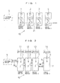
FIG. 1 is a configuration diagram of a first embodiment showing only
a portion relating to setting of IDs in an electronic device system shown in
FIG. 2;
FIG. 2 is a schematic diagram showing an embodiment of an
electronic device system according to the invention;
FIG. 3 is an explanatory diagram showing the outline of the ID setting
in the electronic device system shown in FIG. 1;
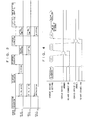
FIG. 4 is a time chart showing details of actions of the ID setting;
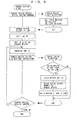
FIG. 5 is a flowchart similarly showing actions of a parent device and
a child device at the time of ID automatic setting;
FIG. 6 is a configuration diagram of a second embodiment showing
only a portion relating to setting of IDs in the electronic device system shown
in FIG. 2;
FIG. 7 is a time chart showing actions of the ID setting according to
the second embodiment;
FIG. 8 is a flowchart similarly showing actions of a parent device and
a child device at the time of ID automatic setting;
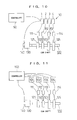
FIG. 9 is a schematic diagram showing another embodiment of the
electronic device system according to the invention;
FIG. 10 is a configuration diagram showing an example when the
electronic device system according to the invention is used to measure the
shapes of cams of a cam shaft; and
FIG. 11 is a configuration diagram showing an example of a
conventional electronic device system for measuring the shapes of cams of a
conventional cam shaft.
BEST MODE FOR CARRYING OUT THE INVENTION
To describe the invention in more detail, preferred embodiments of
the invention will be described with reference to the accompanying drawings.
FIG. 2 is a schematic diagram showing an embodiment of an
electronic device system according to the invention which is composed of
four electronic device units 1 to 4. The electronic device unit 1 out of them
is a parent device which includes a female connector (an external device
interface) 6 for connecting to an external device 5 having a data processing
function and a female connector (a downstream device interface) 7 for
connecting to the other electronic device units (child devices), and thus has a
function of transmitting/receiving data to/from the external device 5.
The electronic device units 2 to 4 are the child devices each including
two connectors for connecting to the other electronic device units. In this
example, a male connector (an upstream device interface) 8 is provided on
one of two parallel faces of a thin rectangular parallelepiped case having a
larger area than that of the other faces, and a female connector (a downstream
device interface) 7 is provided on the other of the two parallel faces.
To the electronic device unit 1 being the parent device, the electronic
device units 2 to 4 being child devices are mechanically and electrically
connected in series and in sequence by fitting between the connectors 7 and 8,
thus constituting an electronic device system 10.
For use of the electronic device system 10, the external device such as
a personal computer or a controller is connected to the female connector 6 of
the electronic device unit 1 being the parent device using an RS-232C
interface cable 16, and detectors 11 to 14 are connected to connectors 9 for
the detectors provided on side faces of the electronic device units 1 to 4.
The detectors 11 to 14 can be detectors for displacement measurement similar
to the detectors 111 to 114 shown in the above-described FIG. 11, and other
various detectors can be connected, such as for voltage, resistance,
temperature, pressure, amount of light, volume, and distortion amount. The
electronic device units 1 to 4 include circuits and so on corresponding to the
detectors to be connected thereto, and different kinds of detectors may be
connected to the electronic device units, respectively.
The electronic device unit 1 being the parent device out of the
electronic device units 1 to 4 constituting the electronic device system 10 can
directly transmit/receive data to/from the external device 5, whereas the
electronic device units 2 to 4 being child devices can transmit/receive data
to/from the external device 5 via the parent device or via the parent device
and the other child devices.
It should be noted that power is fed from the external device 5 to the
electronic device unit 1 being the parent device via a power cable and then fed
also to all of the electronic device units 2 to 4 being child devices via power
terminals in the connectors 7 and 8 and power lines within the child devices.
Incidentally, in order for the external device 5 to transmit/receive data
to/from the electronic device units 1 to 4, it is necessary to set identification
codes (IDs) in the electronic device units 1 to 4 respectively so as to be able to
identify to which electronic device unit the external device 5 transmits data or
from which electronic device unit the external device 5 has received data.
A configuration for automatically setting the IDs and a function
thereof will be described below.
FIG. 1 is a configuration diagram of a first embodiment showing only
a part relating to the setting of the IDs in the above-described electronic
device system 10.
All of the electronic device units 1 to 4 being the parent device and the
child devices each incorporate a microcomputer (hereinafter, abbreviated as a
"CPU") 20, which is composed of a CPU, a ROM and a RAM being
memories, and so on. All of the electronic device units 1 to 4 are also
connected to one another by an RS-485 interface line 21 via the respective
connectors, and the interface line 21 is connected to the respective CPUs 20.
The electronic device units 1 to 4 include switches (actually two circuits) 22
which open and close the interface line 21, and opening/closing of each of the
switches 22 is controlled by the CPU 20.
ID setting actions in the electronic device system 10 will be described
with FIG. 3 to FIG. 5. In these drawings and the following description, the
electronic device unit 1 is called as a "parent device", and the electronic
device units 2 to 4 are called as a "child device 1," a "child device 2," and a
"child device 3" as also shown in FIG. 1.
FIG. 3 shows the outline of the ID setting, and FIG. 4 is a time chart
showing details of the setting, with the child device 3 being omitted in FIG. 4.
As shown in these drawings, the parent device first outputs an
initialization instruction (an initialization command) to all of the child devices
via the RS-485 interface line 21 shown in FIG. 1.
However, the child devices have automatically performed
initialization processing when power is turned on, thereby turning off the
switches 22 (bringing the RS-485 connection to Low). For this reason, when
the processing of the ID automatic setting is started when the electronic
device system 10 is fed with power from the external device 5, the
initialization instruction from the parent device does not need to be
transmitted to the child devices. The case where the initialization instruction
(the initialization command) from the parent device becomes effective is only
when the ID is set again after setting once. In this case, the switches 22 of
all of the child devices are on (the RS-485 connection is at High), so that the
initialization instruction is transmitted to all of the child devices. This
initializes all of the child devices, and the CPUs 20 shown in FIG. 1 turn off
the switches 22 (bring the RS-485 connection to Low).
Though not shown in FIG. 3 and FIG. 4, the CPU 20 of the parent
device generates a first ID "1" in this event and sets it as its own ID (stores it
in the RAM of the CPU 20). The CPU 20 then turns on its own switch 22
(brings the RS-485 connection to High).
Thereafter, the parent device generates a next ID "2" and outputs an
ID setting instruction. The child device 1 receives the instruction and sets
"2" as its own ID, and outputs an answer of setting completion to the parent
device and turns on its own switch 22 (brings the RS-485 connection to
High).
Subsequently, the parent device generates an ID "3" and outputs an ID
setting instruction. The child device 2 receives the instruction and sets "3"
as its own ID, and outputs an answer of setting completion to the parent
device and turns on its own switch 22 (brings the RS-485 connection to
High).
Subsequently, the parent device generates an ID "4" and outputs an ID
setting instruction. The child device 3 receives the instruction and sets "4"
as its own ID, and outputs an answer of setting completion to the parent
device and turns on its own switch 22 (brings the RS-485 connection to High),
but there is no child device connected next. In the case of FIG. 4, since the
child device 3 is not connected, there is no answer of setting completion
within a predetermined period to the setting instruction of the ID "4" from the
parent device, and the setting is completed because time is up.
In the case of FIG. 3, since there is an answer from the child device 3,
the parent device generates a next ID "5" and outputs an ID setting instruction,
but since no child device is connected next, there is no answer of setting
completion within a predetermined period, and the setting is completed
because time is up.
In the above manner, the parent device successively generates IDs for
the electronic device units, and the electronic device units 1 to 4 automatically
set the successively generated IDs "1 to 4" as their own IDs respectively in
the order of the child devices connected in series to the parent device,
beginning from the parent device.
Actions of the parent device and the child devices at the time of ID
automatic setting will be described in detail with a flowchart shown in FIG. 5.
The ID automatic setting is performed, for example, every time power is
turned on.
When starting this processing, the parent device first outputs an
initialization command. All of the child devices are initialized when power
is turned on, and the CPUs 20 in the electronic device units 2 to 4 being child
devices shown in FIG. 1 turn off their own switches 22 (bring the RS-485
connection to Low), and otherwise they are initialized according to the
initialization command from the parent device. After completion of the
initialization, the CPU 20 of the parent device sets "1" for the first ID and sets
it as its own ID, and then turns on the switch 22 of the parent device (the
electronic device unit 1) shown in FIG. 1 (brings the RS-485 connection to
High).
Thereafter, the parent device increases one ID as "2" and outputs an
ID setting instruction to the RS-485 interface line 21.
Then, only the child device 1 (the electronic device unit 2) connected
with the RS-485 interface line 21 receives the instruction and determines
whether or not its own RS-485 connection is Low (the switch 22 in FIG. 1 is
off), and if the determination is NO, the child device 1 ends the processing as
it is. However, the determination is YES in this case, and therefore the child
device sets the ID "2" as its own ID and outputs an answer of setting
completion to the parent device, and then turns on its own switch 22 to bring
the RS-485 connection to High.
Upon receipt of the answer from the child device, the parent device
(the electronic device unit 1) increases again one ID as "3" and outputs an ID
setting instruction.
Since connection of the RS-485 interface line 21 from the parent
device to the child device 2 is established this time, the child device 1 (the
electronic device unit 2) and the child device 2 (the electronic device unit 3)
receive the instruction, but the child device 1 performs nothing to an end
because its RS-485 connection is High which means its ID has already been
set. The child device 2 sets the received ID "3" as its own ID because its
RS-485 connection is Low, and outputs an answer of setting completion to the
parent device and then turns on its own switch 22 to bring its RS-485
connection to High.
Upon receipt of the answer, the parent device (the electronic device
unit 1) increases again one ID as "4" and outputs an ID setting instruction.
In the above manner, the parent device increases one ID and outputs
an ID setting instruction every time it receives an answer from the child
device. The child device with its switch 22 being off and its RS-485
connection being Low out of the child devices which have received the
instruction, sets the ID as its own ID and outputs an answer to the parent
device, and then turns on its switch 22 to bring its RS-485 connection to High.
This action is repeated so that IDs are set in the parent device and all of the
child devices connected thereto, and if the parent device cannot receive an
answer of setting completion from the child device within a predetermined
period after the parent device outputs an ID setting instruction, the processing
is ended.
Also when four or more child devices are connected, this action is
repeated until after IDs are set in all of the child devices in a similar manner.
These kinds of processing are performed by the CPU 20 in the parent
device (the electronic device unit 1) and the CPUs 20 in the child devices (the
electronic device units 2 to 4) shown in FIG. 1.
More specifically, in this embodiment, the CPU 20 in the parent
device functions as means for successively generating identification codes
(IDs) for the electronic device units 1 to 4, and the CPUs 20 in the electronic
device units 1 to 4 function as means for automatically setting the
successively generated IDs as their own IDs in the order of series connection
to the parent device.
Further, the CPU 20, together with the switch 22, in each of the
electronic device units 1 to 4 sets as its own ID the ID generated by the
electronic device unit 1 being the parent device, and thereafter turns on its
own switch 22 to bring the RS-485 connection to High, thereby functioning to
report that it has already set its ID to the electronic device unit connected
next.
Further, the CPU 20 of the electronic device unit 1 being the parent
device also functions as means for determining that all of the child devices
have completed setting of the IDs when the CPU 20 issues an ID setting
instruction to the child device and then receives no answer of setting
completion from the child device within a predetermined period previously
set.
Next, a configuration of a second embodiment of a part relating to the
setting of the IDs in the electronic device system 10 shown in FIG. 2 and the
ID automatic setting action thereby will be described with reference to FIG. 6
to FIG. 8.
FIG. 6 is a diagram showing a configuration of a part relating to the
ID setting in which all of electronic device units 1 to 4 connected in series and
constituting an electronic device system 10 are commonly connected in a
skewered manner by an RS-485 interface line 21 so that CPUs 20 of the
electronic device units 1 to 4 can mutually transmit/receive signals over the
RS-485 interface line 21. Further, DL-INs and DL-OUTs of the CPUs 20
are connected in series.
In the second embodiment, the outline of the ID setting is similar to
that of the first embodiment shown in FIG. 3. The second embodiment is
different from the first embodiment only in that since all of the electronic
device units are connected over the RS-485 interface line 21 at all times, the
parent device can forcibly output an initialization instruction to all of the child
devices via the RS-485 interface line 21; that the CPU 20 of the electronic
device unit in which the ID has been set brings the DL-OUT to Low to report
that the unit has already set its ID to the electronic device unit connected next;
and that the child device determines whether to set as its own ID the ID
generated by the parent device, depending on states of the DL-IN and the DL-OUT.
Therefore, a time chart in FIG. 7 and a flowchart in FIG. 8 are almost
the same as those in FIG. 4 and FIG. 5 of the first embodiment except that
when all of the child devices are initialized according to the initialization
instruction (the initialization command) from the parent device, the DL-OUTs
of their CPUs 20 are brought to High, and thereafter when the IDs
successively generated by the parent device are set, their DL-OUTs are
brought to Low.
Further, the ID setting instruction from the parent device is outputted
to all of the connected child devices, which is different only in that only the
child device with the DL-OUT being High and the DL-IN being Low sets its
ID and outputs an answer of setting completion to the parent device and then
performs processing of bringing the DL-OUT to Low.
The processing of the ID automatic setting is performed by the CPUs
20 in the electronic device units 1 to 4 shown in FIG. 6.
It has been described that the processing of the ID automatic setting is
performed when power is turned on, however the processing could be
performed by a key operation to the external device or the parent device. In
addition, the processing may be performed when a specific condition such as
error processing is established. Alternatively, it is also suitable to allow the
setting to be also performed manually through a key operation on the external
device or the electronic device units, or to allow either automatic setting or
manual setting to be set using a DIP switch or a parameter.
The electronic device units 1 to 4 composed of the parent device and
the plurality of child devices are connected in series and IDs of the electronic
device units are set as described above, whereby the external device
connected to the parent device (the electronic device unit 1) over an RS-232C
interface cable for serial communication can determine the number of the
connected electronic device units and start-up states and the presence or
absence of failure of the units; request data, issue a zero-reset instruction, and
set parameters with a specific electronic device unit being designated; and
instruct a plurality of electronic device units to perform adding and
subtracting calculation of measurement data.
For example, when five child devices are coupled to one parent device,
that is, when six electronic device units, in total, are coupled (mechanically
and electrically connected) to constitute the electronic device system, the ID
of the parent device is "1" and the IDs of the child devices are "2 to 6" in the
order from the closest to the farthest from the parent device. The external
device connected only to the parent device can designate a desired electronic
device unit by its ID. For example, when data of two devices, the parent
device and the child device farthest from the parent device, among all of the
electronic device units are required, the external device only needs to make a
request for data from the parent device with ID = 1 and ID = 6 being
designated.
Further, even if the connection order of the electronic device units
constituting the electronic device system is changed, if part of the electronic
device units are replaced with electronic device units having other functions,
or if the number of the electronic device units to be connected is increased or
decreased, there occurs no trouble because the IDs of the electronic device
units after the change are automatically set again when power in turned on or
the like.
It should be noted that the above-described embodiment shows an
example in which the electronic device units constituting the electronic device
system can be directly connected by the connectors to be mechanically and
electrically connected together for use, thereby eliminating the necessity of
connection cable between the electronic device units to realize an electronic
device system which is compact in size and easy to use. Depending on
applications, however, all or part of the electronic device units may be
electrically connected in series via the connection cable. Any number of
electronic device units being child devices may be connected in series.
Next, another embodiment of the electronic device system according
to the invention will be described using FIG. 9. Also in FIG. 9, the same
numbers are assigned to portions corresponding to those in FIG. 1 and FIG. 6
of the above-described embodiment, and description thereof is omitted.
An electronic device system 10' of this embodiment is different from
the electronic device system 10 of above-described embodiment in that all of
electronic devices 1 to 4 connected in series to constitute the electronic device
system 10' have the same configuration.
The electronic device system 10' is also different in that each of the
electronic device units 1 to 4 includes a connector 26 connectable to an
external device and the other electronic device units, a connector 27 for
connecting to the other electronic device units, and a control unit 20'
including a microcomputer similar to the microcomputer (abbreviated as a
CPU) 20 in the above-described embodiment. The CPU 20 shown in the
above-described FIG. 1 and FIG. 6, however, also has input/output control
circuits such as the RS-232C, RS-485, and so on actually, and therefore the
CPU 20 and the control unit 20' are substantially equivalent.
Then, the connector 26 and the connector 27 are connected by an RS-485
interface line 21, and the interface line 21 is also connected to the control
units 20'. Further, a signal line between the electronic device units including
a DL-IN similar to that of the embodiment shown in FIG. 6 is connected
between the control unit 20' and the connector 26, and a signal line between
the electronic device units including a DL-OUT similar to that of the
embodiment shown in FIG. 6 is connected between the control unit 20' and
the connector 27.
Incidentally, in this embodiment, a connection pin for the RS-232C to
be connected to the control unit 20' is also provided in the connector 26 in
each of the electronic device units 1 to 4, so as to be connectable with the
external device such as a personal computer or a controller over an RS-232C
interface cable 16.
The plurality of electronic device units 1 to 4 are connected, by direct
fitting between the connectors 26 and 27 or via the interface cable, to thereby
be successively connected in series to constitute the electronic device system
10'.
The control unit 20' in each of the electronic device units 1 to 4
functions as a recognition means by recognizing itself to be the parent device
because there is no electronic device unit connected in front of the unit itself
and there is another electronic device unit connected behind the unit itself, or
recognizing itself to be the child device because there is another electronic
device unit connected in front of the unit itself.
Further, each of the control units 20' also has a function of, when
recognizing itself to be the parent device by the recognizing means that is its
own function, successively generating identification codes (IDs) for the
electronic device units 1 to 4, or a function of, when recognizing itself to be
the child device by the recognizing means, automatically setting as its own
identification code one of the IDs successively generated from the electronic
device unit, which has recognized itself to be the parent device (the electronic
device unit 1 in the example of FIG. 9), in the order of series connection
beginning from the electronic device unit which has recognized itself to be the
parent device.
Each of the control units 20' also has a function of, when recognizing
itself to be the parent device, automatically setting (storing in its memory), as
an identification code of the parent device, the first identification code which
the control unit 20' itself has generated.
Furthermore, each of the control units 20' can recognize itself to be the
last electronic device unit (the electronic device unit 4 in the example in FIG.
9) because none of the other above-described electronic device units is
connected behind the unit itself, and transmit the fact to the electronic device
unit which has recognized itself to be the parent device (the electronic device
unit 1 in the example in FIG. 9).
Further, each of the control units 20', when recognizing itself as the
parent device, can determine that all of the other electronic device units have
completed setting of the IDs when it issues an ID setting instruction to the
other electronic device units and then receives no answer of setting
completion from the other electronic device units within a predetermined
period previously set.
The number of the electronic device units constituting the electronic
device system 10' is not limited to four, but any number, but more than one,
of electronic device units having exactly the same configuration can be
connected in series to constituted the electronic device system 10'.
FIG. 10 shows a configuration example when the electronic device
system according to the invention to measure the shapes of cams of a cam
shaft in a similar manner as that of the conventional example shown in FIG.
11, in which the same numbers are assigned to the same portions as those in
FIG. 11.
It is only required that a controller 50 is connected only to an
electronic device unit 1 being the parent device of an electronic device system
10 or 10' using an RS-232C interface cable, and an output signal line of a
rotation pulse of an encoder 140 is connected to the parent device. Detectors
111 to 114 for displacement measurement, which are the same as those shown
in above-described FIG. 11, are connected to electronic device units 1 to 4
constituting the electronic device system 10 or 10'. This configuration
reduces the load on the controller 50 as well as substantially decreases the
number of connection lines.
INDUSTRIAL APPLICABILITY
As has been described, the electronic device system according to the
invention can automatically set identification codes (IDs) in a plurality of
electronic device units connected in series, thus eliminating a troublesome ID
setting operation by hand so that occurrence of ID setting mistakes is
prevented and the ID is automatically set again when power is turned on or
the like even when the system is rearranged, bringing about no problem.
Consequently, the invention can be used in various electronic device
systems composed of a plurality of electronic device units connected in series,
for example, an electronic device system for measuring the plate thickness or
shape, in which IDs can be automatically and surely set in the electronic
device units.