EP1553650A1 - Fuel cell - Google Patents
Fuel cell Download PDFInfo
- Publication number
- EP1553650A1 EP1553650A1 EP03764118A EP03764118A EP1553650A1 EP 1553650 A1 EP1553650 A1 EP 1553650A1 EP 03764118 A EP03764118 A EP 03764118A EP 03764118 A EP03764118 A EP 03764118A EP 1553650 A1 EP1553650 A1 EP 1553650A1
- Authority
- EP
- European Patent Office
- Prior art keywords
- fuel cell
- diffusion layer
- tension
- separator
- imposed
- Prior art date
- Legal status (The legal status is an assumption and is not a legal conclusion. Google has not performed a legal analysis and makes no representation as to the accuracy of the status listed.)
- Withdrawn
Links
Images

Classifications
-
- H—ELECTRICITY
- H01—ELECTRIC ELEMENTS
- H01M—PROCESSES OR MEANS, e.g. BATTERIES, FOR THE DIRECT CONVERSION OF CHEMICAL ENERGY INTO ELECTRICAL ENERGY
- H01M8/00—Fuel cells; Manufacture thereof
- H01M8/24—Grouping of fuel cells, e.g. stacking of fuel cells
-
- H—ELECTRICITY
- H01—ELECTRIC ELEMENTS
- H01M—PROCESSES OR MEANS, e.g. BATTERIES, FOR THE DIRECT CONVERSION OF CHEMICAL ENERGY INTO ELECTRICAL ENERGY
- H01M4/00—Electrodes
- H01M4/86—Inert electrodes with catalytic activity, e.g. for fuel cells
- H01M4/8605—Porous electrodes
-
- H—ELECTRICITY
- H01—ELECTRIC ELEMENTS
- H01M—PROCESSES OR MEANS, e.g. BATTERIES, FOR THE DIRECT CONVERSION OF CHEMICAL ENERGY INTO ELECTRICAL ENERGY
- H01M8/00—Fuel cells; Manufacture thereof
- H01M8/02—Details
-
- H—ELECTRICITY
- H01—ELECTRIC ELEMENTS
- H01M—PROCESSES OR MEANS, e.g. BATTERIES, FOR THE DIRECT CONVERSION OF CHEMICAL ENERGY INTO ELECTRICAL ENERGY
- H01M8/00—Fuel cells; Manufacture thereof
- H01M8/02—Details
- H01M8/0202—Collectors; Separators, e.g. bipolar separators; Interconnectors
- H01M8/023—Porous and characterised by the material
-
- H—ELECTRICITY
- H01—ELECTRIC ELEMENTS
- H01M—PROCESSES OR MEANS, e.g. BATTERIES, FOR THE DIRECT CONVERSION OF CHEMICAL ENERGY INTO ELECTRICAL ENERGY
- H01M8/00—Fuel cells; Manufacture thereof
- H01M8/02—Details
- H01M8/0202—Collectors; Separators, e.g. bipolar separators; Interconnectors
- H01M8/0258—Collectors; Separators, e.g. bipolar separators; Interconnectors characterised by the configuration of channels, e.g. by the flow field of the reactant or coolant
-
- H—ELECTRICITY
- H01—ELECTRIC ELEMENTS
- H01M—PROCESSES OR MEANS, e.g. BATTERIES, FOR THE DIRECT CONVERSION OF CHEMICAL ENERGY INTO ELECTRICAL ENERGY
- H01M8/00—Fuel cells; Manufacture thereof
- H01M8/02—Details
- H01M8/0202—Collectors; Separators, e.g. bipolar separators; Interconnectors
- H01M8/0267—Collectors; Separators, e.g. bipolar separators; Interconnectors having heating or cooling means, e.g. heaters or coolant flow channels
-
- H—ELECTRICITY
- H01—ELECTRIC ELEMENTS
- H01M—PROCESSES OR MEANS, e.g. BATTERIES, FOR THE DIRECT CONVERSION OF CHEMICAL ENERGY INTO ELECTRICAL ENERGY
- H01M8/00—Fuel cells; Manufacture thereof
- H01M8/02—Details
- H01M8/0271—Sealing or supporting means around electrodes, matrices or membranes
-
- H—ELECTRICITY
- H01—ELECTRIC ELEMENTS
- H01M—PROCESSES OR MEANS, e.g. BATTERIES, FOR THE DIRECT CONVERSION OF CHEMICAL ENERGY INTO ELECTRICAL ENERGY
- H01M8/00—Fuel cells; Manufacture thereof
- H01M8/02—Details
- H01M8/0271—Sealing or supporting means around electrodes, matrices or membranes
- H01M8/0273—Sealing or supporting means around electrodes, matrices or membranes with sealing or supporting means in the form of a frame
-
- H—ELECTRICITY
- H01—ELECTRIC ELEMENTS
- H01M—PROCESSES OR MEANS, e.g. BATTERIES, FOR THE DIRECT CONVERSION OF CHEMICAL ENERGY INTO ELECTRICAL ENERGY
- H01M8/00—Fuel cells; Manufacture thereof
- H01M8/04—Auxiliary arrangements, e.g. for control of pressure or for circulation of fluids
- H01M8/04223—Auxiliary arrangements, e.g. for control of pressure or for circulation of fluids during start-up or shut-down; Depolarisation or activation, e.g. purging; Means for short-circuiting defective fuel cells
- H01M8/04225—Auxiliary arrangements, e.g. for control of pressure or for circulation of fluids during start-up or shut-down; Depolarisation or activation, e.g. purging; Means for short-circuiting defective fuel cells during start-up
-
- H—ELECTRICITY
- H01—ELECTRIC ELEMENTS
- H01M—PROCESSES OR MEANS, e.g. BATTERIES, FOR THE DIRECT CONVERSION OF CHEMICAL ENERGY INTO ELECTRICAL ENERGY
- H01M8/00—Fuel cells; Manufacture thereof
- H01M8/04—Auxiliary arrangements, e.g. for control of pressure or for circulation of fluids
- H01M8/04298—Processes for controlling fuel cells or fuel cell systems
- H01M8/043—Processes for controlling fuel cells or fuel cell systems applied during specific periods
- H01M8/04302—Processes for controlling fuel cells or fuel cell systems applied during specific periods applied during start-up
-
- H—ELECTRICITY
- H01—ELECTRIC ELEMENTS
- H01M—PROCESSES OR MEANS, e.g. BATTERIES, FOR THE DIRECT CONVERSION OF CHEMICAL ENERGY INTO ELECTRICAL ENERGY
- H01M8/00—Fuel cells; Manufacture thereof
- H01M8/24—Grouping of fuel cells, e.g. stacking of fuel cells
- H01M8/241—Grouping of fuel cells, e.g. stacking of fuel cells with solid or matrix-supported electrolytes
- H01M8/242—Grouping of fuel cells, e.g. stacking of fuel cells with solid or matrix-supported electrolytes comprising framed electrodes or intermediary frame-like gaskets
-
- H—ELECTRICITY
- H01—ELECTRIC ELEMENTS
- H01M—PROCESSES OR MEANS, e.g. BATTERIES, FOR THE DIRECT CONVERSION OF CHEMICAL ENERGY INTO ELECTRICAL ENERGY
- H01M8/00—Fuel cells; Manufacture thereof
- H01M8/02—Details
- H01M8/0202—Collectors; Separators, e.g. bipolar separators; Interconnectors
- H01M8/023—Porous and characterised by the material
- H01M8/0234—Carbonaceous material
-
- H—ELECTRICITY
- H01—ELECTRIC ELEMENTS
- H01M—PROCESSES OR MEANS, e.g. BATTERIES, FOR THE DIRECT CONVERSION OF CHEMICAL ENERGY INTO ELECTRICAL ENERGY
- H01M8/00—Fuel cells; Manufacture thereof
- H01M8/02—Details
- H01M8/0202—Collectors; Separators, e.g. bipolar separators; Interconnectors
- H01M8/0247—Collectors; Separators, e.g. bipolar separators; Interconnectors characterised by the form
-
- H—ELECTRICITY
- H01—ELECTRIC ELEMENTS
- H01M—PROCESSES OR MEANS, e.g. BATTERIES, FOR THE DIRECT CONVERSION OF CHEMICAL ENERGY INTO ELECTRICAL ENERGY
- H01M8/00—Fuel cells; Manufacture thereof
- H01M8/10—Fuel cells with solid electrolytes
- H01M8/1007—Fuel cells with solid electrolytes with both reactants being gaseous or vaporised
-
- Y—GENERAL TAGGING OF NEW TECHNOLOGICAL DEVELOPMENTS; GENERAL TAGGING OF CROSS-SECTIONAL TECHNOLOGIES SPANNING OVER SEVERAL SECTIONS OF THE IPC; TECHNICAL SUBJECTS COVERED BY FORMER USPC CROSS-REFERENCE ART COLLECTIONS [XRACs] AND DIGESTS
- Y02—TECHNOLOGIES OR APPLICATIONS FOR MITIGATION OR ADAPTATION AGAINST CLIMATE CHANGE
- Y02E—REDUCTION OF GREENHOUSE GAS [GHG] EMISSIONS, RELATED TO ENERGY GENERATION, TRANSMISSION OR DISTRIBUTION
- Y02E60/00—Enabling technologies; Technologies with a potential or indirect contribution to GHG emissions mitigation
- Y02E60/30—Hydrogen technology
- Y02E60/50—Fuel cells
Definitions
- the present invention relates to a fuel cell. More particularly, the present invention relates to a diffusion electrode of a polymer electrolyte fuel cell.
- a polymer electrolyte fuel cell includes a membrane-electrode assembly (MEA) and a separator. At least one layer of the fuel cell forms a module and a number of modules are piled.
- the MEA includes an electrolyte membrane, a first electrode (an anode) including a catalyst layer and a diffusion layer disposed on one side of the electrolyte membrane, and a second electrode (a cathode) including a catalyst layer and a diffusion layer disposed on the other side of the electrolyte membrane.
- a fuel gas passage for supplying fuel gas (e.g., hydrogen) to the anode and an oxidant gas passage for supplying oxygen gas (e.g., oxygen, usually, air) to the cathode are formed.
- a coolant (e.g., water) passage is formed per one fuel cell or a plurality of fuel cells in the separators.
- the separator constructs an electron current passage between adjacent fuel cells.
- Electrical terminals, electrical insulators, and end plates are disposed at opposite ends of the pile of modules.
- the pile of modules are tightened between the opposite end plates in a fuel cell stacking direction and the opposite end plates are coupled to a fastening member (for example, a tension plate) extending in the fuel cell stacking direction outside the pile of fuel cells, by bolts and nuts to form a stack of fuel cells.
- a fastening member for example, a tension plate
- hydrogen is changed to positively charged hydrogen ions (i.e., protons) and electrons.
- the hydrogen ions move through the electrolyte membrane to the cathode where the hydrogen ions react with oxygen supplied and electrons (which are generated at an anode of the adjacent MEA and move to the cathode of the instant MEA through a separator, or which are generated at an anode of a fuel cell located at a first end of the pile of fuel cells and move to a cathode of a fuel cell located at a second, opposite end of the pile of fuel cells through an external electrical circuit) to form water as follows:
- the diffusion layer is made from at least one layer of carbon cloth or carbon paper.
- the diffusion layer made from layered of carbon cloths or carbon papers is low in rigidity, and the electrolyte membrane and the catalyst layer are also low in rigidity, a rib (a convex of convex and concave portions) of the gas passage of the separator intrudes on or pushes into the diffusion layer (see, e.g., region A of FIG. 6), resulting in a bending deformation of the diffusion layer and the electrolyte membrane.
- durability of portions of the diffusion layer and the electrolyte membrane where corners (shoulders) of the ribs of the separator contact the diffusion layer decreases, accompanied by a decrease in durability of the fuel cell.
- the diffusion layer In order to increase a rigidity of the diffusion layer thereby preventing the diffusion layer from pushing into the membrane due to pressure from the separator, it might be effective to make the diffusion layer from a wire netting or a composite carbon paper (a composite of carbon and phenol resin.
- An object of the present invention is to provide a fuel cell which can prevent a rib of a separator from deforming a membrane whereby gas passability of a diffusion layer can be kept well.
- a fuel cell according to the present invention to achieve the above object is as follows:
- a magnitude of the tension is adjustable according to the fuel cell operating condition, by adjusting the tension to a small magnitude during a start-up of the fuel cell from a low temperature, the electric conductivity between the diffusion layer and the membrane can be decreased thereby increasing heat generation due to an increase in a contact resistance, and by adjusting the tension to a large magnitude during a constant fuel cell operation, the electric conductivity between the diffusion layer and the membrane can be increased.
- FIG. 6 illustrates a fuel cell of a comparison or a conventional fuel cell
- the fuel cell according to the present invention is a polymer electrolyte fuel cell (PEFC) 10.
- the fuel cell 10 is mounted to, for example, a vehicle. However, the fuel cell 10 may be used in an environment other than a vehicle.
- the polymer electrolyte fuel cell 10 includes a membrane-electrode assembly (MEA) and a separator 18 layered to the MEA. At least one fuel cell forms a fuel cell module 19, and a plurality of fuel cell modules are piled.
- MEA membrane-electrode assembly
- the MEA includes an electrolyte membrane 11 made from an ion exchange membrane, a first diffusion electrode 14 (anode) including a catalyst layer 12 and a diffusion layer 13 disposed on one side of the electrolyte membrane, and a second diffusion electrode 17 (cathode) including a catalyst layer 15 and a diffusion layer 16 disposed on the other side of the electrolyte membrane.
- terminal plates 20 Electrical terminals (terminal plates) 20, electrical insulators 21, and end plates 22 are disposed at opposite ends of the pile of fuel cell modules.
- the end plates are coupled by bolts 25 to fastening members (for example, tension plates 24) which extend in a longitudinal direction (fuel cell module piling direction) of the pile of fuel cell modules outside the pile of the fuel cell modules, and the fuel cell modules are tightened in the longitudinal direction of the pile of fuel cell modules and, together with the members 20, 21, 22 and 24, construct a fuel cell stack 23.
- fastening members for example, tension plates 24
- a fuel gas passage 26 for supplying fuel gas (e.g., hydrogen) to the anode 12 is formed in an anode-side separator of a pair of separators opposing each other via the MEA.
- a fuel gas passage 27 for supplying oxidant gas (e.g., oxygen, usually, air) to the cathode 14 is formed in a cathode-side separator of the pair of separators opposing each other via the MEA.
- oxidant gas passage 27 for supplying oxidant gas (e.g., oxygen, usually, air) to the cathode 14 is formed in the separator 18.
- a coolant passage for cooling the fuel cell is formed each fuel cell or each plurality of fuel cells.
- the coolant passage is formed in a surface of the separator 18 opposite an MEA contacting surface of the separator.
- the separator 18 separates the coolant from the fuel gas or the oxidant gas, or separates the fuel gas from the oxidant gas.
- the separator 18 operates as
- the separator 18 can be non-conductive.
- the diffusion layer 13 is formed in a sheet having a small thickness like a membrane (a thin sheet).
- the catalyst layer 12 can be coated on an MEA opposing surface of the diffusion layer 13 so that the catalyst layer 12 and the diffusion layer 13 form the thin sheet, or the catalyst layer 12 can be coated on the membrane 11 so that the diffusion layer 13 is a layer separate from the catalyst layer 12.
- the diffusion layer 16 is formed in a sheet having a small thickness like a membrane (a thin sheet).
- the catalyst layer 15 can be coated on an MEA opposing surface of the diffusion layer 16 so that the catalyst layer 15 and the diffusion layer 16 form the thin sheet, or the catalyst layer 15 can be coated on the membrane 11 so that the diffusion layer 16 is a layer separate from the catalyst layer 15.
- a tension (tension force) F of a specified magnitude directed in an in-plane direction of the sheet (a direction parallel to a major surface of the sheet) is applied in a fuel cell assembled and tightened as described above.
- the fuel cell stack is tightened keeping the state where the tension F acts in the diffusion layer 13, 16.
- This condition that "the fuel cell stack is tightened keeping the state where the tension F acts in the diffusion layer 13, 16" includes a case where, in keeping the state where the tension F is imposed on the diffusion layer 13, 16, the diffusion layer 13, 16 is fixed to a separator 18 by an adhesive, and then the separator fixed with the diffusion layer 13, 16 and the membrane 11 or the MEA are layered and are tightened.
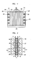
- FIG. 5 illustrates a state where the fuel cell modules 19 are layered in a longitudinal direction of a pile of fuel cell modules and a tightening load is not yet imposed on the pile of fuel cell modules.
- FIG. 2 illustrates a state where a tightening load is imposed on the pile of fuel cell modules.
- FIG. 2 illustrates a portion of one fuel cell module in an enlarged cross section.
- the separator 18 can be electrically non-conductive.
- the tension is imposed on the diffusion layer 13, 16 in a direction perpendicular to the gas passage 26, 27 formed in the separator 18 which the diffusion layer 13, 16 contacts.
- the tension F directed in an up-and-down direction of FIG. 3 is imposed on the diffusion layer 13, 16.
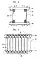
- FIGs. 4 and 5 One example of a method of imposing the tension on the diffusion layer 13, 16 is illustrated in FIGs. 4 and 5.
- opposite ends of threads (e.g., carbon threads) 28 constituting a textile of the sheet of diffusion layer 13, 16 are fixed to (e.g., bound to or bonded to) frames 29 (an upper frame and a lower frame) disposed outside the fuel cell, and by moving the frames 29 in a direction away from each other by using a support pole 30 to separate the frames 29 so that a tension is imposed on the diffusion layer 13, 16.
- threads e.g., carbon threads
- a right-hand thread is formed in one end portion of the support pole and a lefthand thread is formed in the other end portion of the support pole, and by rotating the support pole about an axis of the support pole, the frames 29 are moved in a direction away from each other or closer to each other.
- the frames are moved apart so that the tension is imposed on the diffusion layer 13, 16.
- knots or expanded portions 32 are formed in opposite ends of some or all of the threads 28. Then, letting portions of the threads other than the knots or expanded portions extend through the slits or holes formed in the frames 29 and letting the knots or expanded portions 32 engage outboard surfaces of the frames 29, the threads 28 can be fixed to the frames 29 and extend in a direction of the applied tension.
- the tension imposed on the diffusion layer 13, 16 is of such a magnitude as to prevent a portion of the sheet positioned corresponding to a gas passage of a separator from being deformed, that is, the tension prevents the ribs of the gas passage of the separator 18 from pushing into the membrane 11, when the fuel cell is tightened.
- the tension F imposed on the diffusion layer 13, 16 may be adjustable according to an operating condition of the fuel cell. It is easy to adjust the tension F in the case where the threads 28 are bound to the frames 29.
- the tension F is adjusted according to the fuel cell operating condition, it is preferable that the tension is adjusted to a first, small magnitude during a start-up of the fuel cell from a low temperature and the tension is adjusted to a second, large magnitude larger than the first magnitude during a constant operation of the fuel cell.
- FIG. 6 illustrates a conventional state where a tension is not imposed on a diffusion layer.
- FIG. 2 illustrates a state according to the present invention where the tension is imposed on the diffusion layer.
- the state according to the present invention becomes close to the state of FIG. 6.
- a contact pressure between the diffusion layer 13, 16 and a rib of the separator 18 is small so that the electric conductivity of the electrode diffusion layer 13, 16 decreases whereby heat generation is promoted, and the electrode diffusion layer 13, 16 is deformed in a direction away from the membrane 11 at a portion where the electrode diffusion layer 13, 16 is not pressed by the separator rib (see, e.g., region A of FIG. 6) and a heat is collected in that portion.
- the fuel cell is smoothly activated during start-up of the fuel cell from a low temperature and can be smoothly shifted to a constant output operation.
- the tension F is imposed on the diffusion layer 13, 16, as illustrated in FIG. 2, the rigidity of the electrode diffusion layer is increased. As a result, the separator rib is unlikely to push into the electrode diffusion layer 13, 16 and the membrane 11, and damage to the membrane 11 at a portion corresponding to the shoulder corner of the separator rib (a portion A in FIG. 6) is reduced. If the membrane 11 is damaged, the fuel gas leaks into the oxidant gas and is oxidized to generate heat to further damage the membrane 11. Contrarily, in the present invention, since little damage occurs in the membrane 11, such leakage of the fuel gas and heat generation due to the leakage do not occur. As a result, durability of the fuel cell is improved.
- the diffusion layer 13, 16 is tensioned from the frame 29 disposed outside the fuel cell, a structure in the fuel cell does not need to be changed. Further, when imposing the tension on the diffusion layer 13, 16 by pulling the frames 29 outside the fuel cell in a direction apart from each other, imposing the tension and changing the magnitude of the tension can be performed in a simple procedure.
- a start-up from a low temperature (for example, about -40°C) becomes smooth.
- the tensioned diffusion layer according to the present invention is applicable to a fuel cell.
- the rigidity of the diffusion layer is increased.
- the rib does not or only slightly pushes into the diffusion layer and the membrane, and there is no or little damage to the membrane.
- the rigidity of the diffusion layer is increased due to the tension, the diffusion layer is not collapsed to a solid layer. As a result, despite the load imposed on the diffusion layer, gas passability of the diffusion layer is maintained well.
- the tension force can be imposed on the diffusion layer without changing the interior structure of the fuel cell.
- adjusting the tension imposed on the diffusion layer is easy.
- the tension force can be imposed on the diffusion layer without changing the interior structure of the fuel cell.
- the rigidity of the diffusion layer can be increased without breaking the sheet of the diffusion layer.
- the tension is adjustable according to the fuel cell operating condition
- the tension by adjusting the tension to a small magnitude during a start-up of the fuel cell from a low temperature, the electric conductivity between the diffusion layer and the membrane can be decreased thereby increasing heat generation due to an increase in a contact resistance, and by adjusting the tension to a large magnitude during a constant fuel cell operation, the electric conductivity between the diffusion layer and the membrane can be increased.
Landscapes
- Chemical & Material Sciences (AREA)
- Chemical Kinetics & Catalysis (AREA)
- Electrochemistry (AREA)
- General Chemical & Material Sciences (AREA)
- Life Sciences & Earth Sciences (AREA)
- Engineering & Computer Science (AREA)
- Manufacturing & Machinery (AREA)
- Sustainable Development (AREA)
- Sustainable Energy (AREA)
- Fuel Cell (AREA)
Abstract
Description
Since the diffusion layer made from layered of carbon cloths or carbon papers is low in rigidity, and the electrolyte membrane and the catalyst layer are also low in rigidity, a rib (a convex of convex and concave portions) of the gas passage of the separator intrudes on or pushes into the diffusion layer (see, e.g., region A of FIG. 6), resulting in a bending deformation of the diffusion layer and the electrolyte membrane. As a result, durability of portions of the diffusion layer and the electrolyte membrane where corners (shoulders) of the ribs of the separator contact the diffusion layer decreases, accompanied by a decrease in durability of the fuel cell.
Claims (7)
- A fuel cell (10) including a diffusion layer (13, 16) formed as a sheet, wherein a tension is imposed on said diffusion layer (13, 16) in an in-plane direction of said diffusion layer (13, 16).
- A fuel cell (10) according to claim 1, wherein the tension is imposed on said diffusion layer (13, 16) in a direction perpendicular to a separator gas passage (26, 27).
- A fuel cell (10) according to claim 1, wherein the tension is imposed on said diffusion layer (13, 16) from a frame (29) disposed outside said fuel cell.
- A fuel cell (10) according to claim 1, wherein said diffusion layer (13, 16) is fixed to a separator by an adhesive with the tension imposed on said diffusion layer (13, 16).
- A fuel cell (10) according to claim 1, wherein the tension is of such a magnitude as to prevent a portion of said diffusion layer (13, 16) positioned corresponding to a gas passage of a separator from being deformed.
- A fuel cell (10) according to claim 1, wherein the tension is adjustable according to a fuel cell operating condition.
- A fuel cell (10) according to claim 6, wherein the tension is adjusted to a first magnitude during a start-up of said fuel cell from a start-up temperature and is adjusted to a second magnitude larger than said first magnitude during a constant operation of said fuel cell.
Applications Claiming Priority (3)
| Application Number | Priority Date | Filing Date | Title |
|---|---|---|---|
| JP2002205012 | 2002-07-15 | ||
| JP2002205012A JP4238532B2 (en) | 2002-07-15 | 2002-07-15 | Fuel cell |
| PCT/JP2003/007562 WO2004008562A1 (en) | 2002-07-15 | 2003-06-13 | Fuel cell |
Publications (2)
| Publication Number | Publication Date |
|---|---|
| EP1553650A1 true EP1553650A1 (en) | 2005-07-13 |
| EP1553650A4 EP1553650A4 (en) | 2008-09-17 |
Family
ID=30112746
Family Applications (1)
| Application Number | Title | Priority Date | Filing Date |
|---|---|---|---|
| EP03764118A Withdrawn EP1553650A4 (en) | 2002-07-15 | 2003-06-13 | FUEL CELL |
Country Status (7)
| Country | Link |
|---|---|
| US (1) | US7510792B2 (en) |
| EP (1) | EP1553650A4 (en) |
| JP (1) | JP4238532B2 (en) |
| KR (1) | KR100658819B1 (en) |
| CN (1) | CN1300874C (en) |
| CA (1) | CA2492426C (en) |
| WO (1) | WO2004008562A1 (en) |
Families Citing this family (4)
| Publication number | Priority date | Publication date | Assignee | Title |
|---|---|---|---|---|
| JP2006049226A (en) * | 2004-08-09 | 2006-02-16 | Nissan Motor Co Ltd | Fuel cell |
| KR100793380B1 (en) * | 2006-08-03 | 2008-01-11 | (주)퓨얼셀 파워 | Fuel cell and method for manufacturing same |
| US9062384B2 (en) | 2012-02-23 | 2015-06-23 | Treadstone Technologies, Inc. | Corrosion resistant and electrically conductive surface of metal |
| KR102371046B1 (en) * | 2016-07-15 | 2022-03-07 | 현대자동차주식회사 | End cell heater for fuel cell |
Family Cites Families (13)
| Publication number | Priority date | Publication date | Assignee | Title |
|---|---|---|---|---|
| US4345009A (en) * | 1979-08-17 | 1982-08-17 | United Technologies Corporation | Fuel cell stack compressive loading system |
| JPH0624124B2 (en) * | 1986-11-05 | 1994-03-30 | 株式会社日立製作所 | Fuel cell |
| JPH06168728A (en) * | 1992-07-15 | 1994-06-14 | Honda Motor Co Ltd | Fuel cell |
| US5686200A (en) * | 1993-12-22 | 1997-11-11 | Ballard Power Systems Inc. | Electrochemical fuel cell assembly with compliant compression mechanism |
| JP3605937B2 (en) * | 1996-04-19 | 2004-12-22 | 石川島播磨重工業株式会社 | Fastening structure of fuel cell stack |
| DE69804829T2 (en) * | 1997-07-16 | 2002-11-07 | Ballard Power Systems Inc., Burnaby | ELASTIC GASKET FOR A MEMBRANE ELECTRODE ARRANGEMENT IN AN ELECTROCHEMICAL FUEL CELL, AND PRODUCTION METHOD THEREFOR |
| US6040072A (en) * | 1997-11-19 | 2000-03-21 | Lynntech, Inc. | Apparatus and method for compressing a stack of electrochemical cells |
| US6007933A (en) | 1998-04-27 | 1999-12-28 | Plug Power, L.L.C. | Fuel cell assembly unit for promoting fluid service and electrical conductivity |
| JP2001160405A (en) * | 1999-12-02 | 2001-06-12 | Asahi Glass Co Ltd | Method for manufacturing polymer electrolyte fuel cell |
| JP2002050367A (en) | 2000-08-04 | 2002-02-15 | Matsushita Electric Ind Co Ltd | Polymer electrolyte fuel cell and method for producing the same |
| US6461756B1 (en) * | 2000-08-11 | 2002-10-08 | Fuelcell Energy, Inc. | Retention system for fuel-cell stack manifolds |
| WO2002019454A1 (en) * | 2000-08-30 | 2002-03-07 | Sanyo Electric Co., Ltd. | Fuel cell unit and its manufacturing method |
| EP2009720B1 (en) * | 2001-01-19 | 2010-12-29 | Panasonic Corporation | Electrolyte membrane-electrode assembly for fuel cell |
-
2002
- 2002-07-15 JP JP2002205012A patent/JP4238532B2/en not_active Expired - Fee Related
-
2003
- 2003-06-13 WO PCT/JP2003/007562 patent/WO2004008562A1/en not_active Ceased
- 2003-06-13 KR KR1020057000654A patent/KR100658819B1/en not_active Expired - Fee Related
- 2003-06-13 EP EP03764118A patent/EP1553650A4/en not_active Withdrawn
- 2003-06-13 CA CA002492426A patent/CA2492426C/en not_active Expired - Fee Related
- 2003-06-13 CN CNB038166852A patent/CN1300874C/en not_active Expired - Fee Related
-
2005
- 2005-01-03 US US11/026,411 patent/US7510792B2/en not_active Expired - Fee Related
Also Published As
| Publication number | Publication date |
|---|---|
| JP4238532B2 (en) | 2009-03-18 |
| CA2492426A1 (en) | 2004-01-22 |
| KR20050019863A (en) | 2005-03-03 |
| CN1669164A (en) | 2005-09-14 |
| JP2004047339A (en) | 2004-02-12 |
| EP1553650A4 (en) | 2008-09-17 |
| WO2004008562A1 (en) | 2004-01-22 |
| US7510792B2 (en) | 2009-03-31 |
| US20050147870A1 (en) | 2005-07-07 |
| CA2492426C (en) | 2009-07-28 |
| KR100658819B1 (en) | 2006-12-15 |
| CN1300874C (en) | 2007-02-14 |
Similar Documents
| Publication | Publication Date | Title |
|---|---|---|
| CA2353637C (en) | Fuel cell | |
| US7070872B2 (en) | Fuel cell stack | |
| US20050095485A1 (en) | Fuel cell end plate assembly | |
| JP5098128B2 (en) | Fuel cell | |
| US8283087B2 (en) | Seal structure adopted in membrane electrode assembly for fuel cell | |
| US7232582B2 (en) | Fuel cell | |
| US8101312B2 (en) | Fuel cell stack with improved resistance to flooding | |
| US7638227B2 (en) | Fuel cell having stack structure | |
| CN100517831C (en) | polymer electrolyte fuel cell | |
| US20040115486A1 (en) | Fuel cell | |
| EP2244324B1 (en) | Cambered Flow-field Plate | |
| CA2492426C (en) | Fuel cell | |
| JP4042547B2 (en) | Fuel cell seal structure | |
| JP2005293944A (en) | Fuel cell | |
| JP2003297395A (en) | Fuel cell | |
| JP2004342442A (en) | Fuel cell separator | |
| JP2004311056A (en) | Fuel cell stack | |
| JP4507650B2 (en) | Fuel cell | |
| JP2006049177A (en) | Fuel cell separator | |
| JPH06333582A (en) | Solid polyelectrolyte fuel cell | |
| JP2005190749A (en) | Membrane electrode assembly for fuel cell and solid polymer fuel cell using the same | |
| JP2004319360A (en) | Fuel cell stack | |
| JP2004200132A (en) | Fuel cell stack | |
| JP2006164545A (en) | Fuel cell stack | |
| KR101394281B1 (en) | Separator for proton exchange membrane fuel cell with patterned for water movement in channel and proton exchange membrane fuel cell using the same |
Legal Events
| Date | Code | Title | Description |
|---|---|---|---|
| PUAI | Public reference made under article 153(3) epc to a published international application that has entered the european phase |
Free format text: ORIGINAL CODE: 0009012 |
|
| 17P | Request for examination filed |
Effective date: 20050113 |
|
| AK | Designated contracting states |
Kind code of ref document: A1 Designated state(s): AT BE BG CH CY CZ DE DK EE ES FI FR GB GR HU IE IT LI LU MC NL PT RO SE SI SK TR |
|
| AX | Request for extension of the european patent |
Extension state: AL LT LV MK |
|
| DAX | Request for extension of the european patent (deleted) | ||
| RBV | Designated contracting states (corrected) |
Designated state(s): DE FR GB IT |
|
| A4 | Supplementary search report drawn up and despatched |
Effective date: 20080814 |
|
| 17Q | First examination report despatched |
Effective date: 20090717 |
|
| RAP1 | Party data changed (applicant data changed or rights of an application transferred) |
Owner name: TOYOTA JIDOSHA KABUSHIKI KAISHA |
|
| STAA | Information on the status of an ep patent application or granted ep patent |
Free format text: STATUS: THE APPLICATION IS DEEMED TO BE WITHDRAWN |
|
| 18D | Application deemed to be withdrawn |
Effective date: 20180717 |
|
| RIC1 | Information provided on ipc code assigned before grant |
Ipc: H01M 8/24 20160101ALI20040203BHEP Ipc: H01M 8/10 20160101ALI20040203BHEP Ipc: H01M 8/02 20160101ALI20040203BHEP Ipc: H01M 4/86 20060101AFI20040203BHEP |