EP1553521A1 - Panorama synthesis processing of a plurality of image data - Google Patents
Panorama synthesis processing of a plurality of image data Download PDFInfo
- Publication number
- EP1553521A1 EP1553521A1 EP03756628A EP03756628A EP1553521A1 EP 1553521 A1 EP1553521 A1 EP 1553521A1 EP 03756628 A EP03756628 A EP 03756628A EP 03756628 A EP03756628 A EP 03756628A EP 1553521 A1 EP1553521 A1 EP 1553521A1
- Authority
- EP
- European Patent Office
- Prior art keywords
- image
- graphics data
- planar
- cylindrical
- spheroidal
- Prior art date
- Legal status (The legal status is an assumption and is not a legal conclusion. Google has not performed a legal analysis and makes no representation as to the accuracy of the status listed.)
- Withdrawn
Links
Images


Classifications
-
- H—ELECTRICITY
- H04—ELECTRIC COMMUNICATION TECHNIQUE
- H04N—PICTORIAL COMMUNICATION, e.g. TELEVISION
- H04N5/00—Details of television systems
- H04N5/222—Studio circuitry; Studio devices; Studio equipment
- H04N5/262—Studio circuits, e.g. for mixing, switching-over, change of character of image, other special effects ; Cameras specially adapted for the electronic generation of special effects
- H04N5/2624—Studio circuits, e.g. for mixing, switching-over, change of character of image, other special effects ; Cameras specially adapted for the electronic generation of special effects for obtaining an image which is composed of whole input images, e.g. splitscreen
-
- G—PHYSICS
- G06—COMPUTING; CALCULATING OR COUNTING
- G06T—IMAGE DATA PROCESSING OR GENERATION, IN GENERAL
- G06T3/00—Geometric image transformation in the plane of the image
- G06T3/40—Scaling the whole image or part thereof
- G06T3/4038—Scaling the whole image or part thereof for image mosaicing, i.e. plane images composed of plane sub-images
-
- H—ELECTRICITY
- H04—ELECTRIC COMMUNICATION TECHNIQUE
- H04N—PICTORIAL COMMUNICATION, e.g. TELEVISION
- H04N23/00—Cameras or camera modules comprising electronic image sensors; Control thereof
- H04N23/60—Control of cameras or camera modules
- H04N23/698—Control of cameras or camera modules for achieving an enlarged field of view, e.g. panoramic image capture
Definitions
- the present invention relates to image processing technology for seaming together multiple data representing an image.
- images generated by a digital still camera have some distortion, particularly in peripheral edge portions. This distortion can create the problem of degraded image quality in image areas that are seamed together when synthesizing multiple images.
- One cause of this distortion is that light entering through the optical system of the digital camera is projected onto an image pickup device having a flat photoreceptor su rface.
- the first configuration of image processing apparatus for generating graphics data representing a single seamless planar image synthesized from a multiple sets of graphics data contained in a plurality of graphics files, in response to the plurality of graphics files each of which contains the graphics data composed of a multi plicity of planar pixels arrayed in a plane for representing a planar image.
- the image processing apparatus comprising a synthesis area establisher configured to establish a spheroidal projection plane centered on a predetermined point, as an area for synthesis of the multiple sets of graphics data; a spheroidal image generator configured to generate a plurality of spheroidal images, by projecting each of planar images represented by each of the multiple sets of graphics data onto the projection plane; a feature point extractor configured to extract a feature point which is an area having a predetermined characteristic, from each of the plurality of spheroidal images; a correspondence relationship determiner configured to determine a correspondence relation ship of the extracted feature points , between the plurality of spheroidal images; a spheroidal image synthesizer configured to generate seamless spheroidal graphics data representing a single seamless spheroidal image , by synthesizing a plurality of graphics data each of which representing each of the spheroidal images, with reference to the determined correspondence relationship; and a planar image generator configured to generate the graphics data representing the single seamless plan
- a spheroidal projection plane centered on a predetermined point is established as an area for synthesizing the multiple graphics data, and planar images representing data for each of the multiplicity of images are projected onto the established projection plane in order to generate a multiplicity of spheroidal images, which spheroidal images are then synthesized.
- images are synthesized on a spheroidal projection plane, it is possible to control degradation in image quality produced in the process of synthesizing data for multiple images generated using a flat image pickup device.
- the plurality of graphics files may further include image attribute information which is attribute information of the graphics data.
- the image processing apparatus may further comprise a focal distance determiner configured to determine a focal distance of an optical system used to generate the multiple sets of graphics data for each of the multiple set of graphics data, in response to the image attribute information; and the spheroidal image generator generates the plurality of spheroidal images by projecting each planar image represented by each of the multiple sets of graphics data onto the projection plane, the each planar images being placed at a location away from the predetermined point to the projection plane side, by the focal distance corresponding to each of the multiple sets of graphics data.
- the image attribute information may include lens focal distance representing focal distance of a shooting lens; focal plane resolution unit specifying an unit of resolution in a focal plane of the optical system; focal plane height resolution representing a pixel count in a pixel height direction per the focal plane resolution unit; and focal plane width resolution representing a pixel count in a pixel width direction per the focal plane resolution unit;
- the focal distance determiner determines the lens focal distance to be the focal distance;
- the spheroidal image generator determines a pixel size in a width direction by means of dividing the focal plane resolution unit by focal plane width resolution, and also determines a pixel size in a height direction by means of dividing the focal plane resolution unit by the focal plane height resolution.
- the image attribute information may include 35 mm-equivalent lens focal distance which is a value of focal distance converted to a 35 mm film camera basis.
- the focal distance determiner may determine the 35 mm-equivalent lens focal distance to be the focal distance.
- the spheroidal image generator may determine 35 mm film size as a size of the planar image.
- the image attribute information includes focal plane resolution unit specifying an unit of resolution in a focal plane of the optical system; focal plane height resolution representing a pixel count in a pixel height direction per the focal plane resolution unit; and focal plane width resolution representing a pixel count in a pixel width direction per the focal plane resolution unit.
- the spheroidal image generator comprises: a spheroidal pixel establisher configured to establish spheroidal pixels on the spheroidal projection plane, the spheroidal pixel being allocated in a height direction by an angle divided by a largest one of the determined focal distances and the focal plane height resolution, and being allocated in a width direction by an angle divided by the largest determined focal distance and the focal plane width resolution; and a spheroidal pixel value determiner configured to determine each pixel value for each of the spheroidal pixel s, according to a pixel value of a planar pixel projected onto each of the spheroidal pixels.
- the second configuration of the invention is an image processing apparatus for generating graphics data representing a single seamless planar image synthesized from a multiple sets of graphics data contained in a plurality of graphics files, in response to the plurality of graphics files each of which contain s the graphics data composed of a multiplicity of planar pixels arrayed in a plane for representing a planar image.
- the image processing appar atus comprises: a synthesis area establisher configured to establish a cylindrical projection plane centered on a predetermined axis, as an area for synthesis of the multiple sets of graphics data; a cylindrical image generator configured to generate a plurality of cylindrical images, by projecting each of planar images represented by each of the multiple sets of graphics data onto the projection plane; a feature point extractor configured to extract a feature point which is an area having a predetermined characteristic, from each of the plurality of cylindrical images; a correspondence relationship determiner configured to determine a correspondence relationship of the extracted feature points, between the plurality of cylindrical images; a cylindrical image synthesizer configured to generate seamless cylindrical graphics data representing a single seamless cylindrical image, by synthesizing a plurality of graphics data each of which representing each of the cylindrical images, with reference to the determin ed correspondence relationship; and a planar image generator configured to generate the graphics data representing the single seamless planar image , from the seamless cylindrical image graphics data.
- the cylindrical image generator establishes the axis parallel to the height direction established in the graphics data.
- the technique of the present invention is actualized by a variety of applications, which include image processing methods, computer programs that attain the functions of such apparatuses and methods, recording media in which such computer programs are recorded, and data signals that include such computer programs and are embodied in carrier waves.
- Fig. 1 illustrates an image processing system 10 in one embodiment of the invention.
- the image processing system 10 includes a digital still camera 12 functioning as an input device that generates original image data, a personal computer PC functioning as an image processing device that performs image processing of the original image data generated by the digital still camera 12, and a color printer 20 functioning as an output device th at outputs processed images.
- the digital still camera 12, the personal computer PC, and the color printer 20 are mutually connectable via a cable CV.
- the digital still camera 12 and the other constituents are allowed to transmit and receive image files via the cable CV.
- the digital still camera 12 and the other constituents are allowed to transmit image files therebetween via a memory card MC.
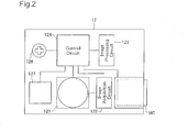
- Fig. 2 is a block diagram schematically illustrating the structure of the digital still camera 12 working as the input device of generating image data.
- the digital still camera 12 focuses an image through an optical lens on a charge coupled device (CCD) so as to electrically record a still image.
- CCD charge coupled device
- the digital still camera 12 includes an optical circuit 121 having a CCD that converts optical signals into electrical signals, an image acquisition circuit 122 that controls the optical circuit 121 to acquire image data, an image processing circuit 123 that processes the acquired image data, and a control circuit 124 that controls these respective circuits.
- the digital still camera 12 further has a selection/decision button 126 as a user interface and a liquid crystal display 127 used for preview of photographed images and user interfaces.
- the shooting process (graphics data capture process) by the digital still camera 12 is carried out in the order: (1) setting of shooting mode by the user; (2) shooting (input of graphics data); (3) image processing; and (4) recording of graphics file.
- Shooting mode setting includes setting of lens focal distance. Setting of lens focal distance is carried out by exchanging lenses (not shown) or manipulating a zoom lens (not shown).
- the photographing is performed by pressing a shutter button by the user.
- the photographing is performed with a focal distance available by the lens equipped with the digital still camera 12.
- the photographing and the original image data generation are performed with an adjusted focal distance.
- the original image data thus generated are subjected to image processing for storage.
- This image processing is a pre -treatment of the original image data, prior to storage into the memory card MC.
- the general procedure converts the original image data into a JPEG format suitable for storage of photographic images. After conversion into the JPEG format, the procedure adds photographing information PI to the converted image data to create an image file.
- the photographing information PI regards photographing conditions and includes information representing the sele cted light metering.
- the process of acquiring image data in the digital still camera 12 terminates with recording of the image file into the memory card MC. The structure of the image file will be discussed later.
- Fig. 3 is a block diagram schematically showing the configuration of the computer PC and the color printer 20 as the output device of outputting image data.
- the computer PC has a slot 22 for reading an image file from the memory card MC inserted therein and a print data generation circuit 23 for generating print data, according to which the color printer 20 carries out printing.
- the print data generation circuit 23 includes a central processing unit (CPU) 231 that executes arithmetic operations for generation of print data, a hard disk 232 tha t stores programs executed by the CPU 231, results of the arithmetic operations by the CPU 231, and other data, and a random access memory (RAM) 233 that temporarily stores these programs and data.
- CPU central processing unit
- RAM random access memory
- the color printer 20 is capable of outputting color image s.
- One typical example of the color printer 20 is an ink jet printer that ejects four different color inks, cyan (C), magenta (M), yellow (Y), and black (K) on a printing medium to form a dot pattern and thereby complete a printed image.
- Fig. 4 schematically shows the structure of an image file GF in the embodiment of the invention.
- the image file GF has a file structure in conformity with Exchangeable image file format (Exif) for digital still cameras.
- This format is spec ified by Japan Electronics and Information Technology Industries Association (JEITA). According to this format, JPEG -Exif files that store compressed JPEG data as image data are included in Exif files (files of the Exif format).
- the image file GF include s an SOI marker segment 101 representing a header of compressed data, an APP1 marker segment 102 storing attribute information of the Exif format, an APP2 marker segment 103 storing Exif extended data, a DQT marker segment 104 defining a quantization table, a DHT marker segment 105 defining a Huffman table, a DRI marker segment 106 defining an insertion interval of a restart marker, an SOF marker segment 107 representing various parameters relating to frames, an SOS marker segment 108 representing various parameters relating to scanning, an EOI marker segment 109 representing a termination of the compressed data, and an image data storage area 110.
- the APP1 marker segment 102 stores an APP1 marker 1021, an Exif identification code 1022, a TIFF header and other attribute information 1023, and thumbnail image data 1024.
- the attribute information 1023 has a TIFF structure with a file header (TIFF header) and includes, in the case of an Exif-JPEG file, 0 th IFD storing attribute information relating to compressed image data, Exif IFD storing the photographing information PI and other attribute information inherent to the Exif format and 1 st IFD storing attribute information relating to thumbnail images.
- the Exif IFD is pointed by an offset from the TIFF header s tored in the 0 th IFD.
- Tags for identifying various pieces of information are used in the IFD, and the respective pieces of information may be referred to as tag names.
- FIG. 5 is an illustration showing an example of attribute information stored in the Ex if IFG of a graphics file GF.
- the attribute information includes tags of various kinds, including a tag relating to version and tags relating to shooting conditions.
- Tags relating to shooting conditions store exposure time, lens F stop, ISO sensitivity, shutter speed, aperture, luminance, lens focal distance, focal plane width resolution, focal plane height resolution, focal plane resolution unit, 35 mm-equivalent lens focal distance, and other parameters, stored as shooting information PI in accordance with predetermined offset. Recording of the shooting information PI is carried out during shooting by the digital still camera 12, as described previously .
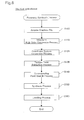
- FIG. 6 is a flowchart showing the processing routine of the panorama synthesis process in a computer PC.
- the CPU 231 reads the graphics file GF from the memory card MC which has been inserted into the slot 22, and stores this in the RAM 233 belonging to the print data generating circ uit 23.
- the graphics file GF stores graphics data in the JPEG file format as the graphics data GD.
- Graphics data in the JPEG file format is composed of compressed YCbCr data.
- Step S110 the CPU 231 performs a color conversion process after having expanded the compressed YCbCr data.
- the YCbCr data is converted to RGB data.
- the reason for conversion to RGB data is that RGB data is used in image processing in the personal computer PC and in the color printer 2 0.
- Both the RGB and the YCbCr data take the form of planar images composed of a plurality of pixels in a plane (herein also termed planar pixels) arrayed on a plane.
- Step S120 the CPU 231 performs a coordinate conversion process on the RGB data.
- This coordinate conversion process is specifically a process in which the RGB data, which is a planar image, is projected onto a cylindrical surface positioned in a cylindrical coordinate system, to generate graphics data on a cylindrical surface.
- graphics data generated in this way shall be referred to as cylindrical RGB data
- RGB data composed as a planar image shall be referred to as planar RGB data.
- FIGS. 7(a) and 7(b) are illustrations depicting the positional relationship between pla nar RGD data MI and a projection plane CYL in a cylindrical coordinate system.
- FIG. 7(a) depicts the positional relationship between the optical system and the image pickup device of the digital still camera 12.
- the optical system is shown as a lens L.
- the image pickup device is composed as a CCD (Charge-Coupled Apparatus) having a flat photoreceptor surface.
- CCD Charge-Coupled Apparatus
- the lens L replaces the several lenses of the digital still camera 12 optical system with a single lens having the same effect.
- the center of the lens L is termed the principal point, and the plane passing through the principal point and perpendicular to the optical axis Laxis is termed the principal plane.
- the lens L there are defined a n objective surface indicating a subject, and an imaging surface which focuses light from the subject.
- the objective surface and the imaging surface are defined as being situated spaced apart from the principal plane in the optical direction, by an objective surface distance a and an imaging surface distance b, respectively.
- the image pickup device is positioned with its photoreceptor surface aligned with this imaging surface.
- light from the subject on the objective surface passes through the lens L and is focused on the photoreceptor surface of the image pickup device.
- FIG. 7(b) depicts the planar RGB data MI being projected onto the projection plane CYL. Since the planar RGB data MI is graphics data that has been generated using the image pickup device, pixel values of the planar pixels PXL thereof are values that originally were generated depending on light incident on the image pickup pixels disposed on the imaging surface.
- the projection plane CYL is established as part of a cylindrical surface which is a collection of a plurality of points situated away by imaging surface distance b from the axis Caxis of the cylindrical coordinate system.
- the axis Caxis is an axis that passes through a point PP corresponding to the principal point of FIG. 7(a) and extends in the vertical direction of the planar RGB data MI.
- the imaging surface distance b substantially corresponds to lens focal distance.
- the value stored in the Exif IFD of the graphics file GF (FIG. 5) can be used as lens focal distance.
- FIG. 8 is an illustration showing the processing routine of the coo rdinate conversion process in the first embodiment of the invention.
- the CPU 231 reads out from the graphics file GF data for use in the coordinate conversion process.
- Data for use in the coordinate conversion process includes lens focal di stance, focal plane resolution unit, resolution of focal plane width, and resolution of focal plane height.
- Lens focal distance refers to the actual focal distance of the shooting lens; as noted, it substantially corresponds to the distance from the center of a hypothetic single convex lens to the image pickup device where the light is focused.
- Focal plane resolution unit specifies the unit for measuring resolution of the width of the focal plane and resolution of the height of the focal plane.
- Resolution of focal plane width represents the number of pixels in the image width direction per unit of focal plane resolution.
- Resolution of focal plane height represents the number of pixels in the image height direction per unit of focal plane resolution.
- focal plane refers to the imaging plane in which light from the subject focuses; as noted, it is aligned with the photoreceptor surface of the image pickup device.
- Step S220 the CPU 231 performs the following processes.
- Placement of the planar RGB data is carried out at a location situated away, by the equivalent of the lens focal distance, from the axis Caxis, and with an orientation such that the centerline CL extending in the height direction of the planar RGB data parallel with the axis Caxis.
- the reason for placing the data so that the centerline CL extending in the h eight direction of the planar RGB data parallel with the axis Caxis is in order to control distortion of the image in the image lateral direction in the panorama synthesis process, which typically involves seaming together images in the lateral direction.
- Step S230 the CPU 231 determines the size of the planar pixels of the planar RGB data, and the size of the cylindrical pixels on the projection plane CYL.
- the planar pixel size specifically, pixel size in the width direction can be de termined by dividing the focal plane resolution unit by the resolution of focal plane width, and pixel size in the height direction by dividing the focal plane resolution unit by the resolution of focal plane height.
- the planar pixel size determined in th is way will correspond to image pickup device pixel size, in the event that there no resampling of data obtained from the image pickup device.
- FIGS. 9(a) and 9(b) are illustrations depicting the positional relationship between planar RGB data and the projection plane CYL, viewed from the axis Caxis direction.
- FIG. 9(a) shows FIG. 7(b) viewed from above.
- FIG. 9(b) is a partial enlarged view of FIG. 9(a).
- a plurality of planar pixel rows C are shown in the planar RGB data MI.
- a planar pixel row C is a pixel row composed of a plurality of planar pixels lined up in the vertical direction in the planar RGB data MI.
- FIG. 9(a) there are shown 11 planar pixel rows, from planar pixel row C5L to planar pixel row C5R.
- the planar pixels contained in each planar pixel row all have the same height Z 0 (in the axis Caxis direction).
- FIG. 9(a) there is also shown a plurality of cylindrical pixel rows P within the projection plane CYL.
- a cylindrical pixel row P is a pixel row composed of a plurality of planar pixels lined up in the height direction in the projection plane CYL.
- FIG. 9(a) there are shown 9 cylindrical pixel rows, from cylindrical pixel row P4L to cylindrical pixel row P4R. All of the cylindrical pixel rows have width of the same given angle ⁇ 0 .
- the cylindrical pixels contained in each cylindrical pixel row all have the same height Z 0 (not shown).
- the angle ⁇ 0 representing cylindrical pixel width is established on the basis of a planar pixel PXL in proximity to the optical axis Laxis. Specifically, a cylindrical pixel row P0 is determined by projecting a planar pixel C0 onto the projection plane CYL, and the angle ⁇ 0 of the cylindrical pixel row P0 so determined is designated as the angle of the cylindrical pixel rows.
- cylindrical pixels not shown in this way, it is possible to construct a cylindrical image in the projection plane CYL (Step S240).
- Step S250 the CPU 231 extracts the pixel values of the cylindrical pixels, from the pixels values of the plan ar pixels of the planar RGB data MI.
- FIG. 9(b) is a partial enlarged view of FIG. 9(a), illustrating the method for extracting pixel values of cylindrical pixels using a bilinear interpolation method.
- the RGB data is assumed to be one -dimensional data having only one row of planar pixels in the height direction; however, it could easily be expanded to two -dimensional data by carrying out the same process in the height direction.
- FIG. 9(b) are shown a cylindrical pixel P3R, the centerline P3RCL of the cylindrical pixel P3R, and the projection point X1 of the centerline P3RCL onto the planar RGB data MI.
- the centerline P3RCL is a line extending from the axis Caxis (FIG. 9(a)) towards the center of the cylindrical pixel P3R.
- the pixel value of the cylindrical pixel P3R can be extracted in the following manner, from the pixel values of the planar pixels C3R, C4R.
- the projection point X1 is projected into the planar pixel C3R, and is situated a distance 50a away from the center location of the planar pixel C3R, and a distance 50b away from the center location of the planar pixel C4R. These distances 50a, 50b can be calculated from the planar RGB data and the lens focal distance by the CPU 231.
- the pixel value of the cylindrical pixel P3R can readily be extracted with the calculation equation: ((pixel value of planar pixel C3R x distance 50b + pixel value of planar pixel C4R x distance 50a)/(distance 50 a + distance 50b)).
- Other calculation methods include the cubic convolution method and other extraction methods.
- FIG. 10 is an illustration showing distortion of an image produced during generation of graphics data using a planar image pickup device.
- two sets of planar RGB data M1, M2 generated by projecting a given subje ct m from the same point, but at separate angles.
- the two sets of planar RGB data M1, M2 are projected respectively on two optical axes Laxis1, Laxis 2.
- Laxis1 the optical axes
- Laxis 2 the subject m is positioned in the center portion of the image
- the planar RGB data M1 the subject m is positioned at the left edge of the image.
- the subject m has apparent size substantially the same as the planar pixel, whereas in the planar RGB data M2 it has apparent size larger than the planar pixel.
- the apparent size of the subject m in the planar RGB data will differ depending on the location at which the subject m is positioned in the image. As a result, image distortion occurs.
- FIG. 12 illustrates generation of two sets of cylindrical graphics data having the same focal distance from a scene View.
- the two sets of cylindrical graphics data are data generated by means of shooting the two frames Fa1, Fb1 shown in FIG. 12(a).
- the graphics data shown in FIG. 12(b) has been derived by developing data shot in frame Fa1 and converted to a cylindrical image;
- the graphics data shown in FIG. 12(c) has been derived by developing data shot in frame Fb1 and converted to a cylindrical image.
- Step S130 the CPU 231 carries out a feature point extraction process on the two sets of cylindrical image data.
- the feature point extraction process is a process for extracting feature points that well represent an external characteristic of a subject in an image.
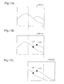
- FIGS. 13(a), 13(b), and 13(c) are illustrations depicting feature points extracted from each set of cylindrical graphics data. Each feature point need not have size equivalent to one pixel, but may be an area composed of several pixels.
- the feature point extraction process may be carried out by the following method, for example.
- the CPU 231 extracts the contour line as a collection of points, using a Sobel filter or other contour line extraction filter.
- FIG. 13(a) shows contour line data PICTa1 generated by performing a con tour line extraction process on cylindrical image data PICTa0 (FIG. 12(b)).
- FIG. 13(b) shows feature point data PICTa2 generated by performing a feature point extraction process on contour line data PICTa1.
- FIG. 13(c) shows feature point data PICTb2 generated by performing a feature point extraction process on contour line data PICTb1 (not shown).
- the feature point data PICTa2 includes two feature points Ca1, Ca2, and the feature point data PICTb2 includes two feature points Cb1, Cb2.
- contour lines are shown overlapped to facilitate understanding.
- Step S140 the CPU 231 performs a corresponding point search process on two sets of feature point data PICTa2, PICTb2.
- the corresponding point search process is a process that searches for features points that correspond to one another am ong multiple images. This process is a process for determining a given location in a given subject among multiple sets of graphics data targeted for panorama synthesis.
- the corresponding point search process can be carried out by means of searching for a collection of a plurality of feature points that meet the following criteria, for example.
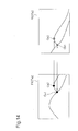
- FIG. 14 is an illustration showing the corresponding point search process being carried out.
- the feature point data PICTa2 includes two feature points Ca1, Ca2, and the feature point data PICTb2 includes two feature points Cb1, Cb2.
- Feature point Ca1 an d feature point Cb1 represent the same subject, and thus the surrounding pixels have approximate pixel values.
- feature point Ca1 and feature point Ca2 will be found to be corresponding approximate feature points.
- feature point Ca2 and feature point Cb2 will be found to be corresponding approximate feature points.
- feature point Ca1 of feature point data PICT a2 corresponds to feature point Cb1 of feature point data PICTb2
- feature point Ca2 of feature point data PICTa2 corresponds to feature point Cb2 of feature point data PICTb2.
- Step S150 the CPU 231 performs a synthesis process of two sets of cylindrical graphics data.
- the synthesis process is a process for synthesizing multiple sets of graphics data in such a way that corresponding feature points align.
- FIGS. 15(a) and 15(b) are illustrations giving a description of the synthesis process.
- the synthesis process is carried out by determining the positional relationship of two images in such a way that corresponding feature points are positioned in proximity, and the subjecting each image to localized deformation so that positions of correspond ing feature points align.
- FIG. 15(a) shows two sets of feature point data PICTa2, PICTb2 arranged so that corresponding feature points are positioned in proximity.
- feature point Ca1 belonging to feature point data PICTa2 is located just to the right of feature point Cb1 belonging to feature point data PICTb2.
- Feature point Ca2 belonging to feature point data PICTa2 is located just to the left of feature point Cb2 belonging to feature point data PICTb2.
- this placement is due to the fact that the distance between feature point Ca1 and feature point Ca2 is smaller than the distance between feature point Cb1 and Cb2, due to distortion of the images.
- the presence of distortion in each image is due to the fact that, while the image distortion shown in FIG. 10 has been suppressed, there is residual distortion due to lens aberration. Where it is assumed that each image will have some distortion in this way, it is preferable to determine relative positions of the two images s o as to minimize the squares of the distances between corresponding points, for example.
- the functions of the focal distance determiner, the synthesis area establisher, the spheroidal image generator, the feature point extractor, the correspondence relationship determiner, the spheroidal image synthesizer, and the planar image generator recited in the claims are carried out by the CPU 231.
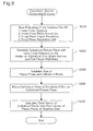
- FIGS. 16(a), 16(b), and 16(c) are illustrations depicting graphics data representing a single seamless image being generated from two sets of graphics data having different focal distances.
- the two sets of graphics data are the graphics data generated by means of shooting the two frames Ff1, Fn1 shown in FIG. 16(a).
- the reason that the two fra mes Ffl, Fn1 differ in size (angle of field) is that the focal distance has been changed by means of a zoom operation or changing lenses.
- the graphics data of frame Ffl has been generated at a relatively long focal distance
- the graphics data of frame Fn1 has been generated at a relatively short focal distance.
- FIG. 16(b) shows one graphics data frame F3 generated from two sets of graphics data.
- the size of frame F3 has image width generated by synthesizing the two frames Ffl, Fn1, with the height of the frame Ff1 which, of the two frames Ffl, Fn1, has the longer focal distance (smaller angle of field) being trimmed.
- FIG. 16(c) shows a seamless planar image PICT2 generated to have the frame F3 determined in this way.
- FIG. 17 is an illustration depicting generation of two sets of cylindrical graphics data from two sets of graphics data having different focal distances.
- Planar RGB data MIn is data generated by shooting the frame Fn1.
- Planar RGB data MIf is data generated by shooting the frame Ffl (FIG. 16(a)).
- the planar RGB data MIn and the planar RGB data MIf are positioned away from the cylindrical coordinate system axis Caxis in the optical axis Laxis direction, by a focal distance Rn and a focal distance Rf, respectively.
- the foca 1 distance Rn and focal distance Rf are values for lens focal distance read from the Exif IFD of each graphics file GF.
- the projection plane CYL on the cylindrical coordinate system is a projection plane established with the cylindrical coordinate system axis Caxis as its center, and having a radius equal to the focal distance Rf.
- the focal distance Rf is the longer of the two different focal distances established by shooting the two sets of planar RGB data MIn, MIf.
- the angle ⁇ 0 representing the cylindrical pixel width is established by a method similar to that of the first embodiment (FIG. 9(a)), on the basis of the planar pixels (not shown) of the planar RGB data MIf.
- the reason that the cylindrical pixel angle ⁇ 0 is established on the basis of the planar pixels of the planar RGB data MIf is that if it were based on the planar RGB data MIn, the cylindrical pixel angle ⁇ 0 would be excessive with respect to the planar RGB data MIf, and information belonging to the planar RGB data MIf would be lost. On the other hand, if the cylindrical pixel angle ⁇ 0 were made smaller than this, the amount of data of the cylindrical image would become excessive with respect to information belonging to the planar RGB data MIf, MIn.
- the pixel value of the cylindrical pixe 1 P4L can be calculated as follows from pixel values of planar pixels of the planar RGB data MIf, MIn, in the same manner as in the first embodiment.
- the cylindrical image pixel P4L generated by converting the planar RGB data MIf is calculated from two pixels C4Lf, C5Lf of the planar RGB data MIf.
- the cylindrical image pixel P4L generated by converting the planar RGB data MIn is calculated from two pixels C2Ln, C3Ln of the planar RGB data MIn.
- the invention is applicable to case s in which a panorama synthesis process is carried out on two sets of graphics data having different focal distances.
- the software may be provided in a form stored on a computer -readable recording medium.
- "computer-readable recording medium” is not limited to portable recording media such as flexible disks and CD -ROM, but includes also various flavors of RAM, ROM, and other computer internal storage apparatus, as well as hard disks and other external storage apparatus fixed in a computer.
- This invention is applicable to computer output apparatus.
Abstract
This invention is an image processing apparatus for generating graphics data representing a single seamless planar image synthesized from a multiple sets of graphics data contained in a plurality of graphics files. Each of the plurality of graphics files contains graphics data composed of a multiplicity of planar pixels arrayed in a plane to create a planar image. This image processing apparatus establishes a spheroidal or cylindrical projection plane for synthesis of the multiple sets of graphics data. <IMAGE>
Description
The present invention relates to image processing technology for seaming together
multiple data representing an image.
In recent years, it has become common practice to capture photos using a digital still
camera (DSC), and to then store the graphics data representing the photos on a computer. A
process termed panorama synthesis, in which data for multiple images is synthesized to produce
graphics data representing a single seamless image is sometimes carried out as well.
However, images generated by a digital still camera have some distortion, particularly in
peripheral edge portions. This distortion can create the problem of degraded image quality in
image areas that are seamed together when synthesizing multiple images. One cause of this
distortion is that light entering through the optical system of the digital camera is projected onto
an image pickup device having a flat photoreceptor su rface.
With the foregoing in view, it is an object of the present invention to provide technology
that overcomes the aforementioned drawbacks of the conventional art, by controlling image
degradation produced in the process of synthesizing data for multiple images generated using a
flat image pickup device.
In order to attain the above and the other objects of the present invention, there is provided
the first configuration of image processing apparatus for generating graphics data representing a
single seamless planar image synthesized from a multiple sets of graphics data contained in a
plurality of graphics files, in response to the plurality of graphics files each of which contains the
graphics data composed of a multi plicity of planar pixels arrayed in a plane for representing a
planar image. The image processing apparatus comprising a synthesis area establisher
configured to establish a spheroidal projection plane centered on a predetermined point, as an
area for synthesis of the multiple sets of graphics data; a spheroidal image generator configured
to generate a plurality of spheroidal images, by projecting each of planar images represented by
each of the multiple sets of graphics data onto the projection plane; a feature point extractor
configured to extract a feature point which is an area having a predetermined characteristic, from
each of the plurality of spheroidal images; a correspondence relationship determiner
configured to determine a correspondence relation ship of the extracted feature points , between
the plurality of spheroidal images; a spheroidal image synthesizer configured to generate
seamless spheroidal graphics data representing a single seamless spheroidal image , by
synthesizing a plurality of graphics data each of which representing each of the spheroidal
images, with reference to the determined correspondence relationship; and a planar image
generator configured to generate the graphics data representing the single seamless planar image ,
from the seamless spheroidal image graphics data.
According to this first configuration of the invention, a spheroidal projection plane
centered on a predetermined point is established as an area for synthesizing the multiple graphics
data, and planar images representing data for each of the multiplicity of images are projected
onto the established projection plane in order to generate a multiplicity of spheroidal images,
which spheroidal images are then synthesized. According to this aspect, since images are
synthesized on a spheroidal projection plane, it is possible to control degradation in image
quality produced in the process of synthesizing data for multiple images generated using a flat
image pickup device.
In the image processing apparatus of the present in vention, the plurality of graphics files
may further include image attribute information which is attribute information of the graphics
data. The image processing apparatus may further comprise a focal distance determiner
configured to determine a focal distance of an optical system used to generate the multiple sets of
graphics data for each of the multiple set of graphics data, in response to the image attribute
information; and the spheroidal image generator generates the plurality of spheroidal images by
projecting each planar image represented by each of the multiple sets of graphics data onto the
projection plane, the each planar images being placed at a location away from the predetermined
point to the projection plane side, by the focal distance corresponding to each of the multiple sets
of graphics data.
By so doing, it is possible to carry out panorama synthesis even where the data for a
multiplicity of images has been created at different magnification by means of using the zoom
function during s hooting, for example.
In the image processing apparatus of the present invention, the image attribute
information may include lens focal distance representing focal distance of a shooting lens; focal
plane resolution unit specifying an unit of resolution in a focal plane of the optical system; focal
plane height resolution representing a pixel count in a pixel height direction per the focal plane
resolution unit; and focal plane width resolution representing a pixel count in a pixel width
direction per the focal plane resolution unit; the focal distance determiner determines the lens
focal distance to be the focal distance; and the spheroidal image generator determines a pixel size
in a width direction by means of dividing the focal plane resolution unit by focal plane width
resolution, and also determines a pixel size in a height direction by means of dividing the focal
plane resolution unit by the focal plane height resolution.
In the image processing apparatus of the present invention, the image attribute
information may include 35 mm-equivalent lens focal distance which is a value of focal distance
converted to a 35 mm film camera basis. The focal distance determiner may determine the 35
mm-equivalent lens focal distance to be the focal distance. The spheroidal image generator may
determine 35 mm film size as a size of the planar image.
In the preferred image processing apparatus of the present invention, the image attribute
information includes focal plane resolution unit specifying an unit of resolution in a focal plane
of the optical system; focal plane height resolution representing a pixel count in a pixel height
direction per the focal plane resolution unit; and focal plane width resolution representing a pixel
count in a pixel width direction per the focal plane resolution unit. The spheroidal image
generator comprises: a spheroidal pixel establisher configured to establish spheroidal pixels on
the spheroidal projection plane, the spheroidal pixel being allocated in a height direction by an
angle divided by a largest one of the determined focal distances and the focal plane height
resolution, and being allocated in a width direction by an angle divided by the largest determined
focal distance and the focal plane width resolution; and a spheroidal pixel value determiner
configured to determine each pixel value for each of the spheroidal pixel s, according to a pixel
value of a planar pixel projected onto each of the spheroidal pixels.
In this way, by establishing spheroidal pixels on the basis of th e largest one among the
determined focal point distances, it becomes possible to carry out panorama synthesis without
reducing the amount of information of planar images having the smallest pixels, and without
including an excessive amount of information i n the spheroidal images generated from the planar
images.
The second configuration of the invention is an image processing apparatus for
generating graphics data representing a single seamless planar image synthesized from a multiple
sets of graphics data contained in a plurality of graphics files, in response to the plurality of
graphics files each of which contain s the graphics data composed of a multiplicity of planar
pixels arrayed in a plane for representing a planar image. The image processing appar atus
comprises: a synthesis area establisher configured to establish a cylindrical projection plane
centered on a predetermined axis, as an area for synthesis of the multiple sets of graphics data; a
cylindrical image generator configured to generate a plurality of cylindrical images, by
projecting each of planar images represented by each of the multiple sets of graphics data onto
the projection plane; a feature point extractor configured to extract a feature point which is an
area having a predetermined characteristic, from each of the plurality of cylindrical images; a
correspondence relationship determiner configured to determine a correspondence relationship of
the extracted feature points, between the plurality of cylindrical images; a cylindrical image
synthesizer configured to generate seamless cylindrical graphics data representing a single
seamless cylindrical image, by synthesizing a plurality of graphics data each of which
representing each of the cylindrical images, with reference to the determin ed correspondence
relationship; and a planar image generator configured to generate the graphics data representing
the single seamless planar image , from the seamless cylindrical image graphics data.
In the preferred image processing apparatus of the pres ent invention, the cylindrical
image generator establishes the axis parallel to the height direction established in the graphics
data.
By so doing, it is possible to reduce image distortion of in the lateral direction of images
during the panorama synthesis process, which typically involves seaming together in the lateral
direction.
The technique of the present invention is actualized by a variety of applications, which
include image processing methods, computer programs that attain the functions of such
apparatuses and methods, recording media in which such computer programs are recorded, and
data signals that include such computer programs and are embodied in carrier waves.
The following description of the best mode for carrying out the invention on the basis of
embodiments shall be made in the order indicated below.
Fig. 1 illustrates an image processing system 10 in one embodiment of the invention.
The image processing system 10 includes a digital still camera 12 functioning as an input device
that generates original image data, a personal computer PC functioning as an image processing
device that performs image processing of the original image data generated by the digital still
camera 12, and a color printer 20 functioning as an output device th at outputs processed images.
The digital still camera 12, the personal computer PC, and the color printer 20 are
mutually connectable via a cable CV. In the state of connection by the cable CV, the digital still
camera 12 and the other constituents are allowed to transmit and receive image files via the cable
CV. In the status of no connection by the cable CV, the digital still camera 12 and the other
constituents are allowed to transmit image files therebetween via a memory card MC.
Fig. 2 is a block diagram schematically illustrating the structure of the digital still camera
12 working as the input device of generating image data. The digital still camera 12 focuses an
image through an optical lens on a charge coupled device (CCD) so as to electrically record a
still image.
The digital still camera 12 includes an optical circuit 121 having a CCD that converts
optical signals into electrical signals, an image acquisition circuit 122 that controls the optical
circuit 121 to acquire image data, an image processing circuit 123 that processes the acquired
image data, and a control circuit 124 that controls these respective circuits. The digital still
camera 12 further has a selection/decision button 126 as a user interface and a liquid crystal
display 127 used for preview of photographed images and user interfaces.
The shooting process (graphics data capture process) by the digital still camera 12 is
carried out in the order: (1) setting of shooting mode by the user; (2) shooting (input of graphics
data); (3) image processing; and (4) recording of graphics file. Shooting mode setting includes
setting of lens focal distance. Setting of lens focal distance is carried out by exchanging lenses
(not shown) or manipulating a zoom lens (not shown).
The photographing is performed by pressing a shutter button by the user. In response to
the press of the shutter button, the photographing is performed with a focal distance available by
the lens equipped with the digital still camera 12. For example, when photographed with a zoom
lens providing a variable focal distance in response to the user operation, the photographing and
the original image data generation are performed with an adjusted focal distance.
The original image data thus generated are subjected to image processing for storage.
This image processing is a pre -treatment of the original image data, prior to storage into the
memory card MC. The general procedure converts the original image data into a JPEG format
suitable for storage of photographic images. After conversion into the JPEG format, the
procedure adds photographing information PI to the converted image data to create an image file.
The photographing information PI regards photographing conditions and includes
information representing the sele cted light metering. The process of acquiring image data in the
digital still camera 12 terminates with recording of the image file into the memory card MC. The
structure of the image file will be discussed later.
Fig. 3 is a block diagram schematically showing the configuration of the computer PC
and the color printer 20 as the output device of outputting image data. The computer PC has a
slot 22 for reading an image file from the memory card MC inserted therein and a print data
generation circuit 23 for generating print data, according to which the color printer 20 carries out
printing. The print data generation circuit 23 includes a central processing unit (CPU) 231 that
executes arithmetic operations for generation of print data, a hard disk 232 tha t stores programs
executed by the CPU 231, results of the arithmetic operations by the CPU 231, and other data,
and a random access memory (RAM) 233 that temporarily stores these programs and data.
The color printer 20 is capable of outputting color image s. One typical example of the
color printer 20 is an ink jet printer that ejects four different color inks, cyan (C), magenta (M),
yellow (Y), and black (K) on a printing medium to form a dot pattern and thereby complete a
printed image.
Fig. 4 schematically shows the structure of an image file GF in the embodiment of the
invention. The image file GF has a file structure in conformity with Exchangeable image file
format (Exif) for digital still cameras. This format is spec ified by Japan Electronics and
Information Technology Industries Association (JEITA). According to this format, JPEG -Exif
files that store compressed JPEG data as image data are included in Exif files (files of the Exif
format).
The image file GF include s an SOI marker segment 101 representing a header of
compressed data, an APP1 marker segment 102 storing attribute information of the Exif format,
an APP2 marker segment 103 storing Exif extended data, a DQT marker segment 104 defining a
quantization table, a DHT marker segment 105 defining a Huffman table, a DRI marker segment
106 defining an insertion interval of a restart marker, an SOF marker segment 107 representing
various parameters relating to frames, an SOS marker segment 108 representing various
parameters relating to scanning, an EOI marker segment 109 representing a termination of the
compressed data, and an image data storage area 110.
The APP1 marker segment 102 stores an APP1 marker 1021, an Exif identification code
1022, a TIFF header and other attribute information 1023, and thumbnail image data 1024. The
attribute information 1023 has a TIFF structure with a file header (TIFF header) and includes, in
the case of an Exif-JPEG file, 0th IFD storing attribute information relating to compressed image
data, Exif IFD storing the photographing information PI and other attribute information inherent
to the Exif format and 1st IFD storing attribute information relating to thumbnail images. The
Exif IFD is pointed by an offset from the TIFF header s tored in the 0th IFD. Tags for identifying
various pieces of information are used in the IFD, and the respective pieces of information may
be referred to as tag names.
FIG. 5 is an illustration showing an example of attribute information stored in the Ex if
IFG of a graphics file GF. The attribute information includes tags of various kinds, including a
tag relating to version and tags relating to shooting conditions. Tags relating to shooting
conditions store exposure time, lens F stop, ISO sensitivity, shutter speed, aperture, luminance,
lens focal distance, focal plane width resolution, focal plane height resolution, focal plane
resolution unit, 35 mm-equivalent lens focal distance, and other parameters, stored as shooting
information PI in accordance with predetermined offset. Recording of the shooting information
PI is carried out during shooting by the digital still camera 12, as described previously .
FIG. 6 is a flowchart showing the processing routine of the panorama synthesis process in
a computer PC. In Step S100, the CPU 231 reads the graphics file GF from the memory card
MC which has been inserted into the slot 22, and stores this in the RAM 233 belonging to the
print data generating circ uit 23. The graphics file GF stores graphics data in the JPEG file
format as the graphics data GD. Graphics data in the JPEG file format is composed of
compressed YCbCr data.
In Step S110, the CPU 231 performs a color conversion process after having expanded
the compressed YCbCr data. By means of this color conversion process, the YCbCr data is
converted to RGB data. The reason for conversion to RGB data is that RGB data is used in
image processing in the personal computer PC and in the color printer 2 0. Both the RGB and the
YCbCr data take the form of planar images composed of a plurality of pixels in a plane (herein
also termed planar pixels) arrayed on a plane.
In Step S120, the CPU 231 performs a coordinate conversion process on the RGB data.
This coordinate conversion process is specifically a process in which the RGB data, which is a
planar image, is projected onto a cylindrical surface positioned in a cylindrical coordinate
system, to generate graphics data on a cylindrical surface. Hereinafter, graphics data generated
in this way shall be referred to as cylindrical RGB data, and RGB data composed as a planar
image shall be referred to as planar RGB data.
FIGS. 7(a) and 7(b) are illustrations depicting the positional relationship between pla nar
RGD data MI and a projection plane CYL in a cylindrical coordinate system. FIG. 7(a) depicts
the positional relationship between the optical system and the image pickup device of the digital
still camera 12. The optical system is shown as a lens L. The image pickup device is composed
as a CCD (Charge-Coupled Apparatus) having a flat photoreceptor surface.
The lens L replaces the several lenses of the digital still camera 12 optical system with a
single lens having the same effect. The center of the lens L is termed the principal point, and the
plane passing through the principal point and perpendicular to the optical axis Laxis is termed
the principal plane. As regards the lens L, there are defined a n objective surface indicating a
subject, and an imaging surface which focuses light from the subject. The objective surface and
the imaging surface are defined as being situated spaced apart from the principal plane in the
optical direction, by an objective surface distance a and an imaging surface distance b,
respectively.
The image pickup device is positioned with its photoreceptor surface aligned with this
imaging surface. By means of this arrangement, light from the subject on the objective surface
passes through the lens L and is focused on the photoreceptor surface of the image pickup
device.
FIG. 7(b) depicts the planar RGB data MI being projected onto the projection plane CYL.
Since the planar RGB data MI is graphics data that has been generated using the image pickup
device, pixel values of the planar pixels PXL thereof are values that originally were generated
depending on light incident on the image pickup pixels disposed on the imaging surface.
The projection plane CYL is established as part of a cylindrical surface which is a
collection of a plurality of points situated away by imaging surface distance b from the axis
Caxis of the cylindrical coordinate system. The axis Caxis is an axis that passes through a point
PP corresponding to the principal point of FIG. 7(a) and extends in the vertical direction of the
planar RGB data MI. It will be understood that the imaging surface distance b substantially
corresponds to lens focal distance. The value stored in the Exif IFD of the graphics file GF (FIG.
5) can be used as lens focal distance. By so doing, a cylindrical image having a plurality of
cylindrical pixels defined by the size Z0 in the Caxis direction and the angle 0 can be
constructed on the projection plane CYL.
FIG. 8 is an illustration showing the processing routine of the coo rdinate conversion
process in the first embodiment of the invention. In Step S210, the CPU 231 reads out from the
graphics file GF data for use in the coordinate conversion process. Data for use in the coordinate
conversion process includes lens focal di stance, focal plane resolution unit, resolution of focal
plane width, and resolution of focal plane height. Lens focal distance refers to the actual focal
distance of the shooting lens; as noted, it substantially corresponds to the distance from the
center of a hypothetic single convex lens to the image pickup device where the light is focused.
Focal plane resolution unit specifies the unit for measuring resolution of the width of the
focal plane and resolution of the height of the focal plane. Resolution of focal plane width
represents the number of pixels in the image width direction per unit of focal plane resolution.
Resolution of focal plane height represents the number of pixels in the image height direction per
unit of focal plane resolution. Her e, focal plane refers to the imaging plane in which light from
the subject focuses; as noted, it is aligned with the photoreceptor surface of the image pickup
device.
In Step S220, the CPU 231 performs the following processes.
Placement of the planar RGB data is carried out at a location situated away, by the
equivalent of the lens focal distance, from the axis Caxis, and with an orientation such that the
centerline CL extending in the height direction of the planar RGB data parallel with the axis
Caxis. The reason for placing the data so that the centerline CL extending in the h eight direction
of the planar RGB data parallel with the axis Caxis is in order to control distortion of the image
in the image lateral direction in the panorama synthesis process, which typically involves
seaming together images in the lateral direction.
In Step S230, the CPU 231 determines the size of the planar pixels of the planar RGB
data, and the size of the cylindrical pixels on the projection plane CYL. With regard to the
planar pixel size, specifically, pixel size in the width direction can be de termined by dividing the
focal plane resolution unit by the resolution of focal plane width, and pixel size in the height
direction by dividing the focal plane resolution unit by the resolution of focal plane height. The
planar pixel size determined in th is way will correspond to image pickup device pixel size, in the
event that there no resampling of data obtained from the image pickup device.
FIGS. 9(a) and 9(b) are illustrations depicting the positional relationship between planar
RGB data and the projection plane CYL, viewed from the axis Caxis direction. FIG. 9(a) shows
FIG. 7(b) viewed from above. FIG. 9(b) is a partial enlarged view of FIG. 9(a). In FIG. 9(a), a
plurality of planar pixel rows C are shown in the planar RGB data MI. A planar pixel row C is a
pixel row composed of a plurality of planar pixels lined up in the vertical direction in the planar
RGB data MI. In FIG. 9(a) there are shown 11 planar pixel rows, from planar pixel row C5L to
planar pixel row C5R. The planar pixels contained in each planar pixel row all have the same
height Z0 (in the axis Caxis direction).
In FIG. 9(a) there is also shown a plurality of cylindrical pixel rows P within the
projection plane CYL. A cylindrical pixel row P is a pixel row composed of a plurality of planar
pixels lined up in the height direction in the projection plane CYL. In FIG. 9(a) there are shown
9 cylindrical pixel rows, from cylindrical pixel row P4L to cylindrical pixel row P4R. All of the
cylindrical pixel rows have width of the same given angle 0. The cylindrical pixels contained in
each cylindrical pixel row all have the same height Z 0 (not shown).
The angle 0 representing cylindrical pixel width is established on the basis of a planar
pixel PXL in proximity to the optical axis Laxis. Specifically, a cylindrical pixel row P0 is
determined by projecting a planar pixel C0 onto the projection plane CYL, and the angle 0 of
the cylindrical pixel row P0 so determined is designated as the angle of the cylindrical pixel
rows. By establishing cylindrical pixels (not shown) in this way, it is possible to construct a
cylindrical image in the projection plane CYL (Step S240).
In Step S250, the CPU 231 extracts the pixel values of the cylindrical pixels, from the
pixels values of the plan ar pixels of the planar RGB data MI. FIG. 9(b) is a partial enlarged view
of FIG. 9(a), illustrating the method for extracting pixel values of cylindrical pixels using a
bilinear interpolation method. In the extraction example hereinbelow, in order to fa cilitate the
description, the RGB data is assumed to be one -dimensional data having only one row of planar
pixels in the height direction; however, it could easily be expanded to two -dimensional data by
carrying out the same process in the height direction.
In FIG. 9(b) are shown a cylindrical pixel P3R, the centerline P3RCL of the cylindrical
pixel P3R, and the projection point X1 of the centerline P3RCL onto the planar RGB data MI.
The centerline P3RCL is a line extending from the axis Caxis (FIG. 9(a)) towards the center of
the cylindrical pixel P3R.
The pixel value of the cylindrical pixel P3R can be extracted in the following manner,
from the pixel values of the planar pixels C3R, C4R. The projection point X1 is projected into
the planar pixel C3R, and is situated a distance 50a away from the center location of the planar
pixel C3R, and a distance 50b away from the center location of the planar pixel C4R. These
distances 50a, 50b can be calculated from the planar RGB data and the lens focal distance by the
CPU 231.
Where a bilinear interpolation method is used, the pixel value of the cylindrical pixel P3R
can readily be extracted with the calculation equation: ((pixel value of planar pixel C3R x
distance 50b + pixel value of planar pixel C4R x distance 50a)/(distance 50 a + distance 50b)).
Other calculation methods include the cubic convolution method and other extraction methods.
The reason for projecting the planar RGB data MI onto a cylindrical surface prior to synthesis of
the graphics data is as follows.
FIG. 10 is an illustration showing distortion of an image produced during generation of
graphics data using a planar image pickup device. In the drawing, there are shown two sets of
planar RGB data M1, M2 generated by projecting a given subje ct m from the same point, but at
separate angles. The two sets of planar RGB data M1, M2 are projected respectively on two
optical axes Laxis1, Laxis 2. In the planar RGB data M1, the subject m is positioned in the
center portion of the image, whereas in the planar RGB data M1, the subject m is positioned at
the left edge of the image.
As will be apparent from FIG. 10, in the planar RGB data M 1 the subject m has apparent
size substantially the same as the planar pixel, whereas in the planar RGB data M2 it has
apparent size larger than the planar pixel. In this way, the apparent size of the subject m in the
planar RGB data will differ depending on the location at which the subject m is positioned in the
image. As a result, image distortion occurs.
On the other hand, as will be apparent from FIG. 10, in a cylindrical image generated on
a cylindrical surface, the apparent size of the subject m will be the same regardless of the
location of the subject m on the image. In this way, by means of projecting a planar image onto
a cylindrical projection plane to effect conversion to a cylindrical image, it is possible to
minimize distortion in the lateral direction. By projecting onto a spheroidal coordinate system in
the manner shown in FIG. 11, it becomes possible to minimize distortion in both the height
direction and the width direction. Such an arrangement is markedly effective in cases where a
multiplicity of images are being synthesized in the height direction.
FIG. 12 illustrates generation of two sets of cylindrical graphics data having the same
focal distance from a scene View. The two sets of cylindrical graphics data are data generated
by means of shooting the two frames Fa1, Fb1 shown in FIG. 12(a). The graphics data shown in
FIG. 12(b) has been derived by developing data shot in frame Fa1 and converted to a cylindrical
image; the graphics data shown in FIG. 12(c) has been derived by developing data shot in frame
Fb1 and converted to a cylindrical image.
In Step S130, the CPU 231 carries out a feature point extraction process on the two sets
of cylindrical image data. The feature point extraction process is a process for extracting feature
points that well represent an external characteristic of a subject in an image. FIGS. 13(a), 13(b),
and 13(c) are illustrations depicting feature points extracted from each set of cylindrical graphics
data. Each feature point need not have size equivalent to one pixel, but may be an area
composed of several pixels.
The feature point extraction process may be carried out by the following method, for
example. First, the CPU 231 extracts the contour line as a collection of points, using a Sobel
filter or other contour line extraction filter. FIG. 13(a) shows contour line data PICTa1
generated by performing a con tour line extraction process on cylindrical image data PICTa0
(FIG. 12(b)).
Next, the CPU 231, using an SRA (Side effect resampling Algorithm) or other
resampling algorithm, extracts a feature point from the collection of points making up the
extracted contour line. FIG. 13(b) shows feature point data PICTa2 generated by performing a
feature point extraction process on contour line data PICTa1. FIG. 13(c) shows feature point
data PICTb2 generated by performing a feature point extraction process on contour line data
PICTb1 (not shown).
The feature point data PICTa2 includes two feature points Ca1, Ca2, and the feature point
data PICTb2 includes two feature points Cb1, Cb2. In FIG. 13(b) and FIGB. 13(c), contour lines
are shown overlapped to facilitate understanding.
In Step S140, the CPU 231 performs a corresponding point search process on two sets of
feature point data PICTa2, PICTb2. The corresponding point search process is a process that
searches for features points that correspond to one another am ong multiple images. This process
is a process for determining a given location in a given subject among multiple sets of graphics
data targeted for panorama synthesis.
The corresponding point search process can be carried out by means of searching for a
collection of a plurality of feature points that meet the following criteria, for example.
FIG. 14 is an illustration showing the corresponding point search process being carried
out. The feature point data PICTa2 includes two feature points Ca1, Ca2, and the feature point
data PICTb2 includes two feature points Cb1, Cb2. Feature point Ca1 an d feature point Cb1
represent the same subject, and thus the surrounding pixels have approximate pixel values. As a
result, feature point Ca1 and feature point Ca2 will be found to be corresponding approximate
feature points. Similarly, feature point Ca2 and feature point Cb2 will be found to be
corresponding approximate feature points.
In feature point data PICTa2, there is recognized a positional relationship whereby
approximate feature point Ca2 is positioned to the upper right of approximate feature point Ca1.
On the other hand, in feature point data PICTb2, approximate feature point Cb2, which
approximates approximate feature point Ca2, is positioned to the upper right of approximate
feature point Cb1, which approximates approximate feature point Ca 1. In this way, it is
ascertained that the in each set of feature point data PICTa2, PICTb2, a plurality of approximate
feature points have the same positional relationship. It can therefore be determined that feature
point Ca1 of feature point data PICT a2 corresponds to feature point Cb1 of feature point data
PICTb2, and that feature point Ca2 of feature point data PICTa2 corresponds to feature point
Cb2 of feature point data PICTb2.
In Step S150, the CPU 231 performs a synthesis process of two sets of cylindrical
graphics data. The synthesis process is a process for synthesizing multiple sets of graphics data
in such a way that corresponding feature points align.
FIGS. 15(a) and 15(b) are illustrations giving a description of the synthesis process. The
synthesis process is carried out by determining the positional relationship of two images in such
a way that corresponding feature points are positioned in proximity, and the subjecting each
image to localized deformation so that positions of correspond ing feature points align.
FIG. 15(a) shows two sets of feature point data PICTa2, PICTb2 arranged so that
corresponding feature points are positioned in proximity. In this example, feature point Ca1
belonging to feature point data PICTa2 is located just to the right of feature point Cb1 belonging
to feature point data PICTb2. Feature point Ca2 belonging to feature point data PICTa2 is
located just to the left of feature point Cb2 belonging to feature point data PICTb2.
In this embodiment, this placement is due to the fact that the distance between feature
point Ca1 and feature point Ca2 is smaller than the distance between feature point Cb1 and Cb2,
due to distortion of the images. The presence of distortion in each image is due to the fact that,
while the image distortion shown in FIG. 10 has been suppressed, there is residual distortion due
to lens aberration. Where it is assumed that each image will have some distortion in this way, it
is preferable to determine relative positions of the two images s o as to minimize the squares of
the distances between corresponding points, for example.
Next, positional relationships of corresponding points are generated as vector data. This
vector data is used during localized affine conversion of graphics data such that corresponding
points align. One cylindrical image synthesized in this way is depicted in FIG. 15(b). By
"unrolling" this cylindrical image in the lateral direction, a seamless planar image can be
generated (Step S160).
In this way, in this embodiment, by synthesizing an image in a cylindrical coordinate
system that reproduces the positional relationship between the optical system and the image
pickup device when graphics data is generated in the digital still camera 12, since image
distortion in the lateral direction of the image occurring when an image is generated using a
planar image pickup device at a given focal distance is reduced, it is possible to suppress
degradation in image quality produced during the process of synthesizing multiple set s of
graphics data created using the image pickup device.
The functions of the focal distance determiner, the synthesis area establisher, the
spheroidal image generator, the feature point extractor, the correspondence relationship
determiner, the spheroidal image synthesizer, and the planar image generator recited in the
claims are carried out by the CPU 231.
FIGS. 16(a), 16(b), and 16(c) are illustrations depicting graphics data representing a
single seamless image being generated from two sets of graphics data having different focal
distances. The two sets of graphics data are the graphics data generated by means of shooting
the two frames Ff1, Fn1 shown in FIG. 16(a). The reason that the two fra mes Ffl, Fn1 differ in
size (angle of field) is that the focal distance has been changed by means of a zoom operation or
changing lenses. Specifically, the graphics data of frame Ffl has been generated at a relatively
long focal distance, and the graphics data of frame Fn1 has been generated at a relatively short
focal distance.
FIG. 16(b) shows one graphics data frame F3 generated from two sets of graphics data.
The size of frame F3 has image width generated by synthesizing the two frames Ffl, Fn1, with
the height of the frame Ff1 which, of the two frames Ffl, Fn1, has the longer focal distance
(smaller angle of field) being trimmed. FIG. 16(c) shows a seamless planar image PICT2
generated to have the frame F3 determined in this way.
FIG. 17 is an illustration depicting generation of two sets of cylindrical graphics data
from two sets of graphics data having different focal distances. Planar RGB data MIn is data
generated by shooting the frame Fn1. Planar RGB data MIf is data generated by shooting the
frame Ffl (FIG. 16(a)). The planar RGB data MIn and the planar RGB data MIf are positioned
away from the cylindrical coordinate system axis Caxis in the optical axis Laxis direction, by a
focal distance Rn and a focal distance Rf, respectively. The foca 1 distance Rn and focal distance
Rf are values for lens focal distance read from the Exif IFD of each graphics file GF.
The projection plane CYL on the cylindrical coordinate system is a projection plane
established with the cylindrical coordinate system axis Caxis as its center, and having a radius
equal to the focal distance Rf. The focal distance Rf is the longer of the two different focal
distances established by shooting the two sets of planar RGB data MIn, MIf. The angle 0
representing the cylindrical pixel width is established by a method similar to that of the first
embodiment (FIG. 9(a)), on the basis of the planar pixels (not shown) of the planar RGB data
MIf.
The reason that the cylindrical pixel angle 0 is established on the basis of the planar
pixels of the planar RGB data MIf is that if it were based on the planar RGB data MIn, the
cylindrical pixel angle 0 would be excessive with respect to the planar RGB data MIf, and
information belonging to the planar RGB data MIf would be lost. On the other hand, if the
cylindrical pixel angle 0 were made smaller than this, the amount of data of the cylindrical
image would become excessive with respect to information belonging to the planar RGB data
MIf, MIn.
The pixel value of the cylindrical pixe 1 P4L can be calculated as follows from pixel
values of planar pixels of the planar RGB data MIf, MIn, in the same manner as in the first
embodiment. The cylindrical image pixel P4L generated by converting the planar RGB data MIf
is calculated from two pixels C4Lf, C5Lf of the planar RGB data MIf. Meanwhile, the
cylindrical image pixel P4L generated by converting the planar RGB data MIn is calculated from
two pixels C2Ln, C3Ln of the planar RGB data MIn.
In this way, the invention is applicable to case s in which a panorama synthesis process is
carried out on two sets of graphics data having different focal distances.
The invention is not limited to the embodiments and embodiments set forth hereinabove,
and may be reduced to practice in various other modes without departing from the spirit thereof,
such as the following variations, for example.
Where some or all of the functions of the present invention are realized through software,
the software (computer program) may be provided in a form stored on a computer -readable
recording medium. In the present invention, "computer-readable recording medium" is not
limited to portable recording media such as flexible disks and CD -ROM, but includes also
various flavors of RAM, ROM, and other computer internal storage apparatus, as well as hard
disks and other external storage apparatus fixed in a computer.
This invention is applicable to computer output apparatus.
Claims (15)
- An image processing apparatus for generating graphics data representing a single seamless planar image synthesized from a multiple sets of graphics data contained in a plurality of graphics files, in response to the plurality of graphics files each of which contains the graphics data composed of a multiplicity of planar pixels arrayed in a plane for representing a planar image, the image processing apparatus comprising:a synthesis area establisher configured to establish a spheroidal projection plane centered on a predetermined point, as an area for synthesis of the multiple sets of graphics data;a spheroidal image generator configured to generate a plurality of spheroidal images, by projecting each of planar images represented by each of the multiple sets of graphics data onto the projection plane;a feature point extractor configured to extract a feature point which is an area having a predetermined characteristic, from each of the plurality of spheroidal images;a correspondence relationship determiner configured to determine a correspondence relationship of the extracted feature points , between the plurality of spheroidal images ;a spheroidal image synthesizer configured to generate seamless spheroidal graphics data representing a single seamless spheroidal image , by synthesizing a plurality of graphics data each of which representing each of the spheroidal images, with reference to the determined correspondence relationship; anda planar image generator configured to generate the graphics data representing the single seamless planar image, from the seamless spheroidal image graphics data.
- The image processing apparatus in accordance with claim 1, wherein
the plurality of graphics files further include image attribute information which is attribute information of the graphics data , wherein
the image processing apparatus further comprises a focal distance determiner configured to determine a focal distance of an optical system used to generate the multiple sets of graphics data for each of the multiple set of graphics data, in response to the image attribute information; and
the spheroidal image generator generates the plurality of spheroidal images by project ing each planar image represented by each of the multiple sets of graphics data onto the projection plane, the each planar images being placed at a location away from the predetermined point to the projection plane side, by the focal distance corresponding to each of the multiple sets of graphics data. - The image processing apparatus in accordance with any of claims 1 and 2 , wherein
the image attribute information includes lens focal dist ance representing focal distance of a shooting lens; focal plane resolution unit specifying an unit of resolution in a focal plane of the optical system; focal plane height resolution representing a pixel count in a pixel height direction per the focal plane resolution unit; and focal plane width resolution representing a pixel count in a pixel width direction per the focal plane resolution unit;
the focal distance determiner determines the lens focal distance to be the focal distance; and
the spheroidal image generator determines a pixel size in a width direction by means of dividing the focal plane resolution unit by focal plane width resolution, and also determines a pixel size in a height direction by means of dividing the focal plane resolution unit by the focal plane height resolution. - The image processing apparatus in accordance with any of claim s1 and 2, wherein
the image attribute information includes 35 mm -equivalent lens focal distance which is a value of focal distance converted to a 35 m m film camera basis;
the focal distance determiner determine s the 35 mm-equivalent lens focal distance to be the focal distance; and
the spheroidal image generator determines 35 mm film size as a size of the planar image. - The image processing apparatus in accordance with any of claims 1 to 4 , wherein
the image attribute information includes focal plane resolution unit specifying an unit of resolution in a focal plane of the optical system; focal plane height resolution representing a pixel count in a pixel height direction per the focal plane resolution unit; and focal plane width resolution representing a pixel count in a pixel width direction per the focal plane resolution unit;
the spheroidal image generator comprises:a spheroidal pixel establi sher configured to establish spheroidal pixels on the spheroidal projection plane, the spheroidal pixel being allocated in a height direction by an angle divided by a largest one of the determined focal distances and the focal plane height resolution, and also being allocated in a width direction by an angle divided by the largest determined focal distance and the focal plane width resolution; anda spheroidal pixel value determiner configured to determine each pixel value for each of the spheroidal pixels, according to a pixel value of a planar pixel projected onto each of the spheroidal pixels. - An image processing apparatus for generating graphics data representing a single seamless planar image synthesized from a multiple sets of graphics data contained in a plurality of graphics files, in response to the plurality of graphics files each of which contains the graphics data composed of a multiplicity of planar pixels arrayed in a plane for representing a planar image, the image processing apparatus co mprising:a synthesis area establisher configured to establish a cylindrical projection plane centered on a predetermined axis, as an area for synthesis of the multiple sets of graphics data;a cylindrical image generator configured to generate a plurality of cylindrical images, by projecting each of planar images represented by each of the multiple sets of graphics data onto the projection plane;a feature point extractor configured to extract a feature point which is an area having a predetermined characteristic, from each of the plurality of cylindrical images;a correspondence relationship determiner configured to determine a correspondence relationship of the extracted feature points , between the plurality of cylindrical images;a cylindrical image synthesizer configured to generate seamless cylindrical graphics data representing a single seamless cylindrical image , by synthesizing a plurality of graphics data each of which representing each of the cylindrical images, with reference to the determine d correspondence relationship; anda planar image generator configured to generate the graphics data representing the single seamless planar image, from the seamless cylindrical image graphics data.
- The image processing apparatus in accordance with claim 6, wherein
the plurality of graphics files further include image attribute information which is attribute information of the graphics data , wherein
the image processing apparatus further comprises a focal distance determiner configured to determine a focal distance of an optical system used to generate the multiple sets of graphics data for each of the multiple set of graphics data, in response to the image attribute information; and
the axis image generator generates the plurality of axis images by projecting each planar image represented by each of the multiple sets of graphics data onto the projection plane, the each planar images being placed at a location away from the predetermined axis to the projection plane side, by the focal distance corresponding to each of the multiple sets of graphics data. - The image processing apparatus in accordance with any of claims 6 and 7 , wherein
the cylindrical image generator establishes the axis parallel to the height direction established in the graphics data. - The image processing apparatus in accordance with any of claims 6 to 8 , wherein
the image attribute information includes lens focal distance representing focal distance of a shooting lens; focal plane resolution unit specifying an unit of resolution in a focal plane of the optical system; focal plane height resolution representing a pixel count in a pixel height direction per the focal plane resolution unit; and focal plane width resolution representing a pixel count in a pixel width direction per the focal plane resolution unit;
the focal distance determiner determines the lens focal distance to be the focal distance; and
the cylindrical image generator determines a pixel size in a width direction by means of dividing the focal plane resolution unit by focal plane width resolution, and also determines a pixel size in a height direction by means of dividing the focal plane resolution unit by the focal plane height resolution. - The image processing apparatus in accordance with any of claims 6 to 8, wherein
the image attribute information includes 35 mm -equivalent lens focal distance which is a value of focal distance converted to a 35 mm film camera basis;
the focal distance determiner determine s the 35 mm-equivalent lens focal distance to be the focal distance; and
the cylindrical image generator determines 35 mm film size as a size of the planar image. - The image processing apparatus in accordance with any of claims 6 to 10 , wherein
the image attribute information includes focal pla ne resolution unit specifying an unit of resolution in a focal plane of the optical system; focal plane height resolution representing a pixel count in a pixel height direction per the focal plane resolution unit; and focal plane width resolution represent ing a pixel count in a pixel width direction per the focal plane resolution unit;
the cylindrical image generator comprises:a cylindrical pixel establisher configured to establish cylindrical pixels on the cylindrical projection plane, the cylindrical pixel being allocated in a height direction by an angle divided by a largest one of the determined focal distances and the focal plane height resolution, and being allocated in a width direction by an angle divided by the largest determined focal distance and the focal plane width resolution; anda cylindrical pixel value determiner configured to determine each pixel value for each of the cylindrical pixels, according to a pixel value of a planar pixel projected onto each of the cylindrical pixels. - An image processing method of generating graphics data representing a single seamless planar image synthesized from a multiple sets of graphics data contained in a plurality of graphics files, in response to the plurality of graphics files each of which contains the graphics data composed of a multiplicity of planar pixels arrayed in a plane for representing a planar image, the image processing method comprising the steps of:(a) establishing a spheroidal projection plane centered on a predetermined point, a s an area for synthesis of the multiple sets of graphics data;(b) generating a plurality of spheroidal images, by projecting each of planar images represented by each of the multiple sets of graphics data onto the projection plane;(c) extracting a feature point which is an area having a predetermined characteristic, from each of the plurality of spheroidal images;(d) determining a correspondence relationship of the extracted feature points , between the plurality of spheroidal images;(e) generating seamless spheroidal graphics data representing a single seamless spheroidal image, by synthesizing a plurality of graphics data each of which representing each of the spheroidal images, with reference to the determined correspondence relationship; and(f) generating the graphics data representing the single seamless planar image, from the seamless spheroidal image graphics data.
- An image processing method of generating graphics data representing a single seamless planar image synthesized from a multiple sets of graphics data contained in a plurality of graphics files, in response to the plurality of graphics files each of which contains the graphics data composed of a multiplicity of planar pixels arrayed in a plane for representing a planar image, the image processing method comprising the steps of:(a) establishing a cylindrical projection plane centered on a predetermined axis, as an area for synthesis of the multiple sets of graphics data;(b) generating a plurality of cylindrical images, by projecting each of planar images represented by each of the multiple sets of graphics data onto the projection plane;(c) extracting a feature point which is an area having a predetermined characteristic, from each of the plurality of cylindrical images;(d) determining a correspondence relationship of the extracted feature points , between the plurality of cylindrical images;(e) generating seamless cylindrical graphics data representing a single seamless cylindrical image, by synthesizing a plurality of graphics data each of which representing each of the cylindrical images, with reference to the determined correspondence relationship; and(f) generating the graphics data representing the single seamless planar image, from the seamless cylindrical image graphics data.
- A computer program product for causing a computer to generate graphics data representing a single seamless planar image synthesized from a multiple sets of graphics data contained in a plurality of graphics files, in response to the plurality of graphics files each of which contains the graphics data composed of a multiplicity of planar pixels arrayed in a plane for representing a planar image, the computer program product comprising:a computer readable medium; anda computer program stored on the computer readable medium, the computer program comprising:a first program for causing the computer to establish a spheroidal projection plane centered on a predetermined point, as an area for synthesis of the multiple sets of graphic s data;a second program for causing the computer to generate a plurality of spheroidal images, by projecting each of planar images represented by each of the multiple sets of graphics data onto the projection plane;a third program for causing the computer to extract a feature point which is an area having a predetermined characteristic, from each of the plurality of spheroidal images;a fourth program for causing the computer to determine a correspondence relationship of the extracted feature points, between the plurality of spheroidal images ;a fifth program for causing the computer to generate seamless spheroidal graphics data representing a single seamless spheroidal image , by synthesizing a plurality of graphics data each of which representing each of the spheroidal images, with reference to the determined correspondence relationship; anda sixth program for causing the computer to generate the graphics data representing the single seamless planar image, from the seamless spheroidal image graphics data.
- A computer program product for causing a computer to generate graphics data representing a single seamless planar image synthesized from a multiple sets of graphics data contained in a plurality of graphics files, in response to the plurality of graphics files each of which contains the graphics data composed of a multiplicity of planar pixels arrayed in a plane for representing a planar image, the computer program product comprising:a computer readable medium; anda computer program stored on the computer readable medium, the computer program comprising:a first program for causing the computer to establish a cylindrical projection plane centered on a predetermined axis, as an area for synthesis of the multiple sets of graphics dat a;a second program for causing the computer to generate a plurality of cylindrical images, by projecting each of planar images represented by each of the multiple sets of graphics data onto the projection plane;a third program for causing the computer to extract a feature point which is an area having a predetermined characteristic, from each of the plurality of cylindrical images;a fourth program for causing the computer to determine a correspondence relationship of the extracted feature points, between the plurality of cylindrical images;a fifth program for causing the computer to generate seamless cylindrical graphics data representing a single seamless cylindrical image , by synthesizing a plurality of graphics data each of which representing each of the cylindrical images, with reference to the determined correspondence relationship; anda sixth program for causing the computer to generate the graphics data representing the single seamless planar image, from the seamless cylindrical image graphic s data.
Applications Claiming Priority (3)
| Application Number | Priority Date | Filing Date | Title |
|---|---|---|---|
| JP2002299772 | 2002-10-15 | ||
| JP2002299772 | 2002-10-15 | ||
| PCT/JP2003/013217 WO2004036498A1 (en) | 2002-10-15 | 2003-10-15 | Panorama synthesis processing of a plurality of image data |
Publications (2)
| Publication Number | Publication Date |
|---|---|
| EP1553521A1 true EP1553521A1 (en) | 2005-07-13 |
| EP1553521A4 EP1553521A4 (en) | 2006-08-02 |
Family
ID=32104964
Family Applications (1)
| Application Number | Title | Priority Date | Filing Date |
|---|---|---|---|
| EP03756628A Withdrawn EP1553521A4 (en) | 2002-10-15 | 2003-10-15 | Panorama synthesis processing of a plurality of image data |
Country Status (5)
| Country | Link |
|---|---|
| US (1) | US20060062487A1 (en) |
| EP (1) | EP1553521A4 (en) |
| JP (1) | JP4487775B2 (en) |
| CN (1) | CN100401320C (en) |
| WO (1) | WO2004036498A1 (en) |
Cited By (5)
| Publication number | Priority date | Publication date | Assignee | Title |
|---|---|---|---|---|
| WO2007101887A2 (en) * | 2007-05-31 | 2007-09-13 | Sinar Ag | Method of manufacturing a picture and image taking apparatus with enhanced imaging capabilities |
| EP2518686A1 (en) * | 2007-05-25 | 2012-10-31 | Google Inc. | Rendering, viewing and annotating panoramic images, and applications thereof |
| US8982154B2 (en) | 2007-05-25 | 2015-03-17 | Google Inc. | Three-dimensional overlays within navigable panoramic images, and applications thereof |
| EP2030433B1 (en) * | 2006-05-29 | 2018-06-20 | HERE Global B.V. | Method and arrangement for processing records of imaging sensors, corresponding computer program, and corresponding computer-readable storage medium |
| US10217283B2 (en) | 2015-12-17 | 2019-02-26 | Google Llc | Navigation through multidimensional images spaces |
Families Citing this family (35)
| Publication number | Priority date | Publication date | Assignee | Title |
|---|---|---|---|---|
| US7589729B2 (en) * | 2002-05-15 | 2009-09-15 | Mental Images Gmbh | Image synthesis by rank-1 lattices |
| JP2007104519A (en) * | 2005-10-07 | 2007-04-19 | Matsushita Electric Ind Co Ltd | Apparatus and method for image coding and image decoding |
| JP4771539B2 (en) * | 2006-07-26 | 2011-09-14 | キヤノン株式会社 | Image processing apparatus, control method therefor, and program |
| WO2008076852A1 (en) * | 2006-12-14 | 2008-06-26 | Mental Images Gmbh | Computer graphics using meshless finite elements for light transport |
| US8068693B2 (en) * | 2007-07-18 | 2011-11-29 | Samsung Electronics Co., Ltd. | Method for constructing a composite image |
| US8717412B2 (en) * | 2007-07-18 | 2014-05-06 | Samsung Electronics Co., Ltd. | Panoramic image production |
| EP2018049B1 (en) | 2007-07-18 | 2013-05-01 | Samsung Electronics Co., Ltd. | Method of assembling a panoramic image and camera therefor |
| US20100039562A1 (en) * | 2008-04-09 | 2010-02-18 | University Of Kentucky Research Foundation (Ukrf) | Source and output device-independent pixel compositor device adapted to incorporate the digital visual interface (DVI) |
| US20110141224A1 (en) * | 2009-12-11 | 2011-06-16 | Fotonation Ireland Limited | Panorama Imaging Using Lo-Res Images |
| US8294748B2 (en) * | 2009-12-11 | 2012-10-23 | DigitalOptics Corporation Europe Limited | Panorama imaging using a blending map |
| US20110141225A1 (en) * | 2009-12-11 | 2011-06-16 | Fotonation Ireland Limited | Panorama Imaging Based on Low-Res Images |
| US10080006B2 (en) | 2009-12-11 | 2018-09-18 | Fotonation Limited | Stereoscopic (3D) panorama creation on handheld device |
| US20110141226A1 (en) * | 2009-12-11 | 2011-06-16 | Fotonation Ireland Limited | Panorama imaging based on a lo-res map |
| US20110141229A1 (en) * | 2009-12-11 | 2011-06-16 | Fotonation Ireland Limited | Panorama imaging using super-resolution |
| EP2545411B1 (en) | 2009-12-11 | 2014-02-12 | DigitalOptics Corporation Europe Limited | Panorama imaging |
| CN102375715B (en) * | 2010-08-25 | 2014-04-16 | 北京中科亚创科技有限责任公司 | Method and device for automatically adjusting lens |
| JP2012199752A (en) * | 2011-03-22 | 2012-10-18 | Sony Corp | Image processing apparatus, image processing method, and program |
| JP2013070212A (en) * | 2011-09-22 | 2013-04-18 | Fuji Xerox Co Ltd | Image processor and image processing program |
| KR101804199B1 (en) * | 2011-10-12 | 2017-12-05 | 삼성전자주식회사 | Apparatus and method of creating 3 dimension panorama image |
| NL2008639C2 (en) * | 2012-04-13 | 2013-10-16 | Cyclomedia Technology B V | Device, system and vehicle for recording panoramic images, and a device and method for panoramic projection thereof. |
| TWI486057B (en) * | 2012-05-17 | 2015-05-21 | Altek Corp | Image pickup device and image synthesis method thereof |
| CN103945103B (en) * | 2013-01-17 | 2017-05-24 | 成都国翼电子技术有限公司 | Multi-plane secondary projection panoramic camera image distortion elimination method based on cylinder |
| JP6056551B2 (en) * | 2013-02-28 | 2017-01-11 | 株式会社ニコン | Image processing program and digital camera |
| KR20150058871A (en) * | 2013-11-21 | 2015-05-29 | 한국전자통신연구원 | Photographing device and stitching method of photographing image |
| KR20150068297A (en) * | 2013-12-09 | 2015-06-19 | 씨제이씨지브이 주식회사 | Method and system of generating images for multi-surface display |
| WO2015100294A1 (en) * | 2013-12-23 | 2015-07-02 | Optibrand Ltd., Llc | Wide field retinal image capture system and method |
| CN104935829A (en) * | 2015-06-02 | 2015-09-23 | 无锡天脉聚源传媒科技有限公司 | Image processing method and apparatus |
| CN107683607A (en) * | 2015-06-12 | 2018-02-09 | 索尼公司 | Message processing device and information processing method |
| CN105894454A (en) * | 2016-06-25 | 2016-08-24 | 北京方瑞博石数字技术有限公司 | Holographic display system coinciding with landform |
| KR102522565B1 (en) | 2016-08-31 | 2023-04-17 | 삼성전자주식회사 | Image display apparatus and operating method for the same |
| CN108734666B (en) * | 2017-04-13 | 2021-03-26 | 杭州海康威视数字技术股份有限公司 | Fisheye image correction method and device |
| JP7309333B2 (en) * | 2018-08-30 | 2023-07-18 | キヤノン株式会社 | IMAGING DEVICE, CONTROL METHOD THEREOF, PROGRAM, AND RECORDING MEDIUM |
| EP4009622B1 (en) * | 2020-12-01 | 2024-04-03 | Continental Autonomous Mobility Germany GmbH | Method for capturing and processing a digital panoramic image |
| WO2024004134A1 (en) * | 2022-06-30 | 2024-01-04 | 株式会社ソニー・インタラクティブエンタテインメント | Image transmission device and image transmission method |
| CN115205716B (en) * | 2022-08-11 | 2023-04-07 | 北京林业大学 | Method, device and system for estimating oil content of olive fruits and storage medium |
Citations (2)
| Publication number | Priority date | Publication date | Assignee | Title |
|---|---|---|---|---|
| US5987164A (en) * | 1997-08-01 | 1999-11-16 | Microsoft Corporation | Block adjustment method and apparatus for construction of image mosaics |
| US6486908B1 (en) * | 1998-05-27 | 2002-11-26 | Industrial Technology Research Institute | Image-based method and system for building spherical panoramas |
Family Cites Families (15)
| Publication number | Priority date | Publication date | Assignee | Title |
|---|---|---|---|---|
| JP3205571B2 (en) * | 1991-06-28 | 2001-09-04 | 日本放送協会 | Panoramic image capture device |
| JPH064660A (en) * | 1992-06-18 | 1994-01-14 | Matsushita Electric Ind Co Ltd | Image synthesizer |
| US5438380A (en) * | 1992-08-17 | 1995-08-01 | Fuji Photo Film Co., Ltd. | Lens-fitted photographic film unit and photofinishing method using the same |
| EP0605045B1 (en) * | 1992-12-29 | 1999-03-31 | Laboratoires D'electronique Philips S.A.S. | Image processing method and apparatus for generating one image from adjacent images |
| US5819103A (en) * | 1993-09-21 | 1998-10-06 | Kabushiki Kaisha Toshiba | Information recording/reproducing apparatus and method |
| US6031541A (en) * | 1996-08-05 | 2000-02-29 | International Business Machines Corporation | Method and apparatus for viewing panoramic three dimensional scenes |
| US6078701A (en) * | 1997-08-01 | 2000-06-20 | Sarnoff Corporation | Method and apparatus for performing local to global multiframe alignment to construct mosaic images |
| JP3660108B2 (en) * | 1997-08-29 | 2005-06-15 | 株式会社リコー | Image storage method and machine-readable medium |
| US6552744B2 (en) * | 1997-09-26 | 2003-04-22 | Roxio, Inc. | Virtual reality camera |
| JPH11205648A (en) * | 1998-01-09 | 1999-07-30 | Olympus Optical Co Ltd | Image synthesizing device |
| JP4174122B2 (en) * | 1998-03-10 | 2008-10-29 | キヤノン株式会社 | Image processing method, apparatus, and recording medium |
| US7176960B1 (en) * | 1999-09-20 | 2007-02-13 | The Trustees Of Columbia University In The City Of New York | System and methods for generating spherical mosaic images |
| US6757418B2 (en) * | 2000-09-07 | 2004-06-29 | Siemens Corporate Research, Inc. | Method and system for automatic computed radiography (CR) image composition by white band detection and consistency rechecking |
| US6498908B2 (en) * | 2001-02-20 | 2002-12-24 | Hewlett-Packard Company | Electrophotographic measurement system |
| US6831643B2 (en) * | 2001-04-16 | 2004-12-14 | Lucent Technologies Inc. | Method and system for reconstructing 3D interactive walkthroughs of real-world environments |
-
2003
- 2003-10-15 EP EP03756628A patent/EP1553521A4/en not_active Withdrawn
- 2003-10-15 JP JP2004544960A patent/JP4487775B2/en not_active Expired - Fee Related
- 2003-10-15 CN CNB2003801013263A patent/CN100401320C/en not_active Expired - Fee Related
- 2003-10-15 US US10/531,192 patent/US20060062487A1/en not_active Abandoned
- 2003-10-15 WO PCT/JP2003/013217 patent/WO2004036498A1/en active Application Filing
Patent Citations (2)
| Publication number | Priority date | Publication date | Assignee | Title |
|---|---|---|---|---|
| US5987164A (en) * | 1997-08-01 | 1999-11-16 | Microsoft Corporation | Block adjustment method and apparatus for construction of image mosaics |
| US6486908B1 (en) * | 1998-05-27 | 2002-11-26 | Industrial Technology Research Institute | Image-based method and system for building spherical panoramas |
Non-Patent Citations (4)
| Title |
|---|
| KIM D-H ET AL: "An efficient method to build panoramic image mosaics" PATTERN RECOGNITION LETTERS, NORTH-HOLLAND PUBL. AMSTERDAM, NL, vol. 24, no. 14, October 2003 (2003-10), pages 2421-2429, XP004437193 ISSN: 0167-8655 * |
| RICHARD SZELISKI AND HEUNG-YEUNG SHUM: "Creating Full View Panoramic Image Mosaics and Environment Maps" COMPUTER GRAPHICS PROCEEDINGS, PROCEEDINGS OF SIGGRAPH ANNUAL INTERNATIONAL CONFERENCE ON COMPUTER GRAPHICS AND INTERACTIVE TECHNIQUES, XX, XX, 3 August 1997 (1997-08-03), pages 251-258, XP002378648 * |
| See also references of WO2004036498A1 * |
| TRAKA M ET AL: "Panoramic view construction" SIGNAL PROCESSING. IMAGE COMMUNICATION, ELSEVIER SCIENCE PUBLISHERS, AMSTERDAM, NL, vol. 18, no. 6, July 2003 (2003-07), pages 465-481, XP004427613 ISSN: 0923-5965 * |
Cited By (6)
| Publication number | Priority date | Publication date | Assignee | Title |
|---|---|---|---|---|
| EP2030433B1 (en) * | 2006-05-29 | 2018-06-20 | HERE Global B.V. | Method and arrangement for processing records of imaging sensors, corresponding computer program, and corresponding computer-readable storage medium |
| EP2518686A1 (en) * | 2007-05-25 | 2012-10-31 | Google Inc. | Rendering, viewing and annotating panoramic images, and applications thereof |
| US8982154B2 (en) | 2007-05-25 | 2015-03-17 | Google Inc. | Three-dimensional overlays within navigable panoramic images, and applications thereof |
| WO2007101887A2 (en) * | 2007-05-31 | 2007-09-13 | Sinar Ag | Method of manufacturing a picture and image taking apparatus with enhanced imaging capabilities |
| WO2007101887A3 (en) * | 2007-05-31 | 2008-04-03 | Sinar Ag | Method of manufacturing a picture and image taking apparatus with enhanced imaging capabilities |
| US10217283B2 (en) | 2015-12-17 | 2019-02-26 | Google Llc | Navigation through multidimensional images spaces |
Also Published As
| Publication number | Publication date |
|---|---|
| CN100401320C (en) | 2008-07-09 |
| US20060062487A1 (en) | 2006-03-23 |
| WO2004036498A1 (en) | 2004-04-29 |
| JPWO2004036498A1 (en) | 2006-02-16 |
| CN1703725A (en) | 2005-11-30 |
| EP1553521A4 (en) | 2006-08-02 |
| JP4487775B2 (en) | 2010-06-23 |
Similar Documents
| Publication | Publication Date | Title |
|---|---|---|
| EP1553521A1 (en) | Panorama synthesis processing of a plurality of image data | |
| JP4556813B2 (en) | Image processing apparatus and program | |
| EP1922693B1 (en) | Image processing apparatus and image processing method | |
| JP5127592B2 (en) | Image processing apparatus, image processing method, program, and computer-readable recording medium | |
| US20040247175A1 (en) | Image processing method, image capturing apparatus, image processing apparatus and image recording apparatus | |
| JP2005026800A (en) | Image processing method, imaging apparatus, image processing apparatus, and image recording apparatus | |
| JP2005094571A (en) | Camera with red-eye correcting function | |
| JP4618153B2 (en) | Image processing apparatus, digital camera, image data structure, printing apparatus with automatic color correction function, method for generating captured image with face object information, and color correction method | |
| US20030169343A1 (en) | Method, apparatus, and program for processing images | |
| JP2003092726A (en) | Imaging apparatus | |
| JP4007368B2 (en) | Output image adjustment of image data | |
| JP3925476B2 (en) | Judgment of shooting scene and image processing according to shooting scene | |
| JP5609555B2 (en) | Image processing apparatus, program, and image processing method | |
| JP2006279460A (en) | Image processor, printer, image processing method, and image processing program | |
| JP2012175500A (en) | Image processing method, control program, and image processing device | |
| JP4600503B2 (en) | Output image adjustment of image data | |
| JPH11220683A (en) | Image processor and method therefor and storage medium | |
| JP5071529B2 (en) | Digital camera, printing apparatus, method executed in digital camera, and method executed in printing apparatus | |
| JP5625832B2 (en) | Image processing apparatus and image processing method | |
| JP5644578B2 (en) | Image processing apparatus, image processing method, and computer program for image processing | |
| JP3456169B2 (en) | Digital camera | |
| JP2012109896A (en) | Image processing device and image processing method | |
| JP2012146164A (en) | Image processing method, control program and image processing system | |
| JP5500048B2 (en) | Image processing method and image processing apparatus | |
| KR100919341B1 (en) | Image processing apparatus and image processing method |
Legal Events
| Date | Code | Title | Description |
|---|---|---|---|
| PUAI | Public reference made under article 153(3) epc to a published international application that has entered the european phase |
Free format text: ORIGINAL CODE: 0009012 |
|
| 17P | Request for examination filed |
Effective date: 20050422 |
|
| AK | Designated contracting states |
Kind code of ref document: A1 Designated state(s): AT BE BG CH CY CZ DE DK EE ES FI FR GB GR HU IE IT LI LU MC NL PT RO SE SI SK TR |
|
| A4 | Supplementary search report drawn up and despatched |
Effective date: 20060630 |
|
| 17Q | First examination report despatched |
Effective date: 20091029 |
|
| STAA | Information on the status of an ep patent application or granted ep patent |
Free format text: STATUS: THE APPLICATION IS DEEMED TO BE WITHDRAWN |
|
| 18D | Application deemed to be withdrawn |
Effective date: 20100309 |