EP1553480A1 - Bus power device and power source control method - Google Patents
Bus power device and power source control method Download PDFInfo
- Publication number
- EP1553480A1 EP1553480A1 EP03715514A EP03715514A EP1553480A1 EP 1553480 A1 EP1553480 A1 EP 1553480A1 EP 03715514 A EP03715514 A EP 03715514A EP 03715514 A EP03715514 A EP 03715514A EP 1553480 A1 EP1553480 A1 EP 1553480A1
- Authority
- EP
- European Patent Office
- Prior art keywords
- current
- voltage
- power
- bus power
- charge
- Prior art date
- Legal status (The legal status is an assumption and is not a legal conclusion. Google has not performed a legal analysis and makes no representation as to the accuracy of the status listed.)
- Withdrawn
Links
Images



Classifications
-
- G—PHYSICS
- G06—COMPUTING OR CALCULATING; COUNTING
- G06F—ELECTRIC DIGITAL DATA PROCESSING
- G06F1/00—Details not covered by groups G06F3/00 - G06F13/00 and G06F21/00
- G06F1/26—Power supply means, e.g. regulation thereof
- G06F1/266—Arrangements to supply power to external peripherals either directly from the computer or under computer control, e.g. supply of power through the communication port, computer controlled power-strips
-
- G—PHYSICS
- G06—COMPUTING OR CALCULATING; COUNTING
- G06F—ELECTRIC DIGITAL DATA PROCESSING
- G06F1/00—Details not covered by groups G06F3/00 - G06F13/00 and G06F21/00
- G06F1/26—Power supply means, e.g. regulation thereof
Definitions
- the present invention relates to a bus power device based on an interface standard of universal serial bus (USB), Institute of Electrical and Electronics Engineers (IEEE) 1394, and the like. More particularly, the present invention relates to a bus power device and a power-source control method that can avoid an inoperative state due to a voltage drop or the like, figure out a battery remaining level according to an operation status, and charge the battery quickly.
- USB universal serial bus
- IEEE Institute of Electrical and Electronics Engineers 1394
- the USB interface standard has a characteristic that the interface can connect maximum of 127 USB devices in a tree structure.
- Fig. 7 is a block diagram of a configuration of a conventional bus power device 20.
- a USB-corresponding device 10 is a personal computer corresponding to the USB interface standard, and has a high-power USB port 11.
- a hub 13 has a low-power USB port 12 that is driven with bus power.
- the high-power USB port 11 is connected with a USB connector (i.e., a USB connector 30 in the drawing) and can supply high power.
- the high-power USB port 11 has a basic function as a data input/output port, and a function of supplying rated power of 2.5 watts (500 mA/5 V) to the USB device (i.e., the bus power device 20 in the drawing).
- the low-power USB port 12 is a low-power port connected with the USB connector, and has a function as a data input/output port, and a function of supplying rated power of 0.5 watt (100 mA/5 V) to the USB device.
- the USB device connected to the low-power USB port 12 is not driven with low power of 0.5 watt, but is a self-power unit that is driven with power received from a separate power source.
- the bus power device 20 is a hard disk drive unit as one USB device, and is driven with high power (2.5 watts (500 mA/5 V)) supplied from the USB-corresponding device 10 via the USB connector 30 connected to the high-power USB port 11.
- the USB connector 30 is based on the USB interface standard, and is connected to the high-power USB port 11 when the bus power device 20 is used.
- the USB connector 30 is also connected to a bus power line 31 to supply power to each section, a data line 32, a ground (GND) line, a shield line, and the like.
- a USB/AT attachment (USB/ATA) converter 21 has a function of converting data of the USB interface standard input through a data line 32 into data of an ATA interface standard, and outputting the converted data to a hard disk 23 via an ATA interface 22.
- the hard disk 23 is a large-capacity recording medium which is rotatably driven with power supplied through the bus power line 31 to read/write data.
- the USB/ATA converter 21 has a function of converting the data of the ATA interface standard read from the hard disk 23 and input via the ATA interface 22, into data of the USB interface standard, and outputting the converted data to the data line 32.
- a voltage adjustor 24 adjusts a voltage of 5 V supplied through the bus power line 31 into a voltage of 3.3 V, and supplies this voltage to the USB/ATA converter 21.
- the bus power device 20 The operation by the bus power device 20 is explained with reference to a flowchart shown in Fig. 8.
- the USB connector 30 is connected to the high-power USB port 11, and is plugged in.
- the USB-corresponding device 10 acknowledges the bus power device 20.
- step SA3 it is determined whether the USB connector 30 is connected to the high-power USB port 11. In this case, the determination result is "Yes”.
- step SA4 the USB-corresponding device 10 supplies the high power (500 mA/5 V) to the voltage adjustor 24 and the hard disk 23 through the bus power line 31.
- step SA5 the voltage adjustor 24 supplies the voltage of 3.3 V to the USB/ATA converter 21, so that the USB/ATA converter 21 starts operation and the hard disk 23 also starts operation.
- step SA3 determines whether the USB connector 30 is connected to the low-power USB port 12.
- the USB-corresponding device 10 supplies only the low power (100 mA/5 V) to each section of the bus power device 20. Therefore, at step SA6, the bus power device 20 is unusable.
- the conventional bus power device employs a current assisting system by having a secondary battery.
- the secondary battery countervails an overcurrent, or assists to decrease the current that is supplied from the high-power USB port 11 to the bus power device 20.
- Fig. 9 is a block diagram of a configuration of a conventional bus power device 40 according to the current assisting system.
- like reference numerals as those in Fig. 7 designate like parts, and their explanation is omitted.
- a secondary battery 41 is a lithium ion battery, an alkali battery, a nickel cadmium battery, or the like that can be repetitively charged and discharged.
- the secondary battery 41 supplies an overcurrent to each section through the bus power line 31.
- a current detector 42 detects a current that flows through the bus power line 31.
- An micro processing unit (MPU) 43 has a function of controlling the current assist based on the result of the current detection by the current detector 42, a function of controlling a charge to the secondary battery 41, a function of controlling a power supply to the hard disk 23, a function of controlling a display of a battery remaining level, a function of monitoring a status of the USB/ATA converter 21, and the like.
- a hard disk power source switch 44 is present between the bus power line 31 and the hard disk 23, and has a function of turning on/off a power supply to the hard disk 23 under the control of the MPU 43.
- a charger 45 is present between the bus power line 31 and the secondary battery 41, and has a function of charging a current flowing through the bus power line 31 to the secondary battery 41 under the control of the MPU 43.
- a current assisting unit 46 is present between the secondary battery 41 and the bus power line 31, and has a current assisting function of supplying an overcurrent from the secondary battery 41 to the bus power line 31 under the control of the MPU 43 when a current exceeding a predetermined value flows to the bus power line 31.
- a battery-remaining-level display unit 47 displays a battery remaining level of the secondary battery 41 by lighting/flickering a light emitting diode (LED) under the control of the MPU 43. Specifically, when the battery voltage of the secondary battery 41 exceeds a threshold value, the LED lights up to inform a user that the battery remaining level is sufficient. On the other hand, when the battery voltage of the secondary battery 41 becomes equal to or lower than the threshold value, the LED flickers to inform the user that there is only small room in the battery remaining level.
- LED light emitting diode
- the USB-corresponding device 10 acknowledges the bus power device 40.
- the USB-corresponding device 10 supplies the high power (500 mA/5 V) to each section through the bus power line 31 to activate each section.
- the voltage adjustor 24 supplies a voltage of 3.3 V to the USB/ATA converter 21, so that the USB/ATA converter 21 starts operation.
- the bus power line 31 supplies power to the hard disk 23, so that the hard disk 23 starts operation.
- the current assisting unit 46 discharges the secondary battery 41, and supplies the current from the secondary battery 41 to the bus power line 31. Accordingly, the current detector 42 detects that the current becomes equal to or smaller than the predetermined value, because the current is smaller by the current discharged from the secondary battery 41.
- the current assisting unit 46 When the current detected by the current detector 42 is equal to or smaller than the predetermined value, the current assisting unit 46 does not need to assist the current, and therefore, the MPU 43 outputs a charge pulse to the charger 45.
- the charger 45 supplies a part of the current from the bus power line 31 to the secondary battery 41 to charge the secondary battery 41.
- the MPU 43 makes the battery-remaining-level display unit 47 display a battery remaining level of the secondary battery 41 based on a result of monitoring the battery voltage.
- the USB-corresponding device 10 supplies only the low power (100 mA/5 V) to each section of the bus power device 40. Therefore, the bus power device 40 is unusable.
- Fig. 10 is a block diagram of a configuration of a conventional bus power device 50.
- like reference numerals as those in Fig. 9 designate like parts, and their explanation is omitted.
- the bus power device 50 additionally has a direct current (DC) jack 51 and a switcher 52.
- the DC jack 51 is a terminal that connects an alternating current/direct current (AC/DC) adaptor (not shown) as a separate power source.
- the DC jack 51 is connected to the bus power line 31 via the switcher 52.
- the AC/DC adaptor converts an alternating current to a direct current, and generates a DC voltage/current.
- the switcher 52 has a function of switching the connection destination of the bus power line 31 to the USB connector 30 or the DC jack 51.
- the bus power device 50 is explained with reference to a flowchart shown in Fig. 11.
- the AC/DC adaptor (not shown) is connected to the DC jack 51 in a state that the switcher 52 switches over to the DC jack 51, at step SB1 shown in Fig. 11, the AC/DC adaptor supplies the high power (500 mA/5 V) to each section via the DC jack 51, the switcher 52, and the bus power line 31, so that each section is activated.
- the voltage adjustor 24 supplies a voltage of 3.3 V to the USB/ATA converter 21, so that the USB/ATA converter starts operation.
- the bus power line 31 supplies power to the hard disk 23, so that the hard disk 23 is powered on.
- the USB-corresponding device 10 acknowledges the bus power device 50 at step SB3.
- the bus power device 50 starts the operation.
- the current detector 42 detects a current that flows through the bus power line 31. When the current exceeds a predetermined value, the secondary battery 41 assists the current according to the current assisting system.
- the high-power USB port 11 has a voltage of 5 V
- the operation guarantee voltage of the hard disk 23 is 4.75 to 5.25 V.
- a voltage supplied to the hard disk 23 becomes less than the operation guarantee voltage of 4.75 (5 to 0.25) V.
- the hard disk 23 does not operate.
- the load (the battery voltage) of the secondary battery 41 changes depending on the operation status (charging, access to the hard disk 23, or data transfer) of the bus power device 40.
- the bus power device 40 compares the battery voltage of the secondary battery 41 with one threshold value, and makes the battery-remaining-level display unit 47 display the battery remaining level based on a result of this comparison. Therefore, an accurate battery remaining level cannot be understood.
- the charger 45 charges a constant current to the secondary battery 41. Therefore, even when it is necessary to charge in a short time, a quick charging cannot be achieved.
- the bus power device 50 shown in Fig. 10 When the conventional bus power device 50 shown in Fig. 10 is connected to the low-power USB port 12, a separate power source (the AC/DC adapter) is essential. Therefore, the bus power device 50 cannot be used without the separate power source.
- a separate power source the AC/DC adapter
- a bus power device includes a connector that is connected to a port of a host apparatus compliant with a predetermined interface standard; a current/voltage detecting unit that detects a current/voltage supplied from the host apparatus to a bus power line via the port and the connector; and a power assisting unit that assists a current to the bus power line based on a result of comparison between the current detected by the current/voltage detecting unit and a threshold current, and assists a voltage to the bus power line by an amount of based on a result of comparison between the voltage detected by the current/voltage detecting unit and a threshold voltage.
- the present invention current/voltage supplied from a host apparatus to the bus power line via the port and the connector is detected.
- a current to the bus power line is assisted based on a result of comparison between the detected current and the threshold current.
- the voltage as much as the deficient amount is assisted to the bus power line based on a result of comparison between the detected voltage and the threshold voltage. Therefore, there is an effect that overload of the host apparatus due to a current increase or an inoperative state due to a voltage drop can be avoided.
- Fig. 1 is a block diagram of a configuration of a bus power device according to a first embodiment of the present invention.
- like reference numerals as those in Fig. 9 designate like parts, and their explanation is omitted.
- a bus power device 100 is provided in place of the bus power device 40 shown in Fig. 9.
- the bus power device 100 is a hard disk drive unit as one USB device, and is driven with high power (2.5 watts (500 mA/5 V)) supplied from the USB-corresponding device 10 via a USB connector 150 connected to the high-power USB port 11 or supplied from an AC/DC adaptor 111 described later.
- the USB connector 150 is based on the USB interface standard, and is connected to the high-power USB port 11 during a normal use of the bus power device 100.
- the bus power device 100 can operate using a secondary battery 105.
- the USB connector 150 is connected to a bus power line 151 to supply power to each section, a data line 152, a GND line, a shield line, and the like.
- a USB/ATA converter 101 has a function of converting data of the USB interface standard input through the data line 152 into data of the ATA interface standard, and outputting the converted data to a hard disk 103 via an ATA interface 102.
- the hard disk 103 is a large-capacity recording medium which is rotatably driven with power supplied through the bus power line 151 to read/write data.
- the USB/ATA converter 101 has a function of converting the data of the ATA interface standard read from the hard disk 103 and input via the ATA interface 102, into data of the USB interface standard, and outputting the converted data to the data line 152.
- a DC/DC converter 104 converts a voltage of 5 V supplied from the bus power line 151 into a voltage of 3.3 V, and supplies this voltage of 3.3 V to the USB/ATA converter 101.
- the secondary battery 105 is a lithium ion battery, an alkali battery, a nickel cadmium battery, or the like that can be repetitively charged and discharged.
- a current that flows through the bus power line 151 exceeds a predetermined value, the secondary battery 105 supplies an overcurrent to each section.
- a voltage of the bus power line 151 is equal to or smaller than a predetermined value, the secondary battery 105 supplies a voltage as much as the deficient amount to the bus power line 151.
- the secondary battery 105 When the USB connector 150 is connected to the low-power USB port 12 and also when the AC/DC adaptor 111 explained later is not connected, the secondary battery 105 functions as a main power source, and supplies power to each section.
- a battery voltage (a rated value) of the secondary battery 105 is 4.2 to 3 V.
- the DC/DC converter 106 has a function of raising the battery voltage of the secondary battery 105 to 5 V.
- a current/voltage detecting unit 107 detects a current that flows through the bus power line 151, and detects a voltage of the bus power line 151.
- the current/voltage detecting unit 107 detects that the current exceeds a threshold current (for example, 100 mA or 500 mA)
- the current/voltage detecting unit 107 makes a power assisting unit 108 supply an overcurrent from the secondary battery 105 (the AC/DC adaptor 111 explained later) to the bus power line 151.
- the current/voltage detecting unit 107 detects that the voltage is less than a threshold voltage (for example, 4.75 V)
- the current/voltage detecting unit 107 makes the power assisting unit 108 supply a voltage from the DC/DC converter 106 (the secondary battery 105) or the AC/DC adaptor 111 to the bus power line 151, thereby raising the voltage of the bus power line 151.
- a threshold voltage for example, 4.75 V
- the power assisting unit 108 has a function of assisting power based on both the current assist and the voltage assist.
- a hard disk power source switch 109 is present between the bus power line 151 and the hard disk 103, and has a function of turning on/off a power supply to the hard disk 103.
- a DC jack 110 is a terminal that connects the AC/DC adaptor 111 as a separate power source. The DC jack 110 is connected to the power assisting unit 108 or the like.
- the AC/DC adaptor 111 converts an alternating current to a direct current, and generates a DC voltage/current.
- a charge timing selector 112 has a function of selecting a timing of charging the secondary battery 105.
- a charge mode selector 113 selects a rapid charge mode when the AC/DC adaptor 111 is connected to the DC jack 110, and selects a normal charge mode when the AC/DC adaptor 111 is not connected to the DC jack 110.
- a charge current is larger than that in the normal charge mode, and therefore, a charge time from a start of charging till the charge becomes full can be shortened, thereby making it possible to charge rapidly.
- a charge controller 114 controls charging to the secondary battery 105 based on a charge timing from the charge timing selector 112 and a charge mode from the charge mode selector 113.
- the charge controller 114 has the normal charge mode of charging a first charge current, and the rapid charge mode of rapidly charging a second charge current (> the first charge current).
- the battery-remaining-level display unit 120 changes a threshold voltage at three stages according to the operation status of the bus power device 100, and displays a battery remaining level based on a result of comparison between the threshold voltage and the battery voltage of the secondary battery 105.
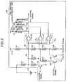
- Fig. 2 is a configuration diagram of the battery-remaining-level display unit 120 shown in Fig. 1.
- a blue LED 121, a green LED 122, and an orange LED 123 respectively display battery remaining level of the secondary battery 105 of the bus power device 100 in the following three operation statuses (1) to (3), using respective (red, green, and orange) colors:
- a switching element 124, a switching element 125, and a switching element 126 are provided in parallel corresponding to the blue LED 121, the green LED 122, and the orange LED 123 respectively.
- the switching element 124 is on/off controlled based on a charge signal which indicates that the bus power device 100 is in the charge status (1), and is turned on when the charge controller 114 (see Fig. 1) inputs the charge signal.
- the switching element 125 is on/off controlled based on an access signal which indicates that the bus power device 100 is in the access status (2), and is turned on when the ATA interface 102 (see Fig. 1) inputs the access signal.
- the switching element 126 is on/off controlled based on a data transfer signal which indicates that the bus power device 100 is in the data transfer status (3), and is turned on when the ATA interface 102 (see Fig. 1) inputs the data transfer signal.
- a resistor 127 and a resistor 128 are present between the secondary battery 105 and the switching element 124.
- the resistor 127 and a resistor 129 are connected to the secondary battery 105.
- a voltage of the resistor 129 is a battery voltage VB of the secondary battery 105.
- One end of a resistor 130 is connected to the switching element 125.
- a resistor 131, a resistor 132, a resistor 133, and a resistor 134 are connected in series, and they are voltage divider resistors that generate threshold voltages at three stages of a threshold voltage VT 1 , a threshold voltage VT 2 ( ⁇ the threshold voltage VT 1 ), and a threshold voltage VT 3 ( ⁇ the threshold voltage VT 2 : when the switching element 126 is on) which are compared with the battery voltage VB respectively.
- the resistors 131, 132, 133, and 134 are applied with a voltage of 3.3 V respectively.
- a comparator 135 compares the battery voltage VB with the threshold voltage VT 1 . When the battery voltage VB exceeds the threshold voltage VT 1 , the comparator 135 turns on the blue LED 121 through a resistor 138, and outputs a full charge signal to the hard disk power source switch 109 (see Fig. 1).
- a comparator 136 compares the battery voltage VB with the threshold voltage VT 2 . When the battery voltage VB exceeds the threshold voltage VT 2 , the comparator 136 turns on the green LED 122 through a resistor 139.
- a comparator 137 compares the battery voltage VB with the threshold voltage VT 3 . When the battery voltage VB is lower than the threshold voltage VT 3 , the comparator 137 turns on the orange LED 123 through a resistor 140.
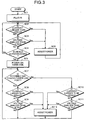
- Fig. 3 is a flowchart for explaining the power assist operation by the bus power device 100 shown in Fig. 1.
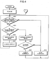
- Fig. 4 is a flowchart for explaining the charge operation by the bus power device 100.
- the USB connector 150 is connected to the high-power USB port 11, and is plugged in. Then, the USB-corresponding device 10 supplies the low power (100 mA/5 V) to each section through the bus power line 151.
- the current/voltage detecting unit 107 detects the current/voltage of the bus power line 151.
- the high-power USB port 11 supplies the low power (100 mA/5 V) to the bus power device 100 during the period from when the USB connector 150 is plugged into the high-power USB port 11 till when the USB-corresponding device 10 acknowledges the bus power device 100. After the USB-corresponding device 10 acknowledges the bus power device 100, the high-power USB port 11 supplies the high power (500 mA/5 V) to the bus power device 100.
- the current/voltage detecting unit 107 determines whether the USB-corresponding device 10 acknowledges the bus power device 100. In this case, the current/voltage detecting unit 107 determines "No" as a result.
- the current/voltage detecting unit 107 determines "Yes" at step SC2.
- the current/voltage detecting unit 107 instructs the power assisting unit 108 to assist the current.
- the current/voltage detecting unit 107 determines "Yes" at step SC3.
- the current/voltage detecting unit 107 instructs the power assisting unit 108 to assist the voltage.
- the USB-corresponding device 10 supplies the high power (500 mA/5 V) to each section through the bus power line 151, and the hard disk 103 is powered on.
- the DC/DC converter 104 supplies a voltage of 3.3 V to the USB/ATA converter 101, so that the USB/ATA converter 101 starts operation.
- the bus power line 151 supplies power to the hard disk 103, so that the hard disk 103 starts operation.
- the current/voltage detecting unit 107 determines whether the USB connector 150 is connected to the high-power USB port 11. The current/voltage detecting unit 107 determines "Yes” as a result in this case.
- the current/voltage detecting unit 107 determines "Yes" at step SC8.
- the current/voltage detecting unit 107 instructs the power assisting unit 108 to assist the current.
- the current/voltage detecting unit 107 determines "Yes" at step SC9.
- the current/voltage detecting unit 107 instructs the power assisting unit 108 to assist the voltage.
- the current/voltage detecting unit 107 determines "No" at step SC7. In this case, the USB-corresponding device 10 supplies the low power (100 mA/5 V) to each section through the bus power line 151.
- the AC/DC adaptor 111 supplies operation power to the bus power line 151 via the power assisting unit 108.
- USB connector 150 when the USB connector 150 is connected to the low-power USB port 12 and also when the AC/DC adaptor 111 is not connected to the DC jack 110, operation power is supplied to the bus power line 151 via the DC/DC converter 106 and the power assisting unit 108 based on a discharge from the secondary battery 105.
- the current/voltage detecting unit 107 determines "Yes" at step SC10.
- the current/voltage detecting unit 107 instructs the power assisting unit 108 to assist the current in a similar manner to that of the above operation.
- the current/voltage detecting unit 107 determines "Yes" at step SC11.
- the current/voltage detecting unit 107 instructs the power assisting unit 108 to assist the voltage in a similar manner to that of the above operation.
- the USB connector 150 is connected to the high-power USB port 11 (or the low-power USB port 12) and is plugged in. Then, at step SD2, the charge controller 114 determines whether the battery voltage of the secondary battery 105 is less than 4.2 V (a full charge).
- the charge mode selector 113 determines at step SD3 whether the AC/DC adaptor 111 is connected to the DC jack 110.
- the charge mode selector 113 selects the normal charge mode at step SD6.
- the charge timing selector 112 determines whether the hard disk 103 is accessed, that is, whether a current consumption is large due to the access.
- the charge timing selector 112 When determine "No” at step SD7, the charge timing selector 112 outputs a charge instruction to the charge controller 114.
- the charge controller 114 supplies the first charge current to the secondary battery 105 in the normal charge mode selected by the charge mode selector 113, to execute the normal charge.
- the first charge current is a part of the current that is supplied from the USB-corresponding device 10 to the bus power line 151 and that flows through the bus power line 151.
- the charge timing selector 112 outputs a charge stop instruction to the charge controller 114.
- the charge controller 114 stops charging the secondary battery 105.
- step SD3 When the AC/DC adaptor 111 is connected to the DC jack 110, the determination result at step SD3 becomes "Yes”.
- step SD4 the charge mode selector 113 selects the rapid charge mode.
- step SD5 the charge controller 114 supplies the second charge current (> the first charge current) to the secondary battery 105 corresponding to the rapid charge mode, thereby executing the rapid charge.
- step SD9 the charge is stopped at step SD9.
- the second charge current is a part of the current that is supplied from both the USB-corresponding device 10 and the AC/DC adaptor 111 to the bus power line 151 and that flows through the bus power line 151.
- the second charge current is larger than the first charge current according to the normal charge. Therefore, based on the rapid charge, the secondary battery 105 can be fully charged in a shorter time than that based on the normal charge.
- the battery remaining level display operation by the battery-remaining-level display unit 120 shown in Fig. 2 is explained next.
- the charge controller 114 inputs a charge signal to the switching element 124 in a state that the secondary battery 105 is charged, in Fig. 2, the switching element 124 is turned on, and the resistor 128 is connected in parallel with the resistor 129. Therefore, the battery voltage VB changes.
- the comparator 135 When the battery voltage VB exceeds the threshold voltage VT 1 , the comparator 135 turns on the blue LED 121, and outputs a full charge signal indicating that the secondary battery 105 is fully charged, to the hard disk power source switch 109 (see Fig. 1). When the blue LED 121 is turned on, a user acknowledges that the secondary battery 105 is fully charged.
- the ATA interface 102 When the ATA interface 102 (see Fig. 1) inputs an access signal to the switching element 125 in the access status, the switching element 125 is turned on, and the resistor 130 is connected in parallel with the resistor 133 and the resistor 134.
- the threshold voltage VT 2 is lower than the threshold voltage VT 1 .
- the comparator 136 turns on the green LED 122.
- the ATA interface 102 (see Fig. 1) inputs a data transfer signal to the switching element 126 in the data transfer status, the switching element 126 is turned on, and the resistor 134 is short-circuited.
- the comparator 137 turns on the orange LED 123.
- the current/voltage detecting unit 107 detects the current/voltage supplied from the USB-corresponding device 10 to the bus power line via the high-power USB port 11 (or the low-power USB port 12) and the USB connector 150.
- the power assisting unit 108 assists the current to the bus power line 151 based on a result of the comparison between the detected current and the threshold current.
- the power assisting unit 108 also assists a voltage as much as the deficient amount to the bus power line 151 based on a result of the comparison between the detected voltage and the threshold voltage. Therefore, overload of the USB-corresponding device 10 due to a current increase or an inoperative state due to a voltage drop can be avoided.
- the power assisting unit 108 assists voltage to the bus power line 151 to compensate for a voltage drop from the USB-corresponding device 10 to the bus power line 151. Therefore, an inoperative state due to the voltage drop attributable to a cable length or a contact resistance can be avoided.
- the first charge current is charged to the secondary battery 105 in the normal charge mode.
- the second charge current larger than the first charge current is rapidly charged to the secondary battery 105. Therefore, needs for a rapid charge to complete charging in a short time can be satisfied.
- the secondary battery 105 supplies power to each section as a main power source through the bus power line 151. Therefore, bus power device 100 can be operated by the low-power USB port 12 without the AC/DC adaptor 111.
- the threshold voltage VT 1 , the threshold voltage VT 2 , and the threshold voltage VT 3 are set at stages according to the operation statuses (the charge status, the access status, and the data transfer status) of each section. Based on a result of comparison between the battery voltage VB of the secondary battery 105 and the threshold voltage, battery remaining level corresponding to the operation status is displayed in the blue LED 121, the green LED 122, and the orange LED 123. Therefore, battery remaining level corresponding to the operation status can be understood.
- a bus power device can be configured to carry out a forced charge to the secondary battery 105 with priority by stopping power supply to each section or stopping its functions.
- An example of this configuration is explained as a second embodiment of the present invention.
- Fig. 5 is a block diagram of a configuration of a bus power device according to the second embodiment.
- like reference numerals as those in Fig. 1 designate like parts, and their explanation is omitted.
- a bus power device 200 shown in the drawing has a forced charge switch 201 additionally, and a charge controller 202 instead of the charge controller 114 shown in Fig. 1.
- the forced charge switch 201 is operated by a user to carry out the forced charge.
- the charge controller 202 has the function of carrying out the normal charge and the rapid charge that the charge controller 114 (see Fig: 1) has, and a function of carrying out the forced charge when the forced charge switch 201 is turned on.
- the USB connector 150 is connected to the high-power USB port 11, and is plugged in.
- the charge controller 202 determines whether the forced charge switch 201 is on. When the determination result is "No", the normal charge or the rapid charge is carried out to the secondary battery 105 at step SD2 and subsequent steps in Fig. 4.
- the charge controller 202 determines "Yes" at step SE2.
- the USB/ATA converter 101 stops the convert function since a reset signal is input following the turning-on of the forced charge switch 201. As a result, the USB/ATA converter 101 lowers power consumption.
- the USB/ATA converter 101 outputs an off signal to the hard disk power source switch 109.
- the hard disk power source switch 109 is turned off, and stops supplying power to the hard disk 103.
- the charge controller 202 determines whether the battery voltage of the secondary battery 105 is less than 4.2 V (full charge), and, in this case, determines "Yes” as a result.
- the charge controller 202 supplies a third charge current to the secondary battery 105 corresponding to a forced charge mode from the forced charge switch 201, thereby executing the forced charge.
- the USB-corresponding device 10 (the AC/DC adaptor 111) supplies the third charge current to the bus power line 151 so that this current flows through the bus power line 151.
- the power saved by the USB/ATA converter 101 and the power not supplied to the hard disk 103 is devoted to the forced charge to the secondary battery 105 as the third charge current. Therefore, among the normal charge and the rapid charge according to the first embodiment, and the above forced charge, the forced charge fully charges the secondary battery 105 in a shortest time.
- the charge controller 202 stops charging the secondary battery 105 at step SE7.
- forced charge is instructed by stopping (or lowering) power supply to the load (the hard disk 103, the USB/ATA converter 101, and the like) that is connected to the bus power line 151, thereby compulsorily charging the third charge current larger than the second charge current to the secondary battery 105. Therefore, needs for a forced charge to complete charging in a shorter time can be satisfied.
- the present invention when the detected voltage is less than the threshold voltage, voltage to the bus power line is assisted to compensate for a voltage drop from the host apparatus to the bus power line. Therefore, there is an effect that an inoperative state due to the voltage drop attributable to a cable length or a contact resistance can be avoided.
- the first charge current is normally charged to the secondary battery.
- the second charge current larger than the first.charge current is rapidly charged to the secondary battery. Therefore, there is an effect that needs for a rapid charge to complete charging in a short time can be satisfied.
- forced charge is instructed by stopping power supply to the load connected to the bus power line, thereby compulsorily charging the third charge current larger than the second charge current to the secondary battery. Therefore, there is an effect that needs for a forced charge to complete charging in a shorter time can be satisfied.
- threshold voltages are set at stages according to the operation statuses of each section. Based on a result of comparison between the battery voltage of the secondary battery and the threshold voltage, battery remaining level corresponding to the operation status is displayed. Therefore, there is an effect that battery remaining level corresponding to the operation status can be understood.
- the bus power device and the power-source control method according to the present invention are suitable for the interface standard of USB, IEEE1934, and the like as the interface that connects a peripheral device to a personal computer.
Landscapes
- Engineering & Computer Science (AREA)
- Theoretical Computer Science (AREA)
- General Engineering & Computer Science (AREA)
- Physics & Mathematics (AREA)
- General Physics & Mathematics (AREA)
- Computer Hardware Design (AREA)
- Charge And Discharge Circuits For Batteries Or The Like (AREA)
- Power Sources (AREA)
Abstract
To include a USB connector (150) that is connected to a
high-power USB port (11) (or a low-power USB port (12)) of a
USB-corresponding device (10) corresponding to a USB interface
standard, a current/voltage detecting unit (107) that detects
current/voltage supplied from the USB-corresponding device (10) to a
bus power line (151) via the high-power USB port (11) (or the
low-power USB port (12)) and the USB connector (150), and a power
assisting unit (108) that assists a current to the bus power line (151)
based on a result of comparison between a current detected by the
current/voltage detecting unit (107) and a threshold current, and assists
a voltage as much as the deficient amount to the bus power line (151)
based on a result of comparison between a detected voltage and a
threshold voltage.
Description
The present invention relates to a bus power device based on
an interface standard of universal serial bus (USB), Institute of
Electrical and Electronics Engineers (IEEE) 1394, and the like. More
particularly, the present invention relates to a bus power device and a
power-source control method that can avoid an inoperative state due to
a voltage drop or the like, figure out a battery remaining level according
to an operation status, and charge the battery quickly.
Recently, as an interface to connect a peripheral device to a
personal computer, the USB interface standard attracts attention. The
USB interface standard has a characteristic that the interface can
connect maximum of 127 USB devices in a tree structure.
Fig. 7 is a block diagram of a configuration of a conventional
bus power device 20. In this drawing, a USB-corresponding device 10
is a personal computer corresponding to the USB interface standard,
and has a high-power USB port 11. A hub 13 has a low-power USB
port 12 that is driven with bus power.
The high-power USB port 11 is connected with a USB connector
(i.e., a USB connector 30 in the drawing) and can supply high power.
The high-power USB port 11 has a basic function as a data input/output
port, and a function of supplying rated power of 2.5 watts (500 mA/5 V)
to the USB device (i.e., the bus power device 20 in the drawing).
The low-power USB port 12 is a low-power port connected with
the USB connector, and has a function as a data input/output port, and
a function of supplying rated power of 0.5 watt (100 mA/5 V) to the USB
device. However, the USB device connected to the low-power USB
port 12 is not driven with low power of 0.5 watt, but is a self-power unit
that is driven with power received from a separate power source.
The bus power device 20 is a hard disk drive unit as one USB
device, and is driven with high power (2.5 watts (500 mA/5 V)) supplied
from the USB-corresponding device 10 via the USB connector 30
connected to the high-power USB port 11.
The USB connector 30 is based on the USB interface standard,
and is connected to the high-power USB port 11 when the bus power
device 20 is used. The USB connector 30 is also connected to a bus
power line 31 to supply power to each section, a data line 32, a ground
(GND) line, a shield line, and the like.
A USB/AT attachment (USB/ATA) converter 21 has a function of
converting data of the USB interface standard input through a data line
32 into data of an ATA interface standard, and outputting the converted
data to a hard disk 23 via an ATA interface 22.
The hard disk 23 is a large-capacity recording medium which is
rotatably driven with power supplied through the bus power line 31 to
read/write data.
The USB/ATA converter 21 has a function of converting the data
of the ATA interface standard read from the hard disk 23 and input via
the ATA interface 22, into data of the USB interface standard, and
outputting the converted data to the data line 32.
A voltage adjustor 24 adjusts a voltage of 5 V supplied through
the bus power line 31 into a voltage of 3.3 V, and supplies this voltage
to the USB/ATA converter 21.
The operation by the bus power device 20 is explained with
reference to a flowchart shown in Fig. 8. At step SA1 in the drawing,
the USB connector 30 is connected to the high-power USB port 11, and
is plugged in. At step SA2, the USB-corresponding device 10
acknowledges the bus power device 20.
At step SA3, it is determined whether the USB connector 30 is
connected to the high-power USB port 11. In this case, the
determination result is "Yes". At step SA4, the USB-corresponding
device 10 supplies the high power (500 mA/5 V) to the voltage adjustor
24 and the hard disk 23 through the bus power line 31.
As a result, at step SA5, the voltage adjustor 24 supplies the
voltage of 3.3 V to the USB/ATA converter 21, so that the USB/ATA
converter 21 starts operation and the hard disk 23 also starts operation.
On the other hand, when the determination result at step SA3 is
"No", that is, when the USB connector 30 is connected to the low-power
USB port 12, the USB-corresponding device 10 supplies only the low
power (100 mA/5 V) to each section of the bus power device 20.
Therefore, at step SA6, the bus power device 20 is unusable.
According to the bus power device 20 shown in Fig. 7,
depending on the operation condition, immediately after the USB
connector 30 is connected to the USB-corresponding device 10, an
inrush current flows through the bus power line 31 at the initial rotation
of the hard disk 23. This has a problem in that the current supplied
from the USB-corresponding device 10 to the bus power device 20 may
exceed a predetermined value (500 mA), leading to a malfunction or an
operation failure.
To solve this problem, the conventional bus power device
employs a current assisting system by having a secondary battery.
When the current that flows through the bus power line 31 exceeds a
predetermined value, the secondary battery countervails an overcurrent,
or assists to decrease the current that is supplied from the high-power
USB port 11 to the bus power device 20.
Fig. 9 is a block diagram of a configuration of a conventional
bus power device 40 according to the current assisting system. In the
drawing, like reference numerals as those in Fig. 7 designate like parts,
and their explanation is omitted.
In the bus power device 40 in the drawing, a secondary battery
41 is a lithium ion battery, an alkali battery, a nickel cadmium battery, or
the like that can be repetitively charged and discharged. When the
current flowing through the bus power line 31 exceeds a predetermined
value, the secondary battery 41 supplies an overcurrent to each section
through the bus power line 31.
A current detector 42 detects a current that flows through the
bus power line 31. An micro processing unit (MPU) 43 has a function
of controlling the current assist based on the result of the current
detection by the current detector 42, a function of controlling a charge
to the secondary battery 41, a function of controlling a power supply to
the hard disk 23, a function of controlling a display of a battery
remaining level, a function of monitoring a status of the USB/ATA
converter 21, and the like.
A hard disk power source switch 44 is present between the bus
power line 31 and the hard disk 23, and has a function of turning on/off
a power supply to the hard disk 23 under the control of the MPU 43. A
charger 45 is present between the bus power line 31 and the secondary
battery 41, and has a function of charging a current flowing through the
bus power line 31 to the secondary battery 41 under the control of the
MPU 43.
A current assisting unit 46 is present between the secondary
battery 41 and the bus power line 31, and has a current assisting
function of supplying an overcurrent from the secondary battery 41 to
the bus power line 31 under the control of the MPU 43 when a current
exceeding a predetermined value flows to the bus power line 31.
A battery-remaining-level display unit 47 displays a battery
remaining level of the secondary battery 41 by lighting/flickering a light
emitting diode (LED) under the control of the MPU 43. Specifically,
when the battery voltage of the secondary battery 41 exceeds a
threshold value, the LED lights up to inform a user that the battery
remaining level is sufficient. On the other hand, when the battery
voltage of the secondary battery 41 becomes equal to or lower than the
threshold value, the LED flickers to inform the user that there is only
small room in the battery remaining level.
In the above configuration, when the USB connector 30 is
connected to the high-power USB port 11 and is plugged in, the
USB-corresponding device 10 acknowledges the bus power device 40.
As a result, the USB-corresponding device 10 supplies the high
power (500 mA/5 V) to each section through the bus power line 31 to
activate each section. Specifically, the voltage adjustor 24 supplies a
voltage of 3.3 V to the USB/ATA converter 21, so that the USB/ATA
converter 21 starts operation. When the hard disk power source
switch 44 is turned on under the control of the MPU 43, the bus power
line 31 supplies power to the hard disk 23, so that the hard disk 23
starts operation.
When an inrush current flows through the bus power line 31 due
to the initial rotation of the hard disk 23 and when this current exceeds
a predetermined value, a current assist is carried out. In other words,
when the current detected by the current detector 42 exceeds the
predetermined value, the MPU 43 instructs the current assisting unit 46
to assist the current.
As a result, the current assisting unit 46 discharges the
secondary battery 41, and supplies the current from the secondary
battery 41 to the bus power line 31. Accordingly, the current detector
42 detects that the current becomes equal to or smaller than the
predetermined value, because the current is smaller by the current
discharged from the secondary battery 41.
When the current detected by the current detector 42 is equal to
or smaller than the predetermined value, the current assisting unit 46
does not need to assist the current, and therefore, the MPU 43 outputs
a charge pulse to the charger 45.
Therefore, the charger 45 supplies a part of the current from the
bus power line 31 to the secondary battery 41 to charge the secondary
battery 41. The MPU 43 makes the battery-remaining-level display
unit 47 display a battery remaining level of the secondary battery 41
based on a result of monitoring the battery voltage.
When the USB connector 30 is connected to the low-power USB
port 12, the USB-corresponding device 10 supplies only the low power
(100 mA/5 V) to each section of the bus power device 40. Therefore,
the bus power device 40 is unusable.
Fig. 10 is a block diagram of a configuration of a conventional
bus power device 50. In the drawing, like reference numerals as those
in Fig. 9 designate like parts, and their explanation is omitted. When
the USB connector 30 is connected to the low-power USB port 12, the
bus power device 50 in the drawing receives high power from a
separate power source and is driven.
The bus power device 50 additionally has a direct current (DC)
jack 51 and a switcher 52. The DC jack 51 is a terminal that connects
an alternating current/direct current (AC/DC) adaptor (not shown) as a
separate power source. The DC jack 51 is connected to the bus power
line 31 via the switcher 52.
The AC/DC adaptor converts an alternating current to a direct
current, and generates a DC voltage/current. The switcher 52 has a
function of switching the connection destination of the bus power line
31 to the USB connector 30 or the DC jack 51.
The operation by the bus power device 50 is explained with
reference to a flowchart shown in Fig. 11. In the above configuration,
when the AC/DC adaptor (not shown) is connected to the DC jack 51 in
a state that the switcher 52 switches over to the DC jack 51, at step
SB1 shown in Fig. 11, the AC/DC adaptor supplies the high power (500
mA/5 V) to each section via the DC jack 51, the switcher 52, and the
bus power line 31, so that each section is activated.
Specifically, the voltage adjustor 24 supplies a voltage of 3.3 V
to the USB/ATA converter 21, so that the USB/ATA converter starts
operation. When the hard disk power source switch 44 is turned on
under the control of the MPU 43, the bus power line 31 supplies power
to the hard disk 23, so that the hard disk 23 is powered on.
When the USB connector 30 is connected to the low-power USB
port 12 and is plugged in at step SB2, the USB-corresponding device
10 acknowledges the bus power device 50 at step SB3. At step SB4,
the bus power device 50 starts the operation.
As described above, in the bus power device 40 shown in Fig. 9,
the current detector 42 detects a current that flows through the bus
power line 31. When the current exceeds a predetermined value, the
secondary battery 41 assists the current according to the current
assisting system.
In Fig. 9, when a connector contact resistance from the
high-power USB port 11 to a unit to be driven (such as the hard disk
23) is large or when a cable is long, a large voltage drop occurs.
For example, assume that the high-power USB port 11 has a
voltage of 5 V, and the operation guarantee voltage of the hard disk 23
is 4.75 to 5.25 V. In this case, when the voltage drops in excess of
0.25 V, a voltage supplied to the hard disk 23 becomes less than the
operation guarantee voltage of 4.75 (5 to 0.25) V. As a result, the hard
disk 23 does not operate.
However, according to the current assisting system in the bus
power device 40, only the current that flows through the bus power line
31 is detected. Therefore, the inoperative state due to the voltage
drop cannot be avoided.
According to the conventional bus power device 40, the load
(the battery voltage) of the secondary battery 41 changes depending on
the operation status (charging, access to the hard disk 23, or data
transfer) of the bus power device 40. Despite this change, the bus
power device 40 compares the battery voltage of the secondary battery
41 with one threshold value, and makes the battery-remaining-level
display unit 47 display the battery remaining level based on a result of
this comparison. Therefore, an accurate battery remaining level
cannot be understood.
According to the conventional bus power device 40, the charger
45 charges a constant current to the secondary battery 41. Therefore,
even when it is necessary to charge in a short time, a quick charging
cannot be achieved.
When the conventional bus power device 50 shown in Fig. 10 is
connected to the low-power USB port 12, a separate power source (the
AC/DC adapter) is essential. Therefore, the bus power device 50
cannot be used without the separate power source.
It is an object of the present invention to provide a bus power
device and a power-source control method that can avoid an
inoperative state due to a voltage drop, understanding a battery
remaining level according to an operation status, and charge quickly.
A bus power device according to one aspect of the present
invention includes a connector that is connected to a port of a host
apparatus compliant with a predetermined interface standard; a
current/voltage detecting unit that detects a current/voltage supplied
from the host apparatus to a bus power line via the port and the
connector; and a power assisting unit that assists a current to the bus
power line based on a result of comparison between the current
detected by the current/voltage detecting unit and a threshold current,
and assists a voltage to the bus power line by an amount of based on a
result of comparison between the voltage detected by the
current/voltage detecting unit and a threshold voltage.
According to the present invention, current/voltage supplied
from a host apparatus to the bus power line via the port and the
connector is detected. A current to the bus power line is assisted
based on a result of comparison between the detected current and the
threshold current. The voltage as much as the deficient amount is
assisted to the bus power line based on a result of comparison between
the detected voltage and the threshold voltage. Therefore, there is an
effect that overload of the host apparatus due to a current increase or
an inoperative state due to a voltage drop can be avoided.
First and second embodiments according to the present
invention will be explained in detail with reference to the accompanying
drawings.
Fig. 1 is a block diagram of a configuration of a bus power
device according to a first embodiment of the present invention. In the
drawing, like reference numerals as those in Fig. 9 designate like parts,
and their explanation is omitted. In the drawing, a bus power device
100 is provided in place of the bus power device 40 shown in Fig. 9.
The bus power device 100 is a hard disk drive unit as one USB
device, and is driven with high power (2.5 watts (500 mA/5 V)) supplied
from the USB-corresponding device 10 via a USB connector 150
connected to the high-power USB port 11 or supplied from an AC/DC
adaptor 111 described later.
The USB connector 150 is based on the USB interface standard,
and is connected to the high-power USB port 11 during a normal use of
the bus power device 100. When the USB connector 150 is connected
to the low-power USB port 12, and even when the AC/DC adaptor 111
is not present, the bus power device 100 can operate using a
secondary battery 105.
The USB connector 150 is connected to a bus power line 151 to
supply power to each section, a data line 152, a GND line, a shield line,
and the like.
A USB/ATA converter 101 has a function of converting data of
the USB interface standard input through the data line 152 into data of
the ATA interface standard, and outputting the converted data to a hard
disk 103 via an ATA interface 102.
The hard disk 103 is a large-capacity recording medium which is
rotatably driven with power supplied through the bus power line 151 to
read/write data.
The USB/ATA converter 101 has a function of converting the
data of the ATA interface standard read from the hard disk 103 and
input via the ATA interface 102, into data of the USB interface standard,
and outputting the converted data to the data line 152.
A DC/DC converter 104 converts a voltage of 5 V supplied from
the bus power line 151 into a voltage of 3.3 V, and supplies this voltage
of 3.3 V to the USB/ATA converter 101.
The secondary battery 105 is a lithium ion battery, an alkali
battery, a nickel cadmium battery, or the like that can be repetitively
charged and discharged. When a current that flows through the bus
power line 151 exceeds a predetermined value, the secondary battery
105 supplies an overcurrent to each section. When a voltage of the
bus power line 151 is equal to or smaller than a predetermined value,
the secondary battery 105 supplies a voltage as much as the deficient
amount to the bus power line 151.
When the USB connector 150 is connected to the low-power
USB port 12 and also when the AC/DC adaptor 111 explained later is
not connected, the secondary battery 105 functions as a main power
source, and supplies power to each section. A battery voltage (a rated
value) of the secondary battery 105 is 4.2 to 3 V. The DC/DC
converter 106 has a function of raising the battery voltage of the
secondary battery 105 to 5 V.
A current/voltage detecting unit 107 detects a current that flows
through the bus power line 151, and detects a voltage of the bus power
line 151. When the current/voltage detecting unit 107 detects that the
current exceeds a threshold current (for example, 100 mA or 500 mA),
the current/voltage detecting unit 107 makes a power assisting unit 108
supply an overcurrent from the secondary battery 105 (the AC/DC
adaptor 111 explained later) to the bus power line 151.
When the current/voltage detecting unit 107 detects that the
voltage is less than a threshold voltage (for example, 4.75 V), the
current/voltage detecting unit 107 makes the power assisting unit 108
supply a voltage from the DC/DC converter 106 (the secondary battery
105) or the AC/DC adaptor 111 to the bus power line 151, thereby
raising the voltage of the bus power line 151.
The power assisting unit 108 has a function of assisting power
based on both the current assist and the voltage assist.
A hard disk power source switch 109 is present between the bus
power line 151 and the hard disk 103, and has a function of turning
on/off a power supply to the hard disk 103. A DC jack 110 is a terminal
that connects the AC/DC adaptor 111 as a separate power source.
The DC jack 110 is connected to the power assisting unit 108 or the
like.
The AC/DC adaptor 111 converts an alternating current to a
direct current, and generates a DC voltage/current. A charge timing
selector 112 has a function of selecting a timing of charging the
secondary battery 105.
A charge mode selector 113 selects a rapid charge mode when
the AC/DC adaptor 111 is connected to the DC jack 110, and selects a
normal charge mode when the AC/DC adaptor 111 is not connected to
the DC jack 110. In the rapid charge mode, a charge current is larger
than that in the normal charge mode, and therefore, a charge time from
a start of charging till the charge becomes full can be shortened,
thereby making it possible to charge rapidly.
A charge controller 114 controls charging to the secondary
battery 105 based on a charge timing from the charge timing selector
112 and a charge mode from the charge mode selector 113. The
charge controller 114 has the normal charge mode of charging a first
charge current, and the rapid charge mode of rapidly charging a second
charge current (> the first charge current).
The battery-remaining-level display unit 120 changes a
threshold voltage at three stages according to the operation status of
the bus power device 100, and displays a battery remaining level based
on a result of comparison between the threshold voltage and the
battery voltage of the secondary battery 105.
Fig. 2 is a configuration diagram of the battery-remaining-level
display unit 120 shown in Fig. 1. In the drawing, a blue LED 121, a
green LED 122, and an orange LED 123 respectively display battery
remaining level of the secondary battery 105 of the bus power device
100 in the following three operation statuses (1) to (3), using respective
(red, green, and orange) colors:
A switching element 124, a switching element 125, and a
switching element 126 are provided in parallel corresponding to the
blue LED 121, the green LED 122, and the orange LED 123
respectively.
The switching element 124 is on/off controlled based on a
charge signal which indicates that the bus power device 100 is in the
charge status (1), and is turned on when the charge controller 114 (see
Fig. 1) inputs the charge signal.
The switching element 125 is on/off controlled based on an
access signal which indicates that the bus power device 100 is in the
access status (2), and is turned on when the ATA interface 102 (see Fig.
1) inputs the access signal.
The switching element 126 is on/off controlled based on a data
transfer signal which indicates that the bus power device 100 is in the
data transfer status (3), and is turned on when the ATA interface 102
(see Fig. 1) inputs the data transfer signal.
A resistor 127 and a resistor 128 are present between the
secondary battery 105 and the switching element 124. The resistor
127 and a resistor 129 are connected to the secondary battery 105. In
the drawing, a voltage of the resistor 129 is a battery voltage VB of the
secondary battery 105. One end of a resistor 130 is connected to the
switching element 125.
A resistor 131, a resistor 132, a resistor 133, and a resistor 134
are connected in series, and they are voltage divider resistors that
generate threshold voltages at three stages of a threshold voltage VT1,
a threshold voltage VT2 (< the threshold voltage VT1), and a threshold
voltage VT3 (< the threshold voltage VT2: when the switching element
126 is on) which are compared with the battery voltage VB respectively.
The resistors 131, 132, 133, and 134 are applied with a voltage of 3.3 V
respectively.
A comparator 135 compares the battery voltage VB with the
threshold voltage VT1. When the battery voltage VB exceeds the
threshold voltage VT1, the comparator 135 turns on the blue LED 121
through a resistor 138, and outputs a full charge signal to the hard disk
power source switch 109 (see Fig. 1).
A comparator 136 compares the battery voltage VB with the
threshold voltage VT2. When the battery voltage VB exceeds the
threshold voltage VT2, the comparator 136 turns on the green LED 122
through a resistor 139. A comparator 137 compares the battery
voltage VB with the threshold voltage VT3. When the battery voltage
VB is lower than the threshold voltage VT3, the comparator 137 turns
on the orange LED 123 through a resistor 140.
The operation by the bus power device according to the first
embodiment is explained next with reference to flowcharts shown in Fig.
3 and Fig. 4. Fig. 3 is a flowchart for explaining the power assist
operation by the bus power device 100 shown in Fig. 1. Fig. 4 is a
flowchart for explaining the charge operation by the bus power device
100.
At step SC1 shown in Fig. 3, the USB connector 150 is
connected to the high-power USB port 11, and is plugged in. Then,
the USB-corresponding device 10 supplies the low power (100 mA/5 V)
to each section through the bus power line 151. The current/voltage
detecting unit 107 detects the current/voltage of the bus power line
151.
According to the USB interface standard, the high-power USB
port 11 supplies the low power (100 mA/5 V) to the bus power device
100 during the period from when the USB connector 150 is plugged into
the high-power USB port 11 till when the USB-corresponding device 10
acknowledges the bus power device 100. After the
USB-corresponding device 10 acknowledges the bus power device 100,
the high-power USB port 11 supplies the high power (500 mA/5 V) to
the bus power device 100.
At step SC2, the current/voltage detecting unit 107 determines
whether the current that flows through the bus power line 151 exceeds
the threshold current (=100 mA). In this case, the current/voltage
detecting unit 107 determines "No" as a result.
At step SC3, the current/voltage detecting unit 107 determines
whether the voltage of the bus power line 151 is less than the threshold
voltage (=4.75 V). In this case, the current/voltage detecting unit 107
determines "No" as a result. At step SC4, the current/voltage
detecting unit 107 determines whether the USB-corresponding device
10 acknowledges the bus power device 100. In this case, the
current/voltage detecting unit 107 determines "No" as a result.
When the current that flows through the bus power line 151
exceeds the threshold current (=100 mA), the current/voltage detecting
unit 107 determines "Yes" at step SC2. At step SC5, the
current/voltage detecting unit 107 instructs the power assisting unit 108
to assist the current.
As a result, the power assisting unit 108 supplies the current
from the DC/DC converter 106 (the secondary battery 105) to the bus
power line 151. Accordingly, the current/voltage detecting unit 107
detects that the current is smaller by as much as the current from the
DC/DC converter 106 (the secondary battery 105). The current
becomes smaller than the threshold current (=100 mA).
When the voltage of the bus power line 151 becomes less than
the threshold voltage (=4.75 V), the current/voltage detecting unit 107
determines "Yes" at step SC3. At step SC5, the current/voltage
detecting unit 107 instructs the power assisting unit 108 to assist the
voltage.
As a result, the power assisting unit 108 supplies the voltage
from the DC/DC converter 106 (the secondary battery 105) to the bus
power line 151. Accordingly, the current/voltage detecting unit 107
detects that the voltage increases due to the voltage from the DC/DC
converter 106 (the secondary battery 105). The voltage becomes
equal to or higher than the threshold voltage (=4.75 V).
When the USB-corresponding device 10 acknowledges the bus
power device 100, the determination at step SC4 becomes "Yes".
As a result, at step SC6, the USB-corresponding device 10
supplies the high power (500 mA/5 V) to each section through the bus
power line 151, and the hard disk 103 is powered on.
Specifically, the DC/DC converter 104 supplies a voltage of 3.3
V to the USB/ATA converter 101, so that the USB/ATA converter 101
starts operation. When the USB/ATA converter 101 turns on the hard
disk power source switch 109, the bus power line 151 supplies power to
the hard disk 103, so that the hard disk 103 starts operation.
At step SC7, the current/voltage detecting unit 107 determines
whether the USB connector 150 is connected to the high-power USB
port 11. The current/voltage detecting unit 107 determines "Yes" as a
result in this case. At step SC8, the current/voltage detecting unit 107
determines whether the current that flows through the bus power line
151 exceeds the threshold current (=500 mA). In this case, the
current/voltage detecting unit 107 determines "No" as a result.
At step SC9, the current/voltage detecting unit 107 determines
whether the voltage of the bus power line 151 is less than the threshold
voltage (=4.75 V). In this case, the current/voltage detecting unit 107
determines "No" as a result. Thereafter, the processing at step SC7 to
step SC9 is repeated.
When an inrush current flows through the bus power line 151
due to the initial rotation of the hard disk 103 and also when the current
exceeds the threshold current (=500 mA), the current/voltage detecting
unit 107 determines "Yes" at step SC8. At step SC12, the
current/voltage detecting unit 107 instructs the power assisting unit 108
to assist the current.
As a result, the power assisting unit 108 supplies the current
from the DC/DC converter 106 (the secondary battery 105) to the bus
power line 151. Accordingly, the current/voltage detecting unit 107
detects that the current is smaller by as much as the current from the
DC/DC converter 106 (the secondary battery 105). The current
becomes equal to or smaller than the threshold current (=500 mA).
When a voltage drop is large due to a contact resistance or a
cable length from the high-power USB port 11 to a subject to be driven
(the hard disk 103 or the like), the voltage of the bus power line 151
becomes less than the threshold voltage (=4.75 V). Therefore, the
current/voltage detecting unit 107 determines "Yes" at step SC9. At
step SC12, the current/voltage detecting unit 107 instructs the power
assisting unit 108 to assist the voltage.
As a result, the power assisting unit 108 supplies the voltage
from the DC/DC converter 106 (the secondary battery 105) to the bus
power line 151. Accordingly, the current/voltage detecting unit 107
detects that the voltage increases due to the voltage from the DC/DC
converter 106 (the secondary battery 105). The voltage becomes
equal to or higher than the threshold voltage (=4.75 V).
When the USB connector 150 is connected to the low-power
USB port 12, the current/voltage detecting unit 107 determines "No" at
step SC7. In this case, the USB-corresponding device 10 supplies the
low power (100 mA/5 V) to each section through the bus power line
151.
When the USB connector 150 is connected to the low-power
USB port 12 and also when the AC/DC adaptor 111 is connected to the
DC jack 110, the AC/DC adaptor 111 supplies operation power to the
bus power line 151 via the power assisting unit 108.
On the other hand, when the USB connector 150 is connected
to the low-power USB port 12 and also when the AC/DC adaptor 111 is
not connected to the DC jack 110, operation power is supplied to the
bus power line 151 via the DC/DC converter 106 and the power
assisting unit 108 based on a discharge from the secondary battery
105.
At step SC10, the current/voltage detecting unit 107 determines
whether the current that flows through the bus power line 151 exceeds
the threshold current (=100 mA). In this case, the current/voltage
detecting unit 107 determines "No" as a result.
At step SC11, the current/voltage detecting unit 107 determines
whether the voltage of the bus power line 151 is less than the threshold
voltage (=4.75 V). In this case, the current/voltage detecting unit 107
determines "No" as a result. Thereafter, the processing at step SC7,
step SC10, and step SC11 is repeated.
When an inrush current flows through the bus power line 151
due to the initial rotation of the hard disk 103 and also when the current
exceeds the threshold current (=100 mA), the current/voltage detecting
unit 107 determines "Yes" at step SC10. At step SC12, the
current/voltage detecting unit 107 instructs the power assisting unit 108
to assist the current in a similar manner to that of the above operation.
When a voltage drop is large due to a contact resistance or a
cable length from the low-power USB port 12 to a subject to be driven
(the hard disk 103 or the like), the voltage of the bus power line 151
becomes less than the threshold voltage (=4.75 V). Therefore, the
current/voltage detecting unit 107 determines "Yes" at step SC11. At
step SC12, the current/voltage detecting unit 107 instructs the power
assisting unit 108 to assist the voltage in a similar manner to that of the
above operation.
The charge operation by the bus power device 100 is explained
next with reference to the flowchart shown in Fig. 4. At step SD1
shown in the drawing, the USB connector 150 is connected to the
high-power USB port 11 (or the low-power USB port 12) and is plugged
in. Then, at step SD2, the charge controller 114 determines whether
the battery voltage of the secondary battery 105 is less than 4.2 V (a
full charge).
When determined "Yes" at step SD2 is, the charge mode
selector 113 determines at step SD3 whether the AC/DC adaptor 111 is
connected to the DC jack 110.
When determined "No" at step SD3, the charge mode selector
113 selects the normal charge mode at step SD6. At step SD7, the
charge timing selector 112 determines whether the hard disk 103 is
accessed, that is, whether a current consumption is large due to the
access.
When determine "No" at step SD7, the charge timing selector
112 outputs a charge instruction to the charge controller 114. At step
SD8, the charge controller 114 supplies the first charge current to the
secondary battery 105 in the normal charge mode selected by the
charge mode selector 113, to execute the normal charge. The first
charge current is a part of the current that is supplied from the
USB-corresponding device 10 to the bus power line 151 and that flows
through the bus power line 151.
On the other hand, when determined "Yes" at step SD7, the
charge timing selector 112 outputs a charge stop instruction to the
charge controller 114. At step SD9, the charge controller 114 stops
charging the secondary battery 105.
When the AC/DC adaptor 111 is connected to the DC jack 110,
the determination result at step SD3 becomes "Yes". At step SD4, the
charge mode selector 113 selects the rapid charge mode. At step SD5,
the charge controller 114 supplies the second charge current (> the first
charge current) to the secondary battery 105 corresponding to the rapid
charge mode, thereby executing the rapid charge. When determined
"No" at step SD2, the charge is stopped at step SD9.
The second charge current is a part of the current that is
supplied from both the USB-corresponding device 10 and the AC/DC
adaptor 111 to the bus power line 151 and that flows through the bus
power line 151. The second charge current is larger than the first
charge current according to the normal charge. Therefore, based on
the rapid charge, the secondary battery 105 can be fully charged in a
shorter time than that based on the normal charge.
The battery remaining level display operation by the
battery-remaining-level display unit 120 shown in Fig. 2 is explained
next. When the charge controller 114 (see Fig. 1) inputs a charge
signal to the switching element 124 in a state that the secondary
battery 105 is charged, in Fig. 2, the switching element 124 is turned on,
and the resistor 128 is connected in parallel with the resistor 129.
Therefore, the battery voltage VB changes.
When the battery voltage VB exceeds the threshold voltage VT1,
the comparator 135 turns on the blue LED 121, and outputs a full
charge signal indicating that the secondary battery 105 is fully charged,
to the hard disk power source switch 109 (see Fig. 1). When the blue
LED 121 is turned on, a user acknowledges that the secondary battery
105 is fully charged.
When the ATA interface 102 (see Fig. 1) inputs an access signal
to the switching element 125 in the access status, the switching
element 125 is turned on, and the resistor 130 is connected in parallel
with the resistor 133 and the resistor 134. The threshold voltage VT2
is lower than the threshold voltage VT1. When the battery voltage VB
exceeds the threshold voltage VT2, the comparator 136 turns on the
green LED 122.
When the ATA interface 102 (see Fig. 1) inputs a data transfer
signal to the switching element 126 in the data transfer status, the
switching element 126 is turned on, and the resistor 134 is
short-circuited. When the battery voltage VB becomes lower than the
threshold voltage VT3, the comparator 137 turns on the orange LED
123.
As explained above, according to the first embodiment, the
current/voltage detecting unit 107 detects the current/voltage supplied
from the USB-corresponding device 10 to the bus power line via the
high-power USB port 11 (or the low-power USB port 12) and the USB
connector 150. The power assisting unit 108 assists the current to the
bus power line 151 based on a result of the comparison between the
detected current and the threshold current. The power assisting unit
108 also assists a voltage as much as the deficient amount to the bus
power line 151 based on a result of the comparison between the
detected voltage and the threshold voltage. Therefore, overload of the
USB-corresponding device 10 due to a current increase or an
inoperative state due to a voltage drop can be avoided.
According to the first embodiment, when the current/voltage
detecting unit 107 detects that the voltage is less than a threshold
voltage, the power assisting unit 108 assists voltage to the bus power
line 151 to compensate for a voltage drop from the USB-corresponding
device 10 to the bus power line 151. Therefore, an inoperative state
due to the voltage drop attributable to a cable length or a contact
resistance can be avoided.
According to the first embodiment, when the AC/DC adaptor 111
as a separate power source is not connected to the bus power line 151,
the first charge current is charged to the secondary battery 105 in the
normal charge mode. When the AC/DC adaptor 111 is connected to
the bus power line 151, the second charge current larger than the first
charge current is rapidly charged to the secondary battery 105.
Therefore, needs for a rapid charge to complete charging in a short
time can be satisfied.
According to the first embodiment, when the USB connector 150
is connected to the low-power USB port 12 and also when the AC/DC
adaptor 111 is not connected to the DC jack 110, the secondary battery
105 supplies power to each section as a main power source through
the bus power line 151. Therefore, bus power device 100 can be
operated by the low-power USB port 12 without the AC/DC adaptor 111.
According to the first embodiment, as shown in Fig. 2, the
threshold voltage VT1, the threshold voltage VT2, and the threshold
voltage VT3 are set at stages according to the operation statuses (the
charge status, the access status, and the data transfer status) of each
section. Based on a result of comparison between the battery voltage
VB of the secondary battery 105 and the threshold voltage, battery
remaining level corresponding to the operation status is displayed in
the blue LED 121, the green LED 122, and the orange LED 123.
Therefore, battery remaining level corresponding to the operation
status can be understood.
In the first embodiment, a configuration example of rapidly
charging the secondary battery 105 has been explained. When a more
rapid charge is necessary, a bus power device can be configured to
carry out a forced charge to the secondary battery 105 with priority by
stopping power supply to each section or stopping its functions. An
example of this configuration is explained as a second embodiment of
the present invention.
Fig. 5 is a block diagram of a configuration of a bus power
device according to the second embodiment. In the drawing, like
reference numerals as those in Fig. 1 designate like parts, and their
explanation is omitted. A bus power device 200 shown in the drawing
has a forced charge switch 201 additionally, and a charge controller
202 instead of the charge controller 114 shown in Fig. 1.
The forced charge switch 201 is operated by a user to carry out
the forced charge. The charge controller 202 has the function of
carrying out the normal charge and the rapid charge that the charge
controller 114 (see Fig: 1) has, and a function of carrying out the forced
charge when the forced charge switch 201 is turned on.
The charge operation by the bus power device 200 shown in Fig.
5 is explained with reference to a flowchart shown in Fig. 6. At step
SE1 shown in the drawing, the USB connector 150 is connected to the
high-power USB port 11, and is plugged in.
At step SE2, the charge controller 202 determines whether the
forced charge switch 201 is on. When the determination result is "No",
the normal charge or the rapid charge is carried out to the secondary
battery 105 at step SD2 and subsequent steps in Fig. 4.
When the forced charge switch 201 is on, the charge controller
202 determines "Yes" at step SE2. At step SE3, the USB/ATA
converter 101 stops the convert function since a reset signal is input
following the turning-on of the forced charge switch 201. As a result,
the USB/ATA converter 101 lowers power consumption.
At step SE4, the USB/ATA converter 101 outputs an off signal to
the hard disk power source switch 109. As a result, the hard disk
power source switch 109 is turned off, and stops supplying power to the
hard disk 103.
At step SE5, the charge controller 202 determines whether the
battery voltage of the secondary battery 105 is less than 4.2 V (full
charge), and, in this case, determines "Yes" as a result.
At step SE6, the charge controller 202 supplies a third charge
current to the secondary battery 105 corresponding to a forced charge
mode from the forced charge switch 201, thereby executing the forced
charge. The USB-corresponding device 10 (the AC/DC adaptor 111)
supplies the third charge current to the bus power line 151 so that this
current flows through the bus power line 151.
The power saved by the USB/ATA converter 101 and the power
not supplied to the hard disk 103 is devoted to the forced charge to the
secondary battery 105 as the third charge current. Therefore, among
the normal charge and the rapid charge according to the first
embodiment, and the above forced charge, the forced charge fully
charges the secondary battery 105 in a shortest time.
When determined "Yes" at step SE5 due to the forced charge,
the charge controller 202 stops charging the secondary battery 105 at
step SE7.
As explained above, according to the second embodiment,
forced charge is instructed by stopping (or lowering) power supply to
the load (the hard disk 103, the USB/ATA converter 101, and the like)
that is connected to the bus power line 151, thereby compulsorily
charging the third charge current larger than the second charge current
to the secondary battery 105. Therefore, needs for a forced charge to
complete charging in a shorter time can be satisfied.
While the first and the second embodiments of the present
invention are described in detail with reference to the accompanying
drawings, specific examples of the configuration are not limited thereto,
and various design changes within the scope of the appended claims
are also included in the invention.
As explained above, according to the present invention,
current/voltage supplied from a host apparatus to the bus power line via
the port and the connector is detected. A current to the bus power line
is assisted based on a result of comparison between the detected
current and the threshold current. Voltage as much as the deficient
amount is assisted to the bus power line based on a result of
comparison between the detected voltage and the threshold voltage.
Therefore, there is an effect that overload of the host apparatus due to
a current increase or an inoperative state due to a voltage drop can be
avoided.
Furthermore, according to the present invention, when the
detected voltage is less than the threshold voltage, voltage to the bus
power line is assisted to compensate for a voltage drop from the host
apparatus to the bus power line. Therefore, there is an effect that an
inoperative state due to the voltage drop attributable to a cable length
or a contact resistance can be avoided.
Moreover, according to the present invention, when a separate
power source is not connected to the bus power line, the first charge
current is normally charged to the secondary battery. When a separate
power source is connected to the bus power line, the second charge
current larger than the first.charge current is rapidly charged to the
secondary battery. Therefore, there is an effect that needs for a rapid
charge to complete charging in a short time can be satisfied.
Furthermore, according to the present invention, forced charge
is instructed by stopping power supply to the load connected to the bus
power line, thereby compulsorily charging the third charge current
larger than the second charge current to the secondary battery.
Therefore, there is an effect that needs for a forced charge to complete
charging in a shorter time can be satisfied.
Moreover, according to the present invention, threshold voltages
are set at stages according to the operation statuses of each section.
Based on a result of comparison between the battery voltage of the
secondary battery and the threshold voltage, battery remaining level
corresponding to the operation status is displayed. Therefore, there is
an effect that battery remaining level corresponding to the operation
status can be understood.
As described above, the bus power device and the
power-source control method according to the present invention are
suitable for the interface standard of USB, IEEE1934, and the like as
the interface that connects a peripheral device to a personal computer.
Claims (16)
- A bus power device comprising:a connector that is connected to a port of a host apparatus compliant with a predetermined interface standard;a current/voltage detecting unit that detects a current/voltage supplied from the host apparatus to a bus power line via the port and the connector; anda power assisting unit that assists a current to the bus power line based on a result of comparison between the current detected by the current/voltage detecting unit and a threshold current, and assists a voltage to the bus power line by an amount of based on a result of comparison between the voltage detected by the current/voltage detecting unit and a threshold voltage.
- The bus power device according to claim 1, wherein when the current detected exceeds the threshold current, the power assisting unit assists the current to the bus power line by an amount of difference between the current detected and the threshold current.
- The bus power device according to claim 1 or 2, wherein when the voltage detected is lower than the threshold voltage, the power assisting unit assists the voltage to the bus power line to compensate for a voltage drop from the host apparatus to the bus power line.
- The bus power device according to claim 1 or 2, further comprising:a secondary battery used by the power assisting unit as a power source to assist the current/voltage; anda charge controller that normally charges, when a separate power source is not connected to the bus power line, the secondary battery with a first charge current, and rapidly charges, when the separate power source is connected to the bus power line, the secondary battery with a second charge current larger than the first charge current.
- The bus power device according to claim 4, further comprising a forced-charge instructing unit that instructs a forced charge by stopping a power supply to a load connected to the bus power line, wherein
when the forced charge is instructed, the charge controller forcibly charges the secondary battery with a third charge current larger than the second charge current. - The bus power device according to claim 4, wherein
the port is a low-power port that outputs low power, and
when the connector is connected to the low-power port, and when the separate power source is not connected to the bus power line, the secondary battery supplies power to each section via the bus power line as a main power source. - The bus power device according to claim 4, further comprising:a threshold-voltage setting unit that sets a threshold voltage in stages corresponding to an operation status of each section; anda battery-remaining-level display unit that displays a battery remaining level corresponding to the operation status based on a result of comparison between a battery voltage of the secondary battery and the threshold voltage.
- The bus power device according to claim 7, wherein the operation status includes a charge status of the secondary battery, an access status to a hard disk connected to the bus power line, and a data transfer status.
- A power control method for a bus power device having a connector that is connected to a port of a host apparatus compliant with a predetermined interface standard, the power control method comprising:detecting a current/voltage supplied from the host apparatus to a bus power line via the port and the connector; anda power assisting including
assisting a current to the bus power line based on a result of comparison between the current detected by the current/voltage detecting unit and a threshold current; and
assisting a voltage to the bus power line based on a result of comparison between the voltage detected by the current/voltage detecting unit and a threshold voltage. - The power control method according to claim 9, wherein when the current detected exceeds the threshold current, the power assisting includes assisting the current to the bus power line by an amount of difference between the current detected and the threshold current.
- The power control method according to claim 9 or 10, wherein when the voltage detected is lower than the threshold voltage, the power assisting includes assisting the voltage to the bus power line to compensate for a voltage drop from the host apparatus to the bus power line.
- The power-source control method according to claim 9 or 10, further comprising a charge controlling including
charging normally, when a separate power source is not connected to the bus power line, the secondary battery with a first charge current; and
charging rapidly, when the separate power source is connected to the bus power line, the secondary battery with a second charge current larger than the first charge current. - The power-source control method according to claim 12, further comprising instructing a forced charge by stopping a power supply to a load connected to the bus power line, wherein
when the forced charge is instructed, the charge controlling includes charging forcibly the secondary battery with a third charge current larger than the second charge current. - The power-source control method according to claim 12, wherein
the port is a low-power port that outputs low power, and
when the connector is connected to the low-power port, and when the separate power source is not connected to the bus power line, the secondary battery supplies power to each section via the bus power line as a main power source. - The power-source control method according to claim 12, further comprising:setting a threshold voltage in stages corresponding to an operation status of each section; anddisplaying a battery remaining level corresponding to the operation status based on a result of comparison between a battery voltage of the secondary battery and the threshold voltage.
- The power-source control method according to claim 15, wherein the operation status includes a charge status of the secondary battery, an access status to a hard disk connected to the bus power line, and a data transfer status.
Applications Claiming Priority (3)
| Application Number | Priority Date | Filing Date | Title |
|---|---|---|---|
| JP2002240477 | 2002-08-21 | ||
| JP2002240477A JP4153262B2 (en) | 2002-08-21 | 2002-08-21 | Bus power device |
| PCT/JP2003/003836 WO2004019193A1 (en) | 2002-08-21 | 2003-03-27 | Bus power device and power source control method |
Publications (2)
| Publication Number | Publication Date |
|---|---|
| EP1553480A1 true EP1553480A1 (en) | 2005-07-13 |
| EP1553480A4 EP1553480A4 (en) | 2010-07-07 |
Family
ID=31943935
Family Applications (1)
| Application Number | Title | Priority Date | Filing Date |
|---|---|---|---|
| EP03715514A Withdrawn EP1553480A4 (en) | 2002-08-21 | 2003-03-27 | BUS POWER DEVICE AND POWER SOURCE CONTROL METHOD |
Country Status (5)
| Country | Link |
|---|---|
| EP (1) | EP1553480A4 (en) |
| JP (1) | JP4153262B2 (en) |
| KR (1) | KR100622970B1 (en) |
| CN (1) | CN1327310C (en) |
| WO (1) | WO2004019193A1 (en) |
Cited By (7)
| Publication number | Priority date | Publication date | Assignee | Title |
|---|---|---|---|---|
| WO2008054896A3 (en) * | 2006-10-29 | 2008-08-07 | Sony Ericsson Mobile Comm Ab | Wireless adaptor power control |
| EP2184663A2 (en) | 2008-11-11 | 2010-05-12 | Vestel Elektronik Sanayi ve Ticaret A.S. | A method for compensation of USB output voltage |
| EP2069880A4 (en) * | 2006-09-26 | 2011-06-01 | Nokia Corp | METHOD AND DEVICE FOR ENABLING FUNCTIONS OF AN OFF-VOLTAGE DEVICE VIA A SERIAL DATA BUS INTERFACE |
| US8135876B2 (en) | 2008-12-31 | 2012-03-13 | Fresenius Medical Care Holdings, Inc. | Identifying when a USB self-powered device is connected to a medical device by triggering an alert about a potential risk to patient |
| US8145800B2 (en) | 2008-12-31 | 2012-03-27 | Fresenius Medical Card Holdings, Inc. | Identifying when a USB self-powered device is connected to a medical device by triggering an alert about a potential risk to patient |
| US20160187391A1 (en) * | 2014-12-31 | 2016-06-30 | Hong Fu Jin Precision Industry (Wuhan) Co., Ltd. | Electrical current magnitude indicator |
| EP3159999A4 (en) * | 2014-07-16 | 2017-06-28 | Huawei Technologies Co., Ltd. | Electronic device quick charging method, apparatus and device |
Families Citing this family (25)
| Publication number | Priority date | Publication date | Assignee | Title |
|---|---|---|---|---|
| CN100371902C (en) * | 2004-04-02 | 2008-02-27 | 纬创资通股份有限公司 | Power supply load simulation device and test method |
| CN100445929C (en) * | 2006-02-10 | 2008-12-24 | 建碁股份有限公司 | Power supply system capable of reducing mutual interference of multiple voltage output ports on expansion daughter board |
| CN101169668B (en) * | 2006-10-24 | 2010-09-29 | 达方电子股份有限公司 | Universal sequence bus voltage stabilizing device and voltage stabilizing method thereof |
| CN101370110B (en) * | 2007-08-13 | 2011-06-15 | 晨星半导体股份有限公司 | Power control device and method for high-definition multimedia interface |
| KR100936274B1 (en) * | 2008-06-18 | 2010-01-13 | 충남대학교산학협력단 | USB interface for power line communication |
| KR100972526B1 (en) * | 2008-06-20 | 2010-07-28 | 주식회사 씨모텍 | Power supply and method for USB device |
| JP2010009538A (en) * | 2008-06-30 | 2010-01-14 | Toshiba Corp | Information processor |
| JP2010154692A (en) * | 2008-12-25 | 2010-07-08 | Nikon Corp | Charger for electronic device, electronic device, and charging method |
| JP4643726B2 (en) * | 2009-05-26 | 2011-03-02 | 株式会社東芝 | Information processing apparatus and power supply method |
| JP5056805B2 (en) * | 2009-07-03 | 2012-10-24 | 株式会社ニコン | Electronic device, supply power control method and program |
| CN101944753A (en) | 2009-07-03 | 2011-01-12 | 株式会社尼康 | Electronic equipment, supply capability control method and electric current supply method |
| DE112011101073T5 (en) * | 2010-03-26 | 2013-01-10 | Power Systems Technologies,Ltd. | Power supply with a hub for a universal serial bus |
| JP2011259625A (en) * | 2010-06-09 | 2011-12-22 | Sony Corp | Information processing apparatus and power supply control method |
| CN102377202A (en) * | 2010-08-26 | 2012-03-14 | 鸿富锦精密工业(深圳)有限公司 | Power supply voltage boosting device and electronic system with same |
| US8850082B2 (en) * | 2010-08-30 | 2014-09-30 | Qualcomm Incorporated | Virtual USB compound device enumeration |
| CN102202117B (en) * | 2011-04-22 | 2015-01-28 | 中兴通讯股份有限公司 | Electronic device with USB (universal serial bus) interface and USB communication starting method thereof |
| EP2760165B1 (en) * | 2011-06-15 | 2018-09-19 | OSRAM SYLVANIA Inc. | Systems and methods to detect bus network fault and topology |
| JP5880232B2 (en) * | 2012-04-09 | 2016-03-08 | 三菱自動車工業株式会社 | Remaining amount detection unit |
| JP5301008B1 (en) | 2012-04-27 | 2013-09-25 | 株式会社東芝 | ELECTRONIC DEVICE, CHARGE CONTROL DEVICE, AND CHARGE CONTROL METHOD |
| CN102857719B (en) * | 2012-09-12 | 2016-08-24 | 四川迪佳通电子有限公司 | A kind of electric power supply control system and method |
| KR101984076B1 (en) | 2013-10-31 | 2019-05-31 | 주식회사 솔루엠 | Power supply apparatus, device, power supply system and control method thereof |
| EP3043442B1 (en) * | 2015-01-12 | 2024-12-04 | SIMPower Technology Inc. | Hub having complex power converters |
| US20160365853A1 (en) * | 2015-06-09 | 2016-12-15 | Magna Closures Inc. | Electromechanical switch via wiring connector |
| KR102169872B1 (en) * | 2019-05-23 | 2020-10-27 | 주식회사 씨에스아이피 컨설팅 | Power supply apparatus, device, control method of power supply system |
| KR102280374B1 (en) * | 2019-05-23 | 2021-07-23 | 주식회사 씨에스아이피 컨설팅 | Power supply apparatus and device |
Family Cites Families (8)
| Publication number | Priority date | Publication date | Assignee | Title |
|---|---|---|---|---|
| JPH08185248A (en) * | 1994-12-15 | 1996-07-16 | Internatl Business Mach Corp <Ibm> | Power management mechanism, power management method, and controller for input / output device |
| US5802379A (en) * | 1995-08-24 | 1998-09-01 | Norand Corporation | Battery depletion management in portable computing devices having PCMCIA card loading |
| EP0964360B1 (en) * | 1998-06-08 | 2003-08-27 | International Business Machines Corporation | Automatic data recovery of integrated circuit cards |
| US6357011B2 (en) * | 1998-07-15 | 2002-03-12 | Gateway, Inc. | Bus-powered computer peripheral with supplement battery power to overcome bus-power limit |
| CN1303034A (en) * | 1999-10-29 | 2001-07-11 | 上海伊迪艾电脑科技有限公司 | High-reliability DC power supply repaining device |
| US6373722B1 (en) * | 2000-06-05 | 2002-04-16 | International Business Machines Corporation | Power supply system for providing an auxiliary output voltage |
| US6252375B1 (en) * | 2000-07-24 | 2001-06-26 | In-System Design, Inc. | Power management system and current augmentation and battery charger method and apparatus for a computer peripheral |
| JP2002091629A (en) * | 2000-09-18 | 2002-03-29 | Toshiba Corp | Computer system |
-
2002
- 2002-08-21 JP JP2002240477A patent/JP4153262B2/en not_active Expired - Fee Related
-
2003
- 2003-03-27 WO PCT/JP2003/003836 patent/WO2004019193A1/en not_active Ceased
- 2003-03-27 KR KR1020057002921A patent/KR100622970B1/en not_active Expired - Fee Related
- 2003-03-27 CN CNB038175932A patent/CN1327310C/en not_active Expired - Fee Related
- 2003-03-27 EP EP03715514A patent/EP1553480A4/en not_active Withdrawn
Cited By (12)
| Publication number | Priority date | Publication date | Assignee | Title |
|---|---|---|---|---|
| EP2069880A4 (en) * | 2006-09-26 | 2011-06-01 | Nokia Corp | METHOD AND DEVICE FOR ENABLING FUNCTIONS OF AN OFF-VOLTAGE DEVICE VIA A SERIAL DATA BUS INTERFACE |
| US8359407B2 (en) | 2006-09-26 | 2013-01-22 | Nokia Corporation | Method and device for activating functions of a powered-off device via a serial data bus interface |
| WO2008054896A3 (en) * | 2006-10-29 | 2008-08-07 | Sony Ericsson Mobile Comm Ab | Wireless adaptor power control |
| EP2184663A2 (en) | 2008-11-11 | 2010-05-12 | Vestel Elektronik Sanayi ve Ticaret A.S. | A method for compensation of USB output voltage |
| US8135876B2 (en) | 2008-12-31 | 2012-03-13 | Fresenius Medical Care Holdings, Inc. | Identifying when a USB self-powered device is connected to a medical device by triggering an alert about a potential risk to patient |
| US8145800B2 (en) | 2008-12-31 | 2012-03-27 | Fresenius Medical Card Holdings, Inc. | Identifying when a USB self-powered device is connected to a medical device by triggering an alert about a potential risk to patient |
| US8255585B2 (en) | 2008-12-31 | 2012-08-28 | Fresenius Medical Care Holdings, Inc. | Identifying when a self-powered device is connected to a medical device by triggering an alert about a potential risk to patient |
| EP3159999A4 (en) * | 2014-07-16 | 2017-06-28 | Huawei Technologies Co., Ltd. | Electronic device quick charging method, apparatus and device |
| US10333326B2 (en) | 2014-07-16 | 2019-06-25 | Huawei Technologies Co., Ltd. | Devices and methods for fast charging using determined maximum charging current values |
| US11621568B2 (en) | 2014-07-16 | 2023-04-04 | Honor Device Co., Ltd. | Electronic device fast charging method, apparatus, and device |
| US12308672B2 (en) | 2014-07-16 | 2025-05-20 | Honor Device Co., Ltd. | Electronic device fast charging method, apparatus, and device |
| US20160187391A1 (en) * | 2014-12-31 | 2016-06-30 | Hong Fu Jin Precision Industry (Wuhan) Co., Ltd. | Electrical current magnitude indicator |
Also Published As
| Publication number | Publication date |
|---|---|
| JP2004078740A (en) | 2004-03-11 |
| KR100622970B1 (en) | 2006-09-13 |
| JP4153262B2 (en) | 2008-09-24 |
| KR20050035888A (en) | 2005-04-19 |
| WO2004019193A1 (en) | 2004-03-04 |
| EP1553480A4 (en) | 2010-07-07 |
| CN1327310C (en) | 2007-07-18 |
| CN1672116A (en) | 2005-09-21 |
Similar Documents
| Publication | Publication Date | Title |
|---|---|---|
| US7421594B2 (en) | Bus power device and power-source control method | |
| JP4153262B2 (en) | Bus power device | |
| CA2766422C (en) | Electronic circuit for converting a mains-operated luminaire into an emergency luminaire | |
| CN103777730B (en) | Power management circuit and method thereof | |
| EP3258585B1 (en) | Isolated power converter with output voltage protection | |
| US6507172B2 (en) | Universal serial bus powered battery charger | |
| CN102640076B (en) | Power converter with reduced power consumption when toggling between sleep and normal modes during device charging | |
| CN1326307C (en) | DC power supply unit with cell-charging function | |
| US8659263B2 (en) | Power supply circuit having low idle power dissipation | |
| US8368252B2 (en) | High- and low-power power supply with standby power saving features | |
| JP3540848B2 (en) | Charge control device and electronic equipment | |
| US6665200B2 (en) | Air conditioner including a control unit powered by a switching power supply | |
| CN107431351B (en) | Soft-short-circuit overvoltage protection for data lines in fast-charging USB chargers | |
| US9985454B2 (en) | Power source device having standby power-cutoff function, and method for controlling same | |
| US8149556B2 (en) | Power adapter and power supply method thereof | |
| EP3258586A1 (en) | Power converter with load switch fault protection | |
| CN102801326B (en) | Power adapter and method for controlling power adapter to operate in energy-saving mode | |
| EP2929612A1 (en) | Charging device | |
| KR100584324B1 (en) | Power control device of composite terminal | |
| US20050162017A1 (en) | Power supply device for peripheral device | |
| CA2777387C (en) | Portable battery charger | |
| KR20010051942A (en) | Electronic apparatus including remote control receiving system and ac adapter system | |
| KR100481505B1 (en) | Digital device capable of battery charging and method thereof | |
| CN104037932A (en) | Emergency power supply control circuit and emergency power supply control device | |
| JP2019221092A (en) | Power supply |
Legal Events
| Date | Code | Title | Description |
|---|---|---|---|
| PUAI | Public reference made under article 153(3) epc to a published international application that has entered the european phase |
Free format text: ORIGINAL CODE: 0009012 |
|
| 17P | Request for examination filed |
Effective date: 20050216 |
|
| AK | Designated contracting states |
Kind code of ref document: A1 Designated state(s): AT BE BG CH CY CZ DE DK EE ES FI FR GB GR HU IE IT LI LU MC NL PT RO SE SI SK TR |
|
| RBV | Designated contracting states (corrected) |
Designated state(s): DE FR GB |
|
| A4 | Supplementary search report drawn up and despatched |
Effective date: 20100608 |
|
| STAA | Information on the status of an ep patent application or granted ep patent |
Free format text: STATUS: THE APPLICATION IS DEEMED TO BE WITHDRAWN |
|
| 18D | Application deemed to be withdrawn |
Effective date: 20100907 |