EP1553424A1 - Receiver, navigation system using receiver and multipath detection method and position detection method in receiver - Google Patents
Receiver, navigation system using receiver and multipath detection method and position detection method in receiver Download PDFInfo
- Publication number
- EP1553424A1 EP1553424A1 EP04257636A EP04257636A EP1553424A1 EP 1553424 A1 EP1553424 A1 EP 1553424A1 EP 04257636 A EP04257636 A EP 04257636A EP 04257636 A EP04257636 A EP 04257636A EP 1553424 A1 EP1553424 A1 EP 1553424A1
- Authority
- EP
- European Patent Office
- Prior art keywords
- multipath
- reception signal
- receiver
- satellite
- null point
- Prior art date
- Legal status (The legal status is an assumption and is not a legal conclusion. Google has not performed a legal analysis and makes no representation as to the accuracy of the status listed.)
- Granted
Links
- 238000001514 detection method Methods 0.000 title claims description 46
- 238000000034 method Methods 0.000 description 6
- 238000010586 diagram Methods 0.000 description 5
- 230000006870 function Effects 0.000 description 4
- 230000001105 regulatory effect Effects 0.000 description 4
- 230000008569 process Effects 0.000 description 3
- 230000005540 biological transmission Effects 0.000 description 2
- 230000008859 change Effects 0.000 description 2
- 230000001276 controlling effect Effects 0.000 description 2
- 230000003044 adaptive effect Effects 0.000 description 1
- 230000002238 attenuated effect Effects 0.000 description 1
- 239000000969 carrier Substances 0.000 description 1
- 230000005284 excitation Effects 0.000 description 1
- 238000012986 modification Methods 0.000 description 1
- 230000004048 modification Effects 0.000 description 1
- 238000009304 pastoral farming Methods 0.000 description 1
- 230000004044 response Effects 0.000 description 1
- 238000001228 spectrum Methods 0.000 description 1
Images





Classifications
-
- G—PHYSICS
- G01—MEASURING; TESTING
- G01S—RADIO DIRECTION-FINDING; RADIO NAVIGATION; DETERMINING DISTANCE OR VELOCITY BY USE OF RADIO WAVES; LOCATING OR PRESENCE-DETECTING BY USE OF THE REFLECTION OR RERADIATION OF RADIO WAVES; ANALOGOUS ARRANGEMENTS USING OTHER WAVES
- G01S19/00—Satellite radio beacon positioning systems; Determining position, velocity or attitude using signals transmitted by such systems
- G01S19/01—Satellite radio beacon positioning systems transmitting time-stamped messages, e.g. GPS [Global Positioning System], GLONASS [Global Orbiting Navigation Satellite System] or GALILEO
- G01S19/13—Receivers
- G01S19/22—Multipath-related issues
-
- G—PHYSICS
- G01—MEASURING; TESTING
- G01S—RADIO DIRECTION-FINDING; RADIO NAVIGATION; DETERMINING DISTANCE OR VELOCITY BY USE OF RADIO WAVES; LOCATING OR PRESENCE-DETECTING BY USE OF THE REFLECTION OR RERADIATION OF RADIO WAVES; ANALOGOUS ARRANGEMENTS USING OTHER WAVES
- G01S19/00—Satellite radio beacon positioning systems; Determining position, velocity or attitude using signals transmitted by such systems
- G01S19/01—Satellite radio beacon positioning systems transmitting time-stamped messages, e.g. GPS [Global Positioning System], GLONASS [Global Orbiting Navigation Satellite System] or GALILEO
- G01S19/13—Receivers
- G01S19/35—Constructional details or hardware or software details of the signal processing chain
- G01S19/36—Constructional details or hardware or software details of the signal processing chain relating to the receiver frond end
Definitions
- the present invention relates to multipath detection methods in global positioning system (GPS) receivers used for detecting the positions of movable bodies, such as vehicles.
- GPS global positioning system
- Receivers such as GPS receivers, for receiving signals that are spectrum-spread by a direct spread system receive signals from a plurality of earth-orbiting GPS satellites to detect the positions of vehicles, vessels, and the like.
- GPS receivers using three or more GPS satellites are capable of detecting two-dimensional positions (latitude and longitude).
- GPS receivers using four or more GPS satellites are capable of detecting three-dimensional positions (longitude, latitude, and altitude).
- In-vehicle navigation apparatuses use such a GPS receiver so as to detect the present position of a vehicle using signals received from the GPS receiver, to display a map around the present position of the vehicle on a display, and to provide route guidance from the present position of the vehicle to a destination. Accordingly, such in-vehicle navigation apparatuses assist drivers.
- a GPS receiver in an in-vehicle navigation apparatus includes an antenna 200 that has a directivity in the zenith direction and that is mounted on a vehicle, for example, as shown in Fig. 9.
- the GPS receiver receives radio waves from three or four GPS satellites 210 via the antenna 200, performs de-spreading and demodulation on the received signals, and regenerates original transmission signals.
- Japanese Unexamined Patent Application Publication No. 5-302972 discloses a positioning apparatus in which antennas A and B having narrow grazing angles of ⁇ 1 and ⁇ 2, respectively, are installed in a vehicle so that diversity reception is performed using the antennas A and B, as shown in Fig. 10.
- the positioning apparatus switches time-divisionally between the antennas A and B using a switching circuit, so that information from the GPS satellites 210 received by any one of the antennas A and B is used for positioning calculation. Accordingly, time for position detection can be reduced.
- a GPS receiver may receive multipath indirect waves due to reflection by the buildings.
- the GPS receiver may not detect the present position of the vehicle accurately under the influence of multipath because an error occurs in position calculation if waves other than pure direct waves from GPS satellites are used for position detection.
- the GPS receiver may be provided with a multipath detection circuit so that multipath noise can be eliminated from reception signals. This arrangement, however, complicates a circuit configuration of the GPS receiver and increases the cost of the GPS receiver.
- an object of the present invention is to provide a receiver that has a simple structure and that is capable of detecting multipath of a reception signal with a high accuracy.
- Another object of the present invention is to provide a position detection method capable of detecting the position of a movable body with a high accuracy using the receiver; and a navigation system using the receiver.
- a receiver for receiving signals spectrum-spread by a direct spread system from satellites includes a variable directivity antenna capable of forming a null point in at least one direction; a null point setting unit for setting the null point of the variable directivity antenna in the direction of a satellite that can perform positioning; and a multipath determination unit for determining whether or not a reception signal from the variable directivity antenna is in a multipath state in accordance with the reception signal.
- the multipath determination unit may determine that the reception signal from the variable directivity antenna is in the multipath state when the reception signal has a field intensity more than or equal to a predetermined value or when the amount of attenuation of the reception signal is less than a predetermined value.
- a navigation system installed in a movable body includes a receiver provided with the characteristics described above; a position detection unit for detecting a position of the movable body in accordance with an output signal from the receiver; a map storage unit for storing data including map data; a display; and a display control unit for reading map data corresponding to the position of the movable body detected by the position detection unit from the map storage unit and displaying the map data on the display.
- a multipath detection method in a receiver for receiving signals spectrum-spread by a direct spread system from satellites includes a first step of setting a null point of a variable directivity antenna in a direction of a satellite that can perform positioning; and a second step of determining whether or not a reception signal received from the variable directivity antenna is in a multipath state in accordance with the reception signal.
- a position detection method in a navigation system for a movable body includes a first step of setting a null point of a variable directivity antenna in a direction of a global positioning system satellite that can perform positioning; a second step of determining whether or not a reception signal received from the variable directivity antenna is in a multipath state in accordance with the reception signal; and a third step of detecting a position of the movable body in accordance with a plurality of reception signals that is determined not to be in the multipath state in the second step.
- a null point of a variable directivity antenna is set to a direction of a satellite that can perform positioning and a reception signal of the antenna is monitored, so that determination of whether or not the reception signal is in a multipath state can be performed.
- multipath detection can be performed efficiently without reducing the intensities of reception signals from satellites that are located in directions other than the direction of the null point.
- the position of a movable body is detected using reception signals from satellites that are not in the multipath state.
- an accuracy of position detection can be further improved.
- FIG. 1 is a block diagram showing the structure of a GPS receiver according to a first embodiment of the present invention.
- a GPS receiver 10 includes a variable directivity antenna 12; a reception unit 14 for demodulating reception signals from the variable directivity antenna 12; a positioning unit 16 for measuring positions, such as distances to GPS satellites, using signals from the reception unit 14; a multipath determination unit 18 for receiving the reception signals from the variable directivity antenna 12 and determining whether or not the reception signals are in a multipath state; a null point setting unit 20 for setting a null point at a predetermined angle of a directional pattern of the variable directivity antenna 12; a memory 22 for storing positional information, such as almanac data, of GPS satellites; and a control unit 24 for controlling the operations of these units.
- the variable directivity antenna 12 is equal to a smart antenna or an adaptive antenna.
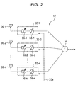
- Fig. 2 shows the structure of the variable directivity antenna 12.
- the variable directivity antenna 12 includes a plurality of antenna elements 30-1, 30-2, ⁇ , and 30-n, which are arranged in an array; weighting circuits 32-1, 32-2, ⁇ , and 32-n for regulating the amplitudes and phases of excitation currents of the antenna elements 30-1, 30-2, ⁇ , and 30-n, respectively; and an adder 34 for combining outputs from the n weighting circuits.
- the weighting circuits 32-1 to 32-n include amplitude regulators 36-1 to 36-n and phase regulators 38-1 to 38-n, respectively.
- the amplitude regulators 36-1 to 36-n and the phase regulators 38-1 to 38-n operate in accordance with an output signal 20a output from the null point setting unit 20. Regulating the amplitudes and phases by the weighting circuits 32-1 to 32-n forms a directional pattern having a directivity of a desired direction. In other words, the regulating sets a null point (nullification) in the desired direction.
- the reception unit 14 RF-amplifies spread spectrum reception signals received at the variable directivity antenna 12 and performs baseband-demodulation by removing carriers from the reception signals. Also, the reception unit 14 de-spreads the demodulated baseband signals to regenerate original transmission signals.
- the positioning unit 16 measures positions, such as distances to GPS satellites using the signals demodulated by the reception unit 14.
- the multipath determination unit 18 determines whether or not the reception signals are in a multipath state by checking the field intensities or the amounts of attenuation of the reception signals from the variable directivity antenna 12.
- the null point setting unit 20 sets a null point in a directional pattern of the variable directivity antenna 12 in accordance with an instruction from the control unit 24.
- the direction of the null point is set so as to correspond to a direction of a GPS satellite that performs positioning, that is, a direction of incoming radio waves from the GPS satellite.
- the memory 22 stores positional information on GPS satellites.
- the positional information may be, for example, almanac data representing orbital information on GPS satellites or ephemeris data including accurate orbital information on GPS satellites.
- the almanac data or the ephemeris data may be received from GPS satellites. Alternatively, the almanac data or the ephemeris data may be obtained from base stations or other data sources.
- the positional information on a GPS satellite is referred to when a null point of the variable directivity antenna 12 is set and the GPS satellite is searched for.
- the control unit 24 includes, for example, a central processing unit or a microcomputer.
- the control unit 24 in the first embodiment controls an operation of each unit of the GPS receiver and controls multipath detection performed in the GPS receiver. A process for the multipath detection is described next with reference to a flowchart shown in Fig. 3.
- the control unit 24 estimates a direction of incoming radio waves from a GPS satellite in accordance with positional information on the GPS satellite stored in the memory 22 (step S101). Then, the control unit 24 controls the null point setting unit 20 so as to form a null point in a direction corresponding to the direction of the incoming radio waves (direction of the GPS satellite) (step S102).
- the null point setting unit 20 controls the amplitudes and phases by the weighting circuits 32-1 to 32-n of the variable directivity antenna 12 using the output signal 20a, and sets a null point (step S103).
- the multipath determination unit 18 receives an output from the adder 34 of the variable directivity antenna 12 and determines whether or not the reception signal is in a multipath state (step S104).
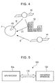
- Fig. 4 illustrates the principle of multipath detection. As shown in Fig. 4, a null point P0 in which the gain is nullified is formed in a directional pattern P of a variable directivity antenna. The null point P0 is set, for example, in a range of approximately 10 degrees, and an approximately equal gain is provided at other angles. Coefficients for regulating the amplitudes and phases are calculated in advance. Also, as described above, the direction of the null point P0 corresponds to the direction of a GPS satellite 40 that can perform positioning.
- the multipath determination unit 18 determines that the reception signal is not in a multipath state. This is because that, since radio waves from the GPS satellite 40 have a strong property of rectilinear propagation, if direct waves D are received by the variable directivity antenna 12, the intensity of the reception signal should be zero or approximately zero due to the null point P0.
- the reception signal is determined to be in the multipath state.
- a fact that the reception signal has a predetermined intensity although the intensity of the reception signal should be zero or approximately zero indicates that radio waves are received from a direction other than the direction of the null point.
- radio waves from the GPS satellite 40 are reflected by an obstacle 42, such as a high-rise building, and that indirect waves D1 are received.
- the multipath determination unit 18 When determining that the reception signal is in the multipath state in step S104, the multipath determination unit 18 outputs the determination result to the control unit 24.
- the control unit 24 excludes the GPS satellite determined to be in the multipath state from an object to be used for positioning (step S105).
- the control unit 24 searches for another GPS satellite that can perform positioning from positional information on the GPS satellites stored in the memory 22 (step S106). Then, the processing in steps S101 to S104 is repeated for the found GPS satellite, and it is determined whether or not a reception signal is in the multipath state.
- the control unit 24 gives a signal indicating permission for positioning to the positioning unit 16.
- the positioning unit 16 measures a position, such as a distance to the GPS satellite 40, in accordance with the reception signal not in the multipath state (step S107). Also, needless to say, as shown in Fig. 4, radio waves from a GPS satellite 44, which is located in a direction other than the direction of the null point P0, can be received by the variable directivity antenna 12 without being attenuated.
- the present position can be detected using a triangle intersection method or the like by positioning by a plurality of GPS satellites using a variable directivity antenna.
- a null point of a variable directivity antenna is set to a direction of a GPS satellite that can perform positioning and the intensity of a reception signal from the antenna is monitored.
- detection of whether or not the reception signal is in a multipath state can be readily performed.
- the multipath determination unit 18 compares the intensity of a reception signal with a predetermined threshold in the first embodiment, this is merely an example and other procedures can also be used. For example, the intensity of a signal received at a point other than a null point is measured in advance, and the amount of attenuation, a difference, or the like from the signal intensity is calculated. If the calculated value is more than a predetermined value, it may be determined not to be in the multipath reception state. If the calculated value is less than or equal to the predetermined value, it may be determined to be in the multipath reception state.
- a variable directivity antenna is used as a preferable antenna in the first embodiment, the present invention is not necessarily limited to this.
- An antenna that can be used in the present invention is at least required to form a null point.
- a dipole antenna for which a null point is formed in advance may be used. In this case, if the dipole antenna can rotate in a three-dimensional direction and the dipole antenna rotates at a desired angle, a null point can be set to a direction of a GPS satellite. Accordingly, the dipole antenna has a function similar to a variable directivity antenna.
- variable directivity antenna increases the number of antenna elements. In accordance with the increase in the number of antenna elements, the entire power consumption is increased. Furthermore, if a GPS receiver is installed in a movable body, such as a vehicle, wiring for antenna elements is complicated. Thus, a solar battery may be provided in an antenna portion, so that power consumption of a battery or the like for supplying power to the antenna can be reduced. Also, wireless antenna module may be arranged.
- null point may be formed so that reception signals from two GPS satellites are determined at the same time whether or not to be in a multipath state by setting the two null points to the directions of the two GPS satellites.
- two or more null points may be formed so that multipath can be detected using any one of the null points.
- a navigation system according to the second embodiment is an application of the GPS receiver according to the first embodiment to a navigation system.
- a navigation system 100 includes a GPS receiver 10a and a navigation apparatus 120 connected to the GPS receiver 10a via a connection line 110, such as a bus.
- the navigation system 100 is installed in a movable body, such as a vehicle or a vessel.
- the GPS receiver 10a further includes an input/output unit 50 for transferring signals with an external apparatus, as shown in Fig. 6.
- the input/output unit 50 functions as an interface for outputting signals for positioning by the positioning unit 16 to the connection line 110 and transferring control signals and the like between the control unit 24 and the navigation apparatus 120.
- the navigation apparatus 120 has a function to detect the present position of a vehicle in accordance with information obtained by positioning performed by the GPS receiver 10a, to provide map guidance around the present position of the vehicle, to search for the most suitable route from the present position of the vehicle to a destination, and to provide route guidance.
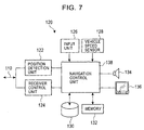
- Fig. 7 is a block diagram showing the structure of the navigation apparatus 120.
- the navigation apparatus 120 includes a position detection unit 122 for receiving an output signal from the GPS receiver 10a via the connection line 110; a receiver control unit 124 for transferring a control signal and the like with the GPS receiver 10a via the connection line 110; an input unit 126 for inputting a user instruction and the like; a vehicle speed sensor 128 for outputting vehicle speed information; a map database 130 for storing a map and the like necessary for navigation; a memory 132 for storing various data; a speaker 134 for outputting sound guidance and the like; a display 136; and a navigation control unit 138 for controlling the operations of these units.
- the position detection unit 122 receives positioning signals for a plurality of GPS satellites used for positioning by the GPS receiver 10a and detects the position of the vehicle using a triangle intersection method.
- the receiver control unit 124 sends a control signal via the connection line 110 to control the operation of the GPS receiver 10a, and transmits signals and the like from the GPS receiver 10a to the navigation control unit 138.
- the multipath determination unit 18 of the GPS receiver 10a performs multipath detection for a reception signal, and outputs the detection result to the control unit 24.
- the control unit 24 causes the input/output unit 50 to output an identification signal of the GPS satellite and a reception condition signal indicating the reception condition in accordance with the detection result. These signals are supplied to the navigation control unit 138 via the receiver control unit 124.
- the reception condition signal includes information on whether or not the GPS satellite is in the multipath state, whether or not a signal of the GPS satellite is being received, whether or not a signal of the GPS satellite cannot be received, and the like.
- the navigation control unit 138 receives information on the present position of the vehicle from the position detection unit 122, reads corresponding map data from the map database 130, and displays the map data on the display 136.
- the display 136 displays reception conditions of GPS satellites, as shown in Fig. 8.
- a mark M representing the present position of the vehicle is superimposed on a map around the present position of the vehicle.
- the reception conditions of the GPS satellites are displayed.
- GPS satellites 140 they are blacked out in Fig. 8) that are in the process of positioning
- GPS satellites 142 they are hatched in Fig. 8) that are excluded from objects to be used for positioning due to multipath
- a GPS satellite 144 whose signal cannot be received are displayed so as to be distinguishable from each other.
- the number of GPS satellites whose signals are being received is displayed in a display area 146.
- "3" is displayed in the display area 146.
- the reception conditions of the GPS satellites are displayed under the control of the navigation control unit 138 in accordance with the identification data and the reception condition signals of the GPS satellites sent from the GPS receiver 10a, as described above.
- the GPS receiver 10a is capable of always checking whether or not a reception signal from a GPS satellite is in a multipath state even if an instruction is not sent from the navigation apparatus 120.
- the GPS receiver 10a is capable of performing multipath detection at desired time in accordance with an instruction from the navigation apparatus 120.
- multipath detection may be performed when a vehicle enters the area.
- An address of an urban area including many high-rise buildings may be registered in the memory 132 as an area that is susceptible to multipath.
- the navigation control unit 138 outputs a control signal indicating to start the multipath detection from the receiver control unit 124 to the GPS receiver 10a.
- the GPS receiver 10a starts determination of whether or not a reception signal of a GPS satellite to be used for positioning is in the multipath state. In this case, until an instruction to start multipath detection is received, a null point is not set for the variable directivity antenna 12, and radio waves from all the GPS satellites can be received.
- the navigation control unit 138 may change timing of multipath detection performed by the GPS receiver 10a in accordance with a vehicle speed obtained from the vehicle speed sensor 128. Since the present position of a vehicle does not change much when the vehicle travels at a low speed, multipath detection for a GPS satellite may be performed at a longer interval. On the contrary, since the present position of the vehicle changes much more when the vehicle travels at a higher speed, multipath detection must be performed more frequently. For example, when the vehicle speed is less than a predetermined value, the GPS receiver 10a may perform multipath detection at a default time interval. When the vehicle speed is more than or equal to the predetermined value, the receiver control unit 124 may send a control signal to the GPS receiver 10a so that multipath detection is performed at a shorter time interval.
- the navigation control unit 138 may store the position of the vehicle at that time in the memory 132. Positional information on a position where multipath has occurred can be registered as a position that is susceptible to multipath, as described above.
- the GPS receiver according to the present invention can be used for navigation apparatuses installed in vehicles, vessels, or the like.
- the GPS receiver according to the present invention may be installed in portable terminal devices or the like.
- the GPS receiver according to the present invention may be used, together with a navigation function of notebook personal computers, portable telephone sets, or portable terminal devices.
Landscapes
- Engineering & Computer Science (AREA)
- Radar, Positioning & Navigation (AREA)
- Remote Sensing (AREA)
- Computer Networks & Wireless Communication (AREA)
- Physics & Mathematics (AREA)
- General Physics & Mathematics (AREA)
- Signal Processing (AREA)
- Position Fixing By Use Of Radio Waves (AREA)
- Navigation (AREA)
- Traffic Control Systems (AREA)
- Variable-Direction Aerials And Aerial Arrays (AREA)
Abstract
Description
- The present invention relates to multipath detection methods in global positioning system (GPS) receivers used for detecting the positions of movable bodies, such as vehicles.
- Receivers, such as GPS receivers, for receiving signals that are spectrum-spread by a direct spread system receive signals from a plurality of earth-orbiting GPS satellites to detect the positions of vehicles, vessels, and the like. GPS receivers using three or more GPS satellites are capable of detecting two-dimensional positions (latitude and longitude). GPS receivers using four or more GPS satellites are capable of detecting three-dimensional positions (longitude, latitude, and altitude).
- In-vehicle navigation apparatuses use such a GPS receiver so as to detect the present position of a vehicle using signals received from the GPS receiver, to display a map around the present position of the vehicle on a display, and to provide route guidance from the present position of the vehicle to a destination. Accordingly, such in-vehicle navigation apparatuses assist drivers.
- A GPS receiver in an in-vehicle navigation apparatus includes an
antenna 200 that has a directivity in the zenith direction and that is mounted on a vehicle, for example, as shown in Fig. 9. The GPS receiver receives radio waves from three or fourGPS satellites 210 via theantenna 200, performs de-spreading and demodulation on the received signals, and regenerates original transmission signals. - Also, for example, Japanese Unexamined Patent Application Publication No. 5-302972 discloses a positioning apparatus in which antennas A and B having narrow grazing angles of 1 and 2, respectively, are installed in a vehicle so that diversity reception is performed using the antennas A and B, as shown in Fig. 10. The positioning apparatus switches time-divisionally between the antennas A and B using a switching circuit, so that information from the
GPS satellites 210 received by any one of the antennas A and B is used for positioning calculation. Accordingly, time for position detection can be reduced. - However, the known in-vehicle navigation apparatuses described above have the following problems. When a vehicle provided with such a navigation apparatus travels on a road surrounded by high-rise buildings or the like in an urban area, a GPS receiver may receive multipath indirect waves due to reflection by the buildings. The GPS receiver may not detect the present position of the vehicle accurately under the influence of multipath because an error occurs in position calculation if waves other than pure direct waves from GPS satellites are used for position detection.
- In order to solve such a problem, using a beam antenna having a directivity of a particular direction reduces the influence of multipath. It is, however, practically difficult to use an antenna having a directivity of a particular direction for the GPS receiver since the GPS receiver always needs to receive radio waves from a plurality of satellites. In contrast, the GPS receiver may be provided with a multipath detection circuit so that multipath noise can be eliminated from reception signals. This arrangement, however, complicates a circuit configuration of the GPS receiver and increases the cost of the GPS receiver.
- In order to solve the above problems, an object of the present invention is to provide a receiver that has a simple structure and that is capable of detecting multipath of a reception signal with a high accuracy.
- Another object of the present invention is to provide a position detection method capable of detecting the position of a movable body with a high accuracy using the receiver; and a navigation system using the receiver.
- According to an aspect of the present invention, a receiver for receiving signals spectrum-spread by a direct spread system from satellites includes a variable directivity antenna capable of forming a null point in at least one direction; a null point setting unit for setting the null point of the variable directivity antenna in the direction of a satellite that can perform positioning; and a multipath determination unit for determining whether or not a reception signal from the variable directivity antenna is in a multipath state in accordance with the reception signal.
- The multipath determination unit may determine that the reception signal from the variable directivity antenna is in the multipath state when the reception signal has a field intensity more than or equal to a predetermined value or when the amount of attenuation of the reception signal is less than a predetermined value.
- According to another aspect of the present invention, a navigation system installed in a movable body includes a receiver provided with the characteristics described above; a position detection unit for detecting a position of the movable body in accordance with an output signal from the receiver; a map storage unit for storing data including map data; a display; and a display control unit for reading map data corresponding to the position of the movable body detected by the position detection unit from the map storage unit and displaying the map data on the display.
- According to another aspect of the present invention, a multipath detection method in a receiver for receiving signals spectrum-spread by a direct spread system from satellites includes a first step of setting a null point of a variable directivity antenna in a direction of a satellite that can perform positioning; and a second step of determining whether or not a reception signal received from the variable directivity antenna is in a multipath state in accordance with the reception signal.
- According to another aspect of the present invention, a position detection method in a navigation system for a movable body includes a first step of setting a null point of a variable directivity antenna in a direction of a global positioning system satellite that can perform positioning; a second step of determining whether or not a reception signal received from the variable directivity antenna is in a multipath state in accordance with the reception signal; and a third step of detecting a position of the movable body in accordance with a plurality of reception signals that is determined not to be in the multipath state in the second step.
- In the receiver according to the present invention, a null point of a variable directivity antenna is set to a direction of a satellite that can perform positioning and a reception signal of the antenna is monitored, so that determination of whether or not the reception signal is in a multipath state can be performed. Thus, multipath detection can be performed efficiently without reducing the intensities of reception signals from satellites that are located in directions other than the direction of the null point. Also, by using the receiver for a navigation system, the position of a movable body is detected using reception signals from satellites that are not in the multipath state. Thus, an accuracy of position detection can be further improved.
-
- Fig. 1 is a block diagram showing the structure of a GPS receiver according to a first embodiment of the present invention;
- Fig. 2 illustrates the configuration of a variable directivity antenna;
- Fig. 3 is a flowchart of a process for multipath detection in the GPS receiver;
- Fig. 4 illustrates the principle of multipath detection;
- Fig. 5 shows the structure of a navigation system according to a second embodiment of the present invention;
- Fig. 6 is a block diagram showing the structure of a GPS receiver used in the second embodiment;
- Fig. 7 is a block diagram showing the structure of a navigation apparatus;
- Fig. 8 illustrates an example of displaying reception conditions of GPS satellites;
- Fig. 9 illustrates an example of an antenna of a known GPS receiver; and
- Fig. 10 illustrates an example of antennas of a known GPS receiver.
-
- Preferred embodiments of the present invention will be described with reference to the drawings.
- Fig. 1 is a block diagram showing the structure of a GPS receiver according to a first embodiment of the present invention. A
GPS receiver 10 includes avariable directivity antenna 12; areception unit 14 for demodulating reception signals from thevariable directivity antenna 12; apositioning unit 16 for measuring positions, such as distances to GPS satellites, using signals from thereception unit 14; amultipath determination unit 18 for receiving the reception signals from thevariable directivity antenna 12 and determining whether or not the reception signals are in a multipath state; a nullpoint setting unit 20 for setting a null point at a predetermined angle of a directional pattern of thevariable directivity antenna 12; amemory 22 for storing positional information, such as almanac data, of GPS satellites; and acontrol unit 24 for controlling the operations of these units. - The
variable directivity antenna 12 is equal to a smart antenna or an adaptive antenna. Fig. 2 shows the structure of thevariable directivity antenna 12. Referring to Fig. 2, thevariable directivity antenna 12 includes a plurality of antenna elements 30-1, 30-2, ···, and 30-n, which are arranged in an array; weighting circuits 32-1, 32-2, ···, and 32-n for regulating the amplitudes and phases of excitation currents of the antenna elements 30-1, 30-2, ···, and 30-n, respectively; and anadder 34 for combining outputs from the n weighting circuits. The weighting circuits 32-1 to 32-n include amplitude regulators 36-1 to 36-n and phase regulators 38-1 to 38-n, respectively. The amplitude regulators 36-1 to 36-n and the phase regulators 38-1 to 38-n operate in accordance with anoutput signal 20a output from the nullpoint setting unit 20. Regulating the amplitudes and phases by the weighting circuits 32-1 to 32-n forms a directional pattern having a directivity of a desired direction. In other words, the regulating sets a null point (nullification) in the desired direction. - The
reception unit 14 RF-amplifies spread spectrum reception signals received at thevariable directivity antenna 12 and performs baseband-demodulation by removing carriers from the reception signals. Also, thereception unit 14 de-spreads the demodulated baseband signals to regenerate original transmission signals. - The
positioning unit 16 measures positions, such as distances to GPS satellites using the signals demodulated by thereception unit 14. Themultipath determination unit 18 determines whether or not the reception signals are in a multipath state by checking the field intensities or the amounts of attenuation of the reception signals from thevariable directivity antenna 12. - The null
point setting unit 20 sets a null point in a directional pattern of thevariable directivity antenna 12 in accordance with an instruction from thecontrol unit 24. The direction of the null point is set so as to correspond to a direction of a GPS satellite that performs positioning, that is, a direction of incoming radio waves from the GPS satellite. - The
memory 22 stores positional information on GPS satellites. The positional information may be, for example, almanac data representing orbital information on GPS satellites or ephemeris data including accurate orbital information on GPS satellites. The almanac data or the ephemeris data may be received from GPS satellites. Alternatively, the almanac data or the ephemeris data may be obtained from base stations or other data sources. The positional information on a GPS satellite is referred to when a null point of thevariable directivity antenna 12 is set and the GPS satellite is searched for. - The
control unit 24 includes, for example, a central processing unit or a microcomputer. Thecontrol unit 24 in the first embodiment controls an operation of each unit of the GPS receiver and controls multipath detection performed in the GPS receiver. A process for the multipath detection is described next with reference to a flowchart shown in Fig. 3. - The
control unit 24 estimates a direction of incoming radio waves from a GPS satellite in accordance with positional information on the GPS satellite stored in the memory 22 (step S101). Then, thecontrol unit 24 controls the nullpoint setting unit 20 so as to form a null point in a direction corresponding to the direction of the incoming radio waves (direction of the GPS satellite) (step S102). The nullpoint setting unit 20 controls the amplitudes and phases by the weighting circuits 32-1 to 32-n of thevariable directivity antenna 12 using theoutput signal 20a, and sets a null point (step S103). - The
multipath determination unit 18 receives an output from theadder 34 of thevariable directivity antenna 12 and determines whether or not the reception signal is in a multipath state (step S104). Fig. 4 illustrates the principle of multipath detection. As shown in Fig. 4, a null point P0 in which the gain is nullified is formed in a directional pattern P of a variable directivity antenna. The null point P0 is set, for example, in a range of approximately 10 degrees, and an approximately equal gain is provided at other angles. Coefficients for regulating the amplitudes and phases are calculated in advance. Also, as described above, the direction of the null point P0 corresponds to the direction of aGPS satellite 40 that can perform positioning. - When the intensity of a reception signal of the
variable directivity antenna 12 is less than a predetermined threshold, themultipath determination unit 18 determines that the reception signal is not in a multipath state. This is because that, since radio waves from theGPS satellite 40 have a strong property of rectilinear propagation, if direct waves D are received by thevariable directivity antenna 12, the intensity of the reception signal should be zero or approximately zero due to the null point P0. - In contrast, if the intensity of a reception signal is more than or equal to the predetermined threshold, the reception signal is determined to be in the multipath state. In other words, a fact that the reception signal has a predetermined intensity although the intensity of the reception signal should be zero or approximately zero indicates that radio waves are received from a direction other than the direction of the null point. In other words, it is presumed that radio waves from the
GPS satellite 40 are reflected by anobstacle 42, such as a high-rise building, and that indirect waves D1 are received. - When determining that the reception signal is in the multipath state in step S104, the
multipath determination unit 18 outputs the determination result to thecontrol unit 24. Thecontrol unit 24 excludes the GPS satellite determined to be in the multipath state from an object to be used for positioning (step S105). Thecontrol unit 24 searches for another GPS satellite that can perform positioning from positional information on the GPS satellites stored in the memory 22 (step S106). Then, the processing in steps S101 to S104 is repeated for the found GPS satellite, and it is determined whether or not a reception signal is in the multipath state. - If the
multipath determination unit 18 determines that the reception signal is not in the multipath state in step S104, thecontrol unit 24 gives a signal indicating permission for positioning to thepositioning unit 16. Thepositioning unit 16 measures a position, such as a distance to theGPS satellite 40, in accordance with the reception signal not in the multipath state (step S107). Also, needless to say, as shown in Fig. 4, radio waves from aGPS satellite 44, which is located in a direction other than the direction of the null point P0, can be received by thevariable directivity antenna 12 without being attenuated. Thus, the present position can be detected using a triangle intersection method or the like by positioning by a plurality of GPS satellites using a variable directivity antenna. - As described above, according to the first embodiment, a null point of a variable directivity antenna is set to a direction of a GPS satellite that can perform positioning and the intensity of a reception signal from the antenna is monitored. Thus, detection of whether or not the reception signal is in a multipath state can be readily performed.
- Although, the
multipath determination unit 18 compares the intensity of a reception signal with a predetermined threshold in the first embodiment, this is merely an example and other procedures can also be used. For example, the intensity of a signal received at a point other than a null point is measured in advance, and the amount of attenuation, a difference, or the like from the signal intensity is calculated. If the calculated value is more than a predetermined value, it may be determined not to be in the multipath reception state. If the calculated value is less than or equal to the predetermined value, it may be determined to be in the multipath reception state. - Although, a variable directivity antenna is used as a preferable antenna in the first embodiment, the present invention is not necessarily limited to this. An antenna that can be used in the present invention is at least required to form a null point. For example, a dipole antenna for which a null point is formed in advance may be used. In this case, if the dipole antenna can rotate in a three-dimensional direction and the dipole antenna rotates at a desired angle, a null point can be set to a direction of a GPS satellite. Accordingly, the dipole antenna has a function similar to a variable directivity antenna.
- Use of a variable directivity antenna increases the number of antenna elements. In accordance with the increase in the number of antenna elements, the entire power consumption is increased. Furthermore, if a GPS receiver is installed in a movable body, such as a vehicle, wiring for antenna elements is complicated. Thus, a solar battery may be provided in an antenna portion, so that power consumption of a battery or the like for supplying power to the antenna can be reduced. Also, wireless antenna module may be arranged.
- In addition, although a null point is formed in the first embodiment, two null points may be formed so that reception signals from two GPS satellites are determined at the same time whether or not to be in a multipath state by setting the two null points to the directions of the two GPS satellites. In addition, two or more null points may be formed so that multipath can be detected using any one of the null points.
- A second embodiment of the present invention is described next. A navigation system according to the second embodiment is an application of the GPS receiver according to the first embodiment to a navigation system. As shown in Fig. 5, a
navigation system 100 includes aGPS receiver 10a and anavigation apparatus 120 connected to theGPS receiver 10a via aconnection line 110, such as a bus. Preferably, thenavigation system 100 is installed in a movable body, such as a vehicle or a vessel. - In addition to the structure shown in Fig. 1, the
GPS receiver 10a further includes an input/output unit 50 for transferring signals with an external apparatus, as shown in Fig. 6. The input/output unit 50 functions as an interface for outputting signals for positioning by thepositioning unit 16 to theconnection line 110 and transferring control signals and the like between thecontrol unit 24 and thenavigation apparatus 120. - In contrast, as is well known, the
navigation apparatus 120 has a function to detect the present position of a vehicle in accordance with information obtained by positioning performed by theGPS receiver 10a, to provide map guidance around the present position of the vehicle, to search for the most suitable route from the present position of the vehicle to a destination, and to provide route guidance. - Fig. 7 is a block diagram showing the structure of the
navigation apparatus 120. Thenavigation apparatus 120 includes aposition detection unit 122 for receiving an output signal from theGPS receiver 10a via theconnection line 110; areceiver control unit 124 for transferring a control signal and the like with theGPS receiver 10a via theconnection line 110; aninput unit 126 for inputting a user instruction and the like; avehicle speed sensor 128 for outputting vehicle speed information; amap database 130 for storing a map and the like necessary for navigation; amemory 132 for storing various data; aspeaker 134 for outputting sound guidance and the like; adisplay 136; and anavigation control unit 138 for controlling the operations of these units. - The
position detection unit 122 receives positioning signals for a plurality of GPS satellites used for positioning by theGPS receiver 10a and detects the position of the vehicle using a triangle intersection method. Thereceiver control unit 124 sends a control signal via theconnection line 110 to control the operation of theGPS receiver 10a, and transmits signals and the like from theGPS receiver 10a to thenavigation control unit 138. - The operation for position detection in the
navigation system 100 according to the second embodiment will now be explained. Themultipath determination unit 18 of theGPS receiver 10a performs multipath detection for a reception signal, and outputs the detection result to thecontrol unit 24. Thecontrol unit 24 causes the input/output unit 50 to output an identification signal of the GPS satellite and a reception condition signal indicating the reception condition in accordance with the detection result. These signals are supplied to thenavigation control unit 138 via thereceiver control unit 124. The reception condition signal includes information on whether or not the GPS satellite is in the multipath state, whether or not a signal of the GPS satellite is being received, whether or not a signal of the GPS satellite cannot be received, and the like. - If the reception signal is not in the multipath state, a signal from the
positioning unit 16 is sent to theposition detection unit 122, so that theposition detection unit 122 detects the position of the vehicle. Since a multipath signal is not used for the position detection, the position of the vehicle can be detected accurately. Thenavigation control unit 138 receives information on the present position of the vehicle from theposition detection unit 122, reads corresponding map data from themap database 130, and displays the map data on thedisplay 136. - Furthermore, the
display 136 displays reception conditions of GPS satellites, as shown in Fig. 8. In other words, on the left screen, a mark M representing the present position of the vehicle is superimposed on a map around the present position of the vehicle. On the right screen, the reception conditions of the GPS satellites are displayed. GPS satellites 140 (they are blacked out in Fig. 8) that are in the process of positioning, GPS satellites 142 (they are hatched in Fig. 8) that are excluded from objects to be used for positioning due to multipath, and aGPS satellite 144 whose signal cannot be received are displayed so as to be distinguishable from each other. In the top right corner, the number of GPS satellites whose signals are being received is displayed in adisplay area 146. In Fig. 8, "3" is displayed in thedisplay area 146. The reception conditions of the GPS satellites are displayed under the control of thenavigation control unit 138 in accordance with the identification data and the reception condition signals of the GPS satellites sent from theGPS receiver 10a, as described above. - An example in which the
navigation apparatus 120 controls theGPS receiver 10a is described next. TheGPS receiver 10a is capable of always checking whether or not a reception signal from a GPS satellite is in a multipath state even if an instruction is not sent from thenavigation apparatus 120. However, theGPS receiver 10a is capable of performing multipath detection at desired time in accordance with an instruction from thenavigation apparatus 120. - For example, by defining an area that is susceptible to multipath in advance, multipath detection may be performed when a vehicle enters the area. An address of an urban area including many high-rise buildings may be registered in the
memory 132 as an area that is susceptible to multipath. When determining that the vehicle enters the area stored in thememory 132 in accordance with information on the present position of the vehicle from theposition detection unit 122, thenavigation control unit 138 outputs a control signal indicating to start the multipath detection from thereceiver control unit 124 to theGPS receiver 10a. In response to the control signal, theGPS receiver 10a starts determination of whether or not a reception signal of a GPS satellite to be used for positioning is in the multipath state. In this case, until an instruction to start multipath detection is received, a null point is not set for thevariable directivity antenna 12, and radio waves from all the GPS satellites can be received. - Also, the
navigation control unit 138 may change timing of multipath detection performed by theGPS receiver 10a in accordance with a vehicle speed obtained from thevehicle speed sensor 128. Since the present position of a vehicle does not change much when the vehicle travels at a low speed, multipath detection for a GPS satellite may be performed at a longer interval. On the contrary, since the present position of the vehicle changes much more when the vehicle travels at a higher speed, multipath detection must be performed more frequently. For example, when the vehicle speed is less than a predetermined value, theGPS receiver 10a may perform multipath detection at a default time interval. When the vehicle speed is more than or equal to the predetermined value, thereceiver control unit 124 may send a control signal to theGPS receiver 10a so that multipath detection is performed at a shorter time interval. - Also, when the
GPS receiver 10a detects multipath, thenavigation control unit 138 may store the position of the vehicle at that time in thememory 132. Positional information on a position where multipath has occurred can be registered as a position that is susceptible to multipath, as described above. - Although the preferred embodiments of the present invention have been described, the present invention is not limited to a particular embodiment. Various modifications and changes may be made to the present invention without departing from the sprit and scope of the present invention as defined by the claims.
- Obviously, the GPS receiver according to the present invention can be used for navigation apparatuses installed in vehicles, vessels, or the like. In addition, the GPS receiver according to the present invention may be installed in portable terminal devices or the like. For example, the GPS receiver according to the present invention may be used, together with a navigation function of notebook personal computers, portable telephone sets, or portable terminal devices.
Claims (10)
- A receiver (10) for receiving signals spectrum-spread by a direct spread system from satellites, characterized by comprising:a variable directivity antenna (12) capable of forming a null point in at least one direction;null point setting means (20) for setting the null point of the variable directivity antenna (12) in the direction of a satellite that can perform positioning; andmultipath determination means (18) for determining whether or not a reception signal from the variable directivity antenna (12) is in a multipath state in accordance with the reception signal.
- The receiver (10) according to Claim 1, characterized in that the multipath determination means (18) determines that the reception signal from the variable directivity antenna (12) is in the multipath state when the reception signal has a field intensity equal to or more than a predetermined value or when the amount of attenuation of the reception signal is less than a predetermined value.
- The receiver (10) according to Claim 1 or 2, characterized by further comprising storage means (22) for storing positional information on the satellites, wherein
the null point setting means (20) sets the null point in accordance with positional information on the satellite stored in the storage means (22). - The receiver (10) according to Claim 3, characterized by further comprising control means in which, when the multipath determination means (18) determines that the reception signal is in the multipath state, the control means excludes the satellite from an object to be used for positioning, searches for another satellite that can perform positioning in accordance with positional information on the other satellite stored in the storage means (22), and controls the null point setting means (20) so as to set a null point in a direction of the other satellite.
- The receiver (10a) according to any preceding claim, characterized by being connected to a navigation apparatus (120) including: position detection means (122) for detecting a position of a movable body; map storage means (130) for storing data including map data; a display (136); and display control means (138) for reading map data corresponding to the position of the movable body detected by the position detection means (122) from the map storage means (130) and displaying the map data on the display (136).
- A multipath detection method in a receiver (10) for receiving signals spectrum-spread by a direct spread system from satellites, characterized by comprising:a first step of setting a null point of a variable directivity antenna (12) in a direction of a satellite that can perform positioning; anda second step of determining whether or not a reception signal received from the variable directivity antenna (12) is in a multipath state in accordance with the reception signal.
- The multipath detection method according to Claim 6 or 7, characterized in that, in the second step, when the intensity of the reception signal is more than or equal to a predetermined value, the reception signal is determined to be in the multipath state.
- The multipath detection method according to Claim 6, characterized in that, in the first step, a direction of incoming radio waves from the satellite is estimated in accordance with positional information on the satellite stored in advance in a memory, and the null point is set in the estimated direction.
- The multipath detection method according to Claim 6 or 7, characterized in that, in the first step, a direction of incoming radio waves from the satellite is estimated in accordance with almanac data, and the null point is set in the estimated direction.
- The multipath detection method according to any of Claims 6 to 9, characterized by further comprising:a third step of excluding the satellite from an object to be used for positioning when the reception signal is determined to be in the multipath state in the second step; anda fourth step of performing the first step and the second step for another satellite that can perform positioning.
Applications Claiming Priority (2)
| Application Number | Priority Date | Filing Date | Title |
|---|---|---|---|
| JP2004001861 | 2004-01-07 | ||
| JP2004001861A JP4222950B2 (en) | 2004-01-07 | 2004-01-07 | Multipath detection method in GPS receiver and navigation system using the same |
Publications (2)
| Publication Number | Publication Date |
|---|---|
| EP1553424A1 true EP1553424A1 (en) | 2005-07-13 |
| EP1553424B1 EP1553424B1 (en) | 2006-06-21 |
Family
ID=34587680
Family Applications (1)
| Application Number | Title | Priority Date | Filing Date |
|---|---|---|---|
| EP04257636A Expired - Lifetime EP1553424B1 (en) | 2004-01-07 | 2004-12-08 | Receiver, navigation system using receiver and multipath detection method and position detection method in receiver |
Country Status (5)
| Country | Link |
|---|---|
| US (1) | US7116270B2 (en) |
| EP (1) | EP1553424B1 (en) |
| JP (1) | JP4222950B2 (en) |
| CN (1) | CN100507595C (en) |
| DE (1) | DE602004001326T2 (en) |
Cited By (3)
| Publication number | Priority date | Publication date | Assignee | Title |
|---|---|---|---|---|
| EP2177929A1 (en) * | 2008-10-17 | 2010-04-21 | European Space Agency | Navigation-satellite tracking method and receiving station |
| GB2494150A (en) * | 2011-08-31 | 2013-03-06 | Samsung Electronics Co Ltd | Multipath mitigation in positioning systems |
| EP3995860A1 (en) * | 2020-11-05 | 2022-05-11 | u-blox AG | Method of and receiver for mitigating multipath interference in a global navigation satellite system |
Families Citing this family (13)
| Publication number | Priority date | Publication date | Assignee | Title |
|---|---|---|---|---|
| JP2007078647A (en) * | 2005-09-16 | 2007-03-29 | Seiko Epson Corp | GPS receiver |
| DE102007036248A1 (en) | 2007-08-02 | 2009-02-05 | Robert Bosch Gmbh | signaling device |
| JP5125493B2 (en) * | 2007-12-26 | 2013-01-23 | セイコーエプソン株式会社 | Multipath signal determination method, program, and multipath signal determination apparatus |
| US8933840B2 (en) | 2009-06-08 | 2015-01-13 | Nec Corporation | Control method of wireless communication system, wireless communication system, wireless communication apparatus, and adjustment method of array weight vector |
| CN101655546B (en) * | 2009-09-22 | 2012-02-01 | 西北工业大学 | Method for estimating satellite navigation direct signal parameter and multipath signal number and parameter |
| US8669900B2 (en) * | 2010-11-17 | 2014-03-11 | Trimble Navigation Limited | Global navigation satellite antenna systems and methods |
| KR101334103B1 (en) | 2012-01-13 | 2013-11-28 | 주식회사 삼정솔루션 | Gps jamming detector |
| JP6064347B2 (en) * | 2012-03-22 | 2017-01-25 | カシオ計算機株式会社 | Information processing apparatus and program |
| KR101948813B1 (en) * | 2017-08-17 | 2019-02-18 | 국방과학연구소 | Apparatus and method for estimating angle-of-arrival of gps signal |
| JP2019039696A (en) * | 2017-08-22 | 2019-03-14 | 株式会社エンルート | Unmanned air vehicle and positioning method by unmanned air vehicle |
| CN110071733B (en) * | 2019-04-29 | 2021-05-28 | 深圳成谷科技有限公司 | System and method for expanding receiving range of vehicle-mounted unit |
| WO2021006866A1 (en) * | 2019-07-08 | 2021-01-14 | Google Llc | Enhancing sensitivity to reflected gnss signals |
| WO2021166222A1 (en) * | 2020-02-21 | 2021-08-26 | 日本電気株式会社 | Positioning device and positioning method |
Citations (4)
| Publication number | Priority date | Publication date | Assignee | Title |
|---|---|---|---|---|
| US4959653A (en) * | 1989-08-23 | 1990-09-25 | Massachusetts Institute Of Technology | Adaptive sidelobe blanker |
| US6084540A (en) * | 1998-07-20 | 2000-07-04 | Lockheed Martin Corp. | Determination of jammer directions using multiple antenna beam patterns |
| US6166690A (en) * | 1999-07-02 | 2000-12-26 | Sensor Systems, Inc. | Adaptive nulling methods for GPS reception in multiple-interference environments |
| US6618016B1 (en) * | 2001-02-21 | 2003-09-09 | Bae Systems Aerospace Inc. | Eight-element anti-jam aircraft GPS antennas |
Family Cites Families (12)
| Publication number | Priority date | Publication date | Assignee | Title |
|---|---|---|---|---|
| JPS62883A (en) * | 1985-06-27 | 1987-01-06 | Toshiba Corp | Navigation system |
| JPS6431075A (en) * | 1987-07-28 | 1989-02-01 | Furuno Electric Co | Antenna-switching control apparatus |
| JPH0915318A (en) * | 1996-07-31 | 1997-01-17 | Sony Corp | Global Positioning System Receiver |
| US5940026A (en) * | 1997-07-21 | 1999-08-17 | Rockwell Science Center, Inc. | Azimuth determination for GPS/INS systems via GPS null steering antenna |
| JP2001215268A (en) * | 2000-01-31 | 2001-08-10 | Sony Corp | Global positioning system receiver |
| JP3722461B2 (en) * | 2000-03-24 | 2005-11-30 | パイオニア株式会社 | Current position detection device using GPS |
| JP2001311767A (en) * | 2000-04-28 | 2001-11-09 | Clarion Co Ltd | Gps receiver and multi-path judging method in gps receiver |
| JP2002026631A (en) * | 2000-07-11 | 2002-01-25 | Jatco Transtechnology Ltd | GPS antenna device |
| JP3593960B2 (en) * | 2000-08-21 | 2004-11-24 | 日本電気株式会社 | Multi-beam antenna equipment |
| US6727846B1 (en) * | 2000-09-20 | 2004-04-27 | Navsys Corporation | Apparatus and method for minimizing multipath signal errors during tracking of GPS satellite signals |
| US6992624B2 (en) * | 2004-06-22 | 2006-01-31 | Novatel Inc. | Attitude determination system using null-steered array |
| US20060033659A1 (en) * | 2004-08-10 | 2006-02-16 | Ems Technologies Canada, Ltd. | Mobile satcom antenna discrimination enhancement |
-
2004
- 2004-01-07 JP JP2004001861A patent/JP4222950B2/en not_active Expired - Fee Related
- 2004-12-08 EP EP04257636A patent/EP1553424B1/en not_active Expired - Lifetime
- 2004-12-08 DE DE602004001326T patent/DE602004001326T2/en not_active Expired - Fee Related
-
2005
- 2005-01-05 US US11/029,268 patent/US7116270B2/en not_active Expired - Lifetime
- 2005-01-07 CN CNB2005100038438A patent/CN100507595C/en not_active Expired - Fee Related
Patent Citations (4)
| Publication number | Priority date | Publication date | Assignee | Title |
|---|---|---|---|---|
| US4959653A (en) * | 1989-08-23 | 1990-09-25 | Massachusetts Institute Of Technology | Adaptive sidelobe blanker |
| US6084540A (en) * | 1998-07-20 | 2000-07-04 | Lockheed Martin Corp. | Determination of jammer directions using multiple antenna beam patterns |
| US6166690A (en) * | 1999-07-02 | 2000-12-26 | Sensor Systems, Inc. | Adaptive nulling methods for GPS reception in multiple-interference environments |
| US6618016B1 (en) * | 2001-02-21 | 2003-09-09 | Bae Systems Aerospace Inc. | Eight-element anti-jam aircraft GPS antennas |
Cited By (7)
| Publication number | Priority date | Publication date | Assignee | Title |
|---|---|---|---|---|
| EP2177929A1 (en) * | 2008-10-17 | 2010-04-21 | European Space Agency | Navigation-satellite tracking method and receiving station |
| US8134498B2 (en) | 2008-10-17 | 2012-03-13 | European Space Agency | Navigation-satellite tracking method and receiving station |
| GB2494150A (en) * | 2011-08-31 | 2013-03-06 | Samsung Electronics Co Ltd | Multipath mitigation in positioning systems |
| GB2494150B (en) * | 2011-08-31 | 2015-11-04 | Samsung Electronics Co Ltd | Multipath mitigation in positioning systems |
| US10267922B2 (en) | 2011-08-31 | 2019-04-23 | Samsung Electronics Co., Ltd. | Multipath mitigation in positioning systems |
| EP3995860A1 (en) * | 2020-11-05 | 2022-05-11 | u-blox AG | Method of and receiver for mitigating multipath interference in a global navigation satellite system |
| US11585944B2 (en) | 2020-11-05 | 2023-02-21 | U-Blox Ag | Method of and receiver for mitigating multipath interference in a global navigation satellite system |
Also Published As
| Publication number | Publication date |
|---|---|
| US7116270B2 (en) | 2006-10-03 |
| US20050195108A1 (en) | 2005-09-08 |
| DE602004001326D1 (en) | 2006-08-03 |
| EP1553424B1 (en) | 2006-06-21 |
| JP4222950B2 (en) | 2009-02-12 |
| CN100507595C (en) | 2009-07-01 |
| JP2005195448A (en) | 2005-07-21 |
| DE602004001326T2 (en) | 2007-05-24 |
| CN1637431A (en) | 2005-07-13 |
Similar Documents
| Publication | Publication Date | Title |
|---|---|---|
| US7116270B2 (en) | Method and system for multipath detection | |
| CN114026388B (en) | Position estimation device and position estimation method | |
| US6587689B1 (en) | Multi-sensor assisted cellular handoff technique | |
| US6542119B2 (en) | GPS antenna array | |
| GB2445384A (en) | Determining the position of a signal source | |
| JP2001264076A (en) | Car navigation system | |
| US20060227044A1 (en) | Positioning device, control method of positioning device, control program for positioning device, and computer-readable recording medium having positioning device controlling program recorded therein | |
| JP6511890B2 (en) | Direction estimation system and direction estimation apparatus | |
| US6721656B2 (en) | GPS receiving apparatus | |
| JP4357357B2 (en) | GPS satellite positioning device, positioning method, and navigation device using the same | |
| JPH0778532B2 (en) | Diversity reception GPS receiver | |
| JPH0791976A (en) | Position measuring method by satellite navigation | |
| JP2012225769A (en) | Positioning system | |
| JPH02268528A (en) | Receiver for vehicle | |
| JP2813219B2 (en) | Tracking device for moving objects | |
| JP7372436B2 (en) | Positioning device, positioning method and program | |
| JP4594367B2 (en) | Mobile station, communication control method | |
| JP4779852B2 (en) | Portable navigation device and navigation program | |
| KR101838012B1 (en) | method for searching spurious source based of GPS information | |
| JPH04120486A (en) | On-vehicle position detector | |
| JPS61284687A (en) | Gps navigation device | |
| JP4166606B2 (en) | Mobile station, communication control method | |
| JP2021162355A (en) | Antenna control system, control device and control program | |
| JP2004163195A (en) | Position information output device | |
| JP2021117035A (en) | Radio wave arrival direction estimation device |
Legal Events
| Date | Code | Title | Description |
|---|---|---|---|
| PUAI | Public reference made under article 153(3) epc to a published international application that has entered the european phase |
Free format text: ORIGINAL CODE: 0009012 |
|
| AK | Designated contracting states |
Kind code of ref document: A1 Designated state(s): AT BE BG CH CY CZ DE DK EE ES FI FR GB GR HU IE IS IT LI LT LU MC NL PL PT RO SE SI SK TR |
|
| AX | Request for extension of the european patent |
Extension state: AL BA HR LV MK YU |
|
| 17P | Request for examination filed |
Effective date: 20050523 |
|
| GRAP | Despatch of communication of intention to grant a patent |
Free format text: ORIGINAL CODE: EPIDOSNIGR1 |
|
| GRAS | Grant fee paid |
Free format text: ORIGINAL CODE: EPIDOSNIGR3 |
|
| AKX | Designation fees paid |
Designated state(s): DE FR GB |
|
| GRAA | (expected) grant |
Free format text: ORIGINAL CODE: 0009210 |
|
| AK | Designated contracting states |
Kind code of ref document: B1 Designated state(s): DE FR GB |
|
| REG | Reference to a national code |
Ref country code: GB Ref legal event code: FG4D |
|
| REF | Corresponds to: |
Ref document number: 602004001326 Country of ref document: DE Date of ref document: 20060803 Kind code of ref document: P |
|
| ET | Fr: translation filed | ||
| PLBE | No opposition filed within time limit |
Free format text: ORIGINAL CODE: 0009261 |
|
| STAA | Information on the status of an ep patent application or granted ep patent |
Free format text: STATUS: NO OPPOSITION FILED WITHIN TIME LIMIT |
|
| 26N | No opposition filed |
Effective date: 20070322 |
|
| PGFP | Annual fee paid to national office [announced via postgrant information from national office to epo] |
Ref country code: FR Payment date: 20081110 Year of fee payment: 5 |
|
| PGFP | Annual fee paid to national office [announced via postgrant information from national office to epo] |
Ref country code: DE Payment date: 20081128 Year of fee payment: 5 |
|
| PGFP | Annual fee paid to national office [announced via postgrant information from national office to epo] |
Ref country code: GB Payment date: 20081120 Year of fee payment: 5 |
|
| GBPC | Gb: european patent ceased through non-payment of renewal fee |
Effective date: 20091208 |
|
| REG | Reference to a national code |
Ref country code: FR Ref legal event code: ST Effective date: 20100831 |
|
| PG25 | Lapsed in a contracting state [announced via postgrant information from national office to epo] |
Ref country code: FR Free format text: LAPSE BECAUSE OF NON-PAYMENT OF DUE FEES Effective date: 20091231 |
|
| PG25 | Lapsed in a contracting state [announced via postgrant information from national office to epo] |
Ref country code: DE Free format text: LAPSE BECAUSE OF NON-PAYMENT OF DUE FEES Effective date: 20100701 |
|
| PG25 | Lapsed in a contracting state [announced via postgrant information from national office to epo] |
Ref country code: GB Free format text: LAPSE BECAUSE OF NON-PAYMENT OF DUE FEES Effective date: 20091208 |