EP1553382A1 - Tape measure with laser - Google Patents
Tape measure with laser Download PDFInfo
- Publication number
- EP1553382A1 EP1553382A1 EP05000125A EP05000125A EP1553382A1 EP 1553382 A1 EP1553382 A1 EP 1553382A1 EP 05000125 A EP05000125 A EP 05000125A EP 05000125 A EP05000125 A EP 05000125A EP 1553382 A1 EP1553382 A1 EP 1553382A1
- Authority
- EP
- European Patent Office
- Prior art keywords
- housing
- tape measure
- light plane
- neck
- plane generator
- Prior art date
- Legal status (The legal status is an assumption and is not a legal conclusion. Google has not performed a legal analysis and makes no representation as to the accuracy of the status listed.)
- Granted
Links
Images

Classifications
-
- G—PHYSICS
- G01—MEASURING; TESTING
- G01C—MEASURING DISTANCES, LEVELS OR BEARINGS; SURVEYING; NAVIGATION; GYROSCOPIC INSTRUMENTS; PHOTOGRAMMETRY OR VIDEOGRAMMETRY
- G01C15/00—Surveying instruments or accessories not provided for in groups G01C1/00 - G01C13/00
- G01C15/002—Active optical surveying means
- G01C15/004—Reference lines, planes or sectors
-
- G—PHYSICS
- G01—MEASURING; TESTING
- G01B—MEASURING LENGTH, THICKNESS OR SIMILAR LINEAR DIMENSIONS; MEASURING ANGLES; MEASURING AREAS; MEASURING IRREGULARITIES OF SURFACES OR CONTOURS
- G01B3/00—Measuring instruments characterised by the use of mechanical techniques
- G01B3/10—Measuring tapes
- G01B3/1041—Measuring tapes characterised by casings
- G01B3/1046—Details of external structure thereof, e.g. shapes for ensuring firmer hold
- G01B3/1048—Integrated means for affixing or holding
-
- G—PHYSICS
- G01—MEASURING; TESTING
- G01B—MEASURING LENGTH, THICKNESS OR SIMILAR LINEAR DIMENSIONS; MEASURING ANGLES; MEASURING AREAS; MEASURING IRREGULARITIES OF SURFACES OR CONTOURS
- G01B3/00—Measuring instruments characterised by the use of mechanical techniques
- G01B3/10—Measuring tapes
- G01B3/1084—Tapes combined with arrangements for functions other than measuring lengths
- G01B2003/1087—Tapes combined with arrangements for functions other than measuring lengths for illuminating
-
- Y—GENERAL TAGGING OF NEW TECHNOLOGICAL DEVELOPMENTS; GENERAL TAGGING OF CROSS-SECTIONAL TECHNOLOGIES SPANNING OVER SEVERAL SECTIONS OF THE IPC; TECHNICAL SUBJECTS COVERED BY FORMER USPC CROSS-REFERENCE ART COLLECTIONS [XRACs] AND DIGESTS
- Y10—TECHNICAL SUBJECTS COVERED BY FORMER USPC
- Y10S—TECHNICAL SUBJECTS COVERED BY FORMER USPC CROSS-REFERENCE ART COLLECTIONS [XRACs] AND DIGESTS
- Y10S33/00—Geometrical instruments
- Y10S33/21—Geometrical instruments with laser
Definitions
- This invention relates generally to tape measures and more specifically to a tape measure in combination with a laser device.
- Tape measures are well known devices used to measure distances, and are helpful in marking distances. It is desired to provide a device that enables the user to measure and/or mark distances more accurately.
- an improved tape measure is employed.
- the tape measure has a housing, a rule blade coilable within the housing, and a light plane generator disposed on the housing, the light plane generator including a laser source for emitting a laser beam and a line lens in the path of the laser beam for converting the laser beam into a laser plane.
- the laser plane intersects both the rule blade and a workpiece.
- the light plane generator may be pivoted about a horizontal axis and/or a vertical axis.
- a tape measure 10 may have a housing 11, an elongated flexible rule blade 12 (also known as a tape) which is carried on a controllable spring-biased reel assembly (not shown) disposed within housing 11, and a blade locking mechanism (not shown) actuated by a blade locking actuator (not shown) for locking the elongated blade 12 into a desired position to prevent the blade 12 from being further extended from the housing and from being wound into the housing by the spring-bias of the reel assembly.
- a blade locking mechanism not shown
- actuated by a blade locking actuator not shown
- the tape measure 10 may also have a light plane generator 20.
- the light plane generator 20 preferably generates a plane of light LP so that, when tape measure 10 is placed on a workpiece W, the light plane LP contacts the workpiece W and/or the blade 12, creating a light line LL thereon.
- the light plane generator 20 has a housing 22, a laser diode 23 disposed in the housing for generating a laser beam, a collimating lens 24 for collimating the laser beam, and a line lens 25 for converting the laser beam into a laser light plane LP.
- Line lens 25 may be a cylindrical lens.
- This assembly is preferably pivotally connected to an L-shaped neck 21, which may be pivotally attached to housing 11. Accordingly, a user can adjust the light plane generator about a horizontal axis HA and/or a vertical axis VA.
- Light plane generator 20 may also include a battery 30 for powering the laser diode 23.
- Battery 30 may be disposed in housing 11 or housing 22.
- Light plane generator 20 may also include a switch 31 for turning laser diode 23 on and off. Switch 31 may be housing 11 or housing 22.
- neck 21 may have detent notches 27 that receive a ball 26, which is biased towards neck 21 by a spring 28.
- detent notches 27 and ball 26 may also be provided on housing 11 and neck 21, respectively.
- Bracket 40 may include a U-shaped body 41 for receiving tape measure 10 and a flange 42 extending downwardly. With such arrangement, the user can place flange 42 against an edge of workpiece W, thus mounting tape measure 10 at the periphery of the workpiece W.
- bracket 40 can be disposed on tape measure 10 in two positions: with the flange 42 on the left side (shown in solid lines in FIG. 3); and with the flange 42 on the right side (shown in broken lines in FIG. 3).
- the user can place the tape measure 10 on bracket 40, place both on workpiece W, pull blade 12 and hook the edge of workpiece W with tab 13.
- the user can then turn on the light plane generator 20 by moving switch 31.
- Light plane generator 20 then generates a light plane LP which creates a light line LL on workpiece W.
- the user can rotate housing 22 about the horizontal axis HA so that the light plane LP also lights blade 12. Accordingly, light line LL will show on both blade 12 and workpiece W.
- the user can rotate light plane generator 20 about vertical axis VA to change the angle of light line LL relative to blade 12, as shown in broken lines in FIG. 4.
- the light line LL extends rightwardly from blade 12.
- the user need only rotate housing 22 about the horizontal axis HA in order for light line LL to extend leftwardly from blade 12.
- Bracket 50 may be disposed on tape measure 10. Bracket 50 may include a flange 51 which is pivotably attached to housing 11 via shaft 52. This would allow the user to rotate the flange 51 between a first position where the flange 51 does not contact workpiece W (shown in FIG. 5A) and a second position where the flange 51 contacts an edge of workpiece W (shown in FIG. 5B).
- bracket 50 may be separable from housing 11 and inserted on the other side thereof. This would allow the user to move the bracket 50 to contact a different edge of workpiece W, etc.
- housing 11 may carry two brackets 50 non-removably and rotatably attached to housing 11.
Abstract
Description
- This invention relates generally to tape measures and more specifically to a tape measure in combination with a laser device.
- Tape measures are well known devices used to measure distances, and are helpful in marking distances. It is desired to provide a device that enables the user to measure and/or mark distances more accurately.
- It is an object of the present invention to provide a laser level that is inexpensive and usable by the general public.
- In accordance with the present invention, an improved tape measure is employed. The tape measure has a housing, a rule blade coilable within the housing, and a light plane generator disposed on the housing, the light plane generator including a laser source for emitting a laser beam and a line lens in the path of the laser beam for converting the laser beam into a laser plane. Preferably, the laser plane intersects both the rule blade and a workpiece. The light plane generator may be pivoted about a horizontal axis and/or a vertical axis.
- Additional features and benefits of the present invention are described, and will be apparent from, the accompanying drawings and the detailed description below.
- The accompanying drawings illustrate preferred embodiments of the invention according to the practical application of the principles thereof, and in which:
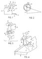
- FIG. 1 is a side view of a tape measure according to the invention;
- FIG. 2 is a cross-sectional view along line A-A of FIG. 1;
- FIG. 3 shows the tape measure used with a bracket;
- FIG. 4 shows the tape measure on a workpiece;
- FIG. 5 shows the tape measure with an alternative bracket, where FIGS. 5A-5B illustrate the bracket in a first and second position, respectively, and FIG. 5C shows different installation alternatives for such brackets.
-
- The invention is now described with reference to the accompanying figures, wherein like numerals designate like parts. Referring to FIG. 1, a
tape measure 10 may have ahousing 11, an elongated flexible rule blade 12 (also known as a tape) which is carried on a controllable spring-biased reel assembly (not shown) disposed withinhousing 11, and a blade locking mechanism (not shown) actuated by a blade locking actuator (not shown) for locking theelongated blade 12 into a desired position to prevent theblade 12 from being further extended from the housing and from being wound into the housing by the spring-bias of the reel assembly. Persons skilled in the art will recognize that details of any of the parts referred to above, as well as further information on such tape measure, can be found in US Patent No. 6,209,219, which is hereby wholly incorporated herein by reference. - The
tape measure 10 may also have alight plane generator 20. Referring to FIGS. 1-4, thelight plane generator 20 preferably generates a plane of light LP so that, whentape measure 10 is placed on a workpiece W, the light plane LP contacts the workpiece W and/or theblade 12, creating a light line LL thereon. Preferably, thelight plane generator 20 has ahousing 22, alaser diode 23 disposed in the housing for generating a laser beam, a collimatinglens 24 for collimating the laser beam, and aline lens 25 for converting the laser beam into a laser light plane LP.Line lens 25 may be a cylindrical lens. - This assembly is preferably pivotally connected to an L-
shaped neck 21, which may be pivotally attached tohousing 11. Accordingly, a user can adjust the light plane generator about a horizontal axis HA and/or a vertical axis VA. -
Light plane generator 20 may also include abattery 30 for powering thelaser diode 23.Battery 30 may be disposed inhousing 11 orhousing 22.Light plane generator 20 may also include aswitch 31 for turninglaser diode 23 on and off. Switch 31 may behousing 11 orhousing 22. - It is preferable to provide a detent system for enabling the user to quickly locate the most common positions of the neck 21 (and thus light plane generator 20) relative to
housing 11. Accordingly,neck 21 may have detentnotches 27 that receive aball 26, which is biased towardsneck 21 by aspring 28. Persons skilled in the art will recognize thatdetent notches 27 andball 26 may also be provided onhousing 11 andneck 21, respectively. - It may be preferable to place
tape measure 10 on abracket 40.Bracket 40 may include aU-shaped body 41 for receivingtape measure 10 and aflange 42 extending downwardly. With such arrangement, the user can placeflange 42 against an edge of workpiece W, thus mountingtape measure 10 at the periphery of the workpiece W. Persons skilled in the art will recognize thatbracket 40 can be disposed ontape measure 10 in two positions: with theflange 42 on the left side (shown in solid lines in FIG. 3); and with theflange 42 on the right side (shown in broken lines in FIG. 3). - With such arrangement, the user can place the tape measure 10 on
bracket 40, place both on workpiece W, pullblade 12 and hook the edge of workpiece W withtab 13. The user can then turn on thelight plane generator 20 by movingswitch 31.Light plane generator 20 then generates a light plane LP which creates a light line LL on workpiece W. The user can rotatehousing 22 about the horizontal axis HA so that the light plane LP also lightsblade 12. Accordingly, light line LL will show on bothblade 12 and workpiece W. If desired, the user can rotatelight plane generator 20 about vertical axis VA to change the angle of light line LL relative toblade 12, as shown in broken lines in FIG. 4. - Persons skilled in the art will recognize that, in the embodiment shown in FIG. 4, the light line LL extends rightwardly from
blade 12. However, the user need only rotatehousing 22 about the horizontal axis HA in order for light line LL to extend leftwardly fromblade 12. - Persons skilled in the art will recognize that other brackets may be used with
tape measure 10. Referring to FIG. 5,tape measure 10. Referring to FIG. 5, abracket 50 may be disposed ontape measure 10.Bracket 50 may include aflange 51 which is pivotably attached tohousing 11 viashaft 52. This would allow the user to rotate theflange 51 between a first position where theflange 51 does not contact workpiece W (shown in FIG. 5A) and a second position where theflange 51 contacts an edge of workpiece W (shown in FIG. 5B). - As shown in FIG. 5C,
bracket 50 may be separable fromhousing 11 and inserted on the other side thereof. This would allow the user to move thebracket 50 to contact a different edge of workpiece W, etc. Alternatively,housing 11 may carry twobrackets 50 non-removably and rotatably attached tohousing 11. - Persons skilled in the art may recognize other additions or alternatives to the means disclosed herein. However, all these additions and/or alterations are considered to be equivalents of the present invention.
Claims (12)
- A tape measure disposable on a surface comprising:a housing;a rule blade coilable within the housing; anda light plane generator disposed on the housing, for emitting a light plane unto at least one of the rule blade and the surface, creating a light line on the at least one of the rule blade and the surface.
- The tape measure of Claim 1, wherein the light plane generator comprises a laser source for emitting a laser beam, and a line lens in the path of the laser beam for converting the laser beam into a laser plane.
- The tape measure of Claim 1, wherein the light plane generator may be pivoted relative to the housing about a horizontal axis.
- The tape measure of Claim 1, wherein the light plane generator may be pivoted relative to the housing about a vertical axis.
- The tape measure of Claim 1, further comprising a bracket with a portion for receiving the housing, and a flange extending downwardly from the portion.
- The tape measure of Claim 1, further comprising a neck attached to the housing, the neck supporting the light plane generator.
- The tape measure of Claim 6, wherein the neck is pivotally attached to the housing.
- The tape measure of Claim 7, wherein the neck pivots relative to the housing about a vertical axis.
- The tape measure of Claim 7, wherein one of the neck and the housing has a detent notch, and the other of the neck and the housing has a detent biased towards the detent notch.
- The tape measure of Claim 6, wherein the light plane generator is pivotally attached to the neck.
- The tape measure of Claim 10, wherein the light plane generator pivots relative to the neck about a horizontal axis.
- The tape measure of Claim 10, wherein the light plane generator pivots relative to the housing about a horizontal axis.
Priority Applications (1)
| Application Number | Priority Date | Filing Date | Title |
|---|---|---|---|
| PL05000125T PL1553382T3 (en) | 2004-01-12 | 2005-01-06 | Tape measure with laser |
Applications Claiming Priority (2)
| Application Number | Priority Date | Filing Date | Title |
|---|---|---|---|
| US755435 | 2004-01-12 | ||
| US10/755,435 US7024791B2 (en) | 2004-01-12 | 2004-01-12 | Tape measure with laser beam |
Publications (2)
| Publication Number | Publication Date |
|---|---|
| EP1553382A1 true EP1553382A1 (en) | 2005-07-13 |
| EP1553382B1 EP1553382B1 (en) | 2006-04-26 |
Family
ID=34592616
Family Applications (1)
| Application Number | Title | Priority Date | Filing Date |
|---|---|---|---|
| EP05000125A Not-in-force EP1553382B1 (en) | 2004-01-12 | 2005-01-06 | Tape measure with laser |
Country Status (10)
| Country | Link |
|---|---|
| US (2) | US7024791B2 (en) |
| EP (1) | EP1553382B1 (en) |
| CN (1) | CN100520273C (en) |
| AT (1) | ATE324567T1 (en) |
| AU (1) | AU2004240223A1 (en) |
| DE (1) | DE602005000005T2 (en) |
| ES (1) | ES2258259T3 (en) |
| NZ (1) | NZ537547A (en) |
| PL (1) | PL1553382T3 (en) |
| TW (1) | TW200526922A (en) |
Cited By (2)
| Publication number | Priority date | Publication date | Assignee | Title |
|---|---|---|---|---|
| WO2009135548A1 (en) * | 2008-05-07 | 2009-11-12 | Robert Bosch Gmbh | Marking device and marking method |
| EP3136044A1 (en) * | 2015-08-31 | 2017-03-01 | Sears Brands, LLC | Retractable tape measure |
Families Citing this family (40)
| Publication number | Priority date | Publication date | Assignee | Title |
|---|---|---|---|---|
| US20050034320A1 (en) * | 2003-08-13 | 2005-02-17 | Connor Michael L. | Drywall measuring tape |
| US7024791B2 (en) * | 2004-01-12 | 2006-04-11 | Black & Decker Inc. | Tape measure with laser beam |
| US7234246B1 (en) * | 2004-03-12 | 2007-06-26 | Rhead Marten C | Tape measure |
| US7178250B2 (en) * | 2004-07-21 | 2007-02-20 | Irwin Industrial Tool Company | Intersecting laser line generating device |
| US7430810B2 (en) * | 2004-08-18 | 2008-10-07 | Black & Decker Inc. | Laser square protractor kit |
| CN2751215Y (en) * | 2004-11-04 | 2006-01-11 | 三永礼品国际有限公司 | Portable illuminator with a built-in telescopic member |
| US20070214674A1 (en) * | 2006-03-17 | 2007-09-20 | Erisoty Gregory J | Tape measure |
| US20080092402A1 (en) * | 2006-10-13 | 2008-04-24 | Ye Jing R | Multi-functional measuring tape and laser tool |
| US8024867B2 (en) * | 2008-07-23 | 2011-09-27 | Douglas J. Christiansen | Tape measure calibrator |
| US20100106015A1 (en) | 2008-10-23 | 2010-04-29 | Norris Perry R | Medical device alignment |
| US8162852B2 (en) * | 2008-10-23 | 2012-04-24 | Devicor Medical Products, Inc. | Methods for medical device alignment |
| CA2784047C (en) | 2011-07-29 | 2015-08-11 | Milwaukee Electric Tool Corporation | Tape measure |
| US9080849B2 (en) | 2011-07-29 | 2015-07-14 | Milwaukee Electric Tool Corporation | Tape measure |
| US8438745B2 (en) | 2011-08-18 | 2013-05-14 | Douglas J. Christiansen | Pass/fail tape measure calibrator |
| US8863399B2 (en) | 2011-08-26 | 2014-10-21 | Milwaukee Electric Tool Corporation | Tape measure |
| US9267778B2 (en) | 2012-01-19 | 2016-02-23 | Milwaukee Electric Tool Corporation | Tape measure |
| USD733597S1 (en) | 2012-07-30 | 2015-07-07 | Milwaukee Electric Tool Corporation | Tape measure |
| TWM447982U (en) * | 2012-09-28 | 2013-03-01 | Precaster Entpr Co Ltd | Dual system measurement device |
| US9568308B2 (en) | 2013-11-07 | 2017-02-14 | Douglas J. Christiansen | Multi-instrument calibration standard |
| WO2016085864A1 (en) | 2014-11-26 | 2016-06-02 | International Paper Company | Paper trim cut measurement device and method |
| CN104654951A (en) * | 2015-03-15 | 2015-05-27 | 邹思佳 | Laser distance reporting measuring tape |
| US10054415B2 (en) | 2015-09-30 | 2018-08-21 | Milwaukee Electric Tool Corporation | Tape measure |
| USD785476S1 (en) | 2015-12-10 | 2017-05-02 | Milwaukee Electric Tool Corporation | Tape measure |
| USD785475S1 (en) | 2015-12-10 | 2017-05-02 | Milwaukee Electric Tool Corporation | Tape measure |
| USD787347S1 (en) | 2016-01-07 | 2017-05-23 | Milwaukee Electric Tool Corporation | Tape measure |
| USD783429S1 (en) | 2016-01-07 | 2017-04-11 | Milwaukee Electric Tool Corporation | Tape measure |
| USD783430S1 (en) | 2016-01-07 | 2017-04-11 | Milwaukee Electric Tool Corporation | Tape measure |
| US10786224B2 (en) | 2016-04-21 | 2020-09-29 | Covidien Lp | Biopsy devices and methods of use thereof |
| USD788611S1 (en) | 2016-06-01 | 2017-06-06 | Milwaukee Electric Tool Corporation | Tape measure |
| KR102575932B1 (en) | 2016-10-05 | 2023-09-06 | 밀워키 일렉트릭 툴 코포레이션 | Tape measure with compact retraction system |
| US9874428B1 (en) | 2016-10-05 | 2018-01-23 | Milwaukee Electric Tool Corporation | Tape measure with compact retraction system |
| US10836603B2 (en) | 2017-03-22 | 2020-11-17 | Milwaukee Electric Tool Corporation | Tape measure with epicyclic gear drive for tape retraction |
| US10634476B1 (en) | 2017-04-21 | 2020-04-28 | Bautista Innovations, Llc | Measuring tool |
| WO2018232621A1 (en) * | 2017-06-21 | 2018-12-27 | 杭州巨星科技股份有限公司 | Distance measurement device |
| US11331161B2 (en) | 2018-03-23 | 2022-05-17 | Covidien Lp | Surgical assemblies facilitating tissue marking and methods of use thereof |
| WO2020160598A1 (en) * | 2019-02-06 | 2020-08-13 | Whitehead Peter Edward | Laser distance measurement apparatus |
| US11517294B2 (en) | 2019-05-07 | 2022-12-06 | Covidien Lp | Biopsy devices and methods of use thereof |
| CN111102894B (en) * | 2019-12-31 | 2022-02-01 | 中鼎建安集团有限公司 | Multifunctional measuring tape |
| CN114383481A (en) * | 2021-12-10 | 2022-04-22 | 中国一冶集团有限公司 | Auxiliary measuring device and measuring method for long tape |
| US11920777B1 (en) | 2021-12-30 | 2024-03-05 | Nino Romeo Stenta | Tape measure light attachment |
Citations (5)
| Publication number | Priority date | Publication date | Assignee | Title |
|---|---|---|---|---|
| US2804538A (en) * | 1955-06-27 | 1957-08-27 | Joseph J Leone | Illuminated measuring device |
| US4462160A (en) * | 1983-01-12 | 1984-07-31 | Irwin Measuring Tool Company | Illuminated locking tape measure device |
| US5075977A (en) * | 1990-10-22 | 1991-12-31 | Spectra-Physics, Inc. | Automatic plumb and level tool |
| JPH1114349A (en) * | 1997-06-25 | 1999-01-22 | Kyokuto Kogyo Kk | Horizontal height positioning device for piping equipment |
| US6030091A (en) * | 1999-03-16 | 2000-02-29 | Li; Chih Lin | Tape rule with lighting device |
Family Cites Families (94)
| Publication number | Priority date | Publication date | Assignee | Title |
|---|---|---|---|---|
| US2563674A (en) | 1949-07-15 | 1951-08-07 | Laurence H Coots | Utility tape |
| US2914269A (en) | 1955-05-27 | 1959-11-24 | Keuffel & Esser Co | Tape case |
| US4242574A (en) * | 1978-02-02 | 1980-12-30 | Grant Walter W | Digital display tape measure with photoelectric sensing of tape displacement |
| US4227314A (en) | 1979-02-22 | 1980-10-14 | Edward Schliep | Carpenter square with tape holder |
| US4200984A (en) | 1979-03-12 | 1980-05-06 | Fink Ray D | Detachable tool combining bracket and method |
| US4429462A (en) | 1982-09-30 | 1984-02-07 | The Stanley Works | Variable stiffness rule blade, rule employing same, and method of making same |
| US4479617A (en) | 1982-10-13 | 1984-10-30 | Cooper Industries, Inc. | Tape measure construction incorporating a modified tape hook bumper |
| US4516325A (en) * | 1983-01-12 | 1985-05-14 | Irwin Measuring Tool Inc. | Illuminated device employing printed circuit board switch |
| US4527334A (en) | 1983-09-30 | 1985-07-09 | Cooper Industries, Inc. | Power return tape |
| US4580347A (en) * | 1984-08-23 | 1986-04-08 | Mcknight Fred H | Lighted and magnetized tape measure with combination marker and clothing-attachment arm member |
| US4578867A (en) | 1985-01-14 | 1986-04-01 | The Stanley Works | Spring coilable top reading rule with improved guide structure for coilable blade |
| US4908954A (en) * | 1988-04-15 | 1990-03-20 | Johnson Gene A | Measuring tape guide and finger guard |
| US5020235A (en) * | 1988-07-11 | 1991-06-04 | Honeywell Inc. | Layout device for wall mounted item |
| US4930227A (en) | 1989-02-21 | 1990-06-05 | The Stanley Works | Coilable tape rule with improved end hook |
| US4944097A (en) * | 1989-03-20 | 1990-07-31 | Korea Measures Co., Ltd. | Measuring tape with light |
| US5063686A (en) | 1989-10-15 | 1991-11-12 | Peloquin Andrew L | Self-supporting flexible extendable tape measure |
| US4972601A (en) | 1989-10-20 | 1990-11-27 | The Stanley Works | Coilable tape rule with improved connection between spring and blade |
| US5182863A (en) | 1990-10-22 | 1993-02-02 | Spectra-Physics Laserplane, Inc. | Automatic plumb and level tool with acoustic measuring capability |
| US5113596A (en) | 1991-06-11 | 1992-05-19 | Meyers Jack G | T-square accessory for tape measure |
| GB9215675D0 (en) * | 1992-07-23 | 1992-09-09 | Betts David | Tape measures and accessories therefor |
| US5390426A (en) | 1993-06-04 | 1995-02-21 | Hull; Anthony K. | Tape measure clip |
| US5481810A (en) | 1994-12-16 | 1996-01-09 | Hastings; Michael R. | Combination tape measure and straight edge apparatus |
| US5531031A (en) * | 1995-01-20 | 1996-07-02 | Green; Kevin D. | Laser level and square |
| US5544420A (en) * | 1995-02-14 | 1996-08-13 | Choi; Young J. | Combination tape measure and light bulb |
| US5588216A (en) * | 1995-05-19 | 1996-12-31 | Harley-Davidson Motor Company | Gas tank graphic positioning fixture |
| US6178655B1 (en) * | 1995-10-16 | 2001-01-30 | Michael D. Potter | Marking attachment for measuring system |
| US5787599A (en) | 1996-01-30 | 1998-08-04 | Clifton; Norman L. | Tape measuring square and adjustable tool guide |
| US5836081A (en) * | 1996-05-29 | 1998-11-17 | Charles F. Schroeder | Light beam leveling means and method |
| US5746004A (en) | 1996-08-28 | 1998-05-05 | The Stanley Works | Tape rule housing |
| US5842282A (en) * | 1996-10-01 | 1998-12-01 | Opcom Inc. | Laser angle adjustment device for laser measuring instruments |
| US5864956A (en) * | 1996-11-22 | 1999-02-02 | Dong; Dawei | Level line and limb line combination |
| US5791581A (en) | 1996-11-27 | 1998-08-11 | The Stanley Works | Tape rule blade hook shock absorbers |
| US5894675A (en) | 1997-02-14 | 1999-04-20 | Cericola; Joseph | Combination tool |
| US5839200A (en) * | 1997-02-21 | 1998-11-24 | Decesare; Dominic | Multi-function horizontal and vertical alignment tool |
| US5848481A (en) | 1997-03-24 | 1998-12-15 | Parsons; Don | Combination square and tape measure for use with a tool belt |
| US5930904A (en) * | 1997-06-17 | 1999-08-03 | Mualem; Charles | Catenary system measurement apparatus and method |
| US5983510A (en) * | 1997-08-26 | 1999-11-16 | Wu; Chyi-Yiing | Three-dimensional laser levelling and angle-calibrating instrument with multiple functions |
| US6148534A (en) | 1997-12-11 | 2000-11-21 | Li; Shih Lin | Tape rule with an elaborate buffer |
| AU2217999A (en) | 1998-01-08 | 1999-07-26 | Paul Akers | Laser levelling system, apparatus and method for building construction |
| US6158139A (en) * | 1998-05-01 | 2000-12-12 | Bond; William Ralph | Mechanical measuring tape device and square |
| US6209219B1 (en) | 1998-07-30 | 2001-04-03 | The Stanley Works | Measuring device with housing orientation indicator and position transferring focused light-beam source |
| US6163969A (en) * | 1998-08-04 | 2000-12-26 | Quarton Inc. | 3D laser leveler |
| US6360446B1 (en) * | 1998-08-14 | 2002-03-26 | The Stanley Works | Level having a laser beam source |
| US6367161B1 (en) | 1998-08-14 | 2002-04-09 | The Stanley Works | Rule assembly with increased standout |
| US6098303A (en) | 1998-10-22 | 2000-08-08 | Vogel; Stanley | Variable angle squaring accessory for tape measures |
| US6202312B1 (en) * | 1999-03-08 | 2001-03-20 | Levelite Technology, Inc. | Laser tool for generating perpendicular lines of light on floor |
| JP4366520B2 (en) | 1999-04-15 | 2009-11-18 | ムラテックKds株式会社 | Tape measure |
| US6223446B1 (en) | 1999-05-05 | 2001-05-01 | Mark A. Potter | Grade/level measuring device |
| US6226886B1 (en) | 1999-05-06 | 2001-05-08 | General Housewares Corporation | Tape measure |
| US6449866B1 (en) | 1999-08-04 | 2002-09-17 | The Stanley Works | Rule assembly with improved blade hook |
| US6243964B1 (en) | 1999-08-04 | 2001-06-12 | The Stanley Works | Rule asssembly with reduced housing size |
| US6249986B1 (en) | 1999-08-04 | 2001-06-26 | The Stanley Works | Rule assembly with protective film |
| US6282808B1 (en) | 1999-08-04 | 2001-09-04 | The Stanley Works | Rule assembly with hook bend protection |
| US6804899B2 (en) | 1999-08-04 | 2004-10-19 | The Stanley Works | Rule assembly with protective film |
| US6324769B1 (en) | 1999-08-04 | 2001-12-04 | The Stanley Works | Rule assembly with increased blade standout |
| USD464579S1 (en) | 1999-08-13 | 2002-10-22 | The Stanley Works | Retractable rule |
| US6182916B1 (en) | 1999-11-12 | 2001-02-06 | Index Measuring Tape Co., Ltd. | Measuring tape dispenser with an impact buffer housing and tentative tape halting means |
| USD433344S (en) | 2000-01-13 | 2000-11-07 | Cheng-Hui Hsu | Measure tape |
| US6598310B1 (en) | 2000-02-01 | 2003-07-29 | Mark Odachowski | Retractable tape measure |
| US6860031B2 (en) | 2000-02-01 | 2005-03-01 | Irwin Industrial Tool, Company | Tape measure |
| US6581296B2 (en) * | 2000-10-19 | 2003-06-24 | Felix C. Ponce | Tape measure with laser beam |
| US6513261B2 (en) * | 2000-12-18 | 2003-02-04 | Anthonio Johnson | Measuring and scribing device |
| US20020129509A1 (en) | 2001-03-19 | 2002-09-19 | L.S. Starrett Co. | Reinforced blade end for a retractable tape measure |
| US6382547B1 (en) | 2001-03-30 | 2002-05-07 | Taiwan Woei Shing Co., Ltd | Sliding proof device in combination with a measuring tape |
| US20030000099A1 (en) | 2001-06-28 | 2003-01-02 | Chien-Kuo Wang | Tape measure having illumination device |
| US6526673B1 (en) * | 2001-08-27 | 2003-03-04 | Charles R. Reed | Winged measuring tape |
| US6473986B1 (en) | 2001-09-06 | 2002-11-05 | Fu-Cheng Sun | Tape rule blade |
| US6568099B2 (en) | 2001-10-12 | 2003-05-27 | James Bergeron | Taperule blade friction tab |
| USD462912S1 (en) | 2002-01-29 | 2002-09-17 | Shin-Hung Li | Tape measure |
| US6662463B2 (en) | 2002-03-15 | 2003-12-16 | Shih-Lin Lee | Tape rule with a tape of enhanced stiffness |
| US6694622B2 (en) * | 2002-06-04 | 2004-02-24 | James W. Kim | Combination measuring, marking and cutting tool |
| US20030233762A1 (en) | 2002-06-19 | 2003-12-25 | Blackman William C. | Tape measure housing with grip element |
| US20040000099A1 (en) * | 2002-06-26 | 2004-01-01 | Shlomit Gal | Mood regulation enclosure and methods for use thereof |
| EP1527316B1 (en) | 2002-08-01 | 2011-02-16 | Fisco Tools Limited | Tape measure |
| US6839981B2 (en) | 2002-09-13 | 2005-01-11 | Tape Ease, Llc | Tape measure attachment |
| USD476913S1 (en) | 2002-10-04 | 2003-07-08 | Cooper Brands, Inc. | Tape measure housing |
| TW590212U (en) | 2002-10-08 | 2004-06-01 | First Measure Ind Co Ltd | Soft anti-sliding hooking-head structure for scrolling ruler |
| US20040083615A1 (en) | 2002-11-06 | 2004-05-06 | Cotner Terry L. | Precise measuring device |
| US20040118001A1 (en) | 2002-12-20 | 2004-06-24 | Turpin Larry Wayne | Combined laser level tape for fence construction |
| CN2588326Y (en) * | 2002-12-27 | 2003-11-26 | 南京泉峰国际贸易有限公司 | Laser line marking device |
| US7008076B2 (en) | 2003-03-03 | 2006-03-07 | Zirk Jason E | Folding knife light tool |
| US20040221470A1 (en) | 2003-05-09 | 2004-11-11 | Index Measuring Tape Co., Ltd. | Tape rule having laser indicating mechanism |
| US20040237326A1 (en) | 2003-05-27 | 2004-12-02 | Chien-Kuo Wang | Multifunctional measuring tape assembly |
| US6907676B2 (en) | 2003-07-31 | 2005-06-21 | Huei-Yen Liao | Strengthened blade tape measure |
| US6959500B2 (en) | 2003-07-31 | 2005-11-01 | Huei-Yen Liao | Strengthened blade tape measure |
| US20050034320A1 (en) | 2003-08-13 | 2005-02-17 | Connor Michael L. | Drywall measuring tape |
| US6807747B1 (en) | 2003-08-25 | 2004-10-26 | Cheng-Hui Hsu | Structure tape rule housing |
| US6944961B2 (en) * | 2003-08-26 | 2005-09-20 | Carroll Timothy B | Multi-function finger guide |
| USD494073S1 (en) * | 2003-10-01 | 2004-08-10 | Omar Al-Darraji | Tape measure with square capability |
| US7159331B2 (en) | 2003-12-30 | 2007-01-09 | Cooper Brands, Inc. | Tape measure with extended standout |
| US7024791B2 (en) * | 2004-01-12 | 2006-04-11 | Black & Decker Inc. | Tape measure with laser beam |
| USD504835S1 (en) | 2004-07-09 | 2005-05-10 | Black & Decker Inc. | Powered tape measure |
| USD504628S1 (en) | 2004-08-06 | 2005-05-03 | Cooper Brands, Inc. | Tape measure housing |
| US7162805B2 (en) * | 2005-01-25 | 2007-01-16 | Vick Daniel S | Measuring and marking guide tool |
-
2004
- 2004-01-12 US US10/755,435 patent/US7024791B2/en not_active Expired - Fee Related
- 2004-12-20 AU AU2004240223A patent/AU2004240223A1/en not_active Abandoned
- 2004-12-22 TW TW093140157A patent/TW200526922A/en unknown
-
2005
- 2005-01-06 ES ES05000125T patent/ES2258259T3/en active Active
- 2005-01-06 PL PL05000125T patent/PL1553382T3/en unknown
- 2005-01-06 EP EP05000125A patent/EP1553382B1/en not_active Not-in-force
- 2005-01-06 AT AT05000125T patent/ATE324567T1/en active
- 2005-01-06 DE DE602005000005T patent/DE602005000005T2/en active Active
- 2005-01-07 NZ NZ537547A patent/NZ537547A/en not_active IP Right Cessation
- 2005-01-10 CN CNB2005100036377A patent/CN100520273C/en not_active Expired - Fee Related
-
2006
- 2006-02-17 US US11/356,465 patent/US7299565B2/en not_active Expired - Fee Related
Patent Citations (5)
| Publication number | Priority date | Publication date | Assignee | Title |
|---|---|---|---|---|
| US2804538A (en) * | 1955-06-27 | 1957-08-27 | Joseph J Leone | Illuminated measuring device |
| US4462160A (en) * | 1983-01-12 | 1984-07-31 | Irwin Measuring Tool Company | Illuminated locking tape measure device |
| US5075977A (en) * | 1990-10-22 | 1991-12-31 | Spectra-Physics, Inc. | Automatic plumb and level tool |
| JPH1114349A (en) * | 1997-06-25 | 1999-01-22 | Kyokuto Kogyo Kk | Horizontal height positioning device for piping equipment |
| US6030091A (en) * | 1999-03-16 | 2000-02-29 | Li; Chih Lin | Tape rule with lighting device |
Non-Patent Citations (1)
| Title |
|---|
| PATENT ABSTRACTS OF JAPAN vol. 1999, no. 04 30 April 1999 (1999-04-30) * |
Cited By (4)
| Publication number | Priority date | Publication date | Assignee | Title |
|---|---|---|---|---|
| WO2009135548A1 (en) * | 2008-05-07 | 2009-11-12 | Robert Bosch Gmbh | Marking device and marking method |
| EP3136044A1 (en) * | 2015-08-31 | 2017-03-01 | Sears Brands, LLC | Retractable tape measure |
| CN106482593A (en) * | 2015-08-31 | 2017-03-08 | 西尔品牌有限公司 | Tape measure |
| US9778010B2 (en) | 2015-08-31 | 2017-10-03 | Sears Brands, L.L.C. | Retractable tape measure and securing same |
Also Published As
| Publication number | Publication date |
|---|---|
| AU2004240223A1 (en) | 2005-07-28 |
| US20060248742A1 (en) | 2006-11-09 |
| TW200526922A (en) | 2005-08-16 |
| NZ537547A (en) | 2006-10-27 |
| EP1553382B1 (en) | 2006-04-26 |
| PL1553382T3 (en) | 2006-09-29 |
| DE602005000005D1 (en) | 2006-06-01 |
| US7299565B2 (en) | 2007-11-27 |
| DE602005000005T2 (en) | 2006-11-30 |
| CN1641310A (en) | 2005-07-20 |
| ES2258259T3 (en) | 2006-08-16 |
| US7024791B2 (en) | 2006-04-11 |
| US20050150126A1 (en) | 2005-07-14 |
| ATE324567T1 (en) | 2006-05-15 |
| CN100520273C (en) | 2009-07-29 |
Similar Documents
| Publication | Publication Date | Title |
|---|---|---|
| EP1553382A1 (en) | Tape measure with laser | |
| CA2471454A1 (en) | Laser level | |
| US20060230894A1 (en) | Chop saw | |
| EP1367364A3 (en) | Laser level | |
| EP1607717A3 (en) | Position measuring system | |
| US20060171136A1 (en) | Illuminated knob | |
| CN109690184B (en) | Operating lamp with a mechanism for measuring distance | |
| US20050246912A1 (en) | Line generating device | |
| EP1016850A3 (en) | Rotary laser irradiating system | |
| US20100201801A1 (en) | Imaging device | |
| SG111167A1 (en) | Fishing reel component | |
| DK0976317T3 (en) | Wheel mechanism | |
| KR20060088296A (en) | Mobile communication terminal having rotatable flash | |
| JP4907194B2 (en) | Rotation fine adjustment mechanism of laser marking device | |
| CN112005155A (en) | Head-up display device and assembling method thereof | |
| JP4952264B2 (en) | Laser marking machine | |
| JP3860487B2 (en) | Remote control device for surveying instrument | |
| EP0943892A3 (en) | Laser beam emitting apparatus | |
| US7492446B2 (en) | Active beam catcher | |
| JP5321031B2 (en) | Projection device | |
| US20080052928A1 (en) | Self-leveling line generator | |
| CA2364813A1 (en) | Magnetic compass having illuminating device | |
| EP1941961A2 (en) | Chop saw | |
| CN112298062A (en) | Vehicle driving auxiliary equipment and lens angle adjusting device thereof | |
| JPH023357U (en) |
Legal Events
| Date | Code | Title | Description |
|---|---|---|---|
| PUAI | Public reference made under article 153(3) epc to a published international application that has entered the european phase |
Free format text: ORIGINAL CODE: 0009012 |
|
| GRAP | Despatch of communication of intention to grant a patent |
Free format text: ORIGINAL CODE: EPIDOSNIGR1 |
|
| 17P | Request for examination filed |
Effective date: 20050404 |
|
| AK | Designated contracting states |
Kind code of ref document: A1 Designated state(s): AT BE BG CH CY CZ DE DK EE ES FI FR GB GR HU IE IS IT LI LT LU MC NL PL PT RO SE SI SK TR |
|
| AX | Request for extension of the european patent |
Extension state: AL BA HR LV MK YU |
|
| GRAS | Grant fee paid |
Free format text: ORIGINAL CODE: EPIDOSNIGR3 |
|
| GRAA | (expected) grant |
Free format text: ORIGINAL CODE: 0009210 |
|
| AKX | Designation fees paid |
Designated state(s): AT BE BG CH CY CZ DE DK EE ES FI FR GB GR HU IE IS IT LI LT LU MC NL PL PT RO SE SI SK TR |
|
| AK | Designated contracting states |
Kind code of ref document: B1 Designated state(s): AT BE BG CH CY CZ DE DK EE ES FI FR GB GR HU IE IS IT LI LT LU MC NL PL PT RO SE SI SK TR |
|
| PG25 | Lapsed in a contracting state [announced via postgrant information from national office to epo] |
Ref country code: IT Free format text: LAPSE BECAUSE OF FAILURE TO SUBMIT A TRANSLATION OF THE DESCRIPTION OR TO PAY THE FEE WITHIN THE PRESCRIBED TIME-LIMIT;WARNING: LAPSES OF ITALIAN PATENTS WITH EFFECTIVE DATE BEFORE 2007 MAY HAVE OCCURRED AT ANY TIME BEFORE 2007. THE CORRECT EFFECTIVE DATE MAY BE DIFFERENT FROM THE ONE RECORDED. Effective date: 20060426 Ref country code: LT Free format text: LAPSE BECAUSE OF FAILURE TO SUBMIT A TRANSLATION OF THE DESCRIPTION OR TO PAY THE FEE WITHIN THE PRESCRIBED TIME-LIMIT Effective date: 20060426 Ref country code: RO Free format text: LAPSE BECAUSE OF FAILURE TO SUBMIT A TRANSLATION OF THE DESCRIPTION OR TO PAY THE FEE WITHIN THE PRESCRIBED TIME-LIMIT Effective date: 20060426 Ref country code: SK Free format text: LAPSE BECAUSE OF FAILURE TO SUBMIT A TRANSLATION OF THE DESCRIPTION OR TO PAY THE FEE WITHIN THE PRESCRIBED TIME-LIMIT Effective date: 20060426 Ref country code: SI Free format text: LAPSE BECAUSE OF FAILURE TO SUBMIT A TRANSLATION OF THE DESCRIPTION OR TO PAY THE FEE WITHIN THE PRESCRIBED TIME-LIMIT Effective date: 20060426 Ref country code: FI Free format text: LAPSE BECAUSE OF FAILURE TO SUBMIT A TRANSLATION OF THE DESCRIPTION OR TO PAY THE FEE WITHIN THE PRESCRIBED TIME-LIMIT Effective date: 20060426 |
|
| REG | Reference to a national code |
Ref country code: GB Ref legal event code: FG4D |
|
| REG | Reference to a national code |
Ref country code: IE Ref legal event code: FG4D |
|
| REF | Corresponds to: |
Ref document number: 602005000005 Country of ref document: DE Date of ref document: 20060601 Kind code of ref document: P |
|
| REG | Reference to a national code |
Ref country code: SE Ref legal event code: TRGR |
|
| PG25 | Lapsed in a contracting state [announced via postgrant information from national office to epo] |
Ref country code: DK Free format text: LAPSE BECAUSE OF FAILURE TO SUBMIT A TRANSLATION OF THE DESCRIPTION OR TO PAY THE FEE WITHIN THE PRESCRIBED TIME-LIMIT Effective date: 20060726 |
|
| REG | Reference to a national code |
Ref country code: CH Ref legal event code: NV Representative=s name: E. BLUM & CO. PATENTANWAELTE |
|
| REG | Reference to a national code |
Ref country code: ES Ref legal event code: FG2A Ref document number: 2258259 Country of ref document: ES Kind code of ref document: T3 |
|
| PG25 | Lapsed in a contracting state [announced via postgrant information from national office to epo] |
Ref country code: PT Free format text: LAPSE BECAUSE OF FAILURE TO SUBMIT A TRANSLATION OF THE DESCRIPTION OR TO PAY THE FEE WITHIN THE PRESCRIBED TIME-LIMIT Effective date: 20060926 |
|
| ET | Fr: translation filed | ||
| PG25 | Lapsed in a contracting state [announced via postgrant information from national office to epo] |
Ref country code: IE Free format text: LAPSE BECAUSE OF NON-PAYMENT OF DUE FEES Effective date: 20070108 |
|
| PG25 | Lapsed in a contracting state [announced via postgrant information from national office to epo] |
Ref country code: MC Free format text: LAPSE BECAUSE OF NON-PAYMENT OF DUE FEES Effective date: 20070131 |
|
| PLBE | No opposition filed within time limit |
Free format text: ORIGINAL CODE: 0009261 |
|
| STAA | Information on the status of an ep patent application or granted ep patent |
Free format text: STATUS: NO OPPOSITION FILED WITHIN TIME LIMIT |
|
| 26N | No opposition filed |
Effective date: 20070129 |
|
| REG | Reference to a national code |
Ref country code: CH Ref legal event code: PFA Owner name: BLACK & DECKER INC. Free format text: BLACK & DECKER INC.#1207 DRUMMOND PLAZA#NEWARK, DELAWARE 19711 (US) -TRANSFER TO- BLACK & DECKER INC.#1207 DRUMMOND PLAZA#NEWARK, DELAWARE 19711 (US) |
|
| PG25 | Lapsed in a contracting state [announced via postgrant information from national office to epo] |
Ref country code: GR Free format text: LAPSE BECAUSE OF FAILURE TO SUBMIT A TRANSLATION OF THE DESCRIPTION OR TO PAY THE FEE WITHIN THE PRESCRIBED TIME-LIMIT Effective date: 20060727 |
|
| PG25 | Lapsed in a contracting state [announced via postgrant information from national office to epo] |
Ref country code: BG Free format text: LAPSE BECAUSE OF FAILURE TO SUBMIT A TRANSLATION OF THE DESCRIPTION OR TO PAY THE FEE WITHIN THE PRESCRIBED TIME-LIMIT Effective date: 20060726 |
|
| PG25 | Lapsed in a contracting state [announced via postgrant information from national office to epo] |
Ref country code: EE Free format text: LAPSE BECAUSE OF FAILURE TO SUBMIT A TRANSLATION OF THE DESCRIPTION OR TO PAY THE FEE WITHIN THE PRESCRIBED TIME-LIMIT Effective date: 20060426 |
|
| PG25 | Lapsed in a contracting state [announced via postgrant information from national office to epo] |
Ref country code: IS Free format text: LAPSE BECAUSE OF NON-PAYMENT OF DUE FEES Effective date: 20070131 |
|
| PGRI | Patent reinstated in contracting state [announced from national office to epo] |
Ref country code: IT Effective date: 20090301 |
|
| PG25 | Lapsed in a contracting state [announced via postgrant information from national office to epo] |
Ref country code: CY Free format text: LAPSE BECAUSE OF FAILURE TO SUBMIT A TRANSLATION OF THE DESCRIPTION OR TO PAY THE FEE WITHIN THE PRESCRIBED TIME-LIMIT Effective date: 20060426 Ref country code: LU Free format text: LAPSE BECAUSE OF NON-PAYMENT OF DUE FEES Effective date: 20070106 |
|
| PG25 | Lapsed in a contracting state [announced via postgrant information from national office to epo] |
Ref country code: HU Free format text: LAPSE BECAUSE OF FAILURE TO SUBMIT A TRANSLATION OF THE DESCRIPTION OR TO PAY THE FEE WITHIN THE PRESCRIBED TIME-LIMIT Effective date: 20061027 Ref country code: TR Free format text: LAPSE BECAUSE OF FAILURE TO SUBMIT A TRANSLATION OF THE DESCRIPTION OR TO PAY THE FEE WITHIN THE PRESCRIBED TIME-LIMIT Effective date: 20060426 |
|
| PGFP | Annual fee paid to national office [announced via postgrant information from national office to epo] |
Ref country code: CZ Payment date: 20141219 Year of fee payment: 11 |
|
| REG | Reference to a national code |
Ref country code: FR Ref legal event code: PLFP Year of fee payment: 12 |
|
| PG25 | Lapsed in a contracting state [announced via postgrant information from national office to epo] |
Ref country code: CZ Free format text: LAPSE BECAUSE OF NON-PAYMENT OF DUE FEES Effective date: 20160106 |
|
| REG | Reference to a national code |
Ref country code: FR Ref legal event code: PLFP Year of fee payment: 13 |
|
| PGFP | Annual fee paid to national office [announced via postgrant information from national office to epo] |
Ref country code: BE Payment date: 20161124 Year of fee payment: 13 Ref country code: PL Payment date: 20161129 Year of fee payment: 13 Ref country code: ES Payment date: 20161214 Year of fee payment: 13 |
|
| PGFP | Annual fee paid to national office [announced via postgrant information from national office to epo] |
Ref country code: NL Payment date: 20170110 Year of fee payment: 13 |
|
| PGFP | Annual fee paid to national office [announced via postgrant information from national office to epo] |
Ref country code: SE Payment date: 20170111 Year of fee payment: 13 Ref country code: CH Payment date: 20170112 Year of fee payment: 13 |
|
| PGFP | Annual fee paid to national office [announced via postgrant information from national office to epo] |
Ref country code: AT Payment date: 20161223 Year of fee payment: 13 |
|
| PGFP | Annual fee paid to national office [announced via postgrant information from national office to epo] |
Ref country code: IT Payment date: 20170123 Year of fee payment: 13 |
|
| REG | Reference to a national code |
Ref country code: FR Ref legal event code: PLFP Year of fee payment: 14 |
|
| PGFP | Annual fee paid to national office [announced via postgrant information from national office to epo] |
Ref country code: FR Payment date: 20171211 Year of fee payment: 14 |
|
| PGFP | Annual fee paid to national office [announced via postgrant information from national office to epo] |
Ref country code: DE Payment date: 20171228 Year of fee payment: 14 Ref country code: GB Payment date: 20180103 Year of fee payment: 14 |
|
| REG | Reference to a national code |
Ref country code: SE Ref legal event code: EUG |
|
| REG | Reference to a national code |
Ref country code: CH Ref legal event code: PL |
|
| REG | Reference to a national code |
Ref country code: NL Ref legal event code: MM Effective date: 20180201 |
|
| REG | Reference to a national code |
Ref country code: AT Ref legal event code: MM01 Ref document number: 324567 Country of ref document: AT Kind code of ref document: T Effective date: 20180106 |
|
| PG25 | Lapsed in a contracting state [announced via postgrant information from national office to epo] |
Ref country code: SE Free format text: LAPSE BECAUSE OF NON-PAYMENT OF DUE FEES Effective date: 20180107 |
|
| REG | Reference to a national code |
Ref country code: BE Ref legal event code: MM Effective date: 20180131 |
|
| PG25 | Lapsed in a contracting state [announced via postgrant information from national office to epo] |
Ref country code: NL Free format text: LAPSE BECAUSE OF NON-PAYMENT OF DUE FEES Effective date: 20180201 Ref country code: BE Free format text: LAPSE BECAUSE OF NON-PAYMENT OF DUE FEES Effective date: 20180131 Ref country code: CH Free format text: LAPSE BECAUSE OF NON-PAYMENT OF DUE FEES Effective date: 20180131 Ref country code: AT Free format text: LAPSE BECAUSE OF NON-PAYMENT OF DUE FEES Effective date: 20180106 Ref country code: LI Free format text: LAPSE BECAUSE OF NON-PAYMENT OF DUE FEES Effective date: 20180131 |
|
| PG25 | Lapsed in a contracting state [announced via postgrant information from national office to epo] |
Ref country code: IT Free format text: LAPSE BECAUSE OF FAILURE TO SUBMIT A TRANSLATION OF THE DESCRIPTION OR TO PAY THE FEE WITHIN THE PRESCRIBED TIME-LIMIT Effective date: 20180106 |
|
| REG | Reference to a national code |
Ref country code: ES Ref legal event code: FD2A Effective date: 20190730 |
|
| PG25 | Lapsed in a contracting state [announced via postgrant information from national office to epo] |
Ref country code: PL Free format text: LAPSE BECAUSE OF NON-PAYMENT OF DUE FEES Effective date: 20180106 |
|
| REG | Reference to a national code |
Ref country code: DE Ref legal event code: R119 Ref document number: 602005000005 Country of ref document: DE |
|
| GBPC | Gb: european patent ceased through non-payment of renewal fee |
Effective date: 20190106 |
|
| PG25 | Lapsed in a contracting state [announced via postgrant information from national office to epo] |
Ref country code: FR Free format text: LAPSE BECAUSE OF NON-PAYMENT OF DUE FEES Effective date: 20190131 Ref country code: DE Free format text: LAPSE BECAUSE OF NON-PAYMENT OF DUE FEES Effective date: 20190801 Ref country code: ES Free format text: LAPSE BECAUSE OF NON-PAYMENT OF DUE FEES Effective date: 20180107 |
|
| PG25 | Lapsed in a contracting state [announced via postgrant information from national office to epo] |
Ref country code: GB Free format text: LAPSE BECAUSE OF NON-PAYMENT OF DUE FEES Effective date: 20190106 |