EP1552800A1 - Pull-on disposable wearing article - Google Patents
Pull-on disposable wearing article Download PDFInfo
- Publication number
- EP1552800A1 EP1552800A1 EP03741505A EP03741505A EP1552800A1 EP 1552800 A1 EP1552800 A1 EP 1552800A1 EP 03741505 A EP03741505 A EP 03741505A EP 03741505 A EP03741505 A EP 03741505A EP 1552800 A1 EP1552800 A1 EP 1552800A1
- Authority
- EP
- European Patent Office
- Prior art keywords
- article
- zone
- articles
- fold guiding
- row
- Prior art date
- Legal status (The legal status is an assumption and is not a legal conclusion. Google has not performed a legal analysis and makes no representation as to the accuracy of the status listed.)
- Withdrawn
Links
Images




Classifications
-
- A—HUMAN NECESSITIES
- A61—MEDICAL OR VETERINARY SCIENCE; HYGIENE
- A61F—FILTERS IMPLANTABLE INTO BLOOD VESSELS; PROSTHESES; DEVICES PROVIDING PATENCY TO, OR PREVENTING COLLAPSING OF, TUBULAR STRUCTURES OF THE BODY, e.g. STENTS; ORTHOPAEDIC, NURSING OR CONTRACEPTIVE DEVICES; FOMENTATION; TREATMENT OR PROTECTION OF EYES OR EARS; BANDAGES, DRESSINGS OR ABSORBENT PADS; FIRST-AID KITS
- A61F13/00—Bandages or dressings; Absorbent pads
- A61F13/15—Absorbent pads, e.g. sanitary towels, swabs or tampons for external or internal application to the body; Supporting or fastening means therefor; Tampon applicators
- A61F13/45—Absorbent pads, e.g. sanitary towels, swabs or tampons for external or internal application to the body; Supporting or fastening means therefor; Tampon applicators characterised by the shape
- A61F13/49—Absorbent pads, e.g. sanitary towels, swabs or tampons for external or internal application to the body; Supporting or fastening means therefor; Tampon applicators characterised by the shape specially adapted to be worn around the waist, e.g. diapers or nappies
- A61F13/49001—Absorbent pads, e.g. sanitary towels, swabs or tampons for external or internal application to the body; Supporting or fastening means therefor; Tampon applicators characterised by the shape specially adapted to be worn around the waist, e.g. diapers or nappies having preferential bending zones, e.g. fold lines or grooves
-
- A—HUMAN NECESSITIES
- A61—MEDICAL OR VETERINARY SCIENCE; HYGIENE
- A61F—FILTERS IMPLANTABLE INTO BLOOD VESSELS; PROSTHESES; DEVICES PROVIDING PATENCY TO, OR PREVENTING COLLAPSING OF, TUBULAR STRUCTURES OF THE BODY, e.g. STENTS; ORTHOPAEDIC, NURSING OR CONTRACEPTIVE DEVICES; FOMENTATION; TREATMENT OR PROTECTION OF EYES OR EARS; BANDAGES, DRESSINGS OR ABSORBENT PADS; FIRST-AID KITS
- A61F13/00—Bandages or dressings; Absorbent pads
- A61F13/15—Absorbent pads, e.g. sanitary towels, swabs or tampons for external or internal application to the body; Supporting or fastening means therefor; Tampon applicators
- A61F13/45—Absorbent pads, e.g. sanitary towels, swabs or tampons for external or internal application to the body; Supporting or fastening means therefor; Tampon applicators characterised by the shape
- A61F13/49—Absorbent pads, e.g. sanitary towels, swabs or tampons for external or internal application to the body; Supporting or fastening means therefor; Tampon applicators characterised by the shape specially adapted to be worn around the waist, e.g. diapers or nappies
- A61F13/496—Absorbent pads, e.g. sanitary towels, swabs or tampons for external or internal application to the body; Supporting or fastening means therefor; Tampon applicators characterised by the shape specially adapted to be worn around the waist, e.g. diapers or nappies in the form of pants or briefs
-
- A—HUMAN NECESSITIES
- A61—MEDICAL OR VETERINARY SCIENCE; HYGIENE
- A61F—FILTERS IMPLANTABLE INTO BLOOD VESSELS; PROSTHESES; DEVICES PROVIDING PATENCY TO, OR PREVENTING COLLAPSING OF, TUBULAR STRUCTURES OF THE BODY, e.g. STENTS; ORTHOPAEDIC, NURSING OR CONTRACEPTIVE DEVICES; FOMENTATION; TREATMENT OR PROTECTION OF EYES OR EARS; BANDAGES, DRESSINGS OR ABSORBENT PADS; FIRST-AID KITS
- A61F13/00—Bandages or dressings; Absorbent pads
- A61F13/15—Absorbent pads, e.g. sanitary towels, swabs or tampons for external or internal application to the body; Supporting or fastening means therefor; Tampon applicators
- A61F13/551—Packaging before or after use
- A61F13/55105—Packaging before or after use packaging of diapers
- A61F13/5511—Packaging before or after use packaging of diapers characterized by the container
-
- A—HUMAN NECESSITIES
- A61—MEDICAL OR VETERINARY SCIENCE; HYGIENE
- A61F—FILTERS IMPLANTABLE INTO BLOOD VESSELS; PROSTHESES; DEVICES PROVIDING PATENCY TO, OR PREVENTING COLLAPSING OF, TUBULAR STRUCTURES OF THE BODY, e.g. STENTS; ORTHOPAEDIC, NURSING OR CONTRACEPTIVE DEVICES; FOMENTATION; TREATMENT OR PROTECTION OF EYES OR EARS; BANDAGES, DRESSINGS OR ABSORBENT PADS; FIRST-AID KITS
- A61F13/00—Bandages or dressings; Absorbent pads
- A61F13/15—Absorbent pads, e.g. sanitary towels, swabs or tampons for external or internal application to the body; Supporting or fastening means therefor; Tampon applicators
- A61F13/551—Packaging before or after use
- A61F13/55105—Packaging before or after use packaging of diapers
- A61F13/55115—Packaging before or after use packaging of diapers characterized by the features before use, e.g. how are the diapers folded or arranged in a package
Definitions
- the present invention relates to a pull-on disposable wearing article adapted to absorb and to retain bodily discharges.
- a pull-on disposable wearing article defining front and rear waist regions opposed to each other and a crotch region extending between these waist regions, on one hand, and comprising a liquid-pervious topsheet, a liquid-impervious backsheet and a liquid-absorbent core interposed between these sheets so as to form a waist-hole and a pair of leg-holes lying below the waist-hole, on the other hand, for example, by Japanese Patent Application Publication Nos. 1999-104177A and 1999-155904A.
- the pull-on disposable articles disclosed in the above-cited Publication is folded in two in the crotch region so that the respective inner surfaces of the front and rear waist regions may come in contact with each other.
- a set of about 16 to 48 individual articles is orderly and compactly packed in a package and sold per such package. For example, when 16 diapers are packed in the package, eight articles are placed one against another to form a row extending in a back-and-forth direction and a pair of such rows are stacked in a vertical direction or arranged side by side. In each of these rows, each pair of the articles adjacent in the back-and-forth direction, substantially entire outer surface defined by the front and rear waist regions and the crotch region of the one article is in contact with the corresponding entire outer surface of the other article. When it is desired to pick up one of these articles, the top wall of the package may be broken and the target one article may be finger-gripped and pulled out from the package toward above the package.
- the article disclosed by the above-cited Publication is folded in two so that the respective inner surfaces of the front and rear waist regions may come in contact with each other and, in consequence, lateral zones of the crotch region destined to define the respective leg-holes are also folded in two and overlaid so as to close the respective leg-holes.
- To put the article folded in such state on the wearer's body it is necessary to broaden the respective leg-holes as the wearer's legs are guided through these leg-holes and therefore a troublesome handling is required to put the article on the wearer's body.
- these articles are compressed together in the back-and-forth direction under a pressure in a range of approximately 15 to 70 N exerted thereon in the back-and-forth direction from longitudinally opposite ends of the row.
- a predetermined force is required to pull one of the articles out from the row.
- These articles are held in contact one with another substantially over the entire outer surface defined by the front and rear waist regions and the crotch region of each of the articles.
- the contact area between each pair of the articles adjacent in the back-and-forth direction is relatively large and a frictional force between these articles is correspondingly high.
- a force in a range of 20 to 22 N is required to pull the first article out from the row.
- a pull-on disposable wearing article having front and rear waist regions opposed to each other and a crotch region extending between the waist regions connected to each other along transversely opposite lateral zones thereof so as to form a waist-hole and a pair of leg-holes.
- the improvement according to the present invention is characterized by that the article is formed with a pair of first longitudinal fold guiding lines extending from a transversely middle zone of the crotch region so as to be spaced apart from each other and further extending in a longitudinal direction over a transversely middle zone of the front waist region and a pair of second longitudinal fold guiding lines extending from the transversely middle zone of the crotch region so as to be spaced apart from each other and further extending in the longitudinal direction over a transversely middle zone of the rear waist region; and a first zone defined between the first fold guiding lines is tucked inwardly of the article along the first fold guiding lines and a second zone defined between the second fold guiding lines is tucked inwardly of the article.
- the article comprises a liquid-pervious topsheet facing a wearer's body, a liquid-impervious backsheet facing away from the wearer's body and a liquid-absorbent core interposed between these sheets and extending over said crotch region into the front and rear waist regions.
- the core is formed with a longitudinal fold guiding zone extending in the first and second zones and the core has a stiffness lower in the fold guiding zone than in the remaining zone of the core except for the fold guiding zone.
- a plurality of the articles are compactly packed in a package within which the articles are placed one against another in one direction to form a row so that each pair of the articles adjacent to each other in the one direction are held in contact with each other over respective zones except for said first and second zones, within the package, a force in a range of 10 to 75 N is exerted inward in one direction between opposite ends of the row and a force of 18 N or lower is enough to pull one of the articles out from the row.
- a plurality of the articles is used to refer to approximately eight or more articles.
- Fig. 1 is a perspective view showing a wearing article 1A according to the present invention and Fig. 2 is a partially cutaway developed plan view showing the article 1A, in which its front and rear waist regions are disconnected from each other along transversely opposite lateral zones 10 of these waist regions.
- a transverse direction is indicated by an arrow L
- a longitudinal direction is indicated by an arrow M
- a leg-surrounding direction is indicated by an arrow N (only in Fig. 1).
- Expression “inner surfaces of top-and backsheets 2, 3" refers to the surfaces of the respective sheets 2, 3 facing a core 4
- expression “outer surfaces of these sheets 2, 3” refers to the surfaces of the respective sheets 2, 3 facing away from the core 4.
- the article 1A comprises the liquid-pervious topsheet 2, the liquid-impervious backsheet 3 and the liquid-absorbent core 4 interposed between these sheets 2, 3 and attached to the inner surface of at least one of these sheets 2, 3.
- the article 1A has a front region 5, a rear waist region 7 and a crotch region 6 extending between these waist regions 5, 7.
- the core 4 extends from the crotch region 6 toward the front and rear waist regions 5, 7.
- the article 1A is contoured by upper end zones 8, 9 of the front and rear waist regions 5, 7 extending outside longitudinally opposite ends 4a, 4a of the core 4 in the transverse direction, transversely opposite lateral zones 10 of the front and rear waist regions 5, 7 extending outside transversely opposite side edges 4b, 4b of the core 4 in the longitudinal direction, and lateral zones 11 of the crotch region 6 extending outside the transversely opposite side edges 4b of the core 4 in the leg-surrounding direction.
- the respective waist lateral zones 10 of the front and rear waist regions 5, 7 are overlaid and joined together by a plurality of heat-sealing lines 12 arranged intermittently along the respective lateral zones 10 in the longitudinal direction.
- the article 1A is formed with a waist-hole 13 and a pair of leg-holes 14 lying below the waist-hole 13.
- the respective leg-surrounding lateral zones 11 of the crotch region 6 describe circular arcs which are convex inward in the transverse direction of the article 1A.
- the article 1A presents a substantially hourglass-like planar shape.
- the article 1A is formed with a pair of first longitudinal fold guiding lines 15 and a pair of second longitudinal fold guiding lines 16.
- the first fold guiding lines 15 extend from a transversely middle zone 6a of the crotch region 6 so as to be spaced apart from each other and further extend in the longitudinal direction parallel to each other in a transversely middle zone 5a of the front waist region 5.
- the first fold guiding lines 15 extend from the crotch region 6 to the waist-surrounding end zone 8 of the front waist region 5 over the transversely middle zone 5a of the front waist region 5.
- the second fold guiding lines 16 extend from the transversely middle zone 6a of the crotch region 6 so as to be spaced apart from each other and extend longitudinally parallel to each other in a transversely middle zone 7a of the rear waist region 7.
- the second fold guiding lines 16 extend from the crotch region 6 to the waist-surrounding end zone 9 of the rear waist region 7 over the transversely middle zone 7 of the rear waist region 7.
- the first and second fold guiding lines 15, 16 are converged at the transversely middle zone 6a of the crotch region 6.
- a first zone 17 is defined between the first fold guiding lines 15 and extends in the longitudinal direction.
- a second zone 18 is defined between the second fold guiding lines 16 and extends in the longitudinal direction.
- the first zone 17 is tucked inwardly of the article 1A along the first fold guiding lines 15 so that the outer surface of the backsheet 3 in this first zone 17 is opposed to itself and the first zone 17 gets near to the rear waist region 7.
- the second zone 18 is tucked inwardly of the article 1A along the second fold guiding lines 16 so that the outer surface of the backsheet 3 in this second zones 18 is opposed to itself and the second zone 18 gets near to the front waist region 5.
- an imaginary fold guiding line 19 bisecting respective widths of the first and second zones 17, 18 lies.
- Band-like waist elastic members 20 are attached to the respective waist-surrounding end zones 8, 9 so that these elastic members 20 extend in the transverse direction and can contract in this direction.
- a plurality of leg elastic members 21 are attached to each of the leg-surrounding lateral zones 11 so that these elastic members 21 extend in the leg-surrounding direction and can contract in this direction.
- These elastic members 20, 21 are interposed between the top-and backsheets 2, 3 and bonded to the inner surface of at least one of these sheets 2, 3.
- the top- and backsheets 2, 3 are overlaid and have the respective inner surfaces intermittently joined together.
- Tucking of the first and second zones 17, 18 inwardly of the article 1A along the first and second fold guiding lines 15, 16 allows the article 1A to be made substantially compact.
- the leg-surrounding lateral zones 11 are not overlaid and the leg-holes 14 remain opened.
- the leg-holes 14 With the article 1A in which the leg-holes 14 are opened, it is unnecessary to open out these leg-holes 14 when the wearer's legs are guided through these leg-holes 14 and it is not likely that any troublesome handling might be required to put the article 1A on the wearer's body.
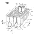
- Fig. 3 is a partially cutaway perspective view showing a package 30 packing therein a plurality of the articles 1A each shown in Fig. 1 and Fig. 4 is a diagram illustrating a manner in which one of the articles 1A is picked up from the package 30.
- a transverse direction is indicated by an arrow X
- a longitudinal direction is indicated by an arrow Y
- a back-and-forth direction is indicated by an arrow Z.
- the package 30 is indicated by imaginary lines.
- the package 30 is made of plastic film and comprises top and bottom walls 30a, 30b and four side walls 30c so as to define a rectangular parallelepiped which is relatively long in the back-and-forth direction.
- the top wall 30a of the package 30 is formed with a handgrip 31.
- the sixteen articles 1A are compactly packed.
- each pair of the articles 1A adjacent to each other in the back-and-forth direction are held in contact with each other over remaining zones 22 except for the first and second zones 17, 18 in the respective articles 1A.
- these articles 1A are held in contact one with another on the outer surfaces of the backsheets 3.
- these articles 1A are packed under compression in the back-and-forth direction and a force in a range of 10 to 75 N is exerted between opposite ends 32a, 32b of the row 32 inward in the back-and-forth direction (i.e., inward in one direction).
- the force exerted between the opposite ends 32a, 32b of the row 32 inward in the back-and-forth direction is preferably in a range of 20 to 45 N.
- the top wall 30a of the package 30 may be broken as illustrated in Fig. 4, then one of the articles 1A in the row 32 may be finger-gripped and pulled out upward from the package 30.
- the side wall 30c of the package 30 may be broken, then one of the articles 1A in the row 32 may be finger-gripped and pulled out laterally from the package 30.
- the row 32 is apt to lean forward or rearward within the package 30 and, when a plurality of the packages 30 are stacked in the vertical direction, such stack of the packages 30 may unintentionally collapse. If the force exceeds 75 N, it is impossible to pull the article 1A smoothly out from the associated row 32.
- the force exerted inward in the back-and-forth direction (inward in one direction) between opposite ends 32a, 32b of the row 32 was measured in a manner as follows: (1) Eight articles 1A with the first and second zones 17, 18 tucked inward were arranged in the back-and-forth direction (in one direction) to form the row 32 and left for 24 hours in a state of nature without exerting a force between the opposite ends 32a, 32b of the row 32 inward in the back-and-forth direction (inward in one direction). In this row 32, the articles 1A were in contact one with another in the remaining zones 22 except for the first and second zones 17, 18.
- the row 32 in which a force is not exerted inward in the back-and-forth direction (inward in one direction) had a dimension measured in the back-and-forth direction larger than a dimension of the package 30 in the back-and-forth direction; (2) After left for 24 hours, a pair of plates were placed at the opposite ends 32a, 32b of the row 32, respectively, so as to sandwich the row 32.
- acryl plates each having a surface area larger than the exposed area of the article 1A so that the plates may compress the entire exposed area of the remaining zone 22 of the article 1A.
- the dimension of the row 32 measured in the back-and-forth dimension when it exactly coincides with the dimension of the package 30 measured in the back-and forth direction refers to the dimension defined between the pair of acryl plates.
- a force necessary to pull the article 1A out from the row 32 was measured in a manner as follows: (1) Eight article 1A with the first and second zones 17, 18 tucked inward were packed within the package 30 so as to be placed one against another in the back-and-forth direction (in one direction). Within the package 30, the remaining zones 22 of the eight articles 1A except for the first and second zones 17, 18 were in contact one with another in the back-and-forth direction to form the row 32, in the same manner as the case illustrated in Figs. 3 and 4.
- a force in a range of 10 to 75 N was exerted inward in the back-and-forth direction from the opposite ends 32a, 32b of the row 32; (2) A single article 1A was selected from the row 32 and the waist-surrounding end zones 8, 9 were gripped by a chuck of a tensile tester; (3) The article 1A gripped by the chuck was pulled out from the row 32 toward above the package 30 by means of the tensile tester and a force required to pull the article 1A out from the row 32 was measured by the tensile tester; and (4) As the tensile tester, INSTRON 5564 (supplied from INSTRON CORP.) was used. A test speed of the tensile tester was 10 mm/min. It should be understood that the maximum value obtained under the measurement condition as set forth above was defined as the force necessary to draw the article 1A out from the row 32.
- the package 30 contains therein a plurality of the articles 1A each having the first and second zones 17, 18 tucked so that an area over which each pair of the adjacent articles 1A held in contact with each other may be reduced and correspondingly a frictional force generated between these adjacent articles 1A may be alleviated compared to the case in which a plurality of articles 1A are packed in the package 30 without being tucked. It is possible to pull the article 1A with a force of 18 N or lower, particularly, to pull the first article 1A out from the row 32 easily regardless of the fact that a force in a range of 10 to 75 N is exerted inward in the back-and-forth direction between the opposite ends 32a, 32b of the row 32.
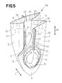
- Fig. 5 is a perspective view showing a wearing article 1B according to an alternative embodiment of the invention with its front waist region 5 partially cut away
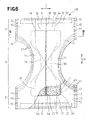
- Fig. 6 is a partially cutaway developed plan view showing the article 1B with its transversely opposite lateral zones 10 disconnected
- Fig. 7 is a sectional view taken along a line VII-VII in Fig. 6.
- a transverse direction is indicated by an arrow L
- a longitudinal direction is indicated by an arrow M
- a leg-surrounding direction is indicated by an arrow N (only in Fig. 5).
- the article 1B comprises a liquid-pervious topsheet 2, a liquid-impervious backsheet 3 and a liquid-absorbent core 4 interposed between these sheets 2, 3 and attached to the inner surface of at least one of these sheets 2, 3 so as to define a front region 5, a rear waist region 7 and a crotch region 6 extending between these waist regions 5, 7.
- the article 1B is formed with a pair of first longitudinal fold guiding lines 15 and a pair of second longitudinal fold guiding lines 16.
- the article 1B is folded along the first fold guiding lines 15 and the second fold guiding lines 16, and a first zone 17 defined between a pair of the first fold guiding lines 15 and a second zone 17 defined between a pair of the second fold guiding lines 16 are tucked inwardly of the article 1B along the first and second fold guiding lines 15, 16.
- the article 1B is distinguished from the article 1A shown in Fig. 1 in that the core 4 is formed with a longitudinal fold guiding zone 23.
- the fold guiding zone 23 extends in the longitudinal direction in coincidence with the imaginary fold guiding line 19 bisecting respective widths of the first and second zones 17, 18.
- the core 4 has a basis weight lower than that in a remaining zone 24 of the core 4 except for the fold guiding zone 23 and has stiffness lower than that in the remaining zone 24 of the core 4.
- the core 4 is folded along the fold guiding zone 23 as the first and second zones 17, 18 are tucked inwardly of the article 1B.
- the fold guiding zone 23 facilitates the first and second zones 17, 18 to be tucked, on one hand, and prevents the first and second zones 17, 18 from being readily unfolded, on the other hand.
- Fig. 8 is a partially cutaway perspective view showing a package 30 packing therein a plurality of the articles 1B each shown in Fig. 5.
- a transverse direction is indicated by an arrow X
- a longitudinal direction is indicated by an arrow Y
- a back-and-forth direction is indicated by an arrow Z.
- sixteen articles 1B are compactly packed.
- each pair of the articles 1B adjacent to each other in the back-and-forth direction are held in contact with each other over remaining zones 22 except for the first and second zones 17, 18 in the respective articles 1B.
- a force in a range of 10 to 75 N is exerted inward in the back-and-forth direction (inward in one direction) between the opposite ends 32a, 32b of the row 32 and a force required to pull one article 1B out from the row 32 of the articles 1B packed therein is 18 N or lower and a force required to pull the first article 1B out from the row 32 is in a range of 18 to 15 N.
- the force exerted inward in the back-and-forth direction (inward in one direction) between the opposite ends 32a, 32b of the row 32 as well as the force required to pull one of the articles 1B from the row 32 were measured by the method as has previously been described.
- the package 30 contains therein a plurality of the articles 1B each having the first and second zones 17, 18 tucked so that an area over which each pair of the adjacent articles 1B held in contact with each other may be reduced and correspondingly a frictional force generated between these adjacent articles 1B may be alleviated compared to the case in which a plurality of articles 1B are packed in the package 30 without being tucked. It is possible to pull the article 1B with the force of 18 N or lower, particularly, to pull the first article 1B out from the row 32 easily regardless of the fact that a force in a range of 10 to 75 N is exerted inward in the back-and-forth direction between the opposite ends of the row 32.
- the number of the articles 1A or 1B to be packed within the package 30 is not limited to sixteen so far as a plurality of the articles 1A or 1B (eight or more articles 1A or 1B) form the row 32 in one direction.
- the force necessary to pull the article 1A or 1B out from the row 32 was measured by pulling the article 1A or 1B gripped by the chuck out from the row 32 toward above the package 30 using the tensile tester, it is also possible to measure the force by pulling the article 1A or 1B gripped by the chuck out from the row 32 laterally of the package 30 using the tensile tester.
- the force required to pull one of the articles 1A or 1B out from the row 32 is 18 N or lower and the force required to pull the first article 1A or 1B out from the row 32 is in a range of 18 to 15 N.
- a stock material for the topsheet 2 may be selected from the group consisting of a hydrophilic fibrous nonwoven fabric, a hydrophobic fibrous nonwoven fabric having a plurality of apertures and a plastic film having a plurality of fine perforations.
- a stock material for the backsheet 3 may be selected from the group consisting of a hydrophobic fibrous nonwoven fabric, a breathable but liquid-impervious plastic film, a composite nonwoven fabric comprising two or more hydrophobic fibrous nonwoven fabric layers laminated one upon another and a composite sheet comprising a hydrophobic fibrous nonwoven fabric and a breathable but liquid-impervious plastic film laminated upon each other.
- a composite nonwoven fabric comprising a melt blown fibrous nonwoven fabric having a high water-resistance interposed between two layers of spun bond fibrous nonwoven fabric being high in strength as well as in flexibility.
- the nonwoven fabric may be selected from the group consisting of those obtained by spun lace-, needle punch-, melt blown-, thermal bond-, spun bond-, chemical bond- and air-through-processes.
- the component fibers of the nonwoven fabric may be selected from the group consisting of polyolefin-, polyester- and polyamide-based fibers, core-sheath type or side-by-side conjugated fibers of polyethylene/polypropylene or polyethylene/polyester.
- the core 4 is a mixture of fluff pulp and super-absorbent polymer particles or a mixture of fluff pulp, super-absorbent polymer particles and thermoplastic synthetic resin fibers, in both cases, compressed to a desired thickness.
- the core 4 is entirely wrapped with a liquid-pervious sheet such as a tissue paper or a hydrophilic fibrous nonwoven fabric to prevent the core 4 from getting out of its initial shape and to prevent polymer particles from falling off.
- the polymer particles may be selected from the group consisting of those of starch-based polymer, cellulose-based polymer and synthetic polymer.
- a basis weight of fluff pulp and thermoplastic resin fibers constituting the core 4 in the fold guiding zone 23 may be made lower than that in the remaining zone 24 except for the fold guiding zone 23.
- the steps of joining the top- and backsheets 2, 3 to each other, attaching the core 4 to these sheets 2, 3 and attaching the elastic members 20, 21 to these sheets 2, 3 may be carried out using a hot melt adhesive or various thermal welding techniques such as a heat-sealing and an ultrasonic sealing.
- the pull-on disposable wearing article according to the present invention is primarily characterized in that the first and second zones are tucked inwardly of the article along the first and second fold guiding lines so that the article can be made compact.
- the leg-holes remain opened, it is unnecessary to broaden the leg-holes in order to guide the wearer's legs through the leg-holes and any troublesome handling can be avoided when the article is put on the wearer' s body.
- the core is folded along this fold guiding zone as the first and second zones are tucked inward of the article.
- the fold guiding zone facilitates the first and second zones to be tucked, on one hand, and prevents the first and second zones from being readily unfolded, on the other hand.
Landscapes
- Health & Medical Sciences (AREA)
- General Health & Medical Sciences (AREA)
- Epidemiology (AREA)
- Biomedical Technology (AREA)
- Heart & Thoracic Surgery (AREA)
- Vascular Medicine (AREA)
- Life Sciences & Earth Sciences (AREA)
- Engineering & Computer Science (AREA)
- Public Health (AREA)
- Animal Behavior & Ethology (AREA)
- Veterinary Medicine (AREA)
- Absorbent Articles And Supports Therefor (AREA)
- Orthopedics, Nursing, And Contraception (AREA)
- Bag Frames (AREA)
- Packages (AREA)
- Professional, Industrial, Or Sporting Protective Garments (AREA)
Abstract
An article 1A is formed with a pair of first longitudinal
fold guiding lines 15 and a pair of second longitudinal fold
guiding lines 16. A first zone 17 defined between the first
fold guiding lines 15 is tucked inwardly of the article 1A along
the first fold guiding lines 15 and a second zone 18 defined
between the second fold guiding lines 16 is tucked inwardly of
the article 1A along the second fold guiding lines 16.
Leg-holes 14 remain opened.
Description
The present invention relates to a pull-on disposable
wearing article adapted to absorb and to retain bodily
discharges.
There has already been proposed a pull-on disposable
wearing article defining front and rear waist regions opposed
to each other and a crotch region extending between these waist
regions, on one hand, and comprising a liquid-pervious topsheet,
a liquid-impervious backsheet and a liquid-absorbent core
interposed between these sheets so as to form a waist-hole and
a pair of leg-holes lying below the waist-hole, on the other
hand, for example, by Japanese Patent Application Publication
Nos. 1999-104177A and 1999-155904A.
The pull-on disposable articles disclosed in the
above-cited Publication is folded in two in the crotch region
so that the respective inner surfaces of the front and rear waist
regions may come in contact with each other. A set of about
16 to 48 individual articles is orderly and compactly packed
in a package and sold per such package. For example, when 16
diapers are packed in the package, eight articles are placed
one against another to form a row extending in a back-and-forth
direction and a pair of such rows are stacked in a vertical
direction or arranged side by side. In each of these rows, each
pair of the articles adjacent in the back-and-forth direction,
substantially entire outer surface defined by the front and rear
waist regions and the crotch region of the one article is in
contact with the corresponding entire outer surface of the other
article. When it is desired to pick up one of these articles,
the top wall of the package may be broken and the target one
article may be finger-gripped and pulled out from the package
toward above the package.
Within the package, the article disclosed by the
above-cited Publication is folded in two so that the respective
inner surfaces of the front and rear waist regions may come in
contact with each other and, in consequence, lateral zones of
the crotch region destined to define the respective leg-holes
are also folded in two and overlaid so as to close the respective
leg-holes. To put the article folded in such state on the
wearer's body, it is necessary to broaden the respective
leg-holes as the wearer's legs are guided through these
leg-holes and therefore a troublesome handling is required to
put the article on the wearer's body.
In addition, within the package packing a plurality of
the articles as disclosed by the above-cited Publication, these
articles are compressed together in the back-and-forth
direction under a pressure in a range of approximately 15 to
70 N exerted thereon in the back-and-forth direction from
longitudinally opposite ends of the row. As a result, a
predetermined force is required to pull one of the articles out
from the row. These articles are held in contact one with
another substantially over the entire outer surface defined by
the front and rear waist regions and the crotch region of each
of the articles. In other words, the contact area between each
pair of the articles adjacent in the back-and-forth direction
is relatively large and a frictional force between these
articles is correspondingly high. Inconveniently, a force in
a range of 20 to 22 N is required to pull the first article out
from the row.
It is an object of the present invention to provide a
pull-on disposable wearing article improved so that wearer's
legs can be easily guided through respective leg-holes, on one
hand, and each of the articles in any one row packed in a package
can be easily pulled out from the row.
According to the present invention, there is provided a
pull-on disposable wearing article having front and rear waist
regions opposed to each other and a crotch region extending
between the waist regions connected to each other along
transversely opposite lateral zones thereof so as to form a
waist-hole and a pair of leg-holes.
The improvement according to the present invention is
characterized by that the article is formed with a pair of first
longitudinal fold guiding lines extending from a transversely
middle zone of the crotch region so as to be spaced apart from
each other and further extending in a longitudinal direction
over a transversely middle zone of the front waist region and
a pair of second longitudinal fold guiding lines extending from
the transversely middle zone of the crotch region so as to be
spaced apart from each other and further extending in the
longitudinal direction over a transversely middle zone of the
rear waist region; and a first zone defined between the first
fold guiding lines is tucked inwardly of the article along the
first fold guiding lines and a second zone defined between the
second fold guiding lines is tucked inwardly of the article.
According to one preferred embodiment of the present
invention, the article comprises a liquid-pervious topsheet
facing a wearer's body, a liquid-impervious backsheet facing
away from the wearer's body and a liquid-absorbent core
interposed between these sheets and extending over said crotch
region into the front and rear waist regions.
According to another preferred embodiment of the present
invention, the core is formed with a longitudinal fold guiding
zone extending in the first and second zones and the core has
a stiffness lower in the fold guiding zone than in the remaining
zone of the core except for the fold guiding zone.
According to still another preferred embodiment of the
present invention, a plurality of the articles are compactly
packed in a package within which the articles are placed one
against another in one direction to form a row so that each pair
of the articles adjacent to each other in the one direction are
held in contact with each other over respective zones except
for said first and second zones, within the package, a force
in a range of 10 to 75 N is exerted inward in one direction between
opposite ends of the row and a force of 18 N or lower is enough
to pull one of the articles out from the row. "A plurality of
the articles" is used to refer to approximately eight or more
articles.
Details of the pull-on disposable wearing article
according to the present invention will be more fully understood
from the description given hereunder with reference to the
accompanying drawings.
Fig. 1 is a perspective view showing a wearing article
1A according to the present invention and Fig. 2 is a partially
cutaway developed plan view showing the article 1A, in which
its front and rear waist regions are disconnected from each
other along transversely opposite lateral zones 10 of these
waist regions. In Figs. 1 and 2, a transverse direction is
indicated by an arrow L, a longitudinal direction is indicated
by an arrow M and a leg-surrounding direction is indicated by
an arrow N (only in Fig. 1). Expression "inner surfaces of top-and
backsheets 2, 3" refers to the surfaces of the respective
sheets 2, 3 facing a core 4 and expression "outer surfaces of
these sheets 2, 3" refers to the surfaces of the respective
sheets 2, 3 facing away from the core 4.
The article 1A comprises the liquid-pervious topsheet 2,
the liquid-impervious backsheet 3 and the liquid-absorbent core
4 interposed between these sheets 2, 3 and attached to the inner
surface of at least one of these sheets 2, 3.
The article 1A has a front region 5, a rear waist region
7 and a crotch region 6 extending between these waist regions
5, 7. The core 4 extends from the crotch region 6 toward the
front and rear waist regions 5, 7. The article 1A is contoured
by upper end zones 8, 9 of the front and rear waist regions 5,
7 extending outside longitudinally opposite ends 4a, 4a of the
core 4 in the transverse direction, transversely opposite
lateral zones 10 of the front and rear waist regions 5, 7
extending outside transversely opposite side edges 4b, 4b of
the core 4 in the longitudinal direction, and lateral zones 11
of the crotch region 6 extending outside the transversely
opposite side edges 4b of the core 4 in the leg-surrounding
direction.
In the article 1A, the respective waist lateral zones 10
of the front and rear waist regions 5, 7 are overlaid and joined
together by a plurality of heat-sealing lines 12 arranged
intermittently along the respective lateral zones 10 in the
longitudinal direction. The article 1A is formed with a
waist-hole 13 and a pair of leg-holes 14 lying below the
waist-hole 13. The respective leg-surrounding lateral zones
11 of the crotch region 6 describe circular arcs which are convex
inward in the transverse direction of the article 1A. The
article 1A presents a substantially hourglass-like planar
shape.
As will be seen in Fig. 2, the article 1A is formed with
a pair of first longitudinal fold guiding lines 15 and a pair
of second longitudinal fold guiding lines 16. The first fold
guiding lines 15 extend from a transversely middle zone 6a of
the crotch region 6 so as to be spaced apart from each other
and further extend in the longitudinal direction parallel to
each other in a transversely middle zone 5a of the front waist
region 5. The first fold guiding lines 15 extend from the
crotch region 6 to the waist-surrounding end zone 8 of the front
waist region 5 over the transversely middle zone 5a of the front
waist region 5. The second fold guiding lines 16 extend from
the transversely middle zone 6a of the crotch region 6 so as
to be spaced apart from each other and extend longitudinally
parallel to each other in a transversely middle zone 7a of the
rear waist region 7. The second fold guiding lines 16 extend
from the crotch region 6 to the waist-surrounding end zone 9
of the rear waist region 7 over the transversely middle zone
7 of the rear waist region 7. The first and second fold guiding
lines 15, 16 are converged at the transversely middle zone 6a
of the crotch region 6.
A first zone 17 is defined between the first fold guiding
lines 15 and extends in the longitudinal direction. Similarly,
a second zone 18 is defined between the second fold guiding lines
16 and extends in the longitudinal direction. The first zone
17 is tucked inwardly of the article 1A along the first fold
guiding lines 15 so that the outer surface of the backsheet 3
in this first zone 17 is opposed to itself and the first zone
17 gets near to the rear waist region 7. The second zone 18
is tucked inwardly of the article 1A along the second fold
guiding lines 16 so that the outer surface of the backsheet 3
in this second zones 18 is opposed to itself and the second zone
18 gets near to the front waist region 5. In the first and second
zones 17, 18, an imaginary fold guiding line 19 bisecting
respective widths of the first and second zones 17, 18 lies.
Band-like waist elastic members 20 are attached to the
respective waist-surrounding end zones 8, 9 so that these
elastic members 20 extend in the transverse direction and can
contract in this direction. A plurality of leg elastic members
21 are attached to each of the leg-surrounding lateral zones
11 so that these elastic members 21 extend in the
leg-surrounding direction and can contract in this direction.
These elastic members 20, 21 are interposed between the top-and
backsheets 2, 3 and bonded to the inner surface of at least
one of these sheets 2, 3. Along the waist-surrounding end zones
8, 9, the waist lateral zones 10 and the leg-surrounding lateral
zones 11, the top- and backsheets 2, 3 are overlaid and have
the respective inner surfaces intermittently joined together.
Tucking of the first and second zones 17, 18 inwardly of
the article 1A along the first and second fold guiding lines
15, 16 allows the article 1A to be made substantially compact.
In the article 1A in which the first and second zones 17, 18
are tucked inwardly of the article 1A, the leg-surrounding
lateral zones 11 are not overlaid and the leg-holes 14 remain
opened. With the article 1A in which the leg-holes 14 are opened,
it is unnecessary to open out these leg-holes 14 when the
wearer's legs are guided through these leg-holes 14 and it is
not likely that any troublesome handling might be required to
put the article 1A on the wearer's body.
Fig. 3 is a partially cutaway perspective view showing
a package 30 packing therein a plurality of the articles 1A each
shown in Fig. 1 and Fig. 4 is a diagram illustrating a manner
in which one of the articles 1A is picked up from the package
30. In Figs. 3 and 4, a transverse direction is indicated by
an arrow X, a longitudinal direction is indicated by an arrow
Y and a back-and-forth direction is indicated by an arrow Z.
In Fig. 4, the package 30 is indicated by imaginary lines.
The package 30 is made of plastic film and comprises top
and bottom walls 30a, 30b and four side walls 30c so as to define
a rectangular parallelepiped which is relatively long in the
back-and-forth direction. The top wall 30a of the package 30
is formed with a handgrip 31. Within the package 30, the sixteen
articles 1A are compactly packed.
Within the package 30, eight articles 1A are placed one
against another in the back-and-forth direction so as to form
a row 32 and a pair of the rows 32 are packed side by side. In
each of the rows 32, each pair of the articles 1A adjacent to
each other in the back-and-forth direction are held in contact
with each other over remaining zones 22 except for the first
and second zones 17, 18 in the respective articles 1A. In the
remaining zones 22, these articles 1A are held in contact one
with another on the outer surfaces of the backsheets 3.
Within the package 30, these articles 1A are packed under
compression in the back-and-forth direction and a force in a
range of 10 to 75 N is exerted between opposite ends 32a, 32b
of the row 32 inward in the back-and-forth direction (i.e.,
inward in one direction). The force exerted between the
opposite ends 32a, 32b of the row 32 inward in the back-and-forth
direction is preferably in a range of 20 to 45 N. To pick up
one of these articles 1A from the package 30, the top wall 30a
of the package 30 may be broken as illustrated in Fig. 4, then
one of the articles 1A in the row 32 may be finger-gripped and
pulled out upward from the package 30. Alternatively, the side
wall 30c of the package 30 may be broken, then one of the articles
1A in the row 32 may be finger-gripped and pulled out laterally
from the package 30.
If the force is lower than 10 N, the row 32 is apt to lean
forward or rearward within the package 30 and, when a plurality
of the packages 30 are stacked in the vertical direction, such
stack of the packages 30 may unintentionally collapse. If the
force exceeds 75 N, it is impossible to pull the article 1A
smoothly out from the associated row 32.
The force exerted inward in the back-and-forth direction
(inward in one direction) between opposite ends 32a, 32b of the
row 32 was measured in a manner as follows: (1) Eight articles
1A with the first and second zones 17, 18 tucked inward were
arranged in the back-and-forth direction (in one direction) to
form the row 32 and left for 24 hours in a state of nature without
exerting a force between the opposite ends 32a, 32b of the row
32 inward in the back-and-forth direction (inward in one
direction). In this row 32, the articles 1A were in contact
one with another in the remaining zones 22 except for the first
and second zones 17, 18. The row 32 in which a force is not
exerted inward in the back-and-forth direction (inward in one
direction) had a dimension measured in the back-and-forth
direction larger than a dimension of the package 30 in the
back-and-forth direction; (2) After left for 24 hours, a pair
of plates were placed at the opposite ends 32a, 32b of the row
32, respectively, so as to sandwich the row 32. Then a plurality
of the articles 1A were compressed by the plates inward in the
back-and-forth direction (inward in one direction) until the
dimension of the row 32 measured in the back-and-forth direction
exactly coincided with the dimension of the package 30 measured
in the back-and-forth direction; (3) A force exerted upon the
plates when the dimension of the row 32 measured in the
back-and-forth direction exactly coincides with the dimension
of the package 30 measured in the back-and-forth direction was
measured by a compression tester; and (4) as the compression
tester, INSTRON 5564 (supplied from INSTRON CORP.) was used.
A test speed of this compression tester was 10 mm/min. As the
plates, acryl plates each having a surface area larger than the
exposed area of the article 1A so that the plates may compress
the entire exposed area of the remaining zone 22 of the article
1A. It should be understood here that the dimension of the row
32 measured in the back-and-forth dimension when it exactly
coincides with the dimension of the package 30 measured in the
back-and forth direction refers to the dimension defined
between the pair of acryl plates.
In the case of this package 30, a force of 18 N or lower
is enough to pull one of the articles 1A out from the row 32
and a force in a range of 15 to 18 N is enough to pull the first
article 1A out from the row 32. If a force higher than 18 N
is necessary to pull one of the articles 1A out from the row
32, the article 1A could not be smoothly pulled out from the
package 30 unless the article 1A is pull with a considerably
high force. In addition to such inconvenience, there is a
possibility that one or two articles 1A adjacent to the target
article 1A might be pulled out from the row 32 as the target
article 1A is pulled out from the row 32.
A force necessary to pull the article 1A out from the row
32 was measured in a manner as follows: (1) Eight article 1A
with the first and second zones 17, 18 tucked inward were packed
within the package 30 so as to be placed one against another
in the back-and-forth direction (in one direction). Within the
package 30, the remaining zones 22 of the eight articles 1A
except for the first and second zones 17, 18 were in contact
one with another in the back-and-forth direction to form the
row 32, in the same manner as the case illustrated in Figs. 3
and 4. Within the package 30, a force in a range of 10 to 75
N was exerted inward in the back-and-forth direction from the
opposite ends 32a, 32b of the row 32; (2) A single article 1A
was selected from the row 32 and the waist-surrounding end zones
8, 9 were gripped by a chuck of a tensile tester; (3) The article
1A gripped by the chuck was pulled out from the row 32 toward
above the package 30 by means of the tensile tester and a force
required to pull the article 1A out from the row 32 was measured
by the tensile tester; and (4) As the tensile tester, INSTRON
5564 (supplied from INSTRON CORP.) was used. A test speed of
the tensile tester was 10 mm/min. It should be understood that
the maximum value obtained under the measurement condition as
set forth above was defined as the force necessary to draw the
article 1A out from the row 32.
The package 30 contains therein a plurality of the
articles 1A each having the first and second zones 17, 18 tucked
so that an area over which each pair of the adjacent articles
1A held in contact with each other may be reduced and
correspondingly a frictional force generated between these
adjacent articles 1A may be alleviated compared to the case in
which a plurality of articles 1A are packed in the package 30
without being tucked. It is possible to pull the article 1A
with a force of 18 N or lower, particularly, to pull the first
article 1A out from the row 32 easily regardless of the fact
that a force in a range of 10 to 75 N is exerted inward in the
back-and-forth direction between the opposite ends 32a, 32b of
the row 32.
Fig. 5 is a perspective view showing a wearing article
1B according to an alternative embodiment of the invention with
its front waist region 5 partially cut away, Fig. 6 is a partially
cutaway developed plan view showing the article 1B with its
transversely opposite lateral zones 10 disconnected and Fig.
7 is a sectional view taken along a line VII-VII in Fig. 6. In
Figs. 5 and 6, a transverse direction is indicated by an arrow
L, a longitudinal direction is indicated by an arrow M and a
leg-surrounding direction is indicated by an arrow N (only in
Fig. 5).
The article 1B comprises a liquid-pervious topsheet 2,
a liquid-impervious backsheet 3 and a liquid-absorbent core 4
interposed between these sheets 2, 3 and attached to the inner
surface of at least one of these sheets 2, 3 so as to define
a front region 5, a rear waist region 7 and a crotch region 6
extending between these waist regions 5, 7. As will be seen
in Fig. 6, the article 1B is formed with a pair of first
longitudinal fold guiding lines 15 and a pair of second
longitudinal fold guiding lines 16.
The article 1B is folded along the first fold guiding
lines 15 and the second fold guiding lines 16, and a first zone
17 defined between a pair of the first fold guiding lines 15
and a second zone 17 defined between a pair of the second fold
guiding lines 16 are tucked inwardly of the article 1B along
the first and second fold guiding lines 15, 16.
The article 1B is distinguished from the article 1A shown
in Fig. 1 in that the core 4 is formed with a longitudinal fold
guiding zone 23. The fold guiding zone 23 extends in the
longitudinal direction in coincidence with the imaginary fold
guiding line 19 bisecting respective widths of the first and
second zones 17, 18. In the fold guiding zone 23, the core 4
has a basis weight lower than that in a remaining zone 24 of
the core 4 except for the fold guiding zone 23 and has stiffness
lower than that in the remaining zone 24 of the core 4.
In the case of the article 1B, the core 4 is folded along
the fold guiding zone 23 as the first and second zones 17, 18
are tucked inwardly of the article 1B. In this way, the fold
guiding zone 23 facilitates the first and second zones 17, 18
to be tucked, on one hand, and prevents the first and second
zones 17, 18 from being readily unfolded, on the other hand.
Tucking of the first and second zones 17, 18 inwardly of
the article 1B along the first and second fold guiding lines
15, 16 allows the article 1B to be made compact. In the article
1B in which the first and second zones 17, 18 are tucked inwardly
of the article 1B along the first and second fold guiding lines
17, 18, as will be seen in Fig. 5, and the leg-holes 14 remain
opened and it is not likely that any troublesome handling might
be required to put the article 1B on the wearer's body because
it is unnecessary to open out these leg-holes 14 when the
wearer's legs are guided through these leg-holes 14.
Fig. 8 is a partially cutaway perspective view showing
a package 30 packing therein a plurality of the articles 1B each
shown in Fig. 5. In Fig. 8, a transverse direction is indicated
by an arrow X, a longitudinal direction is indicated by an arrow
Y and a back-and-forth direction is indicated by an arrow Z.
Within the package 30, sixteen articles 1B are compactly packed.
Within the package 30, eight articles 1B are placed one
against another in the back-and-forth direction so as to form
a row 32 and a pair of rows 32 are packed side by side. In each
of the rows 32, each pair of the articles 1B adjacent to each
other in the back-and-forth direction (in one direction) are
held in contact with each other over remaining zones 22 except
for the first and second zones 17, 18 in the respective articles
1B.
Within the package 30, a force in a range of 10 to 75 N
is exerted inward in the back-and-forth direction (inward in
one direction) between the opposite ends 32a, 32b of the row
32 and a force required to pull one article 1B out from the row
32 of the articles 1B packed therein is 18 N or lower and a force
required to pull the first article 1B out from the row 32 is
in a range of 18 to 15 N. The force exerted inward in the
back-and-forth direction (inward in one direction) between the
opposite ends 32a, 32b of the row 32 as well as the force required
to pull one of the articles 1B from the row 32 were measured
by the method as has previously been described.
The package 30 contains therein a plurality of the
articles 1B each having the first and second zones 17, 18 tucked
so that an area over which each pair of the adjacent articles
1B held in contact with each other may be reduced and
correspondingly a frictional force generated between these
adjacent articles 1B may be alleviated compared to the case in
which a plurality of articles 1B are packed in the package 30
without being tucked. It is possible to pull the article 1B
with the force of 18 N or lower, particularly, to pull the first
article 1B out from the row 32 easily regardless of the fact
that a force in a range of 10 to 75 N is exerted inward in the
back-and-forth direction between the opposite ends of the row
32.
While sixteen articles 1A or 1B are packed within the
package 30, the number of the articles 1A or 1B to be packed
within the package 30 is not limited to sixteen so far as a
plurality of the articles 1A or 1B (eight or more articles 1A
or 1B) form the row 32 in one direction.
While the force necessary to pull the article 1A or 1B
out from the row 32 was measured by pulling the article 1A or
1B gripped by the chuck out from the row 32 toward above the
package 30 using the tensile tester, it is also possible to
measure the force by pulling the article 1A or 1B gripped by
the chuck out from the row 32 laterally of the package 30 using
the tensile tester. In this case also, the force required to
pull one of the articles 1A or 1B out from the row 32 is 18 N
or lower and the force required to pull the first article 1A
or 1B out from the row 32 is in a range of 18 to 15 N.
A stock material for the topsheet 2 may be selected from
the group consisting of a hydrophilic fibrous nonwoven fabric,
a hydrophobic fibrous nonwoven fabric having a plurality of
apertures and a plastic film having a plurality of fine
perforations. A stock material for the backsheet 3 may be
selected from the group consisting of a hydrophobic fibrous
nonwoven fabric, a breathable but liquid-impervious plastic
film, a composite nonwoven fabric comprising two or more
hydrophobic fibrous nonwoven fabric layers laminated one upon
another and a composite sheet comprising a hydrophobic fibrous
nonwoven fabric and a breathable but liquid-impervious plastic
film laminated upon each other. It is also possible to use,
as a stock material for the backsheet 3, a composite nonwoven
fabric comprising a melt blown fibrous nonwoven fabric having
a high water-resistance interposed between two layers of spun
bond fibrous nonwoven fabric being high in strength as well as
in flexibility.
The nonwoven fabric may be selected from the group
consisting of those obtained by spun lace-, needle punch-, melt
blown-, thermal bond-, spun bond-, chemical bond- and
air-through-processes. The component fibers of the nonwoven
fabric may be selected from the group consisting of polyolefin-,
polyester- and polyamide-based fibers, core-sheath type or
side-by-side conjugated fibers of polyethylene/polypropylene
or polyethylene/polyester.
The core 4 is a mixture of fluff pulp and super-absorbent
polymer particles or a mixture of fluff pulp, super-absorbent
polymer particles and thermoplastic synthetic resin fibers, in
both cases, compressed to a desired thickness. Preferably, the
core 4 is entirely wrapped with a liquid-pervious sheet such
as a tissue paper or a hydrophilic fibrous nonwoven fabric to
prevent the core 4 from getting out of its initial shape and
to prevent polymer particles from falling off. The polymer
particles may be selected from the group consisting of those
of starch-based polymer, cellulose-based polymer and synthetic
polymer. To reduce a basis weight of the core 4 in the fold
guiding zone 23, a basis weight of fluff pulp and thermoplastic
resin fibers constituting the core 4 in the fold guiding zone
23 may be made lower than that in the remaining zone 24 except
for the fold guiding zone 23.
The steps of joining the top- and backsheets 2, 3 to each
other, attaching the core 4 to these sheets 2, 3 and attaching
the elastic members 20, 21 to these sheets 2, 3 may be carried
out using a hot melt adhesive or various thermal welding
techniques such as a heat-sealing and an ultrasonic sealing.
The pull-on disposable wearing article according to the
present invention is primarily characterized in that the first
and second zones are tucked inwardly of the article along the
first and second fold guiding lines so that the article can be
made compact. In addition, as the leg-holes remain opened, it
is unnecessary to broaden the leg-holes in order to guide the
wearer's legs through the leg-holes and any troublesome
handling can be avoided when the article is put on the wearer' s
body.
In the case of the embodiment in which the core is formed
with the fold guiding zone extending in the longitudinal
direction, the core is folded along this fold guiding zone as
the first and second zones are tucked inward of the article.
In this way, the fold guiding zone facilitates the first and
second zones to be tucked, on one hand, and prevents the first
and second zones from being readily unfolded, on the other hand.
With the package packing therein a plurality of the
articles each having the first and second zones tucked, an area
over which each pair of the adjacent articles held in contact
with each other may be reduced and correspondingly a frictional
force generated between these adjacent articles may be
alleviated compared to the case in which a plurality of the
articles are packed in the package without being tucked.
Consequently, a force of 18 N or lower is enough to pull the
article, particularly, the first article out from the row of
the articles regardless of the fact that a force in a range of
10 to 75 N is exerted inward in the back-and-forth direction
from the opposite ends of the row.
Claims (4)
- A pull-on disposable wearing article having front and rear waist regions opposed to each other and a crotch region extending between said waist regions connected to each other along transversely opposite lateral zones thereof so as to form a waist-hole and a pair of leg-holes, said pull-on disposable wearing article being characterized by that:said article is formed with a pair of first longitudinal fold guiding lines extending from a transversely middle zone of said crotch region so as to be spaced apart from each other and further extending in a longitudinal direction over a transversely middle zone of said front waist region and a pair of second longitudinal fold guiding lines extending from said transversely middle zone of said crotch region so as to be spaced apart from each other and further extending in said longitudinal direction over a transversely middle zone of said rear waist region; anda first zone defined between said first fold guiding lines is tucked inwardly of said article along said first fold guiding lines and a second zone defined between said second fold guiding lines is tucked inwardly of said article.
- The wearing article according to Claim 1, wherein said article comprises a liquid-pervious topsheet facing a wearer's body, a liquid-impervious backsheet facing away from said wearer's body and a liquid-absorbent core interposed between said sheets and extending over said crotch region into said front and rear waist regions.
- The wearing article according to Claim 2, wherein said core is formed with a longitudinal fold guiding zone extending in said first and second zones and said core has a stiffness lower in said fold guiding zone than in the remaining zone of said core except for said fold guiding zone.
- The wearing article according to any one of Claims 1 through 3, wherein a plurality of said articles are compactly packed in a package within which said articles are placed one against another in one direction to form a row so that each pair of said articles adjacent to each other in said one direction are held in contact with each other over respective zones except for said first and second zones, within said package, a force in a range of 10 to 75 N is exerted inward in one direction opposite ends of said row and a force of 18 N or lower is enough to pull one of said articles out from said row.
Applications Claiming Priority (3)
| Application Number | Priority Date | Filing Date | Title |
|---|---|---|---|
| JP2002229351A JP4116837B2 (en) | 2002-08-07 | 2002-08-07 | Pants-type disposable wearing articles |
| JP2002229351 | 2002-08-07 | ||
| PCT/JP2003/009188 WO2004014278A1 (en) | 2002-08-07 | 2003-07-18 | Underpants type disposable wearing article |
Publications (2)
| Publication Number | Publication Date |
|---|---|
| EP1552800A1 true EP1552800A1 (en) | 2005-07-13 |
| EP1552800A4 EP1552800A4 (en) | 2008-02-20 |
Family
ID=31711652
Family Applications (1)
| Application Number | Title | Priority Date | Filing Date |
|---|---|---|---|
| EP03741505A Withdrawn EP1552800A4 (en) | 2002-08-07 | 2003-07-18 | Pull-on disposable wearing article |
Country Status (10)
| Country | Link |
|---|---|
| US (1) | US7147630B2 (en) |
| EP (1) | EP1552800A4 (en) |
| JP (1) | JP4116837B2 (en) |
| KR (1) | KR100624524B1 (en) |
| CN (1) | CN1305453C (en) |
| AU (1) | AU2003281874B2 (en) |
| BR (1) | BR0313374A (en) |
| CA (1) | CA2493930C (en) |
| TW (1) | TW582997B (en) |
| WO (1) | WO2004014278A1 (en) |
Families Citing this family (4)
| Publication number | Priority date | Publication date | Assignee | Title |
|---|---|---|---|---|
| JP5676901B2 (en) * | 2010-03-31 | 2015-02-25 | ユニ・チャーム株式会社 | Disposable pants-type wearing articles |
| JP5329631B2 (en) * | 2011-09-30 | 2013-10-30 | 大王製紙株式会社 | Absorbent articles |
| EP4414290A1 (en) * | 2023-02-09 | 2024-08-14 | The Procter & Gamble Company | Absorbent article packages with natural fibers |
| CN117719243B (en) * | 2023-12-15 | 2026-01-09 | 福建省金嘉华卫生用品有限公司 | A method for preparing low-reverse leakage baby diapers |
Family Cites Families (16)
| Publication number | Priority date | Publication date | Assignee | Title |
|---|---|---|---|---|
| NL299799A (en) * | 1962-11-01 | |||
| US3744494A (en) * | 1970-07-10 | 1973-07-10 | Procter & Gamble | Disposable diaper with improved containment characteristics |
| US3774610A (en) * | 1972-01-03 | 1973-11-27 | Kimberly Clark Co | Prefolded disposable diaper |
| US3924627A (en) * | 1973-06-25 | 1975-12-09 | Paper Converting Machine Co | Disposable diaper |
| US3943930A (en) * | 1974-10-03 | 1976-03-16 | Colgate-Palmolive Company | Disposable diaper |
| US3968799A (en) * | 1975-04-04 | 1976-07-13 | Kimberly-Clark Corporation | Prefolded disposable diaper |
| US4100922A (en) * | 1975-07-09 | 1978-07-18 | Colgate-Palmolive Company | Disposable diaper |
| JPH0321190U (en) * | 1989-07-06 | 1991-03-01 | ||
| JP3021190U (en) * | 1995-08-01 | 1996-02-16 | トーヨー衛材株式会社 | Disposable pants |
| JPH1095481A (en) * | 1996-09-19 | 1998-04-14 | Kao Corp | Individual packaging structure for disposable diapers |
| JP3398024B2 (en) | 1997-09-30 | 2003-04-21 | ユニ・チャーム株式会社 | Disposable training pants |
| JP3492171B2 (en) | 1997-11-28 | 2004-02-03 | ユニ・チャーム株式会社 | Training pants |
| JP3411224B2 (en) * | 1998-09-14 | 2003-05-26 | ユニ・チャーム株式会社 | Disposable diapers |
| JP3652534B2 (en) * | 1998-12-09 | 2005-05-25 | ユニ・チャーム株式会社 | Method for producing disposable trunks-type wearing article |
| CA2316499C (en) * | 1999-08-16 | 2009-02-17 | Johnson & Johnson Inc. | Thin sanitary napkin capable of controlled deformation when in use |
| JP3807924B2 (en) * | 2000-10-31 | 2006-08-09 | ユニ・チャーム株式会社 | Pants-type disposable wearing articles |
-
2002
- 2002-08-07 JP JP2002229351A patent/JP4116837B2/en not_active Expired - Fee Related
-
2003
- 2003-07-18 KR KR1020057001390A patent/KR100624524B1/en not_active Expired - Fee Related
- 2003-07-18 WO PCT/JP2003/009188 patent/WO2004014278A1/en not_active Ceased
- 2003-07-18 CA CA002493930A patent/CA2493930C/en not_active Expired - Fee Related
- 2003-07-18 AU AU2003281874A patent/AU2003281874B2/en not_active Ceased
- 2003-07-18 EP EP03741505A patent/EP1552800A4/en not_active Withdrawn
- 2003-07-18 BR BR0313374-5A patent/BR0313374A/en not_active IP Right Cessation
- 2003-07-18 TW TW092119676A patent/TW582997B/en not_active IP Right Cessation
- 2003-07-18 CN CNB038186985A patent/CN1305453C/en not_active Expired - Fee Related
-
2004
- 2004-11-24 US US10/995,896 patent/US7147630B2/en not_active Expired - Fee Related
Also Published As
| Publication number | Publication date |
|---|---|
| TW200402285A (en) | 2004-02-16 |
| KR100624524B1 (en) | 2006-09-15 |
| AU2003281874B2 (en) | 2008-10-23 |
| AU2003281874A1 (en) | 2004-02-25 |
| US20050070869A1 (en) | 2005-03-31 |
| KR20050025995A (en) | 2005-03-14 |
| US7147630B2 (en) | 2006-12-12 |
| EP1552800A4 (en) | 2008-02-20 |
| WO2004014278A1 (en) | 2004-02-19 |
| CA2493930A1 (en) | 2004-02-19 |
| CN1674845A (en) | 2005-09-28 |
| TW582997B (en) | 2004-04-11 |
| JP2004065600A (en) | 2004-03-04 |
| BR0313374A (en) | 2005-06-21 |
| JP4116837B2 (en) | 2008-07-09 |
| CN1305453C (en) | 2007-03-21 |
| CA2493930C (en) | 2008-02-12 |
Similar Documents
| Publication | Publication Date | Title |
|---|---|---|
| US20040129592A1 (en) | Package of disposable diapers | |
| US7001368B2 (en) | Disposable pull-on wearing article | |
| AU2003239602B2 (en) | Underpants-type disposable wearing article | |
| CA2356101C (en) | Disposable pull-on diaper | |
| US7588561B2 (en) | Pull-on disposable wearing article with tapered folding guide lines and tucking zones | |
| CA2473294C (en) | Packaged assembly of disposable diapers | |
| US7000764B2 (en) | Packaged diapers assembly | |
| US7112189B2 (en) | Pants-type disposable wearing article | |
| US20040195137A1 (en) | Packaged diapers assembly | |
| CA2493930C (en) | Pull-on disposable wearing article | |
| US20040002689A1 (en) | Pull-on disposable wearing article | |
| EP1473007A1 (en) | Pull-on disposable wearing article |
Legal Events
| Date | Code | Title | Description |
|---|---|---|---|
| PUAI | Public reference made under article 153(3) epc to a published international application that has entered the european phase |
Free format text: ORIGINAL CODE: 0009012 |
|
| 17P | Request for examination filed |
Effective date: 20050304 |
|
| AK | Designated contracting states |
Kind code of ref document: A1 Designated state(s): AT BE BG CH CY CZ DE DK EE ES FI FR GB GR HU IE IT LI LU MC NL PT RO SE SI SK TR |
|
| AX | Request for extension of the european patent |
Extension state: AL LT LV MK |
|
| DAX | Request for extension of the european patent (deleted) | ||
| A4 | Supplementary search report drawn up and despatched |
Effective date: 20080123 |
|
| 17Q | First examination report despatched |
Effective date: 20080603 |
|
| STAA | Information on the status of an ep patent application or granted ep patent |
Free format text: STATUS: THE APPLICATION IS DEEMED TO BE WITHDRAWN |
|
| 18D | Application deemed to be withdrawn |
Effective date: 20140806 |