TECHNICAL FIELD
The present invention relates to tennis shoes. More
particularly, the present invention relates to an improvement
in the bottom faces of the tennis shoes.
BACKGROUND ART
In the rally of tennis, a player makes a stroke while
heavily moving in a court. The player predicts the direction
of a ball from the stroke of an opponent and moves toward a target
spot. Feet kick a ground to carry out the movement. When
approaching the target spot, the player stops the kicks and
recovers the balance of the stroke. Then, the feet of the player
take a slide on the ground. The body of the player is moved
forward by the slide at a short distance. Most of the movement
to the target spot is carried out by kicking and the movement
in a final stage is performed by the slide. The player reaching
the target spot makes a stroke. Next, the player inverts the
body to kick the ground, thereby moving to a next target spot.
It is preferable that the tennis shoes and the ground do
not cause the slip in the movement carried out by the kicks.
A nonslip performance is required for the tennis shoes. On the
other hand, it is preferable that the tennis shoes and the ground
should slip properly in the movement carried out by the slide.
A sliding performance is required for the tennis shoes.
Japanese Laid-Open Patent Publication No. Hei 7-213304 has
disclosed tennis shoes in which the planar shape of the
projection of a bottom face is devised to cause the nonslip
performance and the sliding performance to be consistent with
each other.
Also in the tennis shoes disclosed in the publication
described above, the nonslip performance and the sliding
performance are not sufficiently consistent with each other.
It is an object of the present invention to provide tennis shoes
which are excellent in the nonslip performance and the sliding
performance.
DISCLOSURE OF THE INVENTION
Tennis shoes according to the present invention comprise
a large number of ridges arranged on bottom faces. The ridge
has a cross section taking an asymmetrical shape. A ratio
(µa/µb) of a coefficient of friction µa in one direction of
the bottom face to a coefficient of friction µb in a reverse
direction is 0.3 to 0.9. The tennis shoes are excellent in a
sliding performance in one direction and a nonslip performance
in a reverse direction.
Tennis shoes according to another invention comprise a
large number of lateral ridges extended in a transverse
direction on bottom faces. The lateral ridge has a cross
section taking an asymmetrical shape. A ratio (µa/µb) of a
coefficient of friction µa in a toe direction of the bottom
face to a coefficient of friction µb in a heel direction is
0.3 to 0.9. The tennis shoes are excellent in a sliding
performance in the toe direction and a nonslip performance in
the heel direction.
The lateral ridge includes a contact surface, and a toe
side wall surface and a heel side wall surface which are linked
to the contact surface. It is preferable that a difference (b
- a) between an inclination angle a of the toe side wall
surface and an inclination angle b of the heel side wall
surface should be 10 degrees to 60 degrees. The lateral ridge
has a preferable height of 1mm to 8 mm.
It is preferable that the tennis shoes should comprise
a longitudinal ridge in addition to the lateral ridge. The
longitudinal ridge is extended in a longitudinal direction.
The lateral ridge is mainly formed in a region provided on a
toe side from a center of the bottom face in the longitudinal
direction at an outside of a center in a transverse direction.
The longitudinal ridge is mainly formed in a region provided
on the toe side from the center of the bottom face in the
longitudinal direction at an inside from the center in the
transverse direction. The tennis shoes are excellent in a
sliding performance and a nonslip performance in a forward
movement and the nonslip performance in the change of a
direction.
Tennis shoes according to yet another invention comprise
a large number of lateral ridges and a large number of
longitudinal ridges on bottom faces thereof. A ratio R1 of a
contact area of the lateral ridges to a total contact area in
a toe portion is 40% to 70%. A ratio R2 of a contact area of
the longitudinal ridges to the total contact area in an inside
portion is 70% to 100%. The tennis shoes are excellent in the
nonslip performance and the sliding performance.
It is preferable that the lateral ridge should take an
asymmetrical sectional shape in a longitudinal direction of the
shoes and the longitudinal ridge should also take an
asymmetrical sectional shape in a transverse direction of the
shoes. A coefficient of friction µa in a toe direction of the
bottom face and the contact surface is smaller than a
coefficient of friction µb in a heel direction. A ratio
(µa/µb) of µa to µb is 0.3 to 0.9.
It is preferable that the ratio R1 should be 45% to 65%
and the ratio R2 should be 75% to 95%. It is preferable that
the ratio R1 should be 50% to 60% and the ratio R2 should be
80% to 90%.
BRIEF DESCRIPTION OF THE DRAWINGS
Fig. 1 is a side view showing a tennis shoe according to
an embodiment of the present invention,
Fig. 2 is a bottom view showing the tennis shoe in Fig.
1,
Fig. 3 is a perspective view showing a part of a sole in
Fig. 2 as seen from below,
Fig. 4 is an enlarged sectional view showing a part of
the sole in Fig. 2,
Fig. 5 is a sectional view showing a part of the sole of
a tennis shoe according to another embodiment of the present
invention,
Fig. 6 is a sectional view showing a part of the sole of
a tennis shoe according to yet another embodiment of the present
invention,
Fig. 7 is a bottom view showing the sole of a tennis shoe
according to a further embodiment of the present invention,
Fig. 8 is an enlarged sectional view showing a part of
the sole in Fig. 7,
Fig. 9 is a bottom view showing the sole of a tennis shoe
according to a further embodiment of the present invention,
Fig. 10 is a perspective view showing a part of the sole
in Fig. 9 as seen from below,
Fig. 11 is an enlarged sectional view showing a part of
the sole in Fig. 10,
Fig. 12 is an enlarged sectional view showing a part of
the sole in Fig. 9,
Fig. 13 is a bottom view showing a part of a sole according
to a further embodiment of the present invention,
Fig. 14 is a bottom view showing the sole of a tennis shoe
according to a further embodiment of the present invention, and
Fig. 15 is an enlarged bottom view showing a part of the
sole in Fig. 14.
BEST MODE FOR CARRYING OUT THE INVENTION
The present invention will be described below in detail
based on embodiments with reference to the drawings.
A tennis shoe 1 shown in Fig. 1 comprises an upper 3 and
a sole 5. The material of the upper 3 is equivalent to that
of the upper of a well-known tennis shoe. The material of the
sole 5 is equivalent to that of the sole of the well-known tennis
shoe. In general, the sole 5 is constituted by a crosslinked
rubber or a synthetic resin.
Fig. 2 shows the sole 5. In Fig. 2, an upper side
indicates a toe side, a lower side indicates a heel side, a right
side indicates an outside and a left side indicates an inside.
The sole 5 is used for a left foot. A sole for a right foot
takes a shape obtained by inverting the shape shown in Fig. 2.
The sole 5 includes a base 7 and a large number of lateral
ridges 9. The lateral ridge 9 is formed integrally with the
base 7 and is protruded from the base 7. The lateral ridge 9
is extended in a transverse direction in Fig. 2. A large number
of lateral ridges 9 are arranged in parallel at a predetermined
interval. The lateral ridge 9 is not present in a region
corresponding to the arch of a foot. In this specification,
the lateral ridge 9 implies a ridge extended in an almost
orthogonal direction to the longitudinal direction of the sole
5. It is preferable that the direction of the extension of the
lateral ridge 9 should be set at 80 degrees to 100 degrees with
respect to the longitudinal direction of the sole 5.
Fig. 3 is a perspective view showing a part of the sole
5 in Fig. 2 as seen from below and Fig. 4 is an enlarged sectional
view showing a part thereof. In these drawings, a left side
indicates a toe side and a right side indicates a heel side.
As is apparent from Figs. 3 and 4, the sectional shape of the
lateral ridge 9 is asymmetrical. The lateral ridge 9 has a
contact surface 11, a toe side wall surface 13 and a heel side
wall surface 15. The contact surface 11 comes in contact with
a ground when the tennis shoe 1 is put on. The toe side wall
surface 13 is linked to the contact surface 11 and is positioned
on a toe side from the contact surface 11. The heel side wall
surface 15 is linked to the contact surface 11 and is positioned
on a heel side from the contact surface 11.
In Fig. 4, an arrow a indicates the inclination angle
of the toe side wall surface 13. The inclination angle a is
formed by the toe side wall surface 13 with respect to a
horizontal plane G (ground). In Fig. 4, an arrow b indicates
the inclination angle of the heel side wall surface 15. The
inclination angle b is formed by the heel side wall surface
15 with respect to the horizontal plane G. The inclination
angle b is greater than the inclination angle a.
In the case in which the tennis shoe 1 is put on the ground
and is pulled in the toe direction, a tensile force is mainly
applied to the toe side wall surface 13. Since the inclination
of the toe side wall surface 13 is small, a coefficient of
friction µa between the ground and the bottom face is small.
In the case in which a player slides the shoes, a sliding
direction thereof is set to be the toe direction. Since the
tennis shoe 1 has the small coefficient of friction µa, a
sliding performance is excellent. A player putting on the
tennis shoe 1 can smoothly carry out a transition from a movement
to a stroke. A slide also contributes to the relaxation of a
shock in a landing.
In the case in which the tennis shoe 1 is put on the ground
and is pulled in the heel direction, a tensile force is mainly
applied to the heel side wall surface 15. Since the inclination
of the heel side wall surface 15 is great, a coefficient of
friction µb between the ground and the bottom face is great.
In the case in which the player kicks the ground to move forward,
a kicking direction is set to be the heel direction. Since the
tennis shoe 1 has the great coefficient of friction µb, a
nonslip performance is excellent in the kicking.
In respect of the consistency of the sliding performance
and the nonslip performance, a ratio (µa/µb) of the
coefficient of friction µa to the coefficient of friction µb
is preferably equal to or lower than 0.9 and is more preferably
equal to or lower than 0.7. If the ratio (µa/µb) is too low,
an unintended slip is apt to be caused in the toe direction.
For this reason, the ratio (µa/µb) is preferably equal to or
higher than 0.3 and is more preferably equal to or higher than
0.5.
The coefficient of friction is measured over an
artificial turf having sand on the following conditions (1) and
(2).
(1) Pile
Material : polypropylene
Shape : split yarn
Thread : 8400 decitex
Latitudinal density of pile (gauge) : interval of 5/16
inch
Longitudinal density of pile (stitch) : 4.8 stitches /
inch
Height from surface of foundation cloth to tip : 19 mm
(2) Sand to be filled
Type : Dry sand of which grain sizes are controled (a trade
name of "OMNISAND A" manufactured by SUMITOMO RUBBER INDUSTRIES,
LTD.)
Amount of filling : 25 kg/m2
Height of filling : filling to leave tip of artificial
turf by 2 mm
In the measurement, a vertical load of 600 N is applied
to the tennis shoe 1 over the artificial turf having sand and
a force in a horizontal direction is applied in such a manner
that the tennis shoe 1 is pulled in a predetermined direction
at a speed of 50 cm/s. The tensile force is detected by a load
cell and is divided by the vertical load so that a coefficient
of friction is calculated. The measurement is carried out in
an environment of 20°C.
In respect of the consistency of the sliding performance
and the nonslip performance, a difference (b - a) is
preferably equal to or greater than 10 degrees and is more
preferably equal to or greater than 20 degrees. Since the
difference (b- a) is excessively great, an unintended slip
is apt to be caused in the toe direction. For this reason, the
difference (b - a) is preferably equal to or smaller than
60 degrees and is more preferably equal to or smaller than 50
degrees. It is preferable that the inclination angle a should
be 30 degrees to 70 degrees. It is preferable that the
inclination angle b should be 50 degrees to 90 degrees.
It is preferable that a height H of the lateral ridge 9
should be 1 mm to 8 mm. In some cases in which the height H
is smaller than the range, the nonslip performance is
insufficient. In this respect, it is more preferable that the
height H should be equal to or greater than 2 mm. In some cases
in which the height H is greater than the range, the stiffness
of the lateral ridge 9 is insufficient. From this viewpoint,
it is more preferable that the height H should be equal to or
smaller than 6 mm.
It is preferable that a ratio (L2/L1) of a distance L2
of the contact surface 11 to a distance L1 of a boundary portion
between the base 7 and the lateral ridge 9 should be 0.2 to 0.8.
In some cases in which the ratio (L2/L1) is smaller than the
range, the stiffness of the lateral ridge 9 is insufficient.
From this viewpoint, it is more preferable that the ratio
(L2/L1) should be equal to or higher than 0.3. In some cases
in which the ratio (L2/L1) is higher than the range, a contact
pressure becomes lacking so that the nonslip performance is
insufficient. From this viewpoint, it is particularly
preferable that the ratio (L2/L1) should be equal to or lower
than 0.6.
It is preferable that a ratio of the total area of all
the contact surfaces to the projection area of the bottom face
should be 15% to 70%. If the ratio is lower than the range,
the contact surface is apt to be worn out. From this viewpoint,
it is more preferable that the ratio should be equal to or higher
than 25%. In some cases in which the ratio is higher than the
range, the contact pressure becomes lacking so that the nonslip
performance is insufficient. From this viewpoint, it is more
preferable that the ratio should be equal to or lower than 60%.
While the lateral ridge 9 is extended in the transverse
direction in the tennis shoe 1 shown in Fig. 2, it may be extended
in another direction. Also in this case, an excellent sliding
performance can be achieved in one direction which is orthogonal
to the lateral ridge 9 and an excellent nonslip performance can
be achieved in a reverse direction.
Fig. 5 is a sectional view showing a part of a sole 17
of a tennis shoe according to another embodiment of the present
invention. In Fig. 5, a lateral ridge 19 and a base 21 are shown.
In Fig. 5, a left side indicates a toe side and a right side
indicates a heel side. The sectional shape of the lateral ridge
19 is asymmetrical. The lateral ridge 19 includes a contact
surface 23, a toe side wall surface 25 and a heel side wall
surface 27. The toe side wall surface 25 is curved. The sole
17 comprises a large number of lateral ridges 19 arranged in
parallel in the same manner as the sole 5 shown in Fig. 2.
In Fig. 5, a two-dotted chain line indicates a virtual
line connecting a boundary point P1 between the contact surface
23 and the toe side wall surface 25 and a boundary point P2
between the base 21 and the toe side wall surface 25. An angle
formed by the virtual line and a horizontal line G is indicated
as an inclination angle a of the toe side wall surface 25.
Also in this sole, it is preferable that the inclination angle
a should be 30 degrees to 70 degrees. On the other hand, it
is preferable that an inclination angle b of the heel side
wall surface 27 should be 50 degrees to 90 degrees. In respect
of the consistency of a sliding performance and a nonslip
performance, a difference (b - a) is preferably equal to
or greater than 10 degrees and is more preferably equal to or
greater than 20 degrees. If the difference (b - a) is
excessively great, an unintended slip is apt to be caused in
a toe direction. For this reason, the difference (b - a)
is preferably equal to or smaller than 60 degrees and is more
preferably equal to or smaller than 50 degrees.
Also in this sole 17, it is preferable that a height H
of the lateral ridge 19 should be 1 mm to 8 mm. Also in this
sole 17, it is preferable that a ratio (L2/L1) should be 0.2
to 0.8.
Also in this sole 17, in respect of the consistency of
the sliding performance and the nonslip performance, a ratio
(µa /µb) of a coefficient of friction µa to a coefficient of
friction µb is preferably equal to or lower than 0.9 and is
more preferably equal to or lower than 0.7. If the ratio (µa
/µb) is excessively low, an unintended slip is apt to be caused
in the toe direction. For this reason, the ratio (µa /µb) is
preferably equal to or higher than 0.3 and is more preferably
equal to or higher than 0.5.
Fig. 6 is a sectional view showing a part of a sole 29
of a tennis shoe according to yet another embodiment of the
present invention. In Fig. 6, a lateral ridge 31 and a base
33 are shown. In Fig. 6, a left side indicates a toe side and
a right side indicates a heel side. The sectional shape of the
lateral ridge 31 is asymmetrical. The lateral ridge 31 includes
a contact surface 35, a toe side wall surface 37 and a heel side
wall surface 39. The contact surface 35 is curved. The contact
surface 35 is narrower than the contact surface 11 of the lateral
ridge 9 shown in Fig. 4. The sole 29 comprises a large number
of lateral ridges 31 arranged in parallel in the same manner
as the sole 5 shown in Fig. 2.
Also in this sole 29, it is preferable that an inclination
angle a formed by the toe side wall surface 37 with respect
to a horizontal plane should be 30 degrees to 70 degrees. On
the other hand, it is preferable that an inclination angle b
formed by the heel side wall surface 39 with respect to the
horizontal plane should be 50 degrees to 90 degrees. In respect
of the consistency of a sliding performance and a nonslip
performance, a difference (b - a) is preferably equal to
or greater than 10 degrees and is more preferably equal to or
greater than 20 degrees. If the difference (b - a) is
excessively great, an unintended slip is apt to be caused in
a toe direction. For this reason, the difference (b - a)
is preferably equal to or smaller than 60 degrees and is more
preferably equal to or smaller than 50 degrees.
Also in this sole 29, it is preferable that a height H
of the lateral ridge 31 should be 1 mm to 8 mm. Also in this
sole 29, it is preferable that a ratio (L2/L1) should be 0.2
to 0.8.
Also in this sole 29, in respect of the consistency of
the sliding performance and the nonslip performance, a ratio
(µa /µb) of a coefficient of friction µa to a coefficient of
friction µb is preferably equal to or lower than 0.9 and is
more preferably equal to or lower than 0.7. If the ratio (µa
/µb) is excessively low, an unintended slip is apt to be caused
in the toe direction. For this reason, the ratio (µa /µb) is
preferably equal to or higher than 0.3 and is more preferably
equal to or higher than 0.5.
Fig. 7 is a bottom view showing a sole 41 of a tennis shoe
according to a further embodiment of the present invention. In
Fig. 7, an upper side indicates a toe side, a lower side indicates
a heel side, a right side indicates an outside and a left side
indicates an inside. The sole 41 is used for a left foot. A
sole for a right foot takes a shape obtained by inverting the
shape shown in Fig. 7.
The sole 41 includes a base 43, a large number of lateral
ridges 45 and a large number of longitudinal ridges 47. The
lateral ridge 45 and the longitudinal ridge 47 are formed
integrally with the base 43 and are protruded from the base 43.
The lateral ridge 45 is extended in a transverse direction in
Fig. 7. The longitudinal ridge 47 is extended in a longitudinal
direction. In this specification, the longitudinal ridge 47
implies a ridge extended in almost parallel with the
longitudinal direction of the sole 41. It is preferable that
the direction of the extension of the longitudinal ridge 47
should be set at -10 degrees to 10 degrees with respect to the
longitudinal direction of the sole 41. The sectional shape and
dimension of the lateral ridge 45 is equivalent to the sectional
shape of the lateral ridge 9 shown in Fig. 4
Fig. 8 is an enlarged sectional view showing a part of
the sole 41 in Fig. 7. In Fig. 8, the longitudinal ridge 47
is shown. In Fig. 8, a left side indicates an inside and a right
side indicates an outside. As is apparent from Fig. 8, the
longitudinal ridge 47 includes a contact surface 49, an inside
wall surface 51 and an outside wall surface 53. An inclination
angle c of the inside wall surface 51 with respect to a
horizontal direction is smaller than an inclination angle d
of the outside wall surface 53 with respect to the horizontal
direction.
A one-dotted chain line CL1 shown in Fig. 7 is a center
line in a longitudinal direction. When the longest segment
which can be drawn in the contour line of the sole 41 is assumed,
the center line CL1 is a straight line which is orthogonal to
the longest segment on the center of the longest segment. A
virtual line Li is a straight line which is tangent to the inside
of the sole 41 in parallel with the longest segment. A virtual
line Lo is a straight line which is tangent to the outside of
the sole 41 in parallel with the longest segment. A distance
between the virtual line Li and the virtual line Lo is a width
W of the sole 41. A one-dotted chain line CL2 shown in Fig.
7 indicates a center line in a transverse direction. The center
line CL2 is parallel with the virtual lines Li and Lo.
A portion provided above the center line CL1 at the right
side of the center line CL2 in the bottom face is a region placed
on the toe side from a center in a longitudinal direction at
the outside of the center in the transverse direction. The
lateral ridge 45 is mainly formed in this region. More
specifically, the contact area of the lateral ridge 45 occupying
in the contact area of all the ridges 45 and 47 included in this
region is equal to or greater than 50%, and particularly, is
equal to or greater than 70%. When the player kicks the ground
to move forward and slides the tennis shoes while moving forward,
a great load is applied to this region. The lateral ridge 45
is mainly formed in this region so that a sliding performance
and a nonslip performance are consistent with each other.
A portion provided above the center line CL1 at the left
side of the center line CL2 in the bottom face is a region placed
on the toe side from a center in a longitudinal direction at
the inside of the center in the transverse direction. The
longitudinal ridge 47 is mainly formed in this region. More
specifically, the contact area of the longitudinal ridge 47
occupying in the contact area of all the ridges 45 and 47 included
in this region is equal to or greater than 50%, and particularly,
is equal to or greater than 70%. When the player changes a
direction, a great load is applied to this region. The
longitudinal ridge 47 is mainly formed in this region so that
a nonslip performance in the change of the direction can be
enhanced. The outside wall surface 53 mainly contributes to
the enhancement in the nonslip performance. Since the
inclination of the inside wall surface 51 is small, the area
of the contact surface 49 is small in the longitudinal ridge
47. A contact pressure can be raised by the contact surface
49 having the small area. A high contact pressure contributes
to an enhancement in the nonslip performance.
It is preferable that the inclination angle c formed
by the inside wall surface 51 with respect to a horizontal plane
should be 30 degrees to 70 degrees. On the other hand, it is
preferable that the inclination angle d formed by the outside
wall surface 53 with respect to the horizontal plane should be
50 degrees to 90 degrees. In respect of the nonslip performance,
a difference (d - c) is preferably equal to or greater than
10 degrees and is more preferably equal to or greater than 20
degrees. The difference (d - c) is preferably equal to or
smaller than 60 degrees and is more preferably equal to or
smaller than 50 degrees.
It is preferable that a height H of the longitudinal ridge
47 should be 1 mm to 8 mm. It is preferable that a ratio (L4/L3)
of a distance L4 of the contact surface 49 to a distance L3 of
a boundary portion between the base 43 and the longitudinal
ridge 47 should be 0.2 to 0.8.
Also in the sole 41, in respect of the consistency of the
sliding performance and the nonslip performance, a ratio
(µa/µb) of a coefficient of friction µa to a coefficient of
friction µb is preferably equal to or lower than 0.9 and is
more preferably equal to or lower than 0.7. If the ratio
(µa/µb) is too low, an unintended slip in the toe direction
is apt to be caused. For this reason, the ratio (µa/µb) is
preferably equal to or higher than 0.3 and is more preferably
equal to or higher than 0.5.
Also in the sole 41, it is preferable that a ratio of the
total area of all the contact surfaces to the projection area
of the bottom face should be 15% to 70%. If the ratio is lower
than the range, the contact surface is apt to be worn out. From
this viewpoint, it is more preferable that the ratio should be
equal to or higher than 25%. In some cases in which the ratio
is higher than the range, the nonslip performance becomes
insufficient. From this viewpoint, it is more preferable that
the ratio should be equal to or lower than 60%.
Fig. 9 is a bottom view showing a sole 55 of a tennis shoe
according to a further embodiment of the present invention. In
Fig. 9, an upper side indicates a toe side, a lower side indicates
a heel side, a right side indicates an outside and a left side
indicates an inside. A portion of a bottom face which is
provided above a center line CL1 indicates a toe portion. A
left side of a center line CL2 indicates an inside portion. The
sole 55 is used for a left foot. A sole for a right foot takes
a shape obtained by inverting the shape shown in Fig. 9.
The sole 55 comprises a base 57 and a ridge 59. The ridge
59 is formed integrally with the base 57 and is protruded from
the base 57. The ridge 59 has a plurality of lateral ridges
61 and a plurality of longitudinal ridges 63. The lateral ridge
61 is extended in a transverse direction. The longitudinal
ridge 63 is extended in a longitudinal direction. The lateral
ridges 61 are arranged in a plurality of lines in parallel at
a predetermined interval in a longitudinal direction. The
longitudinal ridges 63 are arranged in the same lines in the
transverse direction.
A plurality of lateral ridges 61 is arranged on the outside
of the toe portion. The longitudinal ridges 63 are mainly
arranged in a region to be the tow portion and the inside portion.
The longitudinal ridges 63 are arranged in parallel below the
center line CL1 in the longitudinal direction. The ridge 59
is not present in a region corresponding to the arch of a foot.
In case of Fig. 9, the contact area of the sole 55 is
obtained by the total of the contact area of the lateral ridge
61 and that of the longitudinal ridge 63. In the toe portion,
a ratio R1 (%) of the contact area of the lateral ridge 61 to
the total contact area is expressed in the following equation
(I)
R1 = (Sxt / (Sxt + Syt)) · 100
In the equation (I), Sxt represents the contact area of the
lateral ridge 61 in the toe portion and Syt represents the
contact area of the longitudinal ridge 63 in the toe portion.
The ridge 59 is formed to have the ratio R1 of 40% to 70%. The
ratio R1 is more preferably 45% to 65% and is particularly
preferably 50% to 60%.
In the inside portion, a ratio R2 (%) of the contact area
of the longitudinal ridge 63 to the total contact area is
expressed in the following equation (II).
R2 = (Syi / (Sxi + Syi)) · 100
In the equation (II), Sxi represents the contact area of the
lateral ridge 61 in the inside portion and Syi represents the
contact area of the longitudinal ridge 63 in the inside portion.
The ridge 59 is formed to have the ratio R2 of 70% to 100%. Also
in some cases in which the inside portion has no lateral ridge
61 but is constituted by only the longitudinal ridge 63, the
sliding performance and the nonslip performance are excellent.
The ratio R2 is more preferably 75% to 95% and is particularly
preferably 80% to 90%.
In some cases, the contact portion of the sole includes
things other than the ridge 59. For example, the same contact
portion includes a projection having an irregular array, a
cylindrical projection, a pattern such as a trade name or the
like in some cases. In these cases, a portion which does not
correspond to the lateral ridge 61 and the longitudinal ridge
63 is excluded and the ratios R1 and R2 are thus calculated.
If the tennis shoes having the sole 55 are used, a tennis
play can be carried out more smoothly. In an actual tennis play,
the ground is kicked by the toe portion when a movement is to
be started in a forward direction. Then, the whole foot comes
in contact with the ground in the final stage of the movement.
When the movement is to be carried out in a transverse direction,
moreover, the ground is kicked by the inside portion of an outer
foot (for example, a left foot in a movement in a rightward
direction) at the start of the movement.
In other words, a force is applied to the toe portion
during the forward movement and is applied to the inside portion
during the transverse movement. During a simultaneous slip and
stoppage in the final stage of the movement, furthermore, the
whole bottom face acts. In the sole 55, the ridge 59 is provided
in an orthogonal direction to the direction of the force in a
portion in which the force is to be received. Consequently,
the nonslip performance can be enhanced. Since the
longitudinal ridge 63 is provided at a proper ratio in the sole
55, a frictional resistance is reduced. Thus, the slip
performance can be enhanced.
Fig. 10 is a perspective view showing a part of the sole
55 in Fig. 9 as seen from below. In Fig. 10, the base 57 and
the lateral ridge 61 are shown. Fig. 11 is an enlarged sectional
view showing a part of Fig. 10. As is apparent from Figs. 10
and 11, the sectional shape of the lateral ridge 61 is
asymmetrical. The lateral ridge 61 has a contact surface 67,
a toe side wall surface 69 and a heel side wall surface 71. The
contact surface 67 comes in contact with a ground when tennis
shoes are put on. The toe side wall surface 69 is linked to
the contact surface 67 and is positioned on a toe side from the
contact surface 67. The heel side wall surface 71 is linked
to the contact surface 67 and is positioned on a heel side from
the contact surface 67.
In Fig. 11, an inclination angle a of the toe side wall
surface 69 is smaller than an inclination angle b of the heel
side wall surface 71. The sole 55 is suitable for use over an
artificial turf having sand. In the case in which the tennis
shoe is put on the artificial turf having sand and is pulled
in the toe direction, a tensile force is mainly applied to the
toe side wall surface 69. Since the inclination angle a of
the toe side wall surface 69 is small, a coefficient of friction
µa between the ground and the bottom face is small. In the
case in which a player slides the shoes, a sliding direction
thereof is set to be the toe direction. Since the tennis shoe
has the small coefficient of friction µa, a sliding performance
is excellent. A player putting on the tennis shoes can smoothly
carry out a transition from a movement to a stroke. A slide
also contributes to the relaxation of a shock in a landing.
In the case in which the tennis shoe is put on the
artificial turf having sand and is pulled in the heel direction,
a tensile force is mainly applied to the heel side wall surface
71. Since the inclination b of the heel side wall surface
71 is great, a coefficient of friction µb between the ground
and the bottom face is great. In the case in which the player
kicks the ground to move forward, a kicking direction thereof
is set to be the heel direction. Since the tennis shoe has the
great coefficient of friction µb, a nonslip performance is
excellent in the kicking.
In respect of the consistency of the sliding performance
and the nonslip performance, a ratio (µa/µb) of the
coefficient of friction µa to the coefficient of friction µb
is preferably equal to or lower than 0.9 and is more preferably
equal to or lower than 0.7. If the ratio (µa/µb) is too low,
an unintended slip is apt to be caused in the toe direction.
For this reason, the ratio (µa/µb) is preferably equal to or
higher than 0.3 and is more preferably equal to or higher than
0.5.
It is preferable that a height H of the lateral ridge 61
should be 1 mm to 8 mm. In some cases in which the height H
is smaller than the range, the nonslip performance is
insufficient. From this viewpoint, it is more preferable that
the height H should be equal to or greater than 2 mm. In some
cases in which the height H is greater than the range, the
stiffness of the lateral ridge 61 is insufficient. From this
viewpoint, it is more preferable that the height H should be
equal to or smaller than 6 mm.
It is preferable that a ratio (L2/L1) of a distance L2
of a contact surface 19 to a distance L1 of a boundary portion
between the base 57 and the lateral ridge 61 should be 0.2 to
0.8. In some cases in which the ratio (L2/L1) is smaller than
the range, the stiffness of the lateral ridge 61 is insufficient.
From this viewpoint, it is more preferable that the ratio
(L2/L1) should be equal to or higher than 0.3. In some cases
in which the ratio (L2/L1) is higher than the range, a contact
pressure becomes lacking so that the nonslip performance is
insufficient. From this viewpoint, it is particularly
preferable that the ratio (L2/L1) should be equal to or lower
than 0.6.
The deforming behavior of the ridge 59 in the case in which
the tennis shoes are to be used in a hard court is different
from that of the ridge 59 in the case in which the tennis shoes
are to be used in the artificial turf court having sand. In
case of the tennis shoes to be used in the hard court, it is
preferable that the inclination angle a of the toe side wall
surface should be greater than the inclination angle b of the
heel side wall surface.
Fig. 12 is an enlarged sectional view showing a part of
the sole 55 in Fig. 9. In Fig. 12, the base 57 and the
longitudinal ridge 63 are shown. In Fig. 12, a left side
indicates an inside and a right side indicates an outside. As
is apparent from Fig. 12, the longitudinal ridge 63 includes
a contact surface 73, an inside wall surface 75 and an outside
wall surface 77. An inclination angle c of the inside wall
surface 75 is smaller than an inclination angle d of the
outside wall surface 77. The outside wall surface 77
contributes to a nonslip performance in a change in a direction.
Since the inclination of the inside wall surface 75 is gentle,
the area of the contact surface 73 is small in the longitudinal
ridge 63. By the contact surface 73 having the small area, a
contact pressure is raised. A high contact pressure
contributes to an enhancement in the nonslip performance.
It is preferable that the inclination angle c of the
inside wall surface 75 should be 30 degrees to 70 degrees. On
the other hand, it is preferable that the inclination angle d
of the outside wall surface 77 should be 50 degrees to 90 degrees.
In respect of the nonslip performance, a difference (d - c)
is preferably equal to or greater than 10 degrees and is more
preferably equal to or greater than 20 degrees. If the
difference (d - c) is preferably equal to or smaller than
60 degrees and is more preferably equal to or smaller than 50
degrees.
It is preferable that a height H of the longitudinal ridge
75 should be 1 mm to 8 mm. It is preferable that a ratio (L4/L3)
of a distance L4 of the contact surface 73 to a distance L3 of
the boundary portion between the base 57 and the longitudinal
ridge 63 should be 0.2 to 0.8.
It is preferable that a ratio of the total area of all
the contact surfaces to the projection area of the bottom face
should be 15% to 70%. If the ratio is lower than the range,
the contact surface is apt to be worn out. From this viewpoint,
it is more preferable that the ratio should be equal to or higher
than 25%. In some cases in which the ratio is higher than the
range, the contact pressure becomes lacking so that the nonslip
performance is insufficient. From this viewpoint, it is more
preferable that the ratio should be equal to or lower than 60%.
Fig. 13 is a bottom view showing a part of a sole 79
according to a further embodiment of the present invention. The
sole 79 also comprises a ridge 81. The ridge 81 includes a
truncated pyramid-shaped projection 83 and a truncated
cone-shaped projection 85. As is apparent from Fig. 13, in the
case in which a plurality of projections is continuously
stripe-shaped in the present invention, the whole projections
are referred to as one ridge 81.
Fig. 14 is a bottom view showing a sole 91 of a tennis
shoe according to a further embodiment of the present invention.
In Fig. 14, an upper side indicates a toe side, a lower side
indicates a heel side, a right side indicates an outside and
a left side indicates an inside. The sole 91 is used for a left
foot. A sole for a right foot takes a shape obtained by
inverting the shape shown in Fig. 14. The sole 91 includes a
base 93, a plurality of lateral ridges 95 and a plurality of
longitudinal ridges 97. The lateral ridge 95 and the
longitudinal ridge 97 are formed integrally with the base 93
and are protruded from the base 93. The lateral ridge 95 is
extended in a transverse direction. The longitudinal ridge 97
is extended in a longitudinal direction.
Fig. 15 is an enlarged bottom view showing a part of the
sole 91 in Fig. 14. In Fig. 15, the lateral ridge 95 is shown.
Upper and lower sides in Fig. 7 indicate toe and heel sides,
respectively. The lateral ridge 95 is formed by continuously
arranging a projection 99 including a contact surface taking
a circular shape and a projection 99 including a contact surface
taking the shape of a dumbbell. The longitudinal ridge 97 is
also formed by continuously arranging a projection including
a contact surface taking a circular shape and a projection
including a contact surface taking the shape of a dumbbell (see
Fig. 14), which is not shown in Fig. 15. The lateral ridge 95
includes a wall surface 103 having a small inclination angle
on a toe side and a wall surface 105 having a great inclination
angle on a heel side. The longitudinal ridge 97 includes a wall
surface having a small inclination angle on an inside and a wall
surface having a great inclination angle on an outside, which
is not shown in Fig. 15.
In the sole 91, a ratio R1 is 40% to 70% and a ratio R2
is 70% to 100%. In the sole 91, a coefficient of friction µa
in a toe direction is smaller than a coefficient of friction
µb in a heel direction. A ratio (µa/µb) of µa to µb is 0.3
to 0.9. Tennis shoes having the sole 91 is excellent in both
a nonslip performance and a sliding performance.
In the sole 91, an arcuate projection 107 is formed on
a point where the lateral ridge 95 and the longitudinal ridge
97 cross each other. By the arcuate projection 107, the lateral
ridge 95 and the longitudinal ridge 97 are provided smoothly
and continuously. In the sole 91, a crack is caused with
difficulty.
EXAMPLE
[Experiment 1]
[Example 1]
A rubber composition containing a styrene-butadiene
copolymer as a base material was put in a mold to cause a
crosslinking reaction over the rubber. Thus, a sole was
obtained. The pattern of the bottom face of the sole is shown
in Fig. 2. The sole has a large number of lateral ridges formed
thereon. The lateral ridge has an inclination angle a of 30
degrees, an inclination angle b of 90 degrees, a height H of
3 mm and (L2/L1) of 0.25. A midsole constituted by an
ethylene-vinylacetate copolymer and an upper constituted by
cotton were attached to the sole so that tennis shoes according
to an example 1 were obtained.
[Examples 2 and 3 and Comparative Examples 1 and 2]
Tennis shoes according to examples 2 and 3 and comparative
examples 1 and 2 were obtained in the same manner as in the
example 1 except that the mold was changed and a sole comprising
a lateral ridge taking a shape shown in the following Table 2
was formed.
[Example 4]
Tennis shoes according to an example 4 were obtained in
the same manner as in the example 1 except that the mold was
changed and a sole comprising lateral and longitudinal ridges
taking shapes shown in the following Table 1 was formed. The
pattern of the sole is shown in Fig. 7.
[Test for Practical Use]
A player was caused to put on tennis shoes and to carry
out the rally of tennis at an artificial turf court having sand
(a trade name of "OMNICOURT" manufactured by SUMITOMO RUBBER
INDUSTRIES, INC.). The easiness of a change in a direction,
a nonslip performance in a start, a sliding performance and a
tired feeling of legs were evaluated in five stages of "1" to
"5". The highest evaluation was indicated as "5". An average
value of the evaluations for ten players is shown in the
following Table 1. As shown in the Table 1, an outsole according
to each of the examples has excellent evaluation results for
all items.
A rubber composition containing a styrene-butadiene
copolymer as a base material was put in a mold and was vulcanized.
Thus, a sole was obtained. The pattern of the bottom face of
the sole is shown in Fig. 9. The sole has a plurality of lateral
ridges and a plurality of longitudinal ridges formed thereon.
A ratio R1 of the contact area of the lateral ridge to the total
contact area of the ridges in a toe portion is 50% and a ratio
R2 of the contact area of the longitudinal ridges to the total
contact area of the ridges in an inside portion is 90%. A
midsole constituted by an ethylene-vinylacetate copolymer and
an upper constituted by cotton were attached to the sole so that
tennis shoes according to an example 5 were obtained.
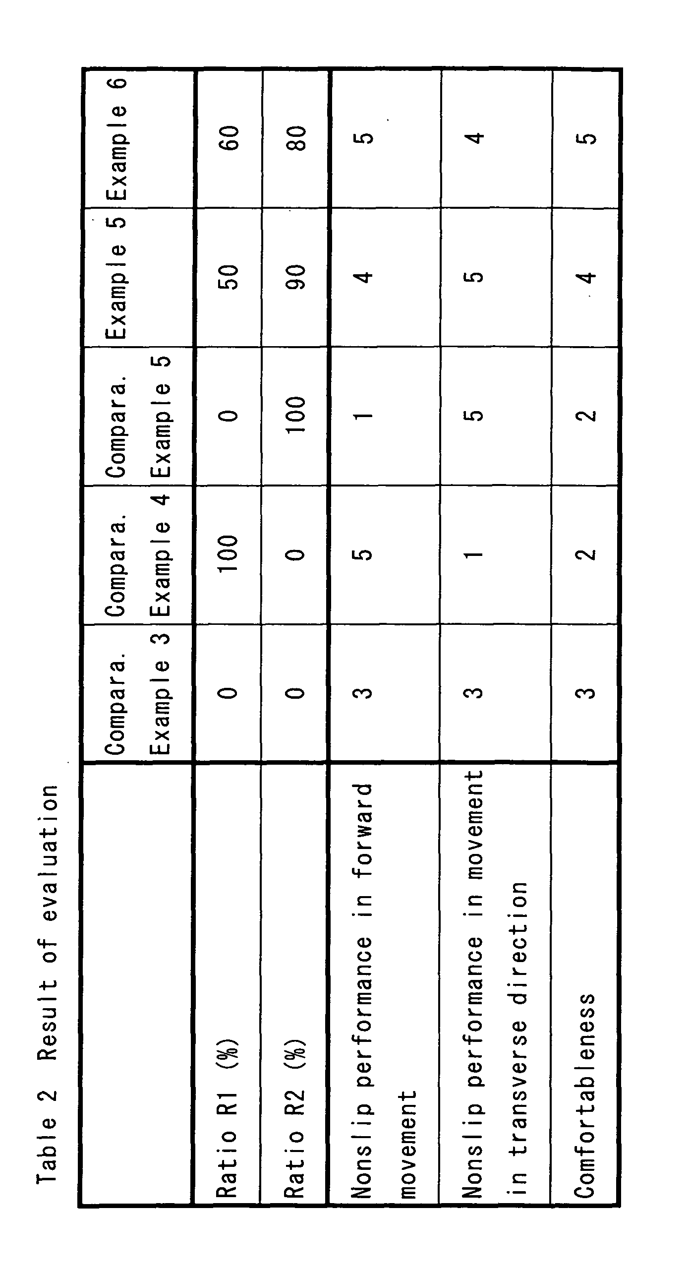
[Example 6 and Comparative Examples 4 and 5]
Tennis shoes according to an example 6 and comparative
examples 4 and 5 were obtained in the same manner as in the
example 5 except that the mold was changed and a sole having
a specification shown in the following Table 2 was formed.
[Comparative Example 3]
A trade name of "CT592" put on the market and sold from
New Balance Japan Co., Ltd. was prepared for a comparative
example 3.
[Test for Practical Use]
A player was caused to put on tennis shoes and to carry
out the rally of tennis at an artificial turf court having sand
(a trade name of "OMNICOURT" manufactured by SUMITOMO RUBBER
INDUSTRIES, INC.). Thus, a nonslip performance in a forward
movement, and a nonslip performance and comfortableness in a
movement in a transverse direction were evaluated in five stages
of "1" to "5". The highest evaluation was indicated as "5".
An average value of the evaluations for ten players is shown
in the following Table 2. As shown in the Table 2, an outsole
according to each of the examples has excellent evaluation
results for all items.
Tennis shoes according to the present invention are
suitable for a play in various courts. The tennis shoes are
more suitable for a court having a small coefficient of friction
(an artificial turf court having sand and a clay court). In
particular, the tennis shoes are suitable for the artificial
turf court having sand. The tennis shoes can contribute to an
enhancement in the game result of a player.