EP1552645B1 - Data processing apparatus and method - Google Patents
Data processing apparatus and method Download PDFInfo
- Publication number
- EP1552645B1 EP1552645B1 EP03738242A EP03738242A EP1552645B1 EP 1552645 B1 EP1552645 B1 EP 1552645B1 EP 03738242 A EP03738242 A EP 03738242A EP 03738242 A EP03738242 A EP 03738242A EP 1552645 B1 EP1552645 B1 EP 1552645B1
- Authority
- EP
- European Patent Office
- Prior art keywords
- data
- error correction
- analogue
- digits
- representative
- Prior art date
- Legal status (The legal status is an assumption and is not a legal conclusion. Google has not performed a legal analysis and makes no representation as to the accuracy of the status listed.)
- Expired - Lifetime
Links
Images






Classifications
-
- H—ELECTRICITY
- H04—ELECTRIC COMMUNICATION TECHNIQUE
- H04L—TRANSMISSION OF DIGITAL INFORMATION, e.g. TELEGRAPHIC COMMUNICATION
- H04L1/00—Arrangements for detecting or preventing errors in the information received
- H04L1/004—Arrangements for detecting or preventing errors in the information received by using forward error control
- H04L1/0056—Systems characterized by the type of code used
- H04L1/0057—Block codes
-
- G—PHYSICS
- G06—COMPUTING OR CALCULATING; COUNTING
- G06V—IMAGE OR VIDEO RECOGNITION OR UNDERSTANDING
- G06V40/00—Recognition of biometric, human-related or animal-related patterns in image or video data
- G06V40/10—Human or animal bodies, e.g. vehicle occupants or pedestrians; Body parts, e.g. hands
- G06V40/18—Eye characteristics, e.g. of the iris
-
- G—PHYSICS
- G06—COMPUTING OR CALCULATING; COUNTING
- G06V—IMAGE OR VIDEO RECOGNITION OR UNDERSTANDING
- G06V40/00—Recognition of biometric, human-related or animal-related patterns in image or video data
- G06V40/10—Human or animal bodies, e.g. vehicle occupants or pedestrians; Body parts, e.g. hands
- G06V40/18—Eye characteristics, e.g. of the iris
- G06V40/193—Preprocessing; Feature extraction
-
- H—ELECTRICITY
- H04—ELECTRIC COMMUNICATION TECHNIQUE
- H04L—TRANSMISSION OF DIGITAL INFORMATION, e.g. TELEGRAPHIC COMMUNICATION
- H04L1/00—Arrangements for detecting or preventing errors in the information received
- H04L1/08—Arrangements for detecting or preventing errors in the information received by repeating transmission, e.g. Verdan system
Definitions
- This invention relates to the generation of a number representative of data from an analogue source.
- the invention has particular, but not exclusive, relevance to generating a number representative of an individual by processing biometric data obtained by measuring a distinctive characteristic of the individual.
- Every individual has a number of distinctive characteristics (e.g. fingerprints, iris patterns and retinal patterns) having attributes which can be measured to generate biometric data representative of the individual, and these distinctive characteristics form the basis of many identification systems.
- distinctive characteristics e.g. fingerprints, iris patterns and retinal patterns
- a reference set of biometric data is generated for an individual, and in a subsequent identification process a new set of biometric data is measured and compared with the reference set of biometric data.
- a positive identification is made if the new set of biometric data is sufficiently similar to, but not necessarily identical with, the reference set of biometric data.
- the reason why the newly measured set of biometric data need not be identical with the reference set of biometric data for a positive identification is that each time the same distinctive characteristic is measured, slightly different biometric data is generated due to the analogue nature (i.e. having values within a continuous range) of the measured attributes of the distinctive feature.
- US 6,363,485 discusses a biometric authenticator which generates a secret key using first partial seed data generated from received biometric data and second partial seed data retrieved from a memory within the biometric authenticator.
- the second partial seed data comprises an error correction code which allows for a certain number of errors in the first partial seed data to be corrected.
- the second partial seed data is accessed by the user inputting a personal identification number.
- US 6,219,794 discusses a method of reproducing a digital key using a biometric, such as a fingerprint.
- the digital key is linked to the biometric by a protective filter which in response to the input of a biometric generates a corresponding digital key.
- US 6,038,315 discusses a method of generating a password for a user in which during enrolment each user is associated with one of a set of secret codewords, and a reference value for the user is calculated by applying an XOR operation on biometric data for the user and the secret codeword.
- a new biometric reading for the user is taken to generate new biometric data for the user, and an XOR operation is performed on the new biometric data and the reference value for the user to generate an approximation of the secret codeword.
- the set of secret codewords are separated by Hamming distances which are sufficiently large that only one of the set will be close to the approximation of the secret codeword, and this one is used as the codeword.
- US 6,170,073 discusses a method of transmitting speech over a wireless communications system.
- a frame of speech is converted into a number of speech parameters, and these speech parameters are split into groups in accordance with their importance in making the speech intelligible.
- An error detection code is calculated for each group of speech parameters, and then the speech parameters and error detection codes are error correction encoded.
- An object of the present invention is to provide alternative schemes using error correction algorithms to enable a repeatable value to be derived from data obtained by measuring an analogue data source.
- an apparatus for generating a number representative of an analogue data source as claimed in claim 24 is provided.
- the lower significant bits are processed using an error correction technique having a higher power of error correction than a different error correction technique which is used for the higher significant bits. In this way, the amount of error correction data required can be minimised.
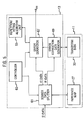
- Figure 1 schematically shows the main components of a system for generating a biometric number K bio from the iris pattern of an eye 1 of a human being.
- an iris scanner 3 records an image of the eye 1 and outputs corresponding image data to a data formatter 5, which configures the image data into a standard format.
- the data formatter 5 processes the image data using the image processing techniques described in US Patent No. 5,291,560 to form an iris code comprising four thousand and ninety-two bits arranged in a five hundred and twelve by eight array.
- a switch 7 directs the iris code generated by the data formatter 5 to a biometric number generator 9, which processes the iris code to generate a biometric number K bio and process data 11 which is stored for use in a subsequent biometric number regeneration operation.
- the biometric number generator 9 splits the iris code into two parts, uses the first part to generate the biometric number K bio and error correction data, and uses the second part to transform the error correction data to generate transform data which is stored as part of the process data 11.
- iris scanner 3 records a new image of the eye 1, and the data formatter 5 configures the resultant image data to produce a new iris code.
- the switch 7 directs the new iris code produced by the data formatter 5 to a biometric number regenerator 13 which, using the process data 11, regenerates the biometric K bio .
- biometric number generator 9 during enrolment and the biometric number regenerator 13 during the regeneration of the biometric number K bio will now be described in more detail.
- FIG. 2 shows the main components of the biometric number generator 9 and the process.data 11.
- the number generator 9 comprises a source data splitter 21 which splits the bit stream of data from the iris code, hereafter called S-data, into two bit streams in accordance with control signals from a controller 23.
- the source data splitter 21 outputs a first data bit stream conveying data, hereafter called K-data, for forming the biometric number, and a second data bit stream conveying data, hereafter called R-data, for use in the generation of the transform data.
- K-data first data bit stream conveying data
- R-data second data bit stream conveying data
- the relative proportions of S-data used for forming the K-data and the R-data are determined by the error correction algorithm applied by the biometric number generator 9.
- the error correction algorithm simply receives a single data bit of K-data, and outputs a corresponding codeword comprising the data bit followed by four check bits each having the same value as the received data bit. Therefore, if the error correction algorithm unit receives a data bit having a value "0", the error correction algorithm unit outputs the codeword "00000".
- This algorithm will hereafter be referred to as the repetition/voting algorithm, and is applied by a repetition/voting algorithm unit 25.
- any error correction algorithm receives a block of k bits of data, generates p check bits, and outputs a codeword having k+p bits. Therefore, for the repetition/voting algorithm used in this illustrative example, the k value is one and the p value is four.
- the controller interrogates the repetition/voting algorithm unit 25 to determine the k and p values, and sends a control signal to the source data splitter indicative of the determined k and p values.
- the source data splitter 21 also outputs reference map data 27, which forms part of the process data 11, indicating for each bit of the K-data and the R-data the location of the corresponding bit of S-data. In this way, during a subsequent number regeneration operation, it can be ensured that the same bits of S-data are used to form the K-data and the R-data as the enrolment process.
- the K-data bit stream is input to an error correction data generator 29, which is connected to the repetition/voting algorithm unit 25.
- the error correction data generator 29 sends each bit of K-data to the repetiaion/voting algorithm unit 25, extracts the check bits from the corresponding codewords returned by the repetition/voting algorithm unit 25, and outputs the extracted check bits as a stream of error correction data, hereafter called EC-data.
- the EC-data bit stream output by the error correction data generator 29 and the R-data bit stream output by the source data splitter 21 are input to a transform data generator 31, which applies a bitwise exclusive-OR operation to the EC-data bit stream and the R-data bit stream to generate transform data 33, which forms part of the process data 11.
- the corresponding EC-data bit stream is "111100000000”. If the corresponding sequence of R-data is "101110100100", then the resulting transform data is "010010100100". It will be appreciated that, without knowledge of the corresponding R-data sequence, the EC-data cannot be recovered from the transform data and therefore the stored transform data 11 gives no information about the K-data which forms the biometric value K bio .
- the source data splitter 21 includes a reference word generator 41 which receives the number N of data elements in the iris code (in this illustrative example four thousand and ninety-two) and the control signal from the controller 23 indicating a k value of one and a p value of 4. The reference word generator 41 then generates a reference data stream having N data elements, with each data element comprising a map code indicting the position of that data element within the reference data stream.
- the first data element of the reference data stream has a map code "0”
- the second data element has a map code "1”
- the third data element has a map code "2”
- so on until the final data element which has a map code "4091”.
- the reference word generator 41 then partitions the reference data stream into a sequence of words, each word formed by k+p consecutive data elements, and discards any data elements at the end of the data stream which are not contained in a full word. Therefore, as in this embodiment k+p equals five, the reference word generator 41 separates the four thousand and ninety-two data elements into a sequence of eight hundred and eighteen words, each including five consecutive data elements, and discards the remaining two data elements.
- the reference word generator 41 outputs the generated sequence of words to a data scrambler 43, which performs a pseudo-random scrambling of the data elements (i.e. a shuffling which appears random in nature but is in fact deterministic), and the shuffled data elements are output to a reference map generator 45, which forms a reference map indicating the position in the S-data of each bit of K-data and R-data.
- the reference map generator 45 receives the k and p values from the controller 23 in order to ensure that the correct amounts of S-data are apportioned to K-data and R-data.
- the source data splitter 21 also includes a data partitioner 47, which receives and caches the bit stream of S-data from the data formatter 5.
- the data partitioner 47 uses the reference map generated by the reference map generator 45 for the K-data and R-data bit streams.
- the data partitioner 47 looks up in the reference map data the location of the bit of the S-data bit stream which forms the first bit of the K-data, and outputs the value of the located bit, and so on for the second and subsequent bits of the K-data bit stream.
- the R-data bit stream is formed by the data partitioner 47 using the reference map data in an analogous way to the K-data bit stream. Therefore, in this illustrative example the data partitioner outputs a K-data bit stream comprising eight hundred and eighteen bits and a R-data bit stream comprising three thousand two hundred and seventy-two bits.
- the data formatter 5 stores the iris code in the form of a bit array having eight rows and five hundred and twelve columns. Although there is a high level of randomness to the values of the bit array, in this embodiment the data in each column, which corresponds to a radial direction of the iris, shows a level of order.
- the data formatter 5 outputs the iris code column by column, and therefore neighbouring bits of the S-data bit stream show some measure of correlation.
- the pseudo-random scrambling performed by the data scrambler 43 disperses the data elements in each column and therefore increases the randomness of the K-data and R-data bit streams.
- a further advantage of dispersing the data elements in each column is that if there is a localised group of errors in the iris code, then it is easier to correct the group of errors after dispersion.
- the data scrambler 43 performs two data scrambling operations. Firstly, the data scrambler 43 shuffles the words received by the reference word generator 41. The data scrambler 43 then forms an array by sequentially stacking the shuffled words. Therefore, in this illustrative example, the array is formed by eight hundred and eighteen rows each having five data elements. The data scrambler 43 then performs a rotational shifting operation of the data elements in each column. In this illustrative example, in the rotational shifting operation: the data elements of the first column remain in the same locations within the array; the data elements of the second column are shifted down the column one hundred and sixty-four places (i.e.
- the data elements of the third, fourth and fifth columns are shifted by three hundred and twenty-eight, four hundred and ninety-two and six hundred and fifty-six places respectively.
- the data scrambler 43 outputs the array formed by the shuffling operation to the reference map generator 45, which separates the first k columns (i.e. in this illustrative example the first column) to provide the locations of the data elements in the S-data bit stream to form the K-data bit stream, and then uses the remaining p columns to provide the locations of the data elements in the S-data bit stream to form the R-data bit stream.
- the reference map generator 45 separates the first k columns (i.e. in this illustrative example the first column) to provide the locations of the data elements in the S-data bit stream to form the K-data bit stream, and then uses the remaining p columns to provide the locations of the data elements in the S-data bit stream to form the R-data bit stream.
- the K-data bit stream is input to a data block generator 51, together with a control signal from the controller 23 indicating the value of the number k of data bits to be included in each block of data bits sent to the repetition/voting algorithm unit 25.
- the data block generator 51 partitions the K-data bit stream into a sequence of data blocks having k (i.e. in this embodiment one) bit, and outputs the sequence of data blocks to a data block transmitter 53, which sequentially transmits the data blocks to the repetition/votiwg algorithm unit 25.
- the repetition/voting algorithm unit 25 returns a codeword comprising the k data bits and p check bits.
- Each codeword is received by a codeword receiver 55, which forwards each received codeword to a check bits pass filter 57 which removes the k data bits and outputs the p check bits to form the EC-data bit stream.
- FIG. 5 schematically shows the main components of the biometric number regenerator 13.
- a S'-data bit stream output by the data formatter 5 during enrolment is input to a source data splitter 61, which splits the S'-data bit stream into a K'-data bit stream and a R'-data bit stream in accordance with a control signal from a controller 63 and using the reference map data 27 forming part of the process data 11 generated during enrolment.
- the control signal from the controller 63 conveys the values of k and p associated with a repetition/voting error correction algorithm unit 65 (i.e. a k value of one and a p value of four), which is connected to the controller 63.
- a repetition/voting error correction algorithm unit 65 i.e. a k value of one and a p value of four
- the K'-data bit stream and the R'-data bit stream are input to an error corrector 67 and an error correction data generator 69 respectively.
- the error correction data generator 69 applies a bitwise exclusive-OR operation to the R'-data bit stream and the transform data 33 generated during enrolment, to form an EC'-data bit stream, which is input to the error corrector 67.
- the error corrector 67 forms a sequence of codewords using the K'-data bit stream and the EC'-data bit stream and outputs each codeword to the repetition/voting algorithm unit 65. In this illustrative example, each codeword is formed by one bit from the K'-data bit stream followed by four bits from the EC'-data bit stream.
- the repetition/voting algorithm unit 65 For each received codeword, the repetition/voting algorithm unit 65 performs a voting operation to determine which bit value appears more often (hereafter called the majority bit value), converts all of the bits of the codeword to the determined majority bit value to form a converted codeword, and outputs the converted codeword.
- a voting operation to determine which bit value appears more often (hereafter called the majority bit value)
- converts all of the bits of the codeword to the determined majority bit value to form a converted codeword and outputs the converted codeword.
- the K-data bit stream has a sequence 100 and the corresponding sequence of the R-data bit stream is "101110100100", then the stored transform data is "010010100100".
- the generated K'-data and R'-data bit streams normally exhibit a number of differences from those generated during enrolment, and a typical example of corresponding bit sequences for the K'-bit stream and the R'-bit stream would be "101" and "100110001100” respectively.
- the error correction data generator 69 applies a bitwise exclusive-OR operation on the R'-data bit stream and the corresponding stored transform data to generate the EC'-data sequence "110100101000".
- the error corrector 67 combines each bit of the K'-data bit sequence with the corresponding four bits of the EC'-data bit stream to form the following three codewords: codeword 1 - 11101 codeword 2 - 00010 codeword 3 - 11000
- the codewords are then sequentially sent to the repetition/voting algorithm unit 65, which sets all the bits of each codeword to the majority bit value for the codeword, and returns the corrected codewords: corrected codeword 1 - 11111 corrected codeword 2 - 00000 corrected codeword 3 - 00000
- the error corrector 67 retrieves the data bits to form the corrected K'-data bit sequence "100", which is identical with the corresponding K-bit sequence generated during enrolment.
- Figure 6 shows the main components of the source data splitter 61.
- the control signal from the controller 63 indicating the values of k and p, which as described above are one and four respectively in this illustrative example, are input to a reference map generator 75 together with the reference map data 27.
- the reference map generator 75 generates a reference map indicating for each bit of the K'-data and R'-data bit streams the location of the corresponding bit of the S'-data bit stream.
- the S'-data bit stream is input to a data partitioner 77 which caches the S'-data bit stream, and then outputs the K'-data bit stream and the R'-data bit stream using the reference map provided by the reference map generator 75.
- the data partitioner 77 identifies and outputs the corresponding bit of the S'-data bit stream using the reference map.
- Figure 7 shows the main components of the error corrector 67.
- the K'-data bit stream is input to a data bits block generator 81 which groups the K'-data into blocks of k bits, the value of k being provided by a control signal from the controller 63.
- the EC'-data is input to a error correction bits block generator 83 which groups the EC'-data into blocks of p bits, with the value of p being provided by a control signal from the controller 63.
- the data bit blocks and the error correction bits blocks are sequentially input to a codeword generator 85, which concatenates each data bit block with the corresponding error correction bit block to form a codeword.
- the codeword generator 85 sequentially outputs the generated codewords to a codeword transmitter 87, which transmits each codeword to the repetition/voting algorithm unit 65.
- the corrected codewords produced by the repetition/voting algorithm unit 65 are received by a corrected codeword receiver 89 and forwarded to a data bits pass filter 91, which removes the check bits of the codeword and outputs the corrected data bits to form the biometric number K bio .
- the iris code from the data formatter 5 is split into two parts.
- the first part is used to generate a biometric number K bio and associated error correction data
- the second part is used to transform the error correction data to form transform data.
- biometric number regeneration the first part of the iris code is used to regenerate the biometric number, and the second part is used to revert the transform data back to error correction data.
- the error correction data is then used to correct errors in the regenerated biometric number.
- the generated biometric number K bio has eight hundred and eighteen bits. With this size of biometric number, there may still be a significant possibility of errors in one or more of the bits.
- a second illustrative example will now be described, with reference to Figures 8 and 9, in which two passes of error correction are performed to reduce the likelihood of error in the biometric number K bio .
- components which are identical to corresponding components of the first illustrative example have been referenced by the same numerals and will not be described in detail again.
- Figure 8 schematically shows the main components of a number generator 101 of the second illustrative example, which during enrolment receives S-data from a data formatter which is identical to the data formatter of the first embodiment.
- the S-data is input to a source data splitter 21, which is identical to the source data splitter 21 of the first illustrative example.
- the first pass of error correction uses a repetition/voting algorithm unit 25 which applies the same repetition/voting algorithm as described in the first illustrative example.
- a controller 103 interrogates the repetition/voting algorithm unit 25 to determine the associated k value and p value, and sends a control signal to the source data splitter 21 indicated the determined k and p values. Therefore, in this illustrative example the control signal received by the source data splitter 21 indicates that the value of k is one and the value of p is four.
- the source data splitter 21 outputs a K 1 -data stream and a R 1 -data stream, together with reference map data 27 which forms part of process data 105, in the same manner as described in the first illustrative example.
- the K 1 -data stream output by the source data splitter 21 is processed by the first error correction data generator 29a, using the repetition/voting algorithm unit 25, in the same manner as described in the first illustrative example to generate an EC 1 -data stream.
- the R 1 -data stream and the EC 1 -data stream are then input into a first transform data generator 31a, which performs an exclusive-OR operation to generate a first set of transform data 33 which is stored as part of the process data 105.
- the eight hundred and eighteen bits of K 1 -data form intermediate source data which is processed in a similar manner to the S-data to generate the biometric number K bio and a second set of transform data 105.
- a Golay (23,12) error correction algorithm which is a conventional error correction algorithm used for FEC encoding in digital data communications is used during the processing of the K 1 -data.
- the Golay (23,12) error correction algorithm a block of twelve data bits are processed to generate a block of eleven check bits, and the data bits and check bits are then combined to form a twenty-three bit codeword. Therefore, for the Golay (23,12) algorithm the value of k is twelve and the value of p is eleven.
- the Golay (23,12) error correction algorithm is applied by a Golay (23,12) algorithm unit 109, and the controller interrogates the Golay (23,12) algorithm unit 109 to determined the k value of twelve and the p value of eleven.
- the K 1 -data bit stream is input to a data splitter 107 together with a control signal from the controller 103 indicating the determined k and p values for the Golay (23,12) algorithm unit.
- the data splitter 107 partitions the K 1 -data bit stream into blocks of twenty-three bits, and for each block outputs the first twelve bits as a sequence of a K 2 -data bit stream and the remaining eleven bits as a sequence of a R 2 -data bit stream.
- the eight hundred and eighteen bits of K 1 -data form a four hundred and twenty bit sequence of K 2 -data, which forms the biometric number K bio , and a three hundred and eighty-five bit sequence of R 2 -data.
- the final eighteen bits of K 1 -data are discarded.
- the K 2 -data bit stream is input to a second error correction data generator 29b, together with a third control signal from the controller 103 conveying a k value of eleven and a p value of twelve.
- the second error correction data generator 29b is functionally identical to the error correction data generator of the first illustrative example.
- the second error correction data generator 29b partitions the K 2 -data bit stream into blocks of twelve data bits and sends each block to the Golay (23,12) algorithm unit 109, which applies the Golay (23,12) algorithm to generate a twenty-three bit codeword comprising the twelve data bits and eleven check bits.
- the Golay (23,12) algorithm unit 109 outputs each codeword to the second error correction data generator 29b, which extracts the check bits from each codeword and outputs the extracted check bits as an EC 2 -data bit stream.
- the EC 2 -data stream is input, together with the R 2 -data bit stream, to a second transform generator 31b which applies a bitwise exclusive-OR operation to the EC 2 -data bit stream and the R 2 -bit stream to form second transform data 111, which is stored as part of the process data 105.
- FIG. 9 schematically shows the main components of the number regenerator 121 of this illustrative example.
- the S'-data from the data formatter 5 is input to a source data splitter 61, which is identical to the source data splitter of the number regenerator of the first embodiment.
- a controller 123 interrogates a repetition/voting algorithm unit 65 to determine the associated k and p values, and outputs a control signal to the data splitter 61 indicating a k value of one and a p value of 4.
- the source data splitter 61 converts the S'-data into a K 1 '-data bit stream and a R 1 '-data bit stream in accordance with the control signal from the controller 123, using the reference map 27 in the process data 105 generated during enrolment.
- the R 1 '-data bit stream is input, together with the first set of transform data 33 of the process data 105 generated during enrolment, to a first error correction data generator 69a, which applies a bitwise exclusive-OR operation to generate an EC 1 '-data bit stream.
- the K 1 '-data and the EC 1 '-data bit streams are input to an error corrector 67a which, in the same manner as in the first illustrative example, outputs a corrected K 1 '-data bit stream using the repetition/voting algorithm unit 65, which applies the same repetition/voting error correction algorithm as the first illustrative example.
- the eight hundred and eighteen bits of the corrected K 1 '-data bit stream forms intermediate source data which is processed using a Golay (23,12) algorithm unit 127.
- the controller 123 interrogates the Golay (23,12) algorithm unit 127 and determines the associated k value of twelve and p value of eleven.
- the K 1 '-data bit stream is input to a data splitter 125 together with a control signal from the controller 123 indicating a k value of twelve and a p value of eleven.
- the data splitter 125 partitions the K 1 '-data into a sequence of thirty five blocks of twenty-three bits, sequentially outputs the first twelve bits of each block as a K 2 '-data bit stream, and sequentially outputs the remaining eleven bits of each block as a R 2 '-data bit stream.
- the R 2 '-data bit stream is input to a second error correction data generator 69b, together with the second set of transform data 111 stored in the process data 105 during enrolment.
- the second error correction data generator 69b applies a bitwise exclusive-OR operation to the R 2 '-data bit stream and the second set of transform data 111 to form an EC 2 '-data bit stream, which is input to a second error corrector 67b together with the K 2 '-data bit stream.
- the second error corrector 67b is functionally identical to the first error corrector 67a, and receives a control signal from the controller 123 indicating a k value of twelve and a p value of eleven. Accordingly, the second error corrector 67b partitions the K 2 '-data into blocks of twelve bits and the EC 2 '-data into blocks of eleven bits, and combines each block of K 2 '-data with a corresponding block of EC 2 '-data to form a codeword.
- the second error corrector 67b then sequentially transmits the codewords to the Golay (23,12) algorithm unit 127, which applies the Golay (23,12) error correction algorithm on each received codeword to generate a corrected codeword which is transmitted back to the error corrector 67b. As each corrected codeword is received, the second error corrector 67b extracts the data bits and outputs the extracted data bits to form the biometric number K bio .
- a second pass of error correction is applied to improve the repeatability of the biometric number K bio , at the expense of reducing the number of bits of the biometric number K bio because a larger proportion of the original S-data is effectively used to provide transform data for encoding the error correction data.
- an iris code is formed by the data formatter 5 having four thousand and ninety-two data elements, with each data element comprising a single bit.
- An alternative type data formatter is described in International Patent Application WO 02/098053.
- WO 02/098053 describes a feature template generator which extracts plural features from an image of an iris, with each feature having one or more attributes, and an attribute value stabiliser which uses data stored during enrolment to stabilise the respective values of the attributes.
- the resultant feature template is a forty-five by eighteen array of data elements, with each data element having a multi-bit value.
- FIG. 10 to 12 A first embodiment will now be described, with reference to Figures 10 to 12, in which the image data of the eye of an individual is configured by a data formatter as described in WO 02/098053 to produce a forty-five by eighteen array of data elements, with each data element having a multi-bit value.
- FIG. 10 to 12 components which are identical to corresponding components of the first illustrative example have been referenced by the same reference numerals and will not be described in detail again.
- the lower significant bits and the higher significant bits are processed using different error correction algorithms with the aim of reducing the amount of error correction data required to achieve a desired level of repeatability.
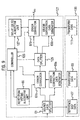
- Figure 10 schematically illustrates the main components of a number generator 141 which in this embodiment processes the data array produced by the data formatter to generate a biometric number K bio and process data 143 for use in a subsequent number regeneration operation.
- the data from the data formatter is input to a data element splitter 145, which for each data element directs the least significant bit of the associated value to a LSB data array 147 and directs the next least significant bit of the associated value to a HSB data array 149. In this embodiment, any bits of the value of a data element above the second least significant bit are discarded.
- Both of the LSB data array 147 and the HSB data array 149 are therefore in the format of a forty-five by eighteen array of data elements with each data element comprising a single data bit.
- error correction data for the LSB data array 147 and the HSB data array 149 are processed separately using different error correction algorithms.
- the LSB data array 147 is processed using the repetition/voting error correction algorithm
- the HSB data array is processed using the Golay (23,12) error correction algorithm.
- a first switch 151a is positioned with the LSB data array 147 and the HSB data array 149 on one side of the first switch 151a, and a source data splitter 21 which is identical to the source data splitter of the first illustrative example on the other side of the first switch 151a.
- a second switch 151b is positioned with an error correction data generator 29 on one side of the second switch 151b, and a repetition/voting error correction algorithm unit 25 and a Golay (23,12) error correction algorithm unit 109 on the other side of the second switch 151b,
- a controller 153 outputs control signals to set the first switch 151a so that the LSB data array 147 is connected to the source data splitter 21, and to set the second switch 151b so that the error correction data generator 29 is connected to the repetition/voting error correction algorithm unit 25.
- the controller 153 also extracts the k value of one and the p value of four from the repetition/voting algorithm unit 25, and sends corresponding control signals to the source data splitter 21 and the error correction data generator 29.
- the source data splitter 21 separates the eight hundred and ten data bits from the LSB-data array 147 into one hundred and sixty-two K L -data bits and six hundred and forty-eight R L -data bits in accordance with a generated LSB reference map, and stores LSB reference map data 155a as part of the process data 143.
- the K L -data bit stream is output to form part of the biometric number K bio , and is also input to the error correction data generator 29 which generates an EC L -data bit stream using the repetition/voting algorithm unit 25 as described in the first embodiment.
- the EC L -data bit stream is input, together with the R L -data bit stream, to a transform data generator 31 which performs a bitwise exclusive-OR operation to generate six hundred and forty eight bits of LSB transform data 157a which are stored as part of the process data 147.
- the controller 153 switches the first switch 151a and the second switch 151b so that the HSB data array 149 is connected to the source data splitter 21 and the error correction data generator 29 is connected to the Golay (23,12) algorithm unit 109.
- the controller 153 also extracts the k value of twelve and the p value of eleven from the Golay (23,12) algorithm unit, and sends corresponding control signals to the source data splitter 21 and the error correction data generator 29.
- the source data splitter 21 separates the eight hundred and ten data bits from the HSB-data array 149 into four hundred and twenty K H -data bits and three hundred and eighty-five R H -data bits (the remaining five data bits being discarded) according to a generated HSB reference map, and stores HSB reference map data 155b as part of the process data 143.
- the K H -data bit stream is output to form the remainder of the biometric number K bio , and is also input to the error correction data generator 29, which generates an EC H -data bit stream using the Golay (23,12) algorithm unit 109.
- the error correction data generator 29 outputs an EC H -data bit stream which is input, together with the R H -data bit stream, to the transform data generator 31, which performs a bitwise exclusive-OR operation to generate three hundred and eighty-five bits of HSB transform data 157b which are stored as part of the process data 143.
- the proportion of the data bits of the HSB data array 149 used to generate transform data is less than for the LSB data array 147.
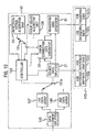
- Figure 11 schematically shows the main components of a number regenerator 161 which is used to regenerate the biometric number K bio , using the process data 143 generated during enrolment, from a data array produced by the data formatter from a scan of the eye of the individual.
- a data element separator 145 which directs the lowest significant bit of each data element to a LSB data array 147, directs the next lowest significant bit to a HSB data array 149, and discards any remaining bits.
- a first switch 163a is positioned with the LSB data array 147 and the HSB data array 149 on one side, and a source data splitter 61 (which is identical to the source data splitter of the number regenerator of the first illustrative example) on the other side.
- a second switch 163b is positioned with an error corrector 165 on one side, and a repetition/voting error correction algorithm unit 65 and a Golay (23,12) error correction algorithm unit 127 on the other side.
- a controller 167 outputs control signals to set the first switch 163a so that the LSB data array 147 is connected to the source data splitter 21, and to set the second switch 163b so that the error corrector 29 is connected to the repetition/voting error correction algorithm unit 25.
- the controller 153 also extracts a k value of one and the p value of four from the repetition/voting algorithm unit 25, and sends corresponding control signals to the source data splitter 21 and the error corrector 165.
- the source data splitter 61 separates the eight hundred and ten data bits from the LSB-data array 147 into one hundred and sixty-two K L '-data bits and six hundred and forty-eight R L '-data bits in accordance with the LSB reference map data 155a stored in the process data 143.
- the K L '-data bit stream and the R 1 '-data bit stream are input to the error corrector 165 and an error correction data generator 69 respectively.
- the error correction data generator 69 applies a bitwise exclusive-OR operation to the R L '-data bit stream and the LSB transform data 157a from the process data 143 generated during enrolment to generate an EC L '-data bit stream which is input to the error corrector 165.
- the error corrector 165 forms a sequence of codewords using the K L '-data bit stream and the EC L '-data bit stream and outputs corresponding codewords to the repetition/voting algorithm unit 65.
- each codeword is formed by one bit from the K L '-data bit stream followed by four bits from the EC L '-data bit stream.
- the repetition/voting algorithm unit 65 For each received codeword, the repetition/voting algorithm unit 65 generates and outputs a corrected codeword.
- the error corrector 165 sequentially receives the corrected codewords, removes the check bits, and outputs the remaining data bits to form part of the biometric number K bio .
- the error corrector 165 also compares each original codeword output to the repetition/voting algorithm unit 65 with the returned corrected codeword, and identifies which data bits have been changed. This information is subsequently used in the processing of the HSB data array 149.
- the controller 167 After all the data bits of the LSB data array 147 have been processed, the controller 167 outputs control signals setting the first switch 163a to connect the HSB data array 149 and the source data splitter 21 and the second switch 163b to connect the error corrector 165 and the Golay (23,12) algorithm unit 127.
- the controller 163 also interrogates the Golay (23,12) algorithm unit 127 to recover the k value of eleven and the p value of twelve, and sends corresponding control signals to the source data splitter 61 and the error corrector 165.
- the source data splitter 61 separates the eight hundred and ten data bits from the HSB-data array 147 into four hundred and twenty K H '-data bits and three hundred and eighty-five R H '-data bits in accordance with the HSB reference map data 155b stored in the process data 143.
- the K H '-data bit stream and the R H '-data bit stream are input to the error corrector 165 and the error correction data generator 69 respectively.
- the error correction data generator 69 applies a bitwise exclusive-OR operation to the R H '-data bit stream and the HSB transform data 157b from the process data 143 generated during enrolment to generate an EC H '-data bit stream which is input to the error corrector 165.
- the error corrector 165 forms a sequence of codewords using the K H '-data bit stream and the EC H '-data bit stream and outputs corresponding codewords to the Golay (23,12) algorithm unit 127.
- each codeword is formed by twelve bits from the K H '-data bit stream followed by eleven bits from the EC H '-data bit stream.
- the Golay (23,12) algorithm unit 127 For each received codeword, the Golay (23,12) algorithm unit 127 generates and outputs a corrected codeword.
- the error corrector 165 receives the corrected codewords, and uses the corrected codewords to form the remaining bits of the biometric number K bio .
- the error corrector 165 includes a suspect data elements identifier 171 which during the processing of the LSB data array 147 identifies the data bits whose values are corrected by the repetition/voting algorithm unit 25. If the lowest significant bit of a data element is incorrect, then there is a higher likelihood that the next lowest significant bit of that data element is also incorrect. The knowledge of the position of these suspect data elements is used during the processing of the HSB data array 149. This allows a reduced amount of error correction data to be generated and stored during enrolment, and consequently allows the biometric number K bio to have an increased number of bits.
- the K L '-data bit stream is input to a data bits block generator 173 which, in accordance with a control signal from the controller 167 indicating a k value of one, outputs the K L '-data in blocks of one data bit to a codeword generator 85.
- the EC L '-data is input to a check bits block generator 175 which, in accordance with a control signal from the controller 167 indicating a p value of four, outputs the R L '-data to the codeword generator 85 in blocks of four check bits.
- the codeword generator 85 forms a codeword by concatenating each data bit with the corresponding block of four check bits, and outputs the generated codeword to a codeword transmitter 87 and to the suspect data elements identifier 171.
- the codeword transmitter 87 outputs each generated codeword to the repetition/voting algorithm unit 65, and a corrected codeword receiver 89 receives a returned corrected codeword.
- Each received corrected codeword is input to the suspect data elements identifier 171 and to a codeword selector 177, which during processing of the LSB data array 147 simply transmits each corrected codeword to a data bits pass filter 91 which removes the check bits and outputs the remaining data bits to form part of the biometric number K bio .
- each codeword is compared to the corresponding corrected codeword by the suspect data elements identifier 171 to identify which bits have been corrected. For each corrected bit identified, the suspect data elements identifier 171 identifies the corresponding data element of the LSB data array 147 using the LSB reference map data 155a, then identifies the location of the bit of the K H '-data or EC H '-data which corresponds to the identified data element using the HSB reference map data 155b, and then tags that data bit location as a suspect data bit.
- the K H '-data bit stream is input to a data bits block generator 173 which, in accordance with a control signal from the controller 167 indicating a k value of twelve, partitions the K H '-data into blocks of twelve data bits.
- the EC H '-data bit stream is input to a check bits block generator 175 which, in accordance with a control signal from the controller 167 indicating a p value of eleven, partitions the EC H '-data into blocks of eleven bits.
- the suspect data elements identifier 171 determines the total number S of suspect bits. The suspect data elements identifier 171 then controls the data bits block generator 173 and the check bits block generator 175 to output data bit blocks and check bit blocks so that the codeword generator 85 outputs test codewords with every possible combination of values of the suspect bits, so that the codeword generator 85 generates 2 s different test codewords.
- the generated test codewords are input to the codeword transmitter 87, and the 2 s corrected test codewords received from the Golay (23,12) algorithm unit 109 are input to the codeword selector 177, which compares the 2 s corrected codewords and outputs the codeword which appears most frequently to the data bits pass filter 91 which removes the check bits and outputs the remaining data bits to form part of the biometric number K bio .
- a data bits block and a check bits block contain between them three suspect bits, then eight (i.e. 2 s ) test codewords are generated, with the values of the suspect bits in the eight test codewords being assigned the values 0-0-0, 0-0-1, 0-1-0, 0-1-1, 1-0-0, 1-0-1, 1-1-0 and 1-1-1 respectively.
- the Golay (23,12) algorithm is able to correct three incorrect data bits and therefore, if the only differences between the test codewords and the corresponding original codeword generated during enrolment are in the suspect data bits, the Golay (23,12) algorithm unit 109 corrects all the differences and returns eight identical corrected code words.
- the codeword selector 177 identifies the value of the four identical codewords, and outputs the identified value.
- the suspect data elements identifier during number regeneration the suspect data elements identifier generates a fault map identifying data elements of the source data which contain errors in the lowest significant bit.
- This fault map is used in the first embodiment during the processing of higher significant bits of the suspect data elements in order to allow a reduced amount of error correction data to be used.
- Such a fault map could be used in a number of other ways to improve the reliability of number regeneration.
- the fault map indicates a cluster of errors associated with a common portion of the iris, then this may indicate that the recorded image of that portion of the iris is unsound, for example due to reflected light or by being obscured by eyelids or eyelashes.
- the suspect data elements identifier tags all the data elements associated with the corresponding portion of the iris, even those whose values were not corrected, suspect.
- the number regenerator then re-processes the lowest significant bit data, and in the same manner as the first embodiment process the suspect data bits by creating multiple test codewords containing all possible combinations of values of the suspect bits, applying the error correction algorithm to all the test codewords, and selecting from the resulting corrected codewords the value which appears most frequently. In this way, the amount of error correction data needed to process the LSB data is reduced. It will be appreciated that such an arrangement may be applied to systems in which the data formatter configures the image data into data elements each having a single data bit, as in the first and second illustrative examples.
- the number regenerator outputs a signal requesting that the eye is imaged again to generate new S-data.
- the eye is imaged to provide replacement image data for just the suspect image portions, as the other image portions have already been judged sound.
- the faults identified in the fault map could arise from a number of sources. As described above, the faults could be caused by a region of the iris being obscured during an image capture. Alternatively the faults could be caused by random measurement error. In both of these cases, the location of the faults on the fault map should vary in a random manner. Another source for the faults in the fault map is systemic error, and such faults are characterised by appearing in the same place within the fault map with high regularity.
- fault maps for a plurality of number regeneration operations are stored and compared to identify regularly occurring faults indicating systemic error.
- the fault maps are stored in an encrypted format.
- the biometric number K bio is used as the cryptographic key of a symmetric encryption algorithm which is used to encrypt the fault maps.
- data elements within the source data which are affected by systemic error are identified from the fault maps, and are labelled as suspect. The processing of the suspect data elements is then performed as described above.
- additional transform data is used to transform the data elements exhibiting systemic error back to their enrolment values.
- a new enrolment process is performed.
- the S-data comprises a plurality of data elements with each data element having a multi-bit value.
- the lowest significant bits of the data elements are initially processed, and suspect data elements identified. In this way, the error correction of the higher significant bit can be made more efficient.
- the same technique can be applied to data which is not in binary format.
- the same technique can be applied to data which is not in binary format.
- other combinations of significant bits of the data element could be processed. For example, if each data element has a four bit value, of which the least significant bit is found to vary randomly between captures of source data, then the least significant bit can be discarded and the biometric number generated using the second and third least significant bits.
- the lowest significant bits are first processed and a first fault map generated, the second least significant bits are then processed using the first fault map and a second fault map generated indicating errors in the second significant bits, the third significant bits are then processed using the second fault map and a third fault map generated indicating errors in the third significant bit, and so on to the most significant bit which is processed.
- the first pass of error correction is performed using a repetition/voting algorithm.
- This is generally preferred because the repetition/voting algorithm allows correction of a comparatively large number of errors, albeit at the expense of requiring a large amount of error correction data.
- a feature of the repetition/voting algorithm used is that each codeword includes a single data bit. This allows the K 1 -data from the first pass of error correction to be separated into K 2 -data and R 2 -data without any data shuffling, because typically any errors in the K 1 -data are randomly distributed.
- a feature that is common to most error correction algorithms is that if the codeword contains more errors than the algorithm can correct, then the codeword generated by applying the algorithm includes at least as many errors as the original codeword. For example, if four errors are present in a twenty-three bit codeword for the Golay (23,12) algorithm, then the resultant codeword contains more than four errors. Such a concentration of errors is unlikely to be correctable in a second pass of error correction.
- the Golay (23,12) algorithm is used to perform the first pass of error correction
- the BCH (32,21) algorithm is used for the second pass of error correction.
- the data splitter 107 of the number generator is replaced by a data splitter functionally identical to the source data splitter of the number generator of the first illustrative example.
- the source data splitter shuffles the data bits of the K 1 -data bit stream and stores corresponding reference map data.
- the data splitter of the number regenerator is replaced by a source data splitter which is functionally identical to the source data splitter of the number regenerator of the first illustrative example.
- the source data splitter uses the stored reference map data to shuffle the data bits of the K 1 '-data bit stream in the same manner as the data bits of the K 1 -data bit stream were shuffled during enrolment. In this way, errors in the K 1 -data bit stream are dispersed.
- the K 1 -data effectively forms a first biometric number representative of the iris and the K 2 -data forms a second biometric number representative of the iris, with the second biometric number having a higher repeatability but less binary digits.
- the K 2 -data is split into K 3 -data and R 3 -data, the K 3 -data being used to form a third biometric number representative of the iris and the R 3 -data being used to form redundant data for mapping error correction data corresponding to the third biometric number. In this way, three passes of error correction are performed. It will be appreciated that the only limit to the number of error correction passes performed is the amount of the original source data, as with each pass of error correction the resulting biometric number will have less binary digits.
- the multiple pass error correction technique of the second illustrative example could also be applied to the multi-bit processing of the first embodiment.
- the biometric number generated from the LSB-data and/or the HSB-data could be split into new K-data and R-data for another pass of error correction.
- the same error correction algorithm could be used for each pass of error correction, or alternatively different error correction algorithms could be used for different passes of error correction.
- a transform data generator applies a bitwise exclusive-OR operation to a stream of error correction data and a stream of redundant data (i.e, the R-data) to generate transform data
- an error correction data generator applies to bitwise exclusive-OR operation to a stream of redundant data (i.e. the R'-data) and the stored transform data to recover the error correction data.
- Alternative mapping operations could be performed to map between the error correction data and the transform data using redundant data without the transform data providing information on the biometric number K bio . For example, a simple addition operation could be performed on the error correction data and the redundant data during enrolment, and a simple subtraction operation performed on the transform data and the redundant data during number regeneration. Such mapping operations are generically termed binomial mapping operations.
- the redundant data and the error correction data is formed by a random distribution of approximately equal numbers of bits having a value "1" and bits having a value "0", in which case the randomness of the redundant data and error correction data is optimal. In some occasions, however, this may not be the case. For example, if the highest significant bit of a data element having multiple significant bits is processed, then it is possible that the majority of the redundant data will have a value "0". If this coincides with error correction data which predominantly has the value "0", then to improve security of the K-data and R-data the transform data may be generated by storing a series of instructions indicating how bits of redundant data can be inverted and/or re-ordered to form the error correction data. In this way, it is more difficult to extract useful information about the R-data and the error correction data from the transform data.
- the multi-bit data element processing techniques described above could also be applied to a number generation system in which error correction data is directly stored (i.e. is not mapped into transform data).
- a repetition/voting error correction algorithm is applied in which four check bits are assigned to each data bit. It will be appreciated that an alternative number of check bits could be used, although it is preferred that an even number of check bits is used to prevent any ties in the voting operation during number regeneration (i.e. the same number of data bits having value "0" as having value "1").
- the number generators and the number regenerators have been designed so that the error correction algorithm used can be changed simply by replacing the existing error correction algorithm unit by the error correction algorithm unit for the new error correction algorithm.
- the controller determines the k value and the p value associated with the new error correction algorithm unit, and outputs control signals ensuring that the data splitters apportion the S-data into K-data and R-data correctly, that the error correction data generator outputs blocks of k data bits to the error correction algorithm unit during enrolment, and that the error corrector outputs codewords having k data bits and p check bits to the error correction algorithm unit during number regeneration.
- Examples of other error correction algorithms which could be used include the BCH (32,21) algorithm and the Hamming (8,4) algorithm.
- some of the source data is discarded because the amount of source data does not correspond to an integer number of codewords. It will be appreciated that this discarded data could be constructively used. For example, error detection data could be generated for the biometric number K bio , and the discarded source data used to map the error detection data into transform data.
- a source data splitter 61 during enrolment a source data splitter 61 generates a reference map indicating for the K-data and the R-data, the corresponding elements of the S-data.
- the reference map is stored and used by a source data splitter in a subsequent number regeneration operation.
- the source data splitter during enrolment could perform a predetermined shuffling operation, with the source data splitter being programmed to perform the same shuffling operation during number regeneration. In this way, there is no requirement to store the reference map.
- a reference map can be transiently formed during number regeneration to enable the suspect data elements to be tracked back to the original S-data locations.
- the source data is formed by imaging the iris of a human being.
- the source data could be formed by measuring other distinctive characteristics of an individual.
- the source data could be formed by imaging a fingerprint or a retina of the individual.
- the source data could be formed by recording a sequence of utterances by the individual. Details of techniques for formatting biometric data from fingerprints and retina patterns can be found in International Patent Application WO 02/098053.
- the source data could be formed from a number of source data pools relating to the same distinctive feature.
- the S-data could be formed by the combination of formatted data provided by the iris image data processing techniques described in US Patent No. 5,291,560 and WO 02/098053.
- the S-data could be formed from a number of source data pools representing different distinctive characteristics (e.g. iris pattern and fingerprint) of an individual.
- the data associated with this region could be separated off to form a separate source data pool.
- each source data pool will have an associated error behaviour. For example, one source data pool may have an expected error rate of one bit in ten while another source data pool may have an expected error rate of one bit in six.
- a plurality of source data pools are processed by respective error correction algorithms, which generally will not be the same, to produce respective intermediate source data pools all having a substantially constant error performance. The intermediate source data pools are then combined, and an additional pass of error correction applied to the combined intermediate source data pool.
- error correction algorithms can be used, in one or more passes of error correction, to process analogue data representative of an analogue data source to generate a number representative of the analogue data source.
- the choice of error correction methodology is determined by predicting for a set of analogue data the fault rate for all possible error correction methodologies, and identifying the error correction methodology which provides the largest number with a predicted fault rate within a desired tolerance level.
- the error correction performance of each error correction methodology may be determined from the likelihood of errors in the source analogue data and the error correcting performance of the various error correction algorithms.
- biometric data from other animals could be used to generate a biometric number.
- some inanimate objects have distinctive features from which a physical value representative of the inanimate object can be derived.
- analogue data may be generated by imaging an engraving or a jewel with an image sensor.
- a purpose-defined object having sharply defined, but random, geometric properties can be probed using ultrasound to generate analogue data.
- the same apparatus is used both to carry out the enrolment process and the subsequent number regeneration
- the enrolment process and the number regeneration process could be performed by separate devices.
- the process data must be transferred from the enrolment apparatus to the number regeneration apparatus. This could be performed, for example, by transferring the process vector to a storage device (e.g. a floppy disc or a CD-ROM) which is moved to the number regeneration apparatus where the process vector is downloaded into the regeneration apparatus, or alternatively the enrolment apparatus and the number regeneration apparatus could be connected via a computer network, in which the process vector is transmitted across the computer network as an electrical signal.
- a storage device e.g. a floppy disc or a CD-ROM
- the processing of the analogue data can either be performed by a hardware device, software running on a computer, or the processing could be split between a hardware device and software running on a computer.
- the invention is well suited to being implemented in software using an object oriented programming language such as Java or C++.
- each error correction algorithm can be implemented by a respective different one of a library of program objects which can be selectively addressed by an error correction data generator and an error corrector.
- the invention also extends to computer programs, particularly computer programs on or in a carrier, adapted for putting the invention into practice.
- the computer program may be in the form of source code, object code, a code intermediate source and object code such as in partially compiled form, or in any other form suitable for use in the implementation of the processes according to the invention.
- the carrier may be any entity or device capable of carrying the program.
- the carrier may comprise a storage medium such as a ROM, for example a CD ROM or a semiconductor ROM, or a magnetic recording medium, for example a floppy disk or hard disk.
- the carrier may be a transmissible carrier such as an electrical or optical signal which may be conveyed via electrical or optical cable or by radio or other means.
- the carrier may be constituted by such cable or other device or means.
- the carrier may be an integrated circuit in which the program is embedded, the integrated circuit being adapted for performing, or for use in the performance of, the relevant processes.
Landscapes
- Engineering & Computer Science (AREA)
- Multimedia (AREA)
- General Physics & Mathematics (AREA)
- Theoretical Computer Science (AREA)
- Health & Medical Sciences (AREA)
- General Health & Medical Sciences (AREA)
- Ophthalmology & Optometry (AREA)
- Human Computer Interaction (AREA)
- Physics & Mathematics (AREA)
- Signal Processing (AREA)
- Computer Networks & Wireless Communication (AREA)
- Computer Vision & Pattern Recognition (AREA)
- Detection And Correction Of Errors (AREA)
- Error Detection And Correction (AREA)
- Measurement And Recording Of Electrical Phenomena And Electrical Characteristics Of The Living Body (AREA)
- Optical Communication System (AREA)
- Noodles (AREA)
- Hardware Redundancy (AREA)
- Image Processing (AREA)
- Collating Specific Patterns (AREA)
- Indication And Recording Devices For Special Purposes And Tariff Metering Devices (AREA)
Abstract
Description
- This invention relates to the generation of a number representative of data from an analogue source. The invention has particular, but not exclusive, relevance to generating a number representative of an individual by processing biometric data obtained by measuring a distinctive characteristic of the individual.
- Every individual has a number of distinctive characteristics (e.g. fingerprints, iris patterns and retinal patterns) having attributes which can be measured to generate biometric data representative of the individual, and these distinctive characteristics form the basis of many identification systems. Generally, during an enrolment process a reference set of biometric data is generated for an individual, and in a subsequent identification process a new set of biometric data is measured and compared with the reference set of biometric data. A positive identification is made if the new set of biometric data is sufficiently similar to, but not necessarily identical with, the reference set of biometric data. The reason why the newly measured set of biometric data need not be identical with the reference set of biometric data for a positive identification is that each time the same distinctive characteristic is measured, slightly different biometric data is generated due to the analogue nature (i.e. having values within a continuous range) of the measured attributes of the distinctive feature.
- A paper entitled "On the relation of error correction and cryptography to an offline biometric based identification scheme", WCC99, Workshop on Coding and cryptography January 1999,Paris, France, describes generating a biometric value which is exactly reproducible on a regular basis by employing error detection and correction techniques. In particular, this paper describes measuring the iris of an individual during enrolment to obtain an array of binary digits (bits), and applying conventional error correction algorithms, as are commonly used in forward error correction (FEC) encoding in digital data communication, to generate corresponding check bits. During a subsequent identification, the iris of the individual is re-measured to form a new array of data bits, and then the error correction algorithm corrects the new array of data bits using the check bits generated during enrolment. A disadvantage of this system is that the check bits generated during enrolment must be stored, and could therefore be used to aid fraudulent use of the biometric value for the individual.
- US 6,363,485 discusses a biometric authenticator which generates a secret key using first partial seed data generated from received biometric data and second partial seed data retrieved from a memory within the biometric authenticator. The second partial seed data comprises an error correction code which allows for a certain number of errors in the first partial seed data to be corrected. The second partial seed data is accessed by the user inputting a personal identification number.
- US 6,219,794 discusses a method of reproducing a digital key using a biometric, such as a fingerprint. The digital key is linked to the biometric by a protective filter which in response to the input of a biometric generates a corresponding digital key.
- US 6,038,315 discusses a method of generating a password for a user in which during enrolment each user is associated with one of a set of secret codewords, and a reference value for the user is calculated by applying an XOR operation on biometric data for the user and the secret codeword. During password recovery, a new biometric reading for the user is taken to generate new biometric data for the user, and an XOR operation is performed on the new biometric data and the reference value for the user to generate an approximation of the secret codeword. The set of secret codewords are separated by Hamming distances which are sufficiently large that only one of the set will be close to the approximation of the secret codeword, and this one is used as the codeword.
- US 6,170,073 discusses a method of transmitting speech over a wireless communications system. A frame of speech is converted into a number of speech parameters, and these speech parameters are split into groups in accordance with their importance in making the speech intelligible. An error detection code is calculated for each group of speech parameters, and then the speech parameters and error detection codes are error correction encoded.
- An object of the present invention is to provide alternative schemes using error correction algorithms to enable a repeatable value to be derived from data obtained by measuring an analogue data source.
- According to an aspect of the invention, there is provided a method of generating a number representative of an analogue data source together with error correction data for said number as claimed in
claim 1. - According to another aspect of the invention, there is provided a method of generating a number representative of an analogue data source as claimed in claim 7.
- According to a further aspect of the invention, there is provided an apparatus for generating a number representative of an analogue data source together with error correction data for said number as claimed in claim 18.
- According to another aspect of the invention, there is provided an apparatus for generating a number representative of an analogue data source as claimed in claim 24.
- As the likelihood of errors occurring in the higher significant bits of the data elements is less than in the lower significant bits, the lower significant bits are processed using an error correction technique having a higher power of error correction than a different error correction technique which is used for the higher significant bits. In this way, the amount of error correction data required can be minimised.
- Various embodiments of the invention will now be described with reference to the accompanying Figures in which:
- Figure 1 schematically shows the main components of a number generation system;
- Figure 2 schematically shows the main components of a number generator and process data forming part of the number generation system illustrated in Figure 1;
- Figure 3 schematically shows the main components of a source data splitter forming part of the number generator illustrated in Figure 2;
- Figure 4 schematically shows the main components of an error correction data generator forming part of the number generator illustrated in Figure 2;
- Figure 5 schematically shows the main components of a number regenerator forming part of the number generation system illustrated in Figure 1, together with the main components of the process data;
- Figure 6 schematically shows the main components of a source data splitter forming part of the number regenerator illustrated in Figure 5;
- Figure 7 schematically shows the main components of an error corrector forming part of the number regenerator system illustrated in Figure 5;
- Figure 8 shows the main components of a number generator which forms part of a first alternative number generation system;
- Figure 9 shows the main components of a number regenerator which forms part of the first alternative number generation system;
- Figure 10 shows the main components of a number generator which forms part of a number generation system according to the invention;
- Figure 11 shows the main components of a number regenerator which forms part of a number generation system according to the invention; and
- Figure 12 shows the main components of an error corrector forming part of the number regenerator illustrated in Figure 11.
- Figure 1 schematically shows the main components of a system for generating a biometric number Kbio from the iris pattern of an
eye 1 of a human being. As shown, an iris scanner 3 records an image of theeye 1 and outputs corresponding image data to a data formatter 5, which configures the image data into a standard format. In this illustrative example, the data formatter 5 processes the image data using the image processing techniques described in US Patent No. 5,291,560 to form an iris code comprising four thousand and ninety-two bits arranged in a five hundred and twelve by eight array. During enrolment, a switch 7 directs the iris code generated by the data formatter 5 to abiometric number generator 9, which processes the iris code to generate a biometric number Kbio andprocess data 11 which is stored for use in a subsequent biometric number regeneration operation. In particular, as will be described in more detail hereafter, thebiometric number generator 9 splits the iris code into two parts, uses the first part to generate the biometric number Kbio and error correction data, and uses the second part to transform the error correction data to generate transform data which is stored as part of theprocess data 11. - During a biometric number regeneration operation, iris scanner 3 records a new image of the
eye 1, and the data formatter 5 configures the resultant image data to produce a new iris code. The switch 7 directs the new iris code produced by the data formatter 5 to abiometric number regenerator 13 which, using theprocess data 11, regenerates the biometric Kbio. - The operation of the
biometric number generator 9 during enrolment and thebiometric number regenerator 13 during the regeneration of the biometric number Kbio will now be described in more detail. - Figure 2 shows the main components of the
biometric number generator 9 and theprocess.data 11. As shown, thenumber generator 9 comprises asource data splitter 21 which splits the bit stream of data from the iris code, hereafter called S-data, into two bit streams in accordance with control signals from acontroller 23. In particular, the source data splitter 21 outputs a first data bit stream conveying data, hereafter called K-data, for forming the biometric number, and a second data bit stream conveying data, hereafter called R-data, for use in the generation of the transform data. - The relative proportions of S-data used for forming the K-data and the R-data are determined by the error correction algorithm applied by the
biometric number generator 9. In this illustrative example, the error correction algorithm simply receives a single data bit of K-data, and outputs a corresponding codeword comprising the data bit followed by four check bits each having the same value as the received data bit. Therefore, if the error correction algorithm unit receives a data bit having a value "0", the error correction algorithm unit outputs the codeword "00000". This algorithm will hereafter be referred to as the repetition/voting algorithm, and is applied by a repetition/voting algorithm unit 25. - In general, any error correction algorithm receives a block of k bits of data, generates p check bits, and outputs a codeword having k+p bits. Therefore, for the repetition/voting algorithm used in this illustrative example, the k value is one and the p value is four.
- One bit of R-data is required for each check bit in order to generate transform data. Therefore, in this illustrative example only one-fifth of the S-data can be used to form K-data because the remaining four-fifths are required to form R-data. In order to ensure that the
source data splitter 21 splits the S-data into K-data and R-data in the correct proportions, the controller interrogates the repetition/voting algorithm unit 25 to determine the k and p values, and sends a control signal to the source data splitter indicative of the determined k and p values. - The
source data splitter 21 also outputsreference map data 27, which forms part of theprocess data 11, indicating for each bit of the K-data and the R-data the location of the corresponding bit of S-data. In this way, during a subsequent number regeneration operation, it can be ensured that the same bits of S-data are used to form the K-data and the R-data as the enrolment process. - As well as being output by the
number generator 9 to form the biometric number Kbio, the K-data bit stream is input to an errorcorrection data generator 29, which is connected to the repetition/voting algorithm unit 25. In this illustrative example, the errorcorrection data generator 29 sends each bit of K-data to the repetiaion/voting algorithm unit 25, extracts the check bits from the corresponding codewords returned by the repetition/voting algorithm unit 25, and outputs the extracted check bits as a stream of error correction data, hereafter called EC-data. The EC-data bit stream output by the errorcorrection data generator 29 and the R-data bit stream output by thesource data splitter 21 are input to atransform data generator 31, which applies a bitwise exclusive-OR operation to the EC-data bit stream and the R-data bit stream to generatetransform data 33, which forms part of theprocess data 11. - As an example, for a sequence "100" of K-data, the corresponding EC-data bit stream is "111100000000". If the corresponding sequence of R-data is "101110100100", then the resulting transform data is "010010100100". It will be appreciated that, without knowledge of the corresponding R-data sequence, the EC-data cannot be recovered from the transform data and therefore the stored
transform data 11 gives no information about the K-data which forms the biometric value Kbio. - The
source data splitter 21 will now be described in more detail with reference to Figure 3. As shown, thesource data splitter 21 includes areference word generator 41 which receives the number N of data elements in the iris code (in this illustrative example four thousand and ninety-two) and the control signal from thecontroller 23 indicating a k value of one and a p value of 4. Thereference word generator 41 then generates a reference data stream having N data elements, with each data element comprising a map code indicting the position of that data element within the reference data stream. In particular, in this illustrative example the first data element of the reference data stream has a map code "0", the second data element has a map code "1", the third data element has a map code "2", and so on until the final data element which has a map code "4091". - The
reference word generator 41 then partitions the reference data stream into a sequence of words, each word formed by k+p consecutive data elements, and discards any data elements at the end of the data stream which are not contained in a full word. Therefore, as in this embodiment k+p equals five, thereference word generator 41 separates the four thousand and ninety-two data elements into a sequence of eight hundred and eighteen words, each including five consecutive data elements, and discards the remaining two data elements. - The
reference word generator 41 outputs the generated sequence of words to adata scrambler 43, which performs a pseudo-random scrambling of the data elements (i.e. a shuffling which appears random in nature but is in fact deterministic), and the shuffled data elements are output to areference map generator 45, which forms a reference map indicating the position in the S-data of each bit of K-data and R-data. Thereference map generator 45 receives the k and p values from thecontroller 23 in order to ensure that the correct amounts of S-data are apportioned to K-data and R-data. - The
source data splitter 21 also includes adata partitioner 47, which receives and caches the bit stream of S-data from the data formatter 5. The data partitioner 47 then uses the reference map generated by thereference map generator 45 for the K-data and R-data bit streams. In particular, to form the K-data bit stream thedata partitioner 47 looks up in the reference map data the location of the bit of the S-data bit stream which forms the first bit of the K-data, and outputs the value of the located bit, and so on for the second and subsequent bits of the K-data bit stream. The R-data bit stream is formed by thedata partitioner 47 using the reference map data in an analogous way to the K-data bit stream. Therefore, in this illustrative example the data partitioner outputs a K-data bit stream comprising eight hundred and eighteen bits and a R-data bit stream comprising three thousand two hundred and seventy-two bits. - As stated previously, the data formatter 5 stores the iris code in the form of a bit array having eight rows and five hundred and twelve columns. Although there is a high level of randomness to the values of the bit array, in this embodiment the data in each column, which corresponds to a radial direction of the iris, shows a level of order. The data formatter 5 outputs the iris code column by column, and therefore neighbouring bits of the S-data bit stream show some measure of correlation. However, the pseudo-random scrambling performed by the
data scrambler 43 disperses the data elements in each column and therefore increases the randomness of the K-data and R-data bit streams. A further advantage of dispersing the data elements in each column is that if there is a localised group of errors in the iris code, then it is easier to correct the group of errors after dispersion. - In this illustrative example, the
data scrambler 43 performs two data scrambling operations. Firstly, thedata scrambler 43 shuffles the words received by thereference word generator 41. The data scrambler 43 then forms an array by sequentially stacking the shuffled words. Therefore, in this illustrative example, the array is formed by eight hundred and eighteen rows each having five data elements. The data scrambler 43 then performs a rotational shifting operation of the data elements in each column. In this illustrative example, in the rotational shifting operation: the data elements of the first column remain in the same locations within the array; the data elements of the second column are shifted down the column one hundred and sixty-four places (i.e. are shifted by approximately one fifth of the size of the column) so that the first data element in the column becomes the one hundred and sixty-fifth data element in the column, and the bottom one hundred and sixty-four data element are shifted to the top of the column; in the same manner, the data elements of the third, fourth and fifth columns are shifted by three hundred and twenty-eight, four hundred and ninety-two and six hundred and fifty-six places respectively. - The data scrambler 43 outputs the array formed by the shuffling operation to the
reference map generator 45, which separates the first k columns (i.e. in this illustrative example the first column) to provide the locations of the data elements in the S-data bit stream to form the K-data bit stream, and then uses the remaining p columns to provide the locations of the data elements in the S-data bit stream to form the R-data bit stream. - The error
correction data generator 29 will now be described in more detail with reference to Figure 4. As shown, the K-data bit stream is input to adata block generator 51, together with a control signal from thecontroller 23 indicating the value of the number k of data bits to be included in each block of data bits sent to the repetition/voting algorithm unit 25. Thedata block generator 51 partitions the K-data bit stream into a sequence of data blocks having k (i.e. in this embodiment one) bit, and outputs the sequence of data blocks to adata block transmitter 53, which sequentially transmits the data blocks to the repetition/votiwg algorithm unit 25. For each data block transmitted, the repetition/voting algorithm unit 25 returns a codeword comprising the k data bits and p check bits. Each codeword is received by acodeword receiver 55, which forwards each received codeword to a check bits passfilter 57 which removes the k data bits and outputs the p check bits to form the EC-data bit stream. - Figure 5 schematically shows the main components of the
biometric number regenerator 13. As described previously, during regeneration a new image is formed of theeye 1 and the corresponding image data processed by the data formatter 5 to form a new iris code. As shown, a S'-data bit stream output by the data formatter 5 during enrolment is input to asource data splitter 61, which splits the S'-data bit stream into a K'-data bit stream and a R'-data bit stream in accordance with a control signal from acontroller 63 and using thereference map data 27 forming part of theprocess data 11 generated during enrolment. The control signal from thecontroller 63 conveys the values of k and p associated with a repetition/voting error correction algorithm unit 65 (i.e. a k value of one and a p value of four), which is connected to thecontroller 63. - The K'-data bit stream and the R'-data bit stream are input to an
error corrector 67 and an errorcorrection data generator 69 respectively. The errorcorrection data generator 69 applies a bitwise exclusive-OR operation to the R'-data bit stream and thetransform data 33 generated during enrolment, to form an EC'-data bit stream, which is input to theerror corrector 67. Theerror corrector 67 forms a sequence of codewords using the K'-data bit stream and the EC'-data bit stream and outputs each codeword to the repetition/voting algorithm unit 65. In this illustrative example, each codeword is formed by one bit from the K'-data bit stream followed by four bits from the EC'-data bit stream. For each received codeword, the repetition/voting algorithm unit 65 performs a voting operation to determine which bit value appears more often (hereafter called the majority bit value), converts all of the bits of the codeword to the determined majority bit value to form a converted codeword, and outputs the converted codeword. - For example, as described above if during enrolment the K-data bit stream has a sequence 100 and the corresponding sequence of the R-data bit stream is "101110100100", then the stored transform data is "010010100100". In a subsequent regeneration operation, the generated K'-data and R'-data bit streams normally exhibit a number of differences from those generated during enrolment, and a typical example of corresponding bit sequences for the K'-bit stream and the R'-bit stream would be "101" and "100110001100" respectively. The error
correction data generator 69 applies a bitwise exclusive-OR operation on the R'-data bit stream and the corresponding stored transform data to generate the EC'-data sequence "110100101000". - The
error corrector 67 combines each bit of the K'-data bit sequence with the corresponding four bits of the EC'-data bit stream to form the following three codewords:codeword 1 - 11101 codeword 2 - 00010 codeword 3 - 11000 - The codewords are then sequentially sent to the repetition/
voting algorithm unit 65, which sets all the bits of each codeword to the majority bit value for the codeword, and returns the corrected codewords:corrected codeword 1 - 11111 corrected codeword 2 - 00000 corrected codeword 3 - 00000 - From the corrected codewords, the
error corrector 67 retrieves the data bits to form the corrected K'-data bit sequence "100", which is identical with the corresponding K-bit sequence generated during enrolment. - Figure 6 shows the main components of the
source data splitter 61. The control signal from thecontroller 63 indicating the values of k and p, which as described above are one and four respectively in this illustrative example, are input to areference map generator 75 together with thereference map data 27. Thereference map generator 75 generates a reference map indicating for each bit of the K'-data and R'-data bit streams the location of the corresponding bit of the S'-data bit stream. - The S'-data bit stream is input to a
data partitioner 77 which caches the S'-data bit stream, and then outputs the K'-data bit stream and the R'-data bit stream using the reference map provided by thereference map generator 75. In particular, for each bit of the K'-data and the R'-data bit streams, thedata partitioner 77 identifies and outputs the corresponding bit of the S'-data bit stream using the reference map. - Figure 7 shows the main components of the
error corrector 67. As shown the K'-data bit stream is input to a data bits blockgenerator 81 which groups the K'-data into blocks of k bits, the value of k being provided by a control signal from thecontroller 63. Similarly, the EC'-data is input to a error correction bits blockgenerator 83 which groups the EC'-data into blocks of p bits, with the value of p being provided by a control signal from thecontroller 63. The data bit blocks and the error correction bits blocks are sequentially input to acodeword generator 85, which concatenates each data bit block with the corresponding error correction bit block to form a codeword. - The
codeword generator 85 sequentially outputs the generated codewords to acodeword transmitter 87, which transmits each codeword to the repetition/voting algorithm unit 65. The corrected codewords produced by the repetition/voting algorithm unit 65 are received by a correctedcodeword receiver 89 and forwarded to a data bits passfilter 91, which removes the check bits of the codeword and outputs the corrected data bits to form the biometric number Kbio. - In the first illustrative example, the iris code from the data formatter 5 is split into two parts. During enrolment, the first part is used to generate a biometric number Kbio and associated error correction data, and the second part is used to transform the error correction data to form transform data. During biometric number regeneration, the first part of the iris code is used to regenerate the biometric number, and the second part is used to revert the transform data back to error correction data. The error correction data is then used to correct errors in the regenerated biometric number.
- The generated biometric number Kbio has eight hundred and eighteen bits. With this size of biometric number, there may still be a significant possibility of errors in one or more of the bits. A second illustrative example will now be described, with reference to Figures 8 and 9, in which two passes of error correction are performed to reduce the likelihood of error in the biometric number Kbio. In Figures 8 and 9, components which are identical to corresponding components of the first illustrative example have been referenced by the same numerals and will not be described in detail again.
- Figure 8 schematically shows the main components of a
number generator 101 of the second illustrative example, which during enrolment receives S-data from a data formatter which is identical to the data formatter of the first embodiment. The S-data is input to asource data splitter 21, which is identical to thesource data splitter 21 of the first illustrative example. In this illustrative example, the first pass of error correction uses a repetition/voting algorithm unit 25 which applies the same repetition/voting algorithm as described in the first illustrative example. Acontroller 103 interrogates the repetition/voting algorithm unit 25 to determine the associated k value and p value, and sends a control signal to thesource data splitter 21 indicated the determined k and p values. Therefore, in this illustrative example the control signal received by thesource data splitter 21 indicates that the value of k is one and the value of p is four. - The
source data splitter 21 outputs a K1-data stream and a R1-data stream, together withreference map data 27 which forms part ofprocess data 105, in the same manner as described in the first illustrative example. The K1-data stream output by thesource data splitter 21 is processed by the first errorcorrection data generator 29a, using the repetition/voting algorithm unit 25, in the same manner as described in the first illustrative example to generate an EC1-data stream. The R1-data stream and the EC1-data stream are then input into a firsttransform data generator 31a, which performs an exclusive-OR operation to generate a first set oftransform data 33 which is stored as part of theprocess data 105. - In this illustrative example, the eight hundred and eighteen bits of K1-data form intermediate source data which is processed in a similar manner to the S-data to generate the biometric number Kbio and a second set of
transform data 105. In this illustrative example, a Golay (23,12) error correction algorithm, which is a conventional error correction algorithm used for FEC encoding in digital data communications is used during the processing of the K1-data. For the Golay (23,12) error correction algorithm, a block of twelve data bits are processed to generate a block of eleven check bits, and the data bits and check bits are then combined to form a twenty-three bit codeword. Therefore, for the Golay (23,12) algorithm the value of k is twelve and the value of p is eleven. - The Golay (23,12) error correction algorithm is applied by a Golay (23,12)
algorithm unit 109, and the controller interrogates the Golay (23,12)algorithm unit 109 to determined the k value of twelve and the p value of eleven. As shown in Figure 8, the K1-data bit stream is input to adata splitter 107 together with a control signal from thecontroller 103 indicating the determined k and p values for the Golay (23,12) algorithm unit. Thedata splitter 107 partitions the K1-data bit stream into blocks of twenty-three bits, and for each block outputs the first twelve bits as a sequence of a K2-data bit stream and the remaining eleven bits as a sequence of a R2-data bit stream. In this way, the eight hundred and eighteen bits of K1-data form a four hundred and twenty bit sequence of K2-data, which forms the biometric number Kbio, and a three hundred and eighty-five bit sequence of R2-data. The final eighteen bits of K1-data are discarded. - The K2-data bit stream is input to a second error
correction data generator 29b, together with a third control signal from thecontroller 103 conveying a k value of eleven and a p value of twelve. The second errorcorrection data generator 29b is functionally identical to the error correction data generator of the first illustrative example. In particular, in accordance with the control signal from thecontroller 103, the second errorcorrection data generator 29b partitions the K2-data bit stream into blocks of twelve data bits and sends each block to the Golay (23,12)algorithm unit 109, which applies the Golay (23,12) algorithm to generate a twenty-three bit codeword comprising the twelve data bits and eleven check bits. The Golay (23,12)algorithm unit 109 outputs each codeword to the second errorcorrection data generator 29b, which extracts the check bits from each codeword and outputs the extracted check bits as an EC2-data bit stream. - The EC2-data stream is input, together with the R2-data bit stream, to a
second transform generator 31b which applies a bitwise exclusive-OR operation to the EC2-data bit stream and the R2-bit stream to formsecond transform data 111, which is stored as part of theprocess data 105. - Figure 9 schematically shows the main components of the
number regenerator 121 of this illustrative example. The S'-data from the data formatter 5 is input to asource data splitter 61, which is identical to the source data splitter of the number regenerator of the first embodiment. Acontroller 123 interrogates a repetition/voting algorithm unit 65 to determine the associated k and p values, and outputs a control signal to thedata splitter 61 indicating a k value of one and a p value of 4. Thesource data splitter 61 converts the S'-data into a K1'-data bit stream and a R1'-data bit stream in accordance with the control signal from thecontroller 123, using thereference map 27 in theprocess data 105 generated during enrolment. - The R1'-data bit stream is input, together with the first set of
transform data 33 of theprocess data 105 generated during enrolment, to a first errorcorrection data generator 69a, which applies a bitwise exclusive-OR operation to generate an EC1'-data bit stream. The K1'-data and the EC1'-data bit streams are input to anerror corrector 67a which, in the same manner as in the first illustrative example, outputs a corrected K1'-data bit stream using the repetition/voting algorithm unit 65, which applies the same repetition/voting error correction algorithm as the first illustrative example. - The eight hundred and eighteen bits of the corrected K1'-data bit stream forms intermediate source data which is processed using a Golay (23,12)
algorithm unit 127. Thecontroller 123 interrogates the Golay (23,12)algorithm unit 127 and determines the associated k value of twelve and p value of eleven. - The K1'-data bit stream is input to a
data splitter 125 together with a control signal from thecontroller 123 indicating a k value of twelve and a p value of eleven. Thedata splitter 125 partitions the K1'-data into a sequence of thirty five blocks of twenty-three bits, sequentially outputs the first twelve bits of each block as a K2'-data bit stream, and sequentially outputs the remaining eleven bits of each block as a R2'-data bit stream. The R2'-data bit stream is input to a second errorcorrection data generator 69b, together with the second set oftransform data 111 stored in theprocess data 105 during enrolment. The second errorcorrection data generator 69b applies a bitwise exclusive-OR operation to the R2'-data bit stream and the second set oftransform data 111 to form an EC2'-data bit stream, which is input to asecond error corrector 67b together with the K2'-data bit stream. - The
second error corrector 67b is functionally identical to thefirst error corrector 67a, and receives a control signal from thecontroller 123 indicating a k value of twelve and a p value of eleven. Accordingly, thesecond error corrector 67b partitions the K2'-data into blocks of twelve bits and the EC2'-data into blocks of eleven bits, and combines each block of K2'-data with a corresponding block of EC2'-data to form a codeword. Thesecond error corrector 67b then sequentially transmits the codewords to the Golay (23,12)algorithm unit 127, which applies the Golay (23,12) error correction algorithm on each received codeword to generate a corrected codeword which is transmitted back to theerror corrector 67b. As each corrected codeword is received, thesecond error corrector 67b extracts the data bits and outputs the extracted data bits to form the biometric number Kbio. - As described above, in the second illustrative example a second pass of error correction is applied to improve the repeatability of the biometric number Kbio, at the expense of reducing the number of bits of the biometric number Kbio because a larger proportion of the original S-data is effectively used to provide transform data for encoding the error correction data.
- In the first and second illustrative examples, an iris code is formed by the data formatter 5 having four thousand and ninety-two data elements, with each data element comprising a single bit. An alternative type data formatter is described in International Patent Application WO 02/098053. In particular, WO 02/098053 describes a feature template generator which extracts plural features from an image of an iris, with each feature having one or more attributes, and an attribute value stabiliser which uses data stored during enrolment to stabilise the respective values of the attributes. The resultant feature template is a forty-five by eighteen array of data elements, with each data element having a multi-bit value.
- A first embodiment will now be described, with reference to Figures 10 to 12, in which the image data of the eye of an individual is configured by a data formatter as described in WO 02/098053 to produce a forty-five by eighteen array of data elements, with each data element having a multi-bit value. In figures 10 to 12, components which are identical to corresponding components of the first illustrative example have been referenced by the same reference numerals and will not be described in detail again.
- A consequence of the multi-bit nature of the data elements is that there is a greater likelihood of an error in the lower significant bits than the higher significant bits. Therefore, in this embodiment the lower significant bits and the higher significant bits are processed using different error correction algorithms with the aim of reducing the amount of error correction data required to achieve a desired level of repeatability.
- Figure 10 schematically illustrates the main components of a
number generator 141 which in this embodiment processes the data array produced by the data formatter to generate a biometric number Kbio andprocess data 143 for use in a subsequent number regeneration operation. - The data from the data formatter is input to a
data element splitter 145, which for each data element directs the least significant bit of the associated value to aLSB data array 147 and directs the next least significant bit of the associated value to aHSB data array 149. In this embodiment, any bits of the value of a data element above the second least significant bit are discarded. Both of theLSB data array 147 and theHSB data array 149 are therefore in the format of a forty-five by eighteen array of data elements with each data element comprising a single data bit. - In this embodiment, error correction data for the
LSB data array 147 and theHSB data array 149 are processed separately using different error correction algorithms. In particular, theLSB data array 147 is processed using the repetition/voting error correction algorithm, and the HSB data array is processed using the Golay (23,12) error correction algorithm. As shown, afirst switch 151a is positioned with theLSB data array 147 and theHSB data array 149 on one side of thefirst switch 151a, and asource data splitter 21 which is identical to the source data splitter of the first illustrative example on the other side of thefirst switch 151a. Further, a second switch 151b is positioned with an errorcorrection data generator 29 on one side of the second switch 151b, and a repetition/voting errorcorrection algorithm unit 25 and a Golay (23,12) errorcorrection algorithm unit 109 on the other side of the second switch 151b, - Firstly, a
controller 153 outputs control signals to set thefirst switch 151a so that theLSB data array 147 is connected to thesource data splitter 21, and to set the second switch 151b so that the errorcorrection data generator 29 is connected to the repetition/voting errorcorrection algorithm unit 25. Thecontroller 153 also extracts the k value of one and the p value of four from the repetition/voting algorithm unit 25, and sends corresponding control signals to thesource data splitter 21 and the errorcorrection data generator 29. - In the same manner as the first illustrative example, the
source data splitter 21 separates the eight hundred and ten data bits from the LSB-data array 147 into one hundred and sixty-two KL-data bits and six hundred and forty-eight RL-data bits in accordance with a generated LSB reference map, and stores LSBreference map data 155a as part of theprocess data 143. The KL-data bit stream is output to form part of the biometric number Kbio, and is also input to the errorcorrection data generator 29 which generates an ECL-data bit stream using the repetition/voting algorithm unit 25 as described in the first embodiment. The ECL-data bit stream is input, together with the RL-data bit stream, to atransform data generator 31 which performs a bitwise exclusive-OR operation to generate six hundred and forty eight bits ofLSB transform data 157a which are stored as part of theprocess data 147. - After the
LSB data array 147 has been processed, thecontroller 153 switches thefirst switch 151a and the second switch 151b so that theHSB data array 149 is connected to thesource data splitter 21 and the errorcorrection data generator 29 is connected to the Golay (23,12)algorithm unit 109. Thecontroller 153 also extracts the k value of twelve and the p value of eleven from the Golay (23,12) algorithm unit, and sends corresponding control signals to thesource data splitter 21 and the errorcorrection data generator 29. - The
source data splitter 21 separates the eight hundred and ten data bits from the HSB-data array 149 into four hundred and twenty KH-data bits and three hundred and eighty-five RH-data bits (the remaining five data bits being discarded) according to a generated HSB reference map, and stores HSBreference map data 155b as part of theprocess data 143. The KH-data bit stream is output to form the remainder of the biometric number Kbio, and is also input to the errorcorrection data generator 29, which generates an ECH-data bit stream using the Golay (23,12)algorithm unit 109. The errorcorrection data generator 29 outputs an ECH-data bit stream which is input, together with the RH-data bit stream, to thetransform data generator 31, which performs a bitwise exclusive-OR operation to generate three hundred and eighty-five bits ofHSB transform data 157b which are stored as part of theprocess data 143. - As described above, due to the lower likelihood of errors arising in the
HSB data array 149 than in theLSB data array 147 during a subsequent number regeneration, the proportion of the data bits of theHSB data array 149 used to generate transform data is less than for theLSB data array 147. - Figure 11 schematically shows the main components of a
number regenerator 161 which is used to regenerate the biometric number Kbio, using theprocess data 143 generated during enrolment, from a data array produced by the data formatter from a scan of the eye of the individual. - In the same way as during enrolment, the data from the data formatter is input to a
data element separator 145, which directs the lowest significant bit of each data element to aLSB data array 147, directs the next lowest significant bit to aHSB data array 149, and discards any remaining bits. As shown, a first switch 163a is positioned with theLSB data array 147 and theHSB data array 149 on one side, and a source data splitter 61 (which is identical to the source data splitter of the number regenerator of the first illustrative example) on the other side. Further, a second switch 163b is positioned with anerror corrector 165 on one side, and a repetition/voting errorcorrection algorithm unit 65 and a Golay (23,12) errorcorrection algorithm unit 127 on the other side. - Firstly, a
controller 167 outputs control signals to set the first switch 163a so that theLSB data array 147 is connected to thesource data splitter 21, and to set the second switch 163b so that theerror corrector 29 is connected to the repetition/voting errorcorrection algorithm unit 25. Thecontroller 153 also extracts a k value of one and the p value of four from the repetition/voting algorithm unit 25, and sends corresponding control signals to thesource data splitter 21 and theerror corrector 165. - The
source data splitter 61 separates the eight hundred and ten data bits from the LSB-data array 147 into one hundred and sixty-two KL'-data bits and six hundred and forty-eight RL'-data bits in accordance with the LSBreference map data 155a stored in theprocess data 143. The KL'-data bit stream and the R1'-data bit stream are input to theerror corrector 165 and an errorcorrection data generator 69 respectively. The errorcorrection data generator 69 applies a bitwise exclusive-OR operation to the RL'-data bit stream and the LSB transformdata 157a from theprocess data 143 generated during enrolment to generate an ECL'-data bit stream which is input to theerror corrector 165. - The
error corrector 165 forms a sequence of codewords using the KL'-data bit stream and the ECL'-data bit stream and outputs corresponding codewords to the repetition/voting algorithm unit 65. When processing theLSB data array 147, each codeword is formed by one bit from the KL'-data bit stream followed by four bits from the ECL'-data bit stream. For each received codeword, the repetition/voting algorithm unit 65 generates and outputs a corrected codeword. Theerror corrector 165 sequentially receives the corrected codewords, removes the check bits, and outputs the remaining data bits to form part of the biometric number Kbio. As will be described in more detail hereafter, theerror corrector 165 also compares each original codeword output to the repetition/voting algorithm unit 65 with the returned corrected codeword, and identifies which data bits have been changed. This information is subsequently used in the processing of theHSB data array 149. - After all the data bits of the
LSB data array 147 have been processed, thecontroller 167 outputs control signals setting the first switch 163a to connect theHSB data array 149 and thesource data splitter 21 and the second switch 163b to connect theerror corrector 165 and the Golay (23,12)algorithm unit 127. The controller 163 also interrogates the Golay (23,12)algorithm unit 127 to recover the k value of eleven and the p value of twelve, and sends corresponding control signals to thesource data splitter 61 and theerror corrector 165. - The
source data splitter 61 separates the eight hundred and ten data bits from the HSB-data array 147 into four hundred and twenty KH'-data bits and three hundred and eighty-five RH'-data bits in accordance with the HSBreference map data 155b stored in theprocess data 143. The KH'-data bit stream and the RH'-data bit stream are input to theerror corrector 165 and the errorcorrection data generator 69 respectively. The errorcorrection data generator 69 applies a bitwise exclusive-OR operation to the RH'-data bit stream and theHSB transform data 157b from theprocess data 143 generated during enrolment to generate an ECH'-data bit stream which is input to theerror corrector 165. - The
error corrector 165 forms a sequence of codewords using the KH'-data bit stream and the ECH'-data bit stream and outputs corresponding codewords to the Golay (23,12)algorithm unit 127. When processing theHSB data array 149, each codeword is formed by twelve bits from the KH'-data bit stream followed by eleven bits from the ECH'-data bit stream. For each received codeword, the Golay (23,12)algorithm unit 127 generates and outputs a corrected codeword. Theerror corrector 165 receives the corrected codewords, and uses the corrected codewords to form the remaining bits of the biometric number Kbio. - The operation of the
error corrector 165 will now be described in more detail with reference to Figure 12. In this embodiment, theerror corrector 165 includes a suspect data elements identifier 171 which during the processing of theLSB data array 147 identifies the data bits whose values are corrected by the repetition/voting algorithm unit 25. If the lowest significant bit of a data element is incorrect, then there is a higher likelihood that the next lowest significant bit of that data element is also incorrect. The knowledge of the position of these suspect data elements is used during the processing of theHSB data array 149. This allows a reduced amount of error correction data to be generated and stored during enrolment, and consequently allows the biometric number Kbio to have an increased number of bits. - During processing of the
LSB data array 147, the KL'-data bit stream is input to a data bits blockgenerator 173 which, in accordance with a control signal from thecontroller 167 indicating a k value of one, outputs the KL'-data in blocks of one data bit to acodeword generator 85. The ECL'-data is input to a checkbits block generator 175 which, in accordance with a control signal from thecontroller 167 indicating a p value of four, outputs the RL'-data to thecodeword generator 85 in blocks of four check bits. Thecodeword generator 85 forms a codeword by concatenating each data bit with the corresponding block of four check bits, and outputs the generated codeword to acodeword transmitter 87 and to the suspectdata elements identifier 171. Thecodeword transmitter 87 outputs each generated codeword to the repetition/voting algorithm unit 65, and a correctedcodeword receiver 89 receives a returned corrected codeword. Each received corrected codeword is input to the suspect data elements identifier 171 and to acodeword selector 177, which during processing of theLSB data array 147 simply transmits each corrected codeword to a data bits passfilter 91 which removes the check bits and outputs the remaining data bits to form part of the biometric number Kbio. - During processing of the
LSB data array 147, each codeword is compared to the corresponding corrected codeword by the suspect data elements identifier 171 to identify which bits have been corrected. For each corrected bit identified, the suspect data elements identifier 171 identifies the corresponding data element of theLSB data array 147 using the LSBreference map data 155a, then identifies the location of the bit of the KH'-data or ECH'-data which corresponds to the identified data element using the HSBreference map data 155b, and then tags that data bit location as a suspect data bit. - During processing of the
HSB data array 149, the KH'-data bit stream is input to a data bits blockgenerator 173 which, in accordance with a control signal from thecontroller 167 indicating a k value of twelve, partitions the KH'-data into blocks of twelve data bits. Similarly, the ECH'-data bit stream is input to a checkbits block generator 175 which, in accordance with a control signal from thecontroller 167 indicating a p value of eleven, partitions the ECH'-data into blocks of eleven bits. - For each block of KH'-data and corresponding block of ECH'-data, the suspect data elements identifier 171 determines the total number S of suspect bits. The suspect data elements identifier 171 then controls the data bits block
generator 173 and the checkbits block generator 175 to output data bit blocks and check bit blocks so that thecodeword generator 85 outputs test codewords with every possible combination of values of the suspect bits, so that thecodeword generator 85 generates 2s different test codewords. The generated test codewords are input to thecodeword transmitter 87, and the 2s corrected test codewords received from the Golay (23,12)algorithm unit 109 are input to thecodeword selector 177, which compares the 2s corrected codewords and outputs the codeword which appears most frequently to the data bits passfilter 91 which removes the check bits and outputs the remaining data bits to form part of the biometric number Kbio. - For example, if a data bits block and a check bits block contain between them three suspect bits, then eight (i.e. 2s) test codewords are generated, with the values of the suspect bits in the eight test codewords being assigned the values 0-0-0, 0-0-1, 0-1-0, 0-1-1, 1-0-0, 1-0-1, 1-1-0 and 1-1-1 respectively. The Golay (23,12) algorithm is able to correct three incorrect data bits and therefore, if the only differences between the test codewords and the corresponding original codeword generated during enrolment are in the suspect data bits, the Golay (23,12)
algorithm unit 109 corrects all the differences and returns eight identical corrected code words. If, however, in the eight test codewords one of the bits other than the suspect bits is different from the corresponding bit of the corresponding original codeword, then four of the corrected codewords are identical, corresponding to the four of the test codewords in which two or three of the suspect bits have been assigned the correct value, with the remaining four corrected codewords generally having differing values. Thecodeword selector 177 then identifies the value of the four identical codewords, and outputs the identified value. - It will be noted that in the above example, although the Golay (23,12) algorithm is only able to correct three errors, potentially four errors were corrected (i.e. if all the received suspect data bits were incorrect). This is possible because of the processing of the
LSB data array 147 provides additional information concerning the locations of possible errors. - In the first embodiment, during number regeneration the suspect data elements identifier generates a fault map identifying data elements of the source data which contain errors in the lowest significant bit. This fault map is used in the first embodiment during the processing of higher significant bits of the suspect data elements in order to allow a reduced amount of error correction data to be used. Such a fault map could be used in a number of other ways to improve the reliability of number regeneration.
- If the fault map indicates a cluster of errors associated with a common portion of the iris, then this may indicate that the recorded image of that portion of the iris is unsound, for example due to reflected light or by being obscured by eyelids or eyelashes. In an alternative embodiment, if the fault map does indicate such a cluster of errors, then the suspect data elements identifier tags all the data elements associated with the corresponding portion of the iris, even those whose values were not corrected, suspect. The number regenerator then re-processes the lowest significant bit data, and in the same manner as the first embodiment process the suspect data bits by creating multiple test codewords containing all possible combinations of values of the suspect bits, applying the error correction algorithm to all the test codewords, and selecting from the resulting corrected codewords the value which appears most frequently. In this way, the amount of error correction data needed to process the LSB data is reduced. It will be appreciated that such an arrangement may be applied to systems in which the data formatter configures the image data into data elements each having a single data bit, as in the first and second illustrative examples.
- In another alternative embodiment, if the fault map indicates a cluster of errors corresponding to a common portion of the iris, then the number regenerator outputs a signal requesting that the eye is imaged again to generate new S-data. Preferably, the eye is imaged to provide replacement image data for just the suspect image portions, as the other image portions have already been judged sound.
- The faults identified in the fault map could arise from a number of sources. As described above, the faults could be caused by a region of the iris being obscured during an image capture. Alternatively the faults could be caused by random measurement error. In both of these cases, the location of the faults on the fault map should vary in a random manner. Another source for the faults in the fault map is systemic error, and such faults are characterised by appearing in the same place within the fault map with high regularity.
- In an embodiment, fault maps for a plurality of number regeneration operations are stored and compared to identify regularly occurring faults indicating systemic error. Preferably the fault maps are stored in an encrypted format. Further, in a preferred embodiment the biometric number Kbio is used as the cryptographic key of a symmetric encryption algorithm which is used to encrypt the fault maps.
- If stored fault maps do indicate systemic error, then this information can be exploited in a number of ways to improve performance of the number generation system. In one embodiment, data elements within the source data which are affected by systemic error are identified from the fault maps, and are labelled as suspect. The processing of the suspect data elements is then performed as described above. In an alternative embodiment, additional transform data is used to transform the data elements exhibiting systemic error back to their enrolment values. In another alternative embodiment, if the stored fault maps indicate systemic error, then a new enrolment process is performed.
- In the first embodiment, the S-data comprises a plurality of data elements with each data element having a multi-bit value. The lowest significant bits of the data elements are initially processed, and suspect data elements identified. In this way, the error correction of the higher significant bit can be made more efficient. It will be appreciated that the same technique can be applied to data which is not in binary format. It will also be appreciated that instead of processing only the least significant bit and the secondly significant bit of each data element, alternatively, other combinations of significant bits of the data element could be processed. For example, if each data element has a four bit value, of which the least significant bit is found to vary randomly between captures of source data, then the least significant bit can be discarded and the biometric number generated using the second and third least significant bits. It will be appreciated that more than two bits of a multi-bit data element can be processed to generate the repeatable number. In general, the lowest significant bits are first processed and a first fault map generated, the second least significant bits are then processed using the first fault map and a second fault map generated indicating errors in the second significant bits, the third significant bits are then processed using the second fault map and a third fault map generated indicating errors in the third significant bit, and so on to the most significant bit which is processed.
- In the second illustrative example, the first pass of error correction is performed using a repetition/voting algorithm. This is generally preferred because the repetition/voting algorithm allows correction of a comparatively large number of errors, albeit at the expense of requiring a large amount of error correction data. A feature of the repetition/voting algorithm used is that each codeword includes a single data bit. This allows the K1-data from the first pass of error correction to be separated into K2-data and R2-data without any data shuffling, because typically any errors in the K1-data are randomly distributed.
- A feature that is common to most error correction algorithms is that if the codeword contains more errors than the algorithm can correct, then the codeword generated by applying the algorithm includes at least as many errors as the original codeword. For example, if four errors are present in a twenty-three bit codeword for the Golay (23,12) algorithm, then the resultant codeword contains more than four errors. Such a concentration of errors is unlikely to be correctable in a second pass of error correction.
- In an alternative to the second illustrative example, the Golay (23,12) algorithm is used to perform the first pass of error correction, and the BCH (32,21) algorithm is used for the second pass of error correction. In the number generator of this alternative example, the
data splitter 107 of the number generator is replaced by a data splitter functionally identical to the source data splitter of the number generator of the first illustrative example. The source data splitter shuffles the data bits of the K1-data bit stream and stores corresponding reference map data. The data splitter of the number regenerator is replaced by a source data splitter which is functionally identical to the source data splitter of the number regenerator of the first illustrative example. The source data splitter uses the stored reference map data to shuffle the data bits of the K1'-data bit stream in the same manner as the data bits of the K1-data bit stream were shuffled during enrolment. In this way, errors in the K1-data bit stream are dispersed. - In the second illustrative example, the K1-data effectively forms a first biometric number representative of the iris and the K2-data forms a second biometric number representative of the iris, with the second biometric number having a higher repeatability but less binary digits. In an alternative example, the K2-data is split into K3-data and R3-data, the K3-data being used to form a third biometric number representative of the iris and the R3-data being used to form redundant data for mapping error correction data corresponding to the third biometric number. In this way, three passes of error correction are performed. It will be appreciated that the only limit to the number of error correction passes performed is the amount of the original source data, as with each pass of error correction the resulting biometric number will have less binary digits.
- It will be appreciated that the multiple pass error correction technique of the second illustrative example could also be applied to the multi-bit processing of the first embodiment. In particular, the biometric number generated from the LSB-data and/or the HSB-data could be split into new K-data and R-data for another pass of error correction. It will be appreciated that when multiple passes of error correction are performed, the same error correction algorithm could be used for each pass of error correction, or alternatively different error correction algorithms could be used for different passes of error correction.
- In the illustrated examples and embodiments, during enrolment .a transform data generator applies a bitwise exclusive-OR operation to a stream of error correction data and a stream of redundant data (i.e, the R-data) to generate transform data, and during number regeneration an error correction data generator applies to bitwise exclusive-OR operation to a stream of redundant data (i.e. the R'-data) and the stored transform data to recover the error correction data. Alternative mapping operations could be performed to map between the error correction data and the transform data using redundant data without the transform data providing information on the biometric number Kbio. For example, a simple addition operation could be performed on the error correction data and the redundant data during enrolment, and a simple subtraction operation performed on the transform data and the redundant data during number regeneration. Such mapping operations are generically termed binomial mapping operations.
- Generally, the redundant data and the error correction data is formed by a random distribution of approximately equal numbers of bits having a value "1" and bits having a value "0", in which case the randomness of the redundant data and error correction data is optimal. In some occasions, however, this may not be the case. For example, if the highest significant bit of a data element having multiple significant bits is processed, then it is possible that the majority of the redundant data will have a value "0". If this coincides with error correction data which predominantly has the value "0", then to improve security of the K-data and R-data the transform data may be generated by storing a series of instructions indicating how bits of redundant data can be inverted and/or re-ordered to form the error correction data. In this way, it is more difficult to extract useful information about the R-data and the error correction data from the transform data.
- The multi-bit data element processing techniques described above could also be applied to a number generation system in which error correction data is directly stored (i.e. is not mapped into transform data).
- In the illustrated examples and embodiments, a repetition/voting error correction algorithm is applied in which four check bits are assigned to each data bit. It will be appreciated that an alternative number of check bits could be used, although it is preferred that an even number of check bits is used to prevent any ties in the voting operation during number regeneration (i.e. the same number of data bits having value "0" as having value "1").
- In the previously described examples and embodiments, the number generators and the number regenerators have been designed so that the error correction algorithm used can be changed simply by replacing the existing error correction algorithm unit by the error correction algorithm unit for the new error correction algorithm. The controller determines the k value and the p value associated with the new error correction algorithm unit, and outputs control signals ensuring that the data splitters apportion the S-data into K-data and R-data correctly, that the error correction data generator outputs blocks of k data bits to the error correction algorithm unit during enrolment, and that the error corrector outputs codewords having k data bits and p check bits to the error correction algorithm unit during number regeneration.
- Examples of other error correction algorithms which could be used include the BCH (32,21) algorithm and the Hamming (8,4) algorithm.
- In the illustrated examples and embodiments, when the source data is separated into K-data and R-data, in some cares some of the source data is discarded because the amount of source data does not correspond to an integer number of codewords. It will be appreciated that this discarded data could be constructively used. For example, error detection data could be generated for the biometric number Kbio, and the discarded source data used to map the error detection data into transform data.
- In the illustrated examples and embodiments, during enrolment a
source data splitter 61 generates a reference map indicating for the K-data and the R-data, the corresponding elements of the S-data. The reference map is stored and used by a source data splitter in a subsequent number regeneration operation. Alternatively, the source data splitter during enrolment could perform a predetermined shuffling operation, with the source data splitter being programmed to perform the same shuffling operation during number regeneration. In this way, there is no requirement to store the reference map. However, for embodiments in which a fault map identifying suspect data elements is formed during number regeneration, a reference map can be transiently formed during number regeneration to enable the suspect data elements to be tracked back to the original S-data locations. - In the previously described examples and embodiments, the source data is formed by imaging the iris of a human being. Alternatively, the source data could be formed by measuring other distinctive characteristics of an individual. For example, the source data could be formed by imaging a fingerprint or a retina of the individual. Alternatively, the source data could be formed by recording a sequence of utterances by the individual. Details of techniques for formatting biometric data from fingerprints and retina patterns can be found in International Patent Application WO 02/098053.
- The source data (S-data) could be formed from a number of source data pools relating to the same distinctive feature. For example, the S-data could be formed by the combination of formatted data provided by the iris image data processing techniques described in US Patent No. 5,291,560 and WO 02/098053. Alternatively, the S-data could be formed from a number of source data pools representing different distinctive characteristics (e.g. iris pattern and fingerprint) of an individual. As another alternative, if a particular region of a source data pool was found to have a higher susceptibility to errors than the rest of the source data pool, then the data associated with this region could be separated off to form a separate source data pool.
- Generally, each source data pool will have an associated error behaviour. For example, one source data pool may have an expected error rate of one bit in ten while another source data pool may have an expected error rate of one bit in six. In a preferred embodiment, a plurality of source data pools are processed by respective error correction algorithms, which generally will not be the same, to produce respective intermediate source data pools all having a substantially constant error performance. The intermediate source data pools are then combined, and an additional pass of error correction applied to the combined intermediate source data pool.
- As described above, a wide variety of error correction algorithms can be used, in one or more passes of error correction, to process analogue data representative of an analogue data source to generate a number representative of the analogue data source. Preferably, the choice of error correction methodology is determined by predicting for a set of analogue data the fault rate for all possible error correction methodologies, and identifying the error correction methodology which provides the largest number with a predicted fault rate within a desired tolerance level. The error correction performance of each error correction methodology may be determined from the likelihood of errors in the source analogue data and the error correcting performance of the various error correction algorithms.
- It will be appreciated that biometric data from other animals could be used to generate a biometric number. Further, some inanimate objects have distinctive features from which a physical value representative of the inanimate object can be derived. For example, analogue data may be generated by imaging an engraving or a jewel with an image sensor. Alternatively, a purpose-defined object having sharply defined, but random, geometric properties can be probed using ultrasound to generate analogue data.
- Although in the illustrative examples and embodiments, the same apparatus is used both to carry out the enrolment process and the subsequent number regeneration, alternatively the enrolment process and the number regeneration process could be performed by separate devices. However, if the number regeneration is performed by a separate device to the enrolment, then the process data must be transferred from the enrolment apparatus to the number regeneration apparatus. This could be performed, for example, by transferring the process vector to a storage device (e.g. a floppy disc or a CD-ROM) which is moved to the number regeneration apparatus where the process vector is downloaded into the regeneration apparatus, or alternatively the enrolment apparatus and the number regeneration apparatus could be connected via a computer network, in which the process vector is transmitted across the computer network as an electrical signal.
- The processing of the analogue data can either be performed by a hardware device, software running on a computer, or the processing could be split between a hardware device and software running on a computer. The invention is well suited to being implemented in software using an object oriented programming language such as Java or C++. In particular, each error correction algorithm can be implemented by a respective different one of a library of program objects which can be selectively addressed by an error correction data generator and an error corrector.
- As described, as well as computer apparatus and processes performed in the computer apparatus, the invention also extends to computer programs, particularly computer programs on or in a carrier, adapted for putting the invention into practice. The computer program may be in the form of source code, object code, a code intermediate source and object code such as in partially compiled form, or in any other form suitable for use in the implementation of the processes according to the invention.
- The carrier may be any entity or device capable of carrying the program. For example, the carrier may comprise a storage medium such as a ROM, for example a CD ROM or a semiconductor ROM, or a magnetic recording medium, for example a floppy disk or hard disk. Further, the carrier may be a transmissible carrier such as an electrical or optical signal which may be conveyed via electrical or optical cable or by radio or other means.
- When the program is embodied in a signal which may be conveyed directly by a cable or other device or means, the carrier may be constituted by such cable or other device or means. Alternatively, the carrier may be an integrated circuit in which the program is embedded, the integrated circuit being adapted for performing, or for use in the performance of, the relevant processes.
Claims (32)
- A method of generating a number representative of an analogue data source (1) together with error correction data for said number, the method comprising the steps of:receiving analogue data representative of the analogue data source (1), said analogue data comprising a plurality of data elements each having a multi-digit value;processing the received analogue data to form a plurality of groups of digits, each group of digits being formed by extracting from each data element of the analogue data the value of the digit in a respective different digit position of the multi-digit value;forming a plurality of intermediate numbers, each intermediate number being formed by processing one or more of the groups of digits;for each of the intermediate numbers, applying a respective error correction algorithm to form associated error correction data; andgenerating said number representative of the analogue data source (1) by combining the plurality of intermediate numbers.
- A method according to claim 1, wherein for at least two of the intermediate numbers, respective different error correction algorithms are applied to generate the corresponding error correction data.
- A method according to claim 1 or 2, further comprising the steps of:processing said groups of digits to form for each group of digits respective first and second data sets, wherein the first data sets are used to form the plurality of intermediate numbers;for each intermediate number, generating transform data for transforming the second data set for the group of digits, or the second data sets associated with the groups of digits, associated with the intermediate number into the error correction data associated with the intermediate number; andstoring said transform data.
- A method according to claim 3, comprising repeating the generation and storage of transform data plural times, with the first data set of one time forming the group of digits for the next time.
- A method according to claim 4, wherein at least two of said plural times of generation and storage of transform data use different error correction algorithms.
- A method according to any preceding claim, further comprising the steps of:predicting a fault rate of the received analogue data; andselecting an error correction methodology in accordance with the predicted fault rate.
- A method of generating a number representative of an analogue data source (1), the method comprising the steps of:receiving analogue data representative of the analogue data source, said analogue data comprising a plurality of data elements each having a multi-digit value;processing the received analogue data to form a plurality of groups of digits, each group of digits being formed by extracting from each data element of the analogue data the value of the digit in a respective different digit position of the multi-digit value;forming a plurality of intermediate numbers, each intermediate number being formed by processing one or more of the groups of digits;for each intermediate number, recovering corresponding error correction data, and applying an error correction algorithm to the intermediate number and the corresponding error correction data to form a corrected intermediate number; andcombining said corrected intermediate numbers to form the number representative of the analogue data source (1).
- A method according to claim 7, wherein for at least two of the intermediate numbers, respective different error correction algorithms are applied to the intermediate number and the corresponding error correction data to form corrected intermediate numbers.
- A method according to claim 7 or 8, further comprising processing each of said groups of digits to form respective first and second data sets,
wherein the forming of the plurality of intermediate numbers comprises processing the first data sets, and
wherein said recovering of the error correction data comprises retrieving transform data from a data store and transforming the second data sets into error correction data using the retrieved transform data. - A method according to claim 9, further comprising the step of identifying the data elements of the analogue data which contain errors as suspect data elements.
- A method according to claim 10, further comprising the steps of:assigning all possible combinations of values to one or more digits of the suspect data elements;for each combination of values, i) determining the resultant intermediate number and associated error correction data, and ii) applying the error correction algorithm to the resultant intermediate number to generate a corrected number; andusing the most common value of the corrected number to generate the number representative of the analogue source.
- A method according to claim 10 or 11, further comprising storing data identifying the suspect data elements in order to track errors in the analogue data.
- A method according to any of claims 9 to 12, comprising generating plural numbers representative of the analogue data source by using each generated number as the analogue data from which another representative number is generated, and in each number generation operation retrieving associated transform data.
- A method according to claim 13, wherein at least two of the representative numbers are generated using different error correction algorithms.
- A method according to any preceding claim,
wherein each data element of the analogue data is represented by a plurality of binary digits. - A storage device storing instructions including instructions for causing a programmable apparatus to perform a method according to any preceding claim.
- A signal conveying instructions including instructions for causing a programmable apparatus to perform a method according to any of claims 1 to 15.
- An apparatus for generating a number representative of an analogue data source (1) together with error correction data for said number, the apparatus comprising:means for receiving analogue data representative of the analogue data source, said analogue data comprising a plurality of data elements each having a multi-digit value;means (145) for processing the received analogue data to form a plurality of groups of digits, each group of digits being formed by extracting from each data element of the analogue data the value of the digit in a respective different digit position of the multi-digit value;means for forming a plurality of intermediate numbers, each intermediate number being formed by processing one or more of the groups of digits;means (25,109) for applying, for each of the intermediate numbers, a respective error correction algorithm to form associated error correction data; andmeans for generating said number representative of the analogue source by combining the plurality of intermediate numbers.
- An apparatus according to claim 18, wherein for at least two of the intermediate numbers, said applying means is operable to apply respective different error correction algorithms to generate the corresponding error correction data.
- An apparatus according to claims 18 or 19, further comprising:means (21) for processing each of said groups of digits to form respective first and second data sets, wherein the first data set is used to form an intermediate number;means (31) for generating transform data for transforming said second data set or second data sets associated with an intermediate number into the error correction data associated with the intermediate number; andmeans (157a,157b) for storing said transform data.
- An apparatus according to claim 20, comprising means (107,29b,31b) for repeating the generation and storage of transform data plural times, with the first data set of one time forming the analogue data for the next time.
- An apparatus according to claim 21, wherein said repeating means is operable to use different error correction algorithms for at least two of said plural times of generation and storage of transform data.
- An apparatus according to any of claims 20 to 22, further comprising:means for predicting a fault rate of the received analogue data; andmeans for selecting an error correction methodology in accordance with the predicted fault rate.
- An apparatus for generating a number representative of an analogue data source, the apparatus comprising:means for receiving analogue data representative of the analogue data source, said analogue data comprising a plurality of data elements each having a multi-digit value;means (145) for processing the received analogue data to form a plurality of groups of digits, each group of digits being formed by extracting from each data element of the analogue data the value of the digit in a respective different digit position of the multi-digit value;means (61) for forming a plurality of intermediate numbers, each intermediate number being formed by processing one or more of the groups of digits;means (69) for recovering, for each intermediate number, corresponding error correction data;means (65,127) for correcting each intermediate number using the corresponding error correction data and an error correction algorithm to form a corrected intermediate number; andmeans for combining said corrected intermediate numbers to form the number representative of the analogue source.
- An apparatus according to claim 24, wherein said correcting means is operable to apply respective different error correction algorithms for at least two of the intermediate numbers.
- An apparatus according to claim 24 or 25, further comprising means for processing each of said groups of digits to form respective first and second data sets,
wherein said forming means is operable to form the plurality of intermediate numbers by processing the first data sets, and
wherein said recovering means is operable to retrieve transform data from a data store for each group of digits, and to transform the second data sets into error correction data using the retrieved transform data. - An apparatus according to claim 26, wherein the data processor is operable to receive a generated number as a new set of analogue data in order to generate another representative number.
- An apparatus according to claim 27, wherein at least two of the representative numbers are generated using different error correction algorithms.
- An apparatus according to any of claims 26 to 28, further comprising a suspect data element identifier (171) operable to identify the data elements of the analogue data which contain errors as suspect data elements.
- An apparatus according to claim 29, further comprising:means for assigning all possible combinations of values to one or more digits of the suspect data elements;wherein the error corrector is operable, for each combination of values, i) to determine the resultant intermediate number and associated error correction data, and ii) to apply the error correction algorithm to the resultant intermediate number to generate a corrected number, and iii) to select the most common value of the corrected number for generating the number representative of the analogue source.
- An apparatus according to claim 29 or 30, further comprising a data store (155a,155b) operable to store data identifying the suspect data elements in order to track errors in the analogue data.
- An apparatus according to any of claims 18 to 31, wherein each data element of the analogue data is represented by a plurality of binary digits.
Applications Claiming Priority (7)
| Application Number | Priority Date | Filing Date | Title |
|---|---|---|---|
| WOPCT/GB02/02512 | 2002-05-31 | ||
| PCT/GB2002/002512 WO2002098053A2 (en) | 2001-05-31 | 2002-05-31 | Biometric value generation apparatus and method |
| GB0228434 | 2002-12-05 | ||
| GB0228428A GB2391988A (en) | 2002-08-14 | 2002-12-05 | An identity verification system |
| GBGB0228434.7A GB0228434D0 (en) | 2002-12-05 | 2002-12-05 | Error correction |
| GB0228428 | 2002-12-05 | ||
| PCT/GB2003/002381 WO2003103216A2 (en) | 2002-05-03 | 2003-06-02 | Data processing apparatus and method |
Publications (2)
| Publication Number | Publication Date |
|---|---|
| EP1552645A2 EP1552645A2 (en) | 2005-07-13 |
| EP1552645B1 true EP1552645B1 (en) | 2007-05-02 |
Family
ID=9949155
Family Applications (1)
| Application Number | Title | Priority Date | Filing Date |
|---|---|---|---|
| EP03738242A Expired - Lifetime EP1552645B1 (en) | 2002-05-31 | 2003-06-02 | Data processing apparatus and method |
Country Status (7)
| Country | Link |
|---|---|
| US (2) | US20060090114A1 (en) |
| EP (1) | EP1552645B1 (en) |
| AT (1) | ATE361604T1 (en) |
| AU (1) | AU2003244757A1 (en) |
| DE (1) | DE60313642T2 (en) |
| GB (1) | GB0228434D0 (en) |
| WO (1) | WO2003103216A2 (en) |
Families Citing this family (19)
| Publication number | Priority date | Publication date | Assignee | Title |
|---|---|---|---|---|
| GB0113255D0 (en) | 2001-05-31 | 2001-07-25 | Scient Generics Ltd | Number generator |
| US20040111625A1 (en) * | 2001-02-14 | 2004-06-10 | Duffy Dominic Gavan | Data processing apparatus and method |
| NO316489B1 (en) | 2001-10-01 | 2004-01-26 | Genkey As | System, portable device and method for digital authentication, encryption and signing by generating volatile but consistent and repeatable crypton keys |
| DE60309176T2 (en) | 2002-05-31 | 2007-09-06 | Scientific Generics Ltd., Harston | BIOMETRIC AUTHENTICATION SYSTEM |
| GB0413034D0 (en) | 2004-06-10 | 2004-07-14 | Scient Generics Ltd | Secure workflow engine |
| EP2039053B1 (en) | 2006-06-30 | 2018-05-23 | Koninklijke Philips N.V. | Method and apparatus for encrypting/decrypting data |
| CN101141214B (en) * | 2006-09-08 | 2012-12-19 | 华为技术有限公司 | Signal transmitting-receiving method and apparatus |
| US8627165B2 (en) * | 2008-03-24 | 2014-01-07 | Micron Technology, Inc. | Bitwise operations and apparatus in a multi-level system |
| TWI430585B (en) * | 2008-09-30 | 2014-03-11 | Realtek Semiconductor Corp | Block code decoding method and device thereof |
| US8971531B2 (en) * | 2010-03-17 | 2015-03-03 | Sastra University | Data embedding system |
| US8615703B2 (en) | 2010-06-04 | 2013-12-24 | Micron Technology, Inc. | Advanced bitwise operations and apparatus in a multi-level system with nonvolatile memory |
| US11336303B2 (en) | 2010-06-04 | 2022-05-17 | Micron Technology, Inc. | Advanced bitwise operations and apparatus in a multi-level system with nonvolatile memory |
| US20160232191A1 (en) * | 2013-09-30 | 2016-08-11 | Hewlett Packard Enterprise Development Lp | Overlays to modify data objects of source data |
| US9213653B2 (en) | 2013-12-05 | 2015-12-15 | Intel Corporation | Memory integrity |
| JP2016126813A (en) | 2015-01-08 | 2016-07-11 | マイクロン テクノロジー, インク. | Semiconductor device |
| KR20170022633A (en) * | 2015-08-21 | 2017-03-02 | 에스케이하이닉스 주식회사 | Memory system |
| US9990249B2 (en) * | 2015-12-24 | 2018-06-05 | Intel Corporation | Memory integrity with error detection and correction |
| US10594491B2 (en) | 2015-12-24 | 2020-03-17 | Intel Corporation | Cryptographic system memory management |
| TWI871894B (en) * | 2024-01-18 | 2025-02-01 | 宏碁股份有限公司 | Data processing method for machine learning and electronic device using the same |
Family Cites Families (71)
| Publication number | Priority date | Publication date | Assignee | Title |
|---|---|---|---|---|
| US4187392A (en) * | 1962-06-08 | 1980-02-05 | American Standard Inc. | Synchronous universal binary scrambler |
| US4135147A (en) * | 1976-09-10 | 1979-01-16 | Rockwell International Corporation | Minutiae pattern matcher |
| US4316055A (en) * | 1976-12-30 | 1982-02-16 | International Business Machines Corporation | Stream/block cipher crytographic system |
| US4109237A (en) * | 1977-01-17 | 1978-08-22 | Hill Robert B | Apparatus and method for identifying individuals through their retinal vasculature patterns |
| US4414667A (en) * | 1981-11-27 | 1983-11-08 | Gte Products Corporation | Forward error correcting apparatus |
| US4641349A (en) * | 1985-02-20 | 1987-02-03 | Leonard Flom | Iris recognition system |
| US4805222A (en) * | 1985-12-23 | 1989-02-14 | International Bioaccess Systems Corporation | Method and apparatus for verifying an individual's identity |
| US5067162A (en) * | 1986-06-30 | 1991-11-19 | Identix Incorporated | Method and apparatus for verifying identity using image correlation |
| US5712807A (en) * | 1987-10-21 | 1998-01-27 | Bangham; James Andrew | Pulse analyzing method and apparatus |
| US5291560A (en) * | 1991-07-15 | 1994-03-01 | Iri Scan Incorporated | Biometric personal identification system based on iris analysis |
| EP0566811A1 (en) * | 1992-04-23 | 1993-10-27 | International Business Machines Corporation | Authentication method and system with a smartcard |
| WO1995016974A1 (en) * | 1993-12-17 | 1995-06-22 | Quintet, Incorporated | Method of automated signature verification |
| US5680460A (en) * | 1994-09-07 | 1997-10-21 | Mytec Technologies, Inc. | Biometric controlled key generation |
| US5541994A (en) * | 1994-09-07 | 1996-07-30 | Mytec Technologies Inc. | Fingerprint controlled public key cryptographic system |
| US5497430A (en) * | 1994-11-07 | 1996-03-05 | Physical Optics Corporation | Method and apparatus for image recognition using invariant feature signals |
| US6170073B1 (en) * | 1996-03-29 | 2001-01-02 | Nokia Mobile Phones (Uk) Limited | Method and apparatus for error detection in digital communications |
| US6078667A (en) * | 1996-10-10 | 2000-06-20 | Certicom Corp. | Generating unique and unpredictable values |
| JP2815045B2 (en) * | 1996-12-16 | 1998-10-27 | 日本電気株式会社 | Image feature extraction device, image feature analysis device, and image matching system |
| US6038315A (en) * | 1997-03-17 | 2000-03-14 | The Regents Of The University Of California | Method and system for normalizing biometric variations to authenticate users from a public database and that ensures individual biometric data privacy |
| CA2203212A1 (en) * | 1997-04-21 | 1998-10-21 | Vijayakumar Bhagavatula | Methodology for biometric encryption |
| US6202151B1 (en) * | 1997-05-09 | 2001-03-13 | Gte Service Corporation | System and method for authenticating electronic transactions using biometric certificates |
| US6098330A (en) * | 1997-05-16 | 2000-08-08 | Authentec, Inc. | Machine including vibration and shock resistant fingerprint sensor and related methods |
| US5991408A (en) * | 1997-05-16 | 1999-11-23 | Veridicom, Inc. | Identification and security using biometric measurements |
| US5933516A (en) * | 1997-08-07 | 1999-08-03 | Lockheed Martin Corp. | Fingerprint matching by estimation of a maximum clique |
| US6185316B1 (en) * | 1997-11-12 | 2001-02-06 | Unisys Corporation | Self-authentication apparatus and method |
| US6035398A (en) * | 1997-11-14 | 2000-03-07 | Digitalpersona, Inc. | Cryptographic key generation using biometric data |
| US6363485B1 (en) * | 1998-09-09 | 2002-03-26 | Entrust Technologies Limited | Multi-factor biometric authenticating device and method |
| US6330674B1 (en) * | 1998-09-30 | 2001-12-11 | Compaq Computer Corporation | Use of biometrics as a methodology for defining components for ECC encryption |
| US20020124176A1 (en) * | 1998-12-14 | 2002-09-05 | Michael Epstein | Biometric identification mechanism that preserves the integrity of the biometric information |
| US6154285A (en) * | 1998-12-21 | 2000-11-28 | Secugen Corporation | Surface treatment for optical image capturing system |
| US6560741B1 (en) * | 1999-02-24 | 2003-05-06 | Datastrip (Iom) Limited | Two-dimensional printed code for storing biometric information and integrated off-line apparatus for reading same |
| US7095851B1 (en) * | 1999-03-11 | 2006-08-22 | Tecsec, Inc. | Voice and data encryption method using a cryptographic key split combiner |
| US6901145B1 (en) * | 1999-04-08 | 2005-05-31 | Lucent Technologies Inc. | Generation of repeatable cryptographic key based on varying parameters |
| US7711152B1 (en) * | 1999-04-30 | 2010-05-04 | Davida George I | System and method for authenticated and privacy preserving biometric identification systems |
| US6940976B1 (en) * | 1999-06-02 | 2005-09-06 | International Business Machines Corporation | Generating user-dependent RSA keys |
| US6687375B1 (en) * | 1999-06-02 | 2004-02-03 | International Business Machines Corporation | Generating user-dependent keys and random numbers |
| US6697947B1 (en) * | 1999-06-17 | 2004-02-24 | International Business Machines Corporation | Biometric based multi-party authentication |
| JP4519963B2 (en) * | 1999-06-21 | 2010-08-04 | 富士通株式会社 | Biometric information encryption / decryption method and apparatus, and personal authentication system using biometric information |
| US6957337B1 (en) * | 1999-08-11 | 2005-10-18 | International Business Machines Corporation | Method and apparatus for secure authorization and identification using biometrics without privacy invasion |
| DE19940341A1 (en) * | 1999-08-25 | 2001-03-01 | Kolja Vogel | Data protection procedures |
| US6968459B1 (en) * | 1999-12-15 | 2005-11-22 | Imation Corp. | Computing environment having secure storage device |
| JP3743246B2 (en) * | 2000-02-03 | 2006-02-08 | 日本電気株式会社 | Biometric input device and biometric verification device |
| US6678821B1 (en) * | 2000-03-23 | 2004-01-13 | E-Witness Inc. | Method and system for restricting access to the private key of a user in a public key infrastructure |
| US7373507B2 (en) * | 2000-08-10 | 2008-05-13 | Plethora Technology, Inc. | System and method for establishing secure communication |
| US6567765B1 (en) * | 2000-08-17 | 2003-05-20 | Siemens Corporate Research, Inc. | Evaluation system and method for fingerprint verification |
| US7231044B2 (en) * | 2000-10-11 | 2007-06-12 | Digital Authentication Technologies, Inc. | Method and apparatus for real-time digital certification of electronic files and transactions using entropy factors |
| EP1231531A1 (en) * | 2001-02-09 | 2002-08-14 | Human Bios GmbH | Method, system and security device for authenticating a user accessing secret data |
| GB0113255D0 (en) * | 2001-05-31 | 2001-07-25 | Scient Generics Ltd | Number generator |
| US20040111625A1 (en) * | 2001-02-14 | 2004-06-10 | Duffy Dominic Gavan | Data processing apparatus and method |
| US6959874B2 (en) * | 2001-02-23 | 2005-11-01 | Bardwell William E | Biometric identification system using biometric images and personal identification number stored on a magnetic stripe and associated methods |
| AU2002339746A1 (en) * | 2001-05-18 | 2002-12-03 | Imprivata Inc. | System and method for authentication using biometrics |
| US7046829B2 (en) * | 2001-05-30 | 2006-05-16 | International Business Machines Corporation | Fingerprint verification |
| US20040218762A1 (en) * | 2003-04-29 | 2004-11-04 | Eric Le Saint | Universal secure messaging for cryptographic modules |
| WO2003003295A1 (en) * | 2001-06-28 | 2003-01-09 | Trek 2000 International Ltd. | A portable device having biometrics-based authentication capabilities |
| WO2003003278A1 (en) * | 2001-06-28 | 2003-01-09 | Trek 2000 International Ltd. | A portable device having biometrics-based authentication capabilities |
| US6694045B2 (en) * | 2002-01-23 | 2004-02-17 | Amerasia International Technology, Inc. | Generation and verification of a digitized signature |
| NO316489B1 (en) * | 2001-10-01 | 2004-01-26 | Genkey As | System, portable device and method for digital authentication, encryption and signing by generating volatile but consistent and repeatable crypton keys |
| US7013030B2 (en) * | 2002-02-14 | 2006-03-14 | Wong Jacob Y | Personal choice biometric signature |
| US20030204732A1 (en) * | 2002-04-30 | 2003-10-30 | Yves Audebert | System and method for storage and retrieval of a cryptographic secret from a plurality of network enabled clients |
| US20030217264A1 (en) * | 2002-05-14 | 2003-11-20 | Signitas Corporation | System and method for providing a secure environment during the use of electronic documents and data |
| US20030219121A1 (en) * | 2002-05-24 | 2003-11-27 | Ncipher Corporation, Ltd | Biometric key generation for secure storage |
| US7274807B2 (en) * | 2002-05-30 | 2007-09-25 | Activcard Ireland Limited | Method and apparatus for supporting a biometric registration performed on a card |
| DE60309176T2 (en) * | 2002-05-31 | 2007-09-06 | Scientific Generics Ltd., Harston | BIOMETRIC AUTHENTICATION SYSTEM |
| US7571472B2 (en) * | 2002-12-30 | 2009-08-04 | American Express Travel Related Services Company, Inc. | Methods and apparatus for credential validation |
| US20050021954A1 (en) * | 2003-05-23 | 2005-01-27 | Hsiang-Tsung Kung | Personal authentication device and system and method thereof |
| US20050246763A1 (en) * | 2004-03-25 | 2005-11-03 | National University Of Ireland | Secure digital content reproduction using biometrically derived hybrid encryption techniques |
| GB0413034D0 (en) * | 2004-06-10 | 2004-07-14 | Scient Generics Ltd | Secure workflow engine |
| TWI249314B (en) * | 2004-10-15 | 2006-02-11 | Ind Tech Res Inst | Biometrics-based cryptographic key generation system and method |
| US20060153369A1 (en) * | 2005-01-07 | 2006-07-13 | Beeson Curtis L | Providing cryptographic key based on user input data |
| US20060227974A1 (en) * | 2005-03-30 | 2006-10-12 | Attila Haraszti | Encryption and decryption method |
| JP2013524352A (en) * | 2010-03-31 | 2013-06-17 | セキュリティー ファースト コーポレイション | System and method for securing data in motion |
-
2002
- 2002-12-05 GB GBGB0228434.7A patent/GB0228434D0/en not_active Ceased
-
2003
- 2003-06-02 AU AU2003244757A patent/AU2003244757A1/en not_active Abandoned
- 2003-06-02 DE DE60313642T patent/DE60313642T2/en not_active Expired - Lifetime
- 2003-06-02 AT AT03738242T patent/ATE361604T1/en not_active IP Right Cessation
- 2003-06-02 EP EP03738242A patent/EP1552645B1/en not_active Expired - Lifetime
- 2003-06-02 US US10/516,173 patent/US20060090114A1/en not_active Abandoned
- 2003-06-02 WO PCT/GB2003/002381 patent/WO2003103216A2/en not_active Ceased
-
2012
- 2012-03-14 US US13/420,193 patent/US20120233517A1/en not_active Abandoned
Also Published As
| Publication number | Publication date |
|---|---|
| US20060090114A1 (en) | 2006-04-27 |
| AU2003244757A1 (en) | 2003-12-19 |
| EP1552645A2 (en) | 2005-07-13 |
| DE60313642T2 (en) | 2008-01-10 |
| WO2003103216A3 (en) | 2004-02-12 |
| WO2003103216A2 (en) | 2003-12-11 |
| ATE361604T1 (en) | 2007-05-15 |
| GB0228434D0 (en) | 2003-01-08 |
| DE60313642D1 (en) | 2007-06-14 |
| US20120233517A1 (en) | 2012-09-13 |
| AU2003244757A8 (en) | 2003-12-19 |
Similar Documents
| Publication | Publication Date | Title |
|---|---|---|
| US20120233517A1 (en) | Data Processing Apparatus and Method | |
| US20030014634A1 (en) | Methods and apparatus for embedding and recovering watermarking information based on host-matching codes | |
| US6038315A (en) | Method and system for normalizing biometric variations to authenticate users from a public database and that ensures individual biometric data privacy | |
| US9130741B2 (en) | Data protection system that protects data by encrypting the data | |
| US8811615B2 (en) | Index-based coding with a pseudo-random source | |
| EP1397885B1 (en) | Data processing apparatus and method | |
| US8595273B2 (en) | Hash algorithm using randomization function | |
| US20030152225A1 (en) | Digital watermarking system using scrambling method | |
| US10229467B2 (en) | Model anti-collusion watermark | |
| GB2348585A (en) | Method and apparatus for watermarking digital data | |
| CN114253484B (en) | Big data cloud storage server | |
| CN101460973A (en) | Encoding and detecting apparatus | |
| US20040078574A1 (en) | Method and apparatus for detecting and extracting fileprints | |
| US7461327B2 (en) | Digital data coding apparatus, DVD recording apparatus, and method of using the same | |
| CN115834792B (en) | Video data processing method and system based on artificial intelligence | |
| US7313235B2 (en) | Device and method of applying a parity to encrypt data for protection | |
| CN113489698B (en) | Internet of things data secret reading method and system based on block chain | |
| CN100403765C (en) | Information processing apparatus and its control method, computer program and storage medium | |
| JP5826202B2 (en) | Encoding device, decoding device, encoding method, decoding method, and program | |
| Ong | Scrambling-Embedding in Partially-Encrypted Images | |
| CN120165843B (en) | A watermark embedding method, detection method and device for Tor network flow | |
| JP4475511B2 (en) | Advanced content creation device, content development device and program thereof | |
| Najafi et al. | A high-capacity separable reversible method for hiding multiple messages in encrypted images | |
| US20250139296A1 (en) | Data storage apparatus, data storage method, and program | |
| Hong et al. | Inpainting-assisted reversible authentication method for demosaiced image with enhanced recoverability |
Legal Events
| Date | Code | Title | Description |
|---|---|---|---|
| PUAI | Public reference made under article 153(3) epc to a published international application that has entered the european phase |
Free format text: ORIGINAL CODE: 0009012 |
|
| 17P | Request for examination filed |
Effective date: 20041230 |
|
| AK | Designated contracting states |
Kind code of ref document: A2 Designated state(s): AT BE BG CH CY CZ DE DK EE ES FI FR GB GR HU IE IT LI LU MC NL PT RO SE SI SK TR |
|
| AX | Request for extension of the european patent |
Extension state: AL LT LV MK |
|
| DAX | Request for extension of the european patent (deleted) | ||
| GRAP | Despatch of communication of intention to grant a patent |
Free format text: ORIGINAL CODE: EPIDOSNIGR1 |
|
| GRAS | Grant fee paid |
Free format text: ORIGINAL CODE: EPIDOSNIGR3 |
|
| GRAA | (expected) grant |
Free format text: ORIGINAL CODE: 0009210 |
|
| AK | Designated contracting states |
Kind code of ref document: B1 Designated state(s): AT BE BG CH CY CZ DE DK EE ES FI FR GB GR HU IE IT LI LU MC NL PT RO SE SI SK TR |
|
| PG25 | Lapsed in a contracting state [announced via postgrant information from national office to epo] |
Ref country code: FI Free format text: LAPSE BECAUSE OF FAILURE TO SUBMIT A TRANSLATION OF THE DESCRIPTION OR TO PAY THE FEE WITHIN THE PRESCRIBED TIME-LIMIT Effective date: 20070502 Ref country code: LI Free format text: LAPSE BECAUSE OF FAILURE TO SUBMIT A TRANSLATION OF THE DESCRIPTION OR TO PAY THE FEE WITHIN THE PRESCRIBED TIME-LIMIT Effective date: 20070502 Ref country code: CH Free format text: LAPSE BECAUSE OF FAILURE TO SUBMIT A TRANSLATION OF THE DESCRIPTION OR TO PAY THE FEE WITHIN THE PRESCRIBED TIME-LIMIT Effective date: 20070502 |
|
| REG | Reference to a national code |
Ref country code: GB Ref legal event code: FG4D |
|
| REG | Reference to a national code |
Ref country code: CH Ref legal event code: EP |
|
| REG | Reference to a national code |
Ref country code: IE Ref legal event code: FG4D |
|
| REF | Corresponds to: |
Ref document number: 60313642 Country of ref document: DE Date of ref document: 20070614 Kind code of ref document: P |
|
| PG25 | Lapsed in a contracting state [announced via postgrant information from national office to epo] |
Ref country code: SE Free format text: LAPSE BECAUSE OF FAILURE TO SUBMIT A TRANSLATION OF THE DESCRIPTION OR TO PAY THE FEE WITHIN THE PRESCRIBED TIME-LIMIT Effective date: 20070802 |
|
| PG25 | Lapsed in a contracting state [announced via postgrant information from national office to epo] |
Ref country code: ES Free format text: LAPSE BECAUSE OF FAILURE TO SUBMIT A TRANSLATION OF THE DESCRIPTION OR TO PAY THE FEE WITHIN THE PRESCRIBED TIME-LIMIT Effective date: 20070813 |
|
| NLV1 | Nl: lapsed or annulled due to failure to fulfill the requirements of art. 29p and 29m of the patents act | ||
| ET | Fr: translation filed | ||
| REG | Reference to a national code |
Ref country code: CH Ref legal event code: PL |
|
| PG25 | Lapsed in a contracting state [announced via postgrant information from national office to epo] |
Ref country code: AT Free format text: LAPSE BECAUSE OF FAILURE TO SUBMIT A TRANSLATION OF THE DESCRIPTION OR TO PAY THE FEE WITHIN THE PRESCRIBED TIME-LIMIT Effective date: 20070502 |
|
| PG25 | Lapsed in a contracting state [announced via postgrant information from national office to epo] |
Ref country code: BE Free format text: LAPSE BECAUSE OF FAILURE TO SUBMIT A TRANSLATION OF THE DESCRIPTION OR TO PAY THE FEE WITHIN THE PRESCRIBED TIME-LIMIT Effective date: 20070502 |
|
| PG25 | Lapsed in a contracting state [announced via postgrant information from national office to epo] |
Ref country code: NL Free format text: LAPSE BECAUSE OF FAILURE TO SUBMIT A TRANSLATION OF THE DESCRIPTION OR TO PAY THE FEE WITHIN THE PRESCRIBED TIME-LIMIT Effective date: 20070502 Ref country code: BG Free format text: LAPSE BECAUSE OF FAILURE TO SUBMIT A TRANSLATION OF THE DESCRIPTION OR TO PAY THE FEE WITHIN THE PRESCRIBED TIME-LIMIT Effective date: 20070802 Ref country code: PT Free format text: LAPSE BECAUSE OF FAILURE TO SUBMIT A TRANSLATION OF THE DESCRIPTION OR TO PAY THE FEE WITHIN THE PRESCRIBED TIME-LIMIT Effective date: 20071002 Ref country code: DK Free format text: LAPSE BECAUSE OF FAILURE TO SUBMIT A TRANSLATION OF THE DESCRIPTION OR TO PAY THE FEE WITHIN THE PRESCRIBED TIME-LIMIT Effective date: 20070502 Ref country code: SI Free format text: LAPSE BECAUSE OF FAILURE TO SUBMIT A TRANSLATION OF THE DESCRIPTION OR TO PAY THE FEE WITHIN THE PRESCRIBED TIME-LIMIT Effective date: 20070502 Ref country code: CZ Free format text: LAPSE BECAUSE OF FAILURE TO SUBMIT A TRANSLATION OF THE DESCRIPTION OR TO PAY THE FEE WITHIN THE PRESCRIBED TIME-LIMIT Effective date: 20070502 Ref country code: MC Free format text: LAPSE BECAUSE OF NON-PAYMENT OF DUE FEES Effective date: 20070630 |
|
| PG25 | Lapsed in a contracting state [announced via postgrant information from national office to epo] |
Ref country code: SK Free format text: LAPSE BECAUSE OF FAILURE TO SUBMIT A TRANSLATION OF THE DESCRIPTION OR TO PAY THE FEE WITHIN THE PRESCRIBED TIME-LIMIT Effective date: 20070502 |
|
| PLBE | No opposition filed within time limit |
Free format text: ORIGINAL CODE: 0009261 |
|
| STAA | Information on the status of an ep patent application or granted ep patent |
Free format text: STATUS: NO OPPOSITION FILED WITHIN TIME LIMIT |
|
| 26N | No opposition filed |
Effective date: 20080205 |
|
| PG25 | Lapsed in a contracting state [announced via postgrant information from national office to epo] |
Ref country code: GR Free format text: LAPSE BECAUSE OF FAILURE TO SUBMIT A TRANSLATION OF THE DESCRIPTION OR TO PAY THE FEE WITHIN THE PRESCRIBED TIME-LIMIT Effective date: 20070803 Ref country code: IT Free format text: LAPSE BECAUSE OF FAILURE TO SUBMIT A TRANSLATION OF THE DESCRIPTION OR TO PAY THE FEE WITHIN THE PRESCRIBED TIME-LIMIT Effective date: 20070502 |
|
| PG25 | Lapsed in a contracting state [announced via postgrant information from national office to epo] |
Ref country code: IE Free format text: LAPSE BECAUSE OF NON-PAYMENT OF DUE FEES Effective date: 20070605 Ref country code: RO Free format text: LAPSE BECAUSE OF FAILURE TO SUBMIT A TRANSLATION OF THE DESCRIPTION OR TO PAY THE FEE WITHIN THE PRESCRIBED TIME-LIMIT Effective date: 20070502 |
|
| PG25 | Lapsed in a contracting state [announced via postgrant information from national office to epo] |
Ref country code: EE Free format text: LAPSE BECAUSE OF FAILURE TO SUBMIT A TRANSLATION OF THE DESCRIPTION OR TO PAY THE FEE WITHIN THE PRESCRIBED TIME-LIMIT Effective date: 20070502 |
|
| PG25 | Lapsed in a contracting state [announced via postgrant information from national office to epo] |
Ref country code: CY Free format text: LAPSE BECAUSE OF FAILURE TO SUBMIT A TRANSLATION OF THE DESCRIPTION OR TO PAY THE FEE WITHIN THE PRESCRIBED TIME-LIMIT Effective date: 20070502 |
|
| PG25 | Lapsed in a contracting state [announced via postgrant information from national office to epo] |
Ref country code: LU Free format text: LAPSE BECAUSE OF NON-PAYMENT OF DUE FEES Effective date: 20070602 |
|
| PG25 | Lapsed in a contracting state [announced via postgrant information from national office to epo] |
Ref country code: HU Free format text: LAPSE BECAUSE OF FAILURE TO SUBMIT A TRANSLATION OF THE DESCRIPTION OR TO PAY THE FEE WITHIN THE PRESCRIBED TIME-LIMIT Effective date: 20071103 Ref country code: TR Free format text: LAPSE BECAUSE OF FAILURE TO SUBMIT A TRANSLATION OF THE DESCRIPTION OR TO PAY THE FEE WITHIN THE PRESCRIBED TIME-LIMIT Effective date: 20070502 |
|
| REG | Reference to a national code |
Ref country code: DE Ref legal event code: R082 Ref document number: 60313642 Country of ref document: DE Representative=s name: PATENTANWAELTE STREHL, SCHUEBEL-HOPF & PARTNER, DE |
|
| REG | Reference to a national code |
Ref country code: GB Ref legal event code: 732E Free format text: REGISTERED BETWEEN 20150423 AND 20150430 |
|
| REG | Reference to a national code |
Ref country code: DE Ref legal event code: R082 Ref document number: 60313642 Country of ref document: DE Representative=s name: STREHL SCHUEBEL-HOPF & PARTNER MBB PATENTANWAE, DE Effective date: 20150420 Ref country code: DE Ref legal event code: R081 Ref document number: 60313642 Country of ref document: DE Owner name: GENKEY NETHERLANDS B.V., NL Free format text: FORMER OWNER: SCIENTIFIC GENERICS LTD., HARSTON, CAMBRIDGESHIRE, GB Effective date: 20150420 Ref country code: DE Ref legal event code: R082 Ref document number: 60313642 Country of ref document: DE Representative=s name: PATENTANWAELTE STREHL, SCHUEBEL-HOPF & PARTNER, DE Effective date: 20150420 |
|
| REG | Reference to a national code |
Ref country code: FR Ref legal event code: TP Owner name: GENKEY NETHERLANDS B.V., NL Effective date: 20150616 |
|
| REG | Reference to a national code |
Ref country code: FR Ref legal event code: PLFP Year of fee payment: 14 |
|
| REG | Reference to a national code |
Ref country code: FR Ref legal event code: PLFP Year of fee payment: 15 |
|
| REG | Reference to a national code |
Ref country code: FR Ref legal event code: PLFP Year of fee payment: 16 |
|
| PGFP | Annual fee paid to national office [announced via postgrant information from national office to epo] |
Ref country code: DE Payment date: 20190619 Year of fee payment: 17 |
|
| PGFP | Annual fee paid to national office [announced via postgrant information from national office to epo] |
Ref country code: FR Payment date: 20190619 Year of fee payment: 17 |
|
| PGFP | Annual fee paid to national office [announced via postgrant information from national office to epo] |
Ref country code: GB Payment date: 20190619 Year of fee payment: 17 |
|
| REG | Reference to a national code |
Ref country code: DE Ref legal event code: R119 Ref document number: 60313642 Country of ref document: DE |
|
| GBPC | Gb: european patent ceased through non-payment of renewal fee |
Effective date: 20200602 |
|
| PG25 | Lapsed in a contracting state [announced via postgrant information from national office to epo] |
Ref country code: GB Free format text: LAPSE BECAUSE OF NON-PAYMENT OF DUE FEES Effective date: 20200602 Ref country code: FR Free format text: LAPSE BECAUSE OF NON-PAYMENT OF DUE FEES Effective date: 20200630 |
|
| PG25 | Lapsed in a contracting state [announced via postgrant information from national office to epo] |
Ref country code: DE Free format text: LAPSE BECAUSE OF NON-PAYMENT OF DUE FEES Effective date: 20210101 |