EP1552049B1 - Multiple layer insulating sleeve - Google Patents
Multiple layer insulating sleeve Download PDFInfo
- Publication number
- EP1552049B1 EP1552049B1 EP03739236A EP03739236A EP1552049B1 EP 1552049 B1 EP1552049 B1 EP 1552049B1 EP 03739236 A EP03739236 A EP 03739236A EP 03739236 A EP03739236 A EP 03739236A EP 1552049 B1 EP1552049 B1 EP 1552049B1
- Authority
- EP
- European Patent Office
- Prior art keywords
- sleeve
- segment
- filamentary members
- tubular
- interlacing
- Prior art date
- Legal status (The legal status is an assumption and is not a legal conclusion. Google has not performed a legal analysis and makes no representation as to the accuracy of the status listed.)
- Expired - Lifetime
Links
Images



Classifications
-
- F—MECHANICAL ENGINEERING; LIGHTING; HEATING; WEAPONS; BLASTING
- F16—ENGINEERING ELEMENTS AND UNITS; GENERAL MEASURES FOR PRODUCING AND MAINTAINING EFFECTIVE FUNCTIONING OF MACHINES OR INSTALLATIONS; THERMAL INSULATION IN GENERAL
- F16L—PIPES; JOINTS OR FITTINGS FOR PIPES; SUPPORTS FOR PIPES, CABLES OR PROTECTIVE TUBING; MEANS FOR THERMAL INSULATION IN GENERAL
- F16L59/00—Thermal insulation in general
- F16L59/02—Shape or form of insulating materials, with or without coverings integral with the insulating materials
- F16L59/029—Shape or form of insulating materials, with or without coverings integral with the insulating materials layered
-
- D—TEXTILES; PAPER
- D04—BRAIDING; LACE-MAKING; KNITTING; TRIMMINGS; NON-WOVEN FABRICS
- D04B—KNITTING
- D04B1/00—Weft knitting processes for the production of fabrics or articles not dependent on the use of particular machines; Fabrics or articles defined by such processes
- D04B1/14—Other fabrics or articles characterised primarily by the use of particular thread materials
-
- D—TEXTILES; PAPER
- D04—BRAIDING; LACE-MAKING; KNITTING; TRIMMINGS; NON-WOVEN FABRICS
- D04B—KNITTING
- D04B1/00—Weft knitting processes for the production of fabrics or articles not dependent on the use of particular machines; Fabrics or articles defined by such processes
- D04B1/22—Weft knitting processes for the production of fabrics or articles not dependent on the use of particular machines; Fabrics or articles defined by such processes specially adapted for knitting goods of particular configuration
- D04B1/225—Elongated tubular articles of small diameter, e.g. coverings or reinforcements for cables or hoses
-
- D—TEXTILES; PAPER
- D04—BRAIDING; LACE-MAKING; KNITTING; TRIMMINGS; NON-WOVEN FABRICS
- D04B—KNITTING
- D04B9/00—Circular knitting machines with independently-movable needles
- D04B9/42—Circular knitting machines with independently-movable needles specially adapted for producing goods of particular configuration
- D04B9/44—Circular knitting machines with independently-movable needles specially adapted for producing goods of particular configuration elongated tubular articles of small diameter, e.g. coverings for cables
-
- D—TEXTILES; PAPER
- D10—INDEXING SCHEME ASSOCIATED WITH SUBLASSES OF SECTION D, RELATING TO TEXTILES
- D10B—INDEXING SCHEME ASSOCIATED WITH SUBLASSES OF SECTION D, RELATING TO TEXTILES
- D10B2505/00—Industrial
- D10B2505/12—Vehicles
Definitions
- This invention relates to flexible sleeving products and more particularly to a sleeve for insulating a tubular member such as an automotive exhaust gas recirculating device.
- Other exemplary applications of the invention include thermal protection of delicate tubular instruments and acoustic isolation of tubular devices.
- Lightweight sleeves knitted, woven or braided of bulky yarns for purposes such as the insulation of elongated tubular items are known in the art.
- An exemplary application of such sleeving is the insulation of exhaust gas recirculating devices so as to minimize the damage to other automotive components which such devices are in proximity to.
- a product of the type referred to is the sleeving of U.S. Patent No. 5,671,649 in which spirally extending warp elements of relatively large diameter are utilized to stand a braided insulating sleeve away from the item being insulated, thereby creating an air gap in order to even out hot spots and thereby to increase the insulating capabilities of the product.
- Another form of sleeving is disclosed in U.S. Patent No.
- the sleeve disclosed in this patent combines a comb-like wire frame spaced between the item being insulated and the insulating material and also between layers of insulating material.
- the product is a split sleeve which facilitates the installation over previously installed tubular heat sources.
- the inner wire skeleton serves as a spacer layer for maintaining a space between the tubular heat source and the inner layer of the sleeve.
- JP11311396A to Nichias Corp. describes a heat insulating sleeve for use in surrounding pipe work adapted to deliver gases at very high temperature, for example exhaust gas pipe work.
- an insulating sleeve is made by cutting a cylindrical braided body constituted by braiding inorganic fibre such as glass fibre, ceramic fibre, etc. in specified lengths.
- the sleeve is completed by folding the free end portions back inside the tubular length of braiding so as to present end sections of double braiding thickness at opposite ends of the resulting sleeve. Subsequently, a sewing process or metal fitting is carried out to prevent fraying of the ends of the braiding inside the sleeve.
- a sleeve as set out in claim 1 hereof in a first aspect of the invention, there is provided a sleeve as set out in claim 1 hereof, and in a second aspect of the invention, there is provided a method of making such a sleeve as set out in claim 3 thereof.
- FIGS 1 and 2 show a sleeve 10 according to the invention.
- Sleeve 10 comprises a first flexible tubular segment 12 having oppositely disposed ends 14 and 16, the segment 12 being formed from interlaced filamentary members 18.
- Filamentary members 18 are preferably interlaced by knitting to give the sleeve 10 flexibility and elasticity to allow it to conform closely to the shape and path of an elongated substrate.
- Filamentary members 18 have certain characteristics, which may include the type of material from which they are comprised, the style of interlacing, for example, a particular type of knit or weave or a particular density of knit or weave, or a particular property such as strength, resistance to abrasion, resistance to heat transfer, inflammability or the ability to damp vibration. These characteristics are chosen in the context of a particular environment and function which the sleeve is intended to perform as described below.
- Sleeve 10 comprises a second flexible tubular segment 20, also having oppositely disposed ends 22 and 24 and comprised of interlaced filamentary members 26, preferably knitted and having different characteristics from the filamentary members 18.
- End 22 of segment 20 is attached to end 16 of segment 12, the segments being preferably integrally joined by interknitting of the filamentary members 18 and 26 to form a substantially continuous sleeve in a substantially continuous process described below.
- the free ends 14 and 24 of the segments 12 and 20 are finished with welts 28 and 30 to help prevent raveling of the segments and present a finished appearance.
- the welts also serve to clinch an elongated substrate positioned within the sleeve 10 to maintain the position of the sleeve on the substrate.
- Figure 1 shows the sleeve 10 as knitted but before being formed into a multilayer configuration.
- the sleeve 10 is completed as shown in Figure 2 by folding one of the segments, in this example segment 20, circumferentially inwardly, thereby forming a reverse fold 32 and drawing the segment 20 coaxially within the central space 34 defined by the first segment 12.
- the segment 20 defines a central space 36 for receiving the elongated substrates to be protected, such as an automotive exhaust gas recirculating (EGR) tube.
- EGR automotive exhaust gas recirculating
- the segments 12 and 20 form outer and inner adjacent layers 12a and 20a surrounding the central space 36. It is also feasible to draw the segment 12 within the central space 36 defined by the segment 20.
- Segments 12 and 20 are preferably substantially equal in length to one another and are reverse folded so that the reverse fold 32 is positioned between the segments and ends 24 and 14 are adjacent to one another.
- the segments 12 and 20 need not be the same length, the reverse fold 32 need not fall between the segments, and the ends 24 and 14 need not be adjacent as all of these parameters are variable and may be adjusted as needed for a particular application.
- filamentary members 18 and 26 have different characteristics chosen for particular properties desired for the sleeve 10 in response to the function and/or the environment to which the sleeve will be subjected. For example, if the sleeve is to insulate an EGR tube, then it is preferred to knit the inner segment 20 from filamentary members having high-temperature resistance, such as glass, quartz or other mineral fibers. High-temperature resistance is necessary since the inner segment 20 will be in contact with the EGR tube, which can reach temperatures in excess of 538°C (1000°F). However, glass fibers are a major skin irritant when handled during installation.
- the outer segment 12 is knitted from DREF yarns having a glass fiber core and a coating of non-irritating fibers such as para-aramids.
- Oxidized polyacrylonitrile fibers which have high-temperature resistance but are non-irritants may also be used to knit outer segment 12.
- it is possible to knit a sleeve entirely from DREF yarns it is more economical to use the more expensive DREF or oxidized polyacrylonitrile fibers only on the outer segment 12 where their non-irritating characteristics are needed, confining the less expensive but irritating glass fibers to the inner segment 20.
- ribs 35 may extend inwardly from outer segment 12 and/or outwardly from inner segment 20 to act as spacers to form air pockets 38 between the tubes 12 and 20 and thereby reduce the contact surface between the segments to reduce heat transfer. Additional ribs 35 may extend outwardly from outer segment 12 and/or inwardly from inner segment 20.
- Such ribs provide further air pockets 38 between the inner segment 20 and an item, such as the EGR tube which the sleeve surrounds, or prevents direct contact with the outer segment 12 by acting as bumpers. Bumpers are useful to prevent abrasion of the outer segment 12 and absorb impact.
- Figures 4 and 5 show an example not according to the invention claimed comprising a sleeve 40 formed of three flexible tubular segments 42, 44 and 46.
- the segments are integrally joined end-to-end, the segments 42, 44 and 46 being formed respectively from filamentary members 48, 50 and 52, preferably interlaced by knitting to form a substantially continuous sleeve.
- reverse folds 54 and 56 are formed in either or both end segments 42 and 46 or in middle segment 44 by circumferentially folding the end segments 42 and 46 inwardly within the middle segment 44.
- the segments 42 and 46 are drawn coaxially within segment 44, thereby forming sleeve 40 having multiple layers 42a, 44a and 46a surrounding and defining a central space 55.
- either one or both of the inner segments 42 and 46 have characteristics that are different from the characteristics of the outer segment 44.
- Sleeve 40 is preferably a weltless design with the free ends of the tubes 42 and 46 being finished by a sewing process to prevent raveling. Welts could also be used, however. Note that segments 42 and 46 are approximately half as long as segment 44, but other length ratios are also feasible. In an alternate embodiment, segments 42 and 46 may also be drawn over the outside of tube 44 to form the multi-layer sleeve 40.
- Figures 6 and 7 show yet another example not according to the invention on claimed, sleeve 58, formed of three flexible tubular segments 60, 62 and 64.
- the segments are integrally joined end to end with the free ends of segments 60 and 64 preferably finished with welts 66 and 68 for reasons explained below.
- the sleeve 58 is configured by forming two reverse folds 70 and 72, wherein the segments are circumferentially folded to allow segment 62 to be drawn within the segment 60 and segment 64 to be drawn within the segment 62 to form a sleeve having three adjacent layers 60a, 62a and 64a surrounding a central space 73.
- the filamentary members 74, 76 and 78 respectively forming the segments 60, 62 and 64 are preferably interlaced by knitting.
- One or more of the filamentary members may have different characteristics chosen for specific properties such as heat-resistance, abrasion-resistance, damping as described above.
- Welts 66 and 68 are positioned at opposite ends of sleeve 58 and act as elastic cinches to secure the sleeve to an item received within the central space 73.
- Manufacture of sleeves according to the invention is advantageously accomplished on circular knitting machines having multiple feeders capable of handling multiple different filamentary members and capable of knitting different stitch types and different stitch densities.
- a first segment is knitted using a filamentary member comprised of a first material held on a first feeder of the machine.
- a second feeder is brought into action which introduces a second filamentary member of a different material to the needles.
- the first feeder drops out of cooperation with the needles, the first filamentary member is cut and the knitting proceeds with the second filamentary member on the second feeder.
- Filamentary members once taken out of action, may be reintroduced into the knitting process, as, for example, when a welt is to be knitted from a first material on the end of a segment comprised of a second material as described above with reference to Figures 1 and 2 .
- Other characteristics including parameters such as knit density or stitch type, may be varied in addition to or instead of material type during the knitting process by controlling the actions of the needles and hooks. This is usually accomplished by programming the machine to knit a predetermined number of courses of a particular stitch or knit density, followed by another number of courses having a different stitch type and/or density.
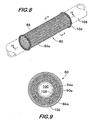
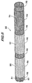
- Figures 8-11 illustrate another sleeve example not according to the invention.
- the sleeve comprises an elongated, flexible, continuous tube 82 formed of interlaced filamentary members 84, preferably interlaced by knitting.
- the filamentary members 84 of a first portion 86 of tube 82 are interlaced with first filamentary members 88, the filamentary members 88 having different characteristics than the base filamentary members 84.
- the filamentary members 84 of a second portion 90 of tube 82 are interlaced with second filamentary members 92, which may be the same or different from first filamentary members 88.
- Filamentary members 84 of a third portion 94 of tube 82 are interlaced with third filamentary members 96, which may be the same as or different from the first and second filamentary members 88 and 92.
- the various portions 86, 90 and 94 respectively defined by the interlaced filamentary members 88, 92 and 96 are positioned in spaced relation along tube 82 and separated by one another by regions 98 wherein the base filamentary members 84 comprising tube 82 are substantially exposed.
- the portions 86, 90 and 94 are preferably substantially equal in length to one another, but could also have different lengths. It is also understood that three portions are chosen for purposes of illustration, and there could be more or fewer portions depending upon the requirements driving the design.
- the sleeve 80 is formed by reverse folding the portions illustrated in Figure 11 so as to draw third portion 94 coaxially within second portion 90, and second portion 90 within first portion 86 so as to form multiple adjacent layers 94a, 90a and 86a surrounding and defining a central space 100 as best shown in Figure 9 .
- reverse folds 102 and 104 coincide with the separation regions 98 upon completion of the sleeve 80. Positioning the reverse fold at the separation regions avoids placing strain on brittle fibers which may comprise the filamentary members interlaced with the tube 82 to define the portions which form the adjacent layers.
- the separation regions also tend to be less bulky and more flexible than the portions 86, 90 and 94 and will facilitate the formation of the reverse folds and not substantially increase the diameter of the.sleeve 80. Separation regions 98 at the free ends of the tube 82 may be rolled back to form finished ends 106 for the sleeve 80.
- the tube 82 is knitted of base filamentary members 84 comprising a stainless steel, full-hard wire having a diameter of about 1.02 mm (0.04 inches).
- the innermost portion 94 of the sleeve 80 comprises a high-temperature resistant ceramic yarn, such as a silica yarn of 0.178 g/m (1600 denier) interknitted with the resilient base wire 84.
- the middle portion 90 is formed by interknitting with the base wire 84 a multifilament glass fiber yarn, such as an E-glass yarn of 0.022-0.667 g/m (200-6000 denier), although in some applications where extremely high temperatures are encountered, a silica yarn or other ceramic yarn may be employed, either alone or blended with glass fiber.
- a multifilament glass fiber yarn such as an E-glass yarn of 0.022-0.667 g/m (200-6000 denier)
- a silica yarn or other ceramic yarn may be employed, either alone or blended with glass fiber.
- the outermost portion 86 is comprised of E-glass of 0.022-0.667 g/m (200-6000 denier) interknitted with the wire 84 comprising the tube 82.
- An exemplary silica yarn is a multifilament texturized yarn of 0.178 g/m (1600 denier) as manufactured by BelChem of Ebisdorf, Germany, under the trademark belCoTex.
- Other ceramic yarns which may be employed are K-type silica yarns, such as that distributed in the U.S. under the tradename Siltex.
- Yarns in the portion 90 forming the intermediate layer 90a may be blended yarns of ceramic and glass fiber and are preferably texturized so that they are lofty or bulky, thereby improving insulation qualities.
- the sleeve is preferably fabricated in a continuous process as a single elongated, flexible tube 82.
- the tube 82 with its interlaced portions 86, 90 and 94 may be formed by braiding or weaving
- a striper knitter is used in carrying out a preferred method of manufacture.
- a striper knitter suitable for the purpose is manufactured by the Tritex International Limited of Leicester, England. Such a machine is a circular weft knitter, Model No. TX900, capable of knitting tubular fabric having a diameter of between about 2.22 cm-4.44 cm (0.875 and 1.75 inches) utilizing different types of yarn in different tubular sections.
- the striper knitter has separate groupings of needles which pick up different groups of yarns selectively so as to knit a tubular article with yarns having differing characteristics at locations spaced lengthwise along the article.
- the tube 82 is knitted with its portions 86, 90 and 94, it is placed on a mandrel for forming into the multi-layer sleeve 80. This is accomplished by reverse folding the first and second portions 86 and 90 over third portion 94 until the second portion 90 fully covers the third portion. The first portion 86 is then pulled back over the second and third portions 90 and 94. The end regions 98 at the free ends of the first and third portions 86 and 94 are then rolled back as shown in Figures 1 and 10 and crimped or fused to provide finished ends 106 for the sleeve.
- the sleeve 80 as described is simple to make and has been found to effectively insulate an EGR tube, with surface temperatures as high as about 982 °C (1800°F).
- the construction is relatively light in weight and extremely durable.
- the stainless steel wire forming the tube 82 disperses the heat effectively along the length of the sleeve 80, thereby avoiding degradation of the insulating yarns by eliminating hot spots. Since the sleeve is a continuous tubular member folded back upon itself a multiplicity of times to form multiple layers, end fray and delamination of the layers are avoided. Further, the separation regions 98 exclusively formed of knitted wire serve as attachment collars or grommets for attachment of the sleeve ends to the ends of an item being insulated.
- the flexible multi-layer sleeve according to the invention provides a lightweight, extremely durable and relatively inexpensive sleeve for receiving elongated items.
- the sleeve is versatile in that it can be tailored to any geometry and use virtually any type of filamentary members to adapt to extreme environments of heat, cold, vibration and shock for the protection and/or isolation of elongated items.
Landscapes
- Engineering & Computer Science (AREA)
- Textile Engineering (AREA)
- General Engineering & Computer Science (AREA)
- Mechanical Engineering (AREA)
- Knitting Of Fabric (AREA)
- Braiding, Manufacturing Of Bobbin-Net Or Lace, And Manufacturing Of Nets By Knotting (AREA)
- Insulating Bodies (AREA)
- Woven Fabrics (AREA)
- Gloves (AREA)
Abstract
Description
- This application is based on and claims priority to
U.S. Provisional Application No. 60/390,223, filed June 20, 2002 - This invention relates to flexible sleeving products and more particularly to a sleeve for insulating a tubular member such as an automotive exhaust gas recirculating device. Other exemplary applications of the invention include thermal protection of delicate tubular instruments and acoustic isolation of tubular devices.
- Lightweight sleeves knitted, woven or braided of bulky yarns for purposes such as the insulation of elongated tubular items are known in the art. An exemplary application of such sleeving is the insulation of exhaust gas recirculating devices so as to minimize the damage to other automotive components which such devices are in proximity to. A product of the type referred to is the sleeving of
U.S. Patent No. 5,671,649 in which spirally extending warp elements of relatively large diameter are utilized to stand a braided insulating sleeve away from the item being insulated, thereby creating an air gap in order to even out hot spots and thereby to increase the insulating capabilities of the product. Another form of sleeving is disclosed inU.S. Patent No. 5,849,379 . The sleeve disclosed in this patent combines a comb-like wire frame spaced between the item being insulated and the insulating material and also between layers of insulating material. The product is a split sleeve which facilitates the installation over previously installed tubular heat sources. The inner wire skeleton serves as a spacer layer for maintaining a space between the tubular heat source and the inner layer of the sleeve. Although the products described above have, to a large degree, satisfied the need for sleeving which protects nearby components from temperatures ranging from between about 538°C and 982°C (1000° F and 1800°F), the need persists for sleeving devices which combine the advantages of ease of manufacturer, low price, reduced weight and use of high-efficiency insulating yarns. - Published Japanese patent application number
JP11311396A - In a first aspect of the invention, there is provided a sleeve as set out in claim 1 hereof, and in a second aspect of the invention, there is provided a method of making such a sleeve as set out in
claim 3 thereof. -
-
Figure 1 is a side view of a sleeve according to the invention as shown prior to its formation into a multi-layered form; -
Figure 2 is a longitudinal sectional view of the sleeve shown inFigure 1 , the sleeve being shown after its formation into a multi-layered form; -
Figure 3 is a cross-sectional view taken at line 3-3 inFigure 2 ; -
Figure 4 is a side view of a sleeve shown prior to its formation into a multi-layered form; -
Figure 5 is a longitudinal sectional view of the sleeve shown inFigure 4 , the sleeve being shown after its formation into a multi-layered form; -
Figure 6 is a side view of a sleeve shown prior to its formation into multi-layered form; -
Figure 7 is a longitudinal sectional view of the sleeve shown inFigure 6 , the sleeve being shown after its formation into a multi-layered form; -
Figure 8 is a perspective view showing a multi-layered sleeve; -
Figure 9 is a cross-sectional view taken at line 9-9 ofFigure 8 ; -
Figure 10 is a longitudinal sectional view of the sleeve taken at line 10-10 ofFigure 8 ; and -
Figure 11 is a perspective view of a multi-sectioned sleeve shown prior to its formation into multi-layered form. -
Figures 1 and 2 show asleeve 10 according to the invention.Sleeve 10 comprises a first flexibletubular segment 12 having oppositely disposedends segment 12 being formed from interlacedfilamentary members 18.Filamentary members 18 are preferably interlaced by knitting to give thesleeve 10 flexibility and elasticity to allow it to conform closely to the shape and path of an elongated substrate.Filamentary members 18 have certain characteristics, which may include the type of material from which they are comprised, the style of interlacing, for example, a particular type of knit or weave or a particular density of knit or weave, or a particular property such as strength, resistance to abrasion, resistance to heat transfer, inflammability or the ability to damp vibration. These characteristics are chosen in the context of a particular environment and function which the sleeve is intended to perform as described below. -
Sleeve 10 comprises a second flexibletubular segment 20, also having oppositely disposedends filamentary members 26, preferably knitted and having different characteristics from thefilamentary members 18.End 22 ofsegment 20 is attached toend 16 ofsegment 12, the segments being preferably integrally joined by interknitting of thefilamentary members free ends segments welts sleeve 10 to maintain the position of the sleeve on the substrate. -
Figure 1 shows thesleeve 10 as knitted but before being formed into a multilayer configuration. Thesleeve 10 is completed as shown inFigure 2 by folding one of the segments, in thisexample segment 20, circumferentially inwardly, thereby forming areverse fold 32 and drawing thesegment 20 coaxially within thecentral space 34 defined by thefirst segment 12. Thesegment 20 defines acentral space 36 for receiving the elongated substrates to be protected, such as an automotive exhaust gas recirculating (EGR) tube. Together, thesegments adjacent layers central space 36. It is also feasible to draw thesegment 12 within thecentral space 36 defined by thesegment 20. -
Segments reverse fold 32 is positioned between the segments andends segments reverse fold 32 need not fall between the segments, and theends - As noted above,
filamentary members sleeve 10 in response to the function and/or the environment to which the sleeve will be subjected. For example, if the sleeve is to insulate an EGR tube, then it is preferred to knit theinner segment 20 from filamentary members having high-temperature resistance, such as glass, quartz or other mineral fibers. High-temperature resistance is necessary since theinner segment 20 will be in contact with the EGR tube, which can reach temperatures in excess of 538°C (1000°F). However, glass fibers are a major skin irritant when handled during installation. To avoid irritation, theouter segment 12 is knitted from DREF yarns having a glass fiber core and a coating of non-irritating fibers such as para-aramids. Oxidized polyacrylonitrile fibers, which have high-temperature resistance but are non-irritants may also be used to knitouter segment 12. Although it is possible to knit a sleeve entirely from DREF yarns, it is more economical to use the more expensive DREF or oxidized polyacrylonitrile fibers only on theouter segment 12 where their non-irritating characteristics are needed, confining the less expensive but irritating glass fibers to theinner segment 20. To ensure that the technician installing the sleeve has little to no chance of coming into contact with the irritatingfilamentary members 26 comprising theinner segment 20, it is advantageous to form thewelt 30 on theinner segment 20 from the same material as used for theouter segment 12. - High-temperature applications may require augmenting the insulating properties of the
sleeve 10. According to the invention this is accomplished by using a rib knit to construct either or bothsegments Figure 3 ,ribs 35 may extend inwardly fromouter segment 12 and/or outwardly frominner segment 20 to act as spacers to formair pockets 38 between thetubes Additional ribs 35 may extend outwardly fromouter segment 12 and/or inwardly frominner segment 20. Such ribs providefurther air pockets 38 between theinner segment 20 and an item, such as the EGR tube which the sleeve surrounds, or prevents direct contact with theouter segment 12 by acting as bumpers. Bumpers are useful to prevent abrasion of theouter segment 12 and absorb impact. -
Figures 4 and 5 show an example not according to the invention claimed comprising asleeve 40 formed of three flexibletubular segments segments filamentary members sleeve 40 into its final form as shown inFigure 5 , reverse folds 54 and 56 are formed in either or bothend segments middle segment 44 by circumferentially folding theend segments middle segment 44. Thesegments segment 44, thereby formingsleeve 40 havingmultiple layers central space 55. As with the sleeve embodiment shown inFigures 1 and 2 , either one or both of theinner segments outer segment 44.Sleeve 40 is preferably a weltless design with the free ends of thetubes segments segment 44, but other length ratios are also feasible. In an alternate embodiment,segments tube 44 to form themulti-layer sleeve 40. -
Figures 6 and 7 show yet another example not according to the invention on claimed,sleeve 58, formed of three flexibletubular segments segments welts Figure 7 , thesleeve 58 is configured by forming two reverse folds 70 and 72, wherein the segments are circumferentially folded to allowsegment 62 to be drawn within thesegment 60 andsegment 64 to be drawn within thesegment 62 to form a sleeve having threeadjacent layers central space 73. - The
filamentary members segments Welts sleeve 58 and act as elastic cinches to secure the sleeve to an item received within thecentral space 73. - Manufacture of sleeves according to the invention is advantageously accomplished on circular knitting machines having multiple feeders capable of handling multiple different filamentary members and capable of knitting different stitch types and different stitch densities. In one example, wherein the material properties of the segments are different from one another, a first segment is knitted using a filamentary member comprised of a first material held on a first feeder of the machine. When the first segment is completed, a second feeder is brought into action which introduces a second filamentary member of a different material to the needles. The first feeder drops out of cooperation with the needles, the first filamentary member is cut and the knitting proceeds with the second filamentary member on the second feeder. This process may be repeated for as many times as required depending upon the number of segments needed (corresponding to the number of layers in the sleeve). Filamentary members, once taken out of action, may be reintroduced into the knitting process, as, for example, when a welt is to be knitted from a first material on the end of a segment comprised of a second material as described above with reference to
Figures 1 and 2 . Other characteristics, including parameters such as knit density or stitch type, may be varied in addition to or instead of material type during the knitting process by controlling the actions of the needles and hooks. This is usually accomplished by programming the machine to knit a predetermined number of courses of a particular stitch or knit density, followed by another number of courses having a different stitch type and/or density. -
Figures 8-11 illustrate another sleeve example not according to the invention. As best shown inFigure 11 , the sleeve comprises an elongated, flexible,continuous tube 82 formed of interlacedfilamentary members 84, preferably interlaced by knitting. Thefilamentary members 84 of afirst portion 86 oftube 82 are interlaced with firstfilamentary members 88, thefilamentary members 88 having different characteristics than the basefilamentary members 84. Thefilamentary members 84 of asecond portion 90 oftube 82 are interlaced with secondfilamentary members 92, which may be the same or different from firstfilamentary members 88. Filamentarymembers 84 of athird portion 94 oftube 82 are interlaced with thirdfilamentary members 96, which may be the same as or different from the first and secondfilamentary members various portions filamentary members tube 82 and separated by one another byregions 98 wherein the basefilamentary members 84 comprisingtube 82 are substantially exposed. Theportions - As shown in
Figure 10 , thesleeve 80 according to the invention is formed by reverse folding the portions illustrated inFigure 11 so as to drawthird portion 94 coaxially withinsecond portion 90, andsecond portion 90 withinfirst portion 86 so as to form multipleadjacent layers central space 100 as best shown inFigure 9 . Preferably, as shown inFigure 10 , reverse folds 102 and 104 coincide with theseparation regions 98 upon completion of thesleeve 80. Positioning the reverse fold at the separation regions avoids placing strain on brittle fibers which may comprise the filamentary members interlaced with thetube 82 to define the portions which form the adjacent layers. The separation regions also tend to be less bulky and more flexible than theportions the.sleeve 80.Separation regions 98 at the free ends of thetube 82 may be rolled back to form finished ends 106 for thesleeve 80. - In a specific example of
sleeve 80 which is intended to insulate atubular heat source 108, such as an EGR tube in an automobile, thetube 82 is knitted of basefilamentary members 84 comprising a stainless steel, full-hard wire having a diameter of about 1.02 mm (0.04 inches). Theinnermost portion 94 of thesleeve 80 comprises a high-temperature resistant ceramic yarn, such as a silica yarn of 0.178 g/m (1600 denier) interknitted with theresilient base wire 84. Themiddle portion 90 is formed by interknitting with the base wire 84 a multifilament glass fiber yarn, such as an E-glass yarn of 0.022-0.667 g/m (200-6000 denier), although in some applications where extremely high temperatures are encountered, a silica yarn or other ceramic yarn may be employed, either alone or blended with glass fiber. In theillustrative sleeve 80 having three layers, theoutermost portion 86 is comprised of E-glass of 0.022-0.667 g/m (200-6000 denier) interknitted with thewire 84 comprising thetube 82. - An exemplary silica yarn is a multifilament texturized yarn of 0.178 g/m (1600 denier) as manufactured by BelChem of Ebisdorf, Germany, under the trademark belCoTex. Other ceramic yarns which may be employed are K-type silica yarns, such as that distributed in the U.S. under the tradename Siltex. Yarns in the
portion 90 forming theintermediate layer 90a may be blended yarns of ceramic and glass fiber and are preferably texturized so that they are lofty or bulky, thereby improving insulation qualities. - With reference to
Figure 11 , the sleeve is preferably fabricated in a continuous process as a single elongated,flexible tube 82. Although thetube 82 with its interlacedportions - Once the
tube 82 is knitted with itsportions multi-layer sleeve 80. This is accomplished by reverse folding the first andsecond portions third portion 94 until thesecond portion 90 fully covers the third portion. Thefirst portion 86 is then pulled back over the second andthird portions end regions 98 at the free ends of the first andthird portions Figures 1 and10 and crimped or fused to provide finished ends 106 for the sleeve. Thesleeve 80 as described is simple to make and has been found to effectively insulate an EGR tube, with surface temperatures as high as about 982 °C (1800°F). The construction is relatively light in weight and extremely durable. The stainless steel wire forming thetube 82 disperses the heat effectively along the length of thesleeve 80, thereby avoiding degradation of the insulating yarns by eliminating hot spots. Since the sleeve is a continuous tubular member folded back upon itself a multiplicity of times to form multiple layers, end fray and delamination of the layers are avoided. Further, theseparation regions 98 exclusively formed of knitted wire serve as attachment collars or grommets for attachment of the sleeve ends to the ends of an item being insulated. - The flexible multi-layer sleeve according to the invention provides a lightweight, extremely durable and relatively inexpensive sleeve for receiving elongated items. The sleeve is versatile in that it can be tailored to any geometry and use virtually any type of filamentary members to adapt to extreme environments of heat, cold, vibration and shock for the protection and/or isolation of elongated items.
Claims (3)
- A sleeve (10) for receiving elongate items, said sleeve comprising a flexible first tubular segment (12) having opposite ends (14, 16) and comprising filamentary members (18) interlaced together and a flexible second tubular segment (20) of filamentary members (26) interlaced together and having opposite ends (22, 24), one of said opposite ends of the first segment being joined to one end of the second segment and one of said first and second tubular segments being drawn coaxially within the other of said first and second tubular segments to form inner and outer adjacent layers (20a, 12a) surrounding a central space (34) for receiving said items, a reverse fold (32) being formed and defining one end of the sleeve, 1 characterised in that a plurality of ribs (35) extends lengthwise along at least one segment and faces towards and engages the other segment, said ribs (35) separating said layers of the sleeve and forming a plurality of air pockets (38) therebetween.
- A sleeve (10, 40) according to claim 1 wherein said filamentary members (18, 26) of said at least one segment (18, 20) are interlaced by knitting and the ribs (35) are formed integrally with said at least one segment by knitting in a. rib-knit stitch.
- A method of forming a sleeve (10, 40) for receiving elongated items, the method comprising the steps of:selecting first filamentary members (18) ; selecting a first technique for interlacing said first filamentary members; selecting first parameters related to said first technique for interlacing said first filamentary members;interlacing said first filamentary members using said selected first technique and first parameters to form a first flexible tubular segment (12) having oppositely disposed ends; selecting second filamentary members (26);selecting a second technique for interlacing said second filamentary members; selecting second parameters related to said second technique for interlacing said first filamentary members; interlacing said second filamentary members using said selected second technique and second parameters to form a second flexible tubular segment (20), said second filamentary members being continuously interlaced with said fist filamentary members to form said second flexible tubular segment continuously from one end of said first flexible tubular segment; drawing said second tubular segment coaxially within said first tubular segment to form inner and outer layers adjacent one another surrounding a central space, a reverse fold being formed and defining one end of said sleeve, characterised in that the method includes the further step of using a rib knit to form either or both of the first and second tubular segments thereby providing a plurality of ribs (35) arranged lengthwise along at least one segment such that said ribs face towards and engage the other segment thus separating said layers of the sleeve to form a plurality of air pockets (38) therebetween.
Applications Claiming Priority (3)
| Application Number | Priority Date | Filing Date | Title |
|---|---|---|---|
| US39022302P | 2002-06-20 | 2002-06-20 | |
| US390223P | 2002-06-20 | ||
| PCT/US2003/019530 WO2004001780A2 (en) | 2002-06-20 | 2003-06-20 | Multiple layer insulating sleeve |
Publications (3)
| Publication Number | Publication Date |
|---|---|
| EP1552049A2 EP1552049A2 (en) | 2005-07-13 |
| EP1552049A4 EP1552049A4 (en) | 2006-05-31 |
| EP1552049B1 true EP1552049B1 (en) | 2012-03-28 |
Family
ID=30000528
Family Applications (1)
| Application Number | Title | Priority Date | Filing Date |
|---|---|---|---|
| EP03739236A Expired - Lifetime EP1552049B1 (en) | 2002-06-20 | 2003-06-20 | Multiple layer insulating sleeve |
Country Status (9)
| Country | Link |
|---|---|
| US (1) | US6978643B2 (en) |
| EP (1) | EP1552049B1 (en) |
| JP (1) | JP4428655B2 (en) |
| CN (1) | CN100436678C (en) |
| AU (1) | AU2003245607A1 (en) |
| BR (1) | BR0311999A (en) |
| CA (1) | CA2490090A1 (en) |
| MX (1) | MXPA05000198A (en) |
| WO (1) | WO2004001780A2 (en) |
Families Citing this family (62)
| Publication number | Priority date | Publication date | Assignee | Title |
|---|---|---|---|---|
| CN1502331A (en) * | 1993-07-19 | 2004-06-09 | Ѫ�ܼ���ҩ�﹫˾ | Antiangiogenic compositions and methods of use |
| US7575561B2 (en) * | 2004-01-26 | 2009-08-18 | Knit Rite, Inc. | Above knee shrinker |
| US7395680B2 (en) * | 2004-07-20 | 2008-07-08 | Federal Mogul Worldwide, Inc. | Self-curling knitted sleeve and method of fabrication |
| TW200624617A (en) * | 2004-07-20 | 2006-07-16 | Federal Mogul World Wide Inc | Self-curling sleeve |
| FR2876778B1 (en) * | 2004-10-15 | 2007-05-04 | Fed Mogul Systems Prot Group S | TEXTILE ELEMENT FOR PROTECTING A PLASTIC SUPPORT |
| US8070705B2 (en) * | 2005-06-21 | 2011-12-06 | Hipsaver, Incorporated | Protective device using a spacer fabric |
| FR2897877B1 (en) * | 2006-02-28 | 2008-07-11 | Fed Mogul Systems Prot Group S | PROTECTIVE SHOCK FOR THE IMPACT OF A PIPE, IN PARTICULAR FOR FUEL DRIVING |
| US7600539B2 (en) * | 2006-03-03 | 2009-10-13 | Federal-Mogul World Wide, Inc | Low profile textile wire bundler sleeve |
| ATE447095T1 (en) | 2006-05-10 | 2009-11-15 | Metal Textiles Corp | INSULATING SLEEVE WITH WIRE MESH AND WIRE MESH |
| USD601336S1 (en) * | 2006-09-18 | 2009-10-06 | Goldtoemoretz, L.L.C. | Assembly of sock components |
| US7874184B2 (en) * | 2007-08-23 | 2011-01-25 | Federal-Mogul Powertrain, Inc. | Thermal protection sleeve with knit thermal protection features and method of construction thereof |
| US7757517B2 (en) * | 2007-08-23 | 2010-07-20 | Federal-Mogul Powertrain, Inc. | Protective sleeve with knitted opening and method on construction |
| US8038133B2 (en) * | 2007-09-13 | 2011-10-18 | Mcpherson Mathew A | Coaxial tube damper |
| US9028937B2 (en) | 2008-01-07 | 2015-05-12 | Federal-Mogul Powertrain, Inc. | Multilayer protective textile sleeve and method of construction |
| US7669442B1 (en) * | 2009-01-26 | 2010-03-02 | E. I. Du Pont De Nemours And Company | Cut-resistant gloves containing fiberglass and para-aramid |
| US8151682B2 (en) * | 2009-01-26 | 2012-04-10 | Boston Scientific Scimed, Inc. | Atraumatic stent and method and apparatus for making the same |
| US7934397B2 (en) * | 2009-01-26 | 2011-05-03 | E.I. Du Pont De Nemours And Company | Cut-resistant gloves containing fiberglass and para-aramid |
| US7934395B2 (en) * | 2009-01-26 | 2011-05-03 | E. I. Du Pont De Nemours And Company | Cut-resistant gloves containing fiberglass and para-aramid |
| US7934396B2 (en) * | 2009-01-26 | 2011-05-03 | E. I. Du Pont De Nemours And Company | Cut-resistant gloves containing fiberglass and para-aramid |
| US7934394B2 (en) * | 2009-01-26 | 2011-05-03 | E. I. Du Pont De Nemours And Company | Cut-resistant gloves containing fiberglass and para-aramid |
| EP2440828A4 (en) * | 2009-06-12 | 2017-11-15 | Federal-Mogul Powertrain, Inc. | Textile sleeve with high temperature abrasion resistant coating and methods of assembly, construction and curing thereof |
| EP2560256B1 (en) * | 2010-04-16 | 2022-06-08 | Relats, S.A. | Protective tube |
| DE102010016980B4 (en) * | 2010-05-18 | 2014-04-03 | Alfred Buck | Knitted body, use and method for its production |
| JP2013544341A (en) * | 2010-09-30 | 2013-12-12 | フェデラル−モーグル パワートレイン インコーポレイテッド | Knitted sleeve with a knitted barrier extension having a barrier therein and method of construction thereof |
| JP5709511B2 (en) * | 2010-12-20 | 2015-04-30 | 株式会社島精機製作所 | Three-dimensional knitted fabric, its knitting method and supporter |
| US9365960B2 (en) * | 2011-04-20 | 2016-06-14 | Nike, Inc. | Sock with zones of varying layers |
| US8100315B1 (en) * | 2011-07-11 | 2012-01-24 | Tennco Automotive Operating Company Inc. | Method of insulating an exhaust device |
| US8557358B1 (en) * | 2011-08-22 | 2013-10-15 | The United States Of America As Represented By The Secretary Of The Navy | Rolling textile protective system for textile structural members |
| BR112014004033A2 (en) * | 2011-08-22 | 2017-06-13 | Federal-Mogul Powertrain Inc | radially foldable and expandable textile sleeve, and construction methods thereof |
| US8621975B2 (en) * | 2011-09-20 | 2014-01-07 | Aga Medical Corporation | Device and method for treating vascular abnormalities |
| US9039752B2 (en) | 2011-09-20 | 2015-05-26 | Aga Medical Corporation | Device and method for delivering a vascular device |
| RU2618419C2 (en) * | 2012-03-01 | 2017-05-03 | Федерал-Могал Пауэртрейн, Инк. | Protective textile shell for elongated objects protection and method for its manufacture |
| US9976687B2 (en) | 2012-05-18 | 2018-05-22 | Saprex, Llc | Breathable multi-component exhaust insulation system |
| ES2439818B1 (en) * | 2012-07-23 | 2014-12-29 | Relats, S.A. | TUBULAR PROTECTION COVER |
| US10508583B2 (en) * | 2012-08-30 | 2019-12-17 | Bosal Emission Control Systems Nv | Composite exhaust element |
| US9388515B2 (en) | 2012-09-28 | 2016-07-12 | Saprex, Llc | Heat curable composite textile |
| USD712995S1 (en) | 2012-11-27 | 2014-09-09 | Mcp Ip, Llc | Vibration damper |
| US9360271B1 (en) | 2013-03-14 | 2016-06-07 | Mcp Ip, Llc | Vibration damper |
| WO2014140207A1 (en) | 2013-03-15 | 2014-09-18 | Delfingen Fr-Anteuil | Elongate self-closing sleeve for protecting elongate members |
| US20140311611A1 (en) * | 2013-03-15 | 2014-10-23 | Southern Weaving Company | Protective sleeve |
| US20150144726A1 (en) * | 2013-11-26 | 2015-05-28 | Warren E. Dennis | Electrical cord retaining sheath |
| JP6271282B2 (en) * | 2014-02-14 | 2018-01-31 | 株式会社豊田自動織機 | Insulation sleeve |
| KR20160124128A (en) | 2014-02-20 | 2016-10-26 | 페더럴-모걸 파워트레인 엘엘씨 | Nonkinking wrappable knit sleeve and method of construction thereof |
| US9863070B2 (en) * | 2014-12-08 | 2018-01-09 | Federal-Mogul Powertrain Llc | Tubular protective sleeve with curl resistant knit ends and method of construction thereof |
| US20160245431A1 (en) * | 2015-02-20 | 2016-08-25 | Gates Corporation | Safety apparatus and methods for high-pressure conduits |
| US10840681B2 (en) * | 2015-07-30 | 2020-11-17 | Federal-Mogul Powertrain Llc | Thermal sleeve with positioning member, assembly therewith and method of construction thereof |
| JP6275095B2 (en) * | 2015-09-29 | 2018-02-07 | 本田技研工業株式会社 | Exhaust muffler |
| US12051527B2 (en) * | 2016-01-20 | 2024-07-30 | Federal-Mogul Powertrain Llc | Abrasion resistant textile sleeve, improved multifilament yarn therefor and methods of construction thereof |
| CN109073134B (en) | 2016-04-15 | 2021-04-02 | 萨布雷克斯有限责任公司 | Composite isolation system |
| US10982355B2 (en) | 2016-07-25 | 2021-04-20 | Federal-Mogul Powertrain Llc | Knit tubular protective sleeve and method of construction thereof |
| JP6940608B2 (en) | 2016-11-18 | 2021-09-29 | サプレックス,リミテッド・ライアビリティ・カンパニー | Composite insulation system |
| US10578001B2 (en) * | 2017-02-09 | 2020-03-03 | Federal-Mogul Powertrain Llc | Thermally insulative, durable, reflective convoluted sleeve and method of construction thereof |
| USD892430S1 (en) * | 2017-09-12 | 2020-08-11 | Art Design Works LLC | Scarf |
| USD903837S1 (en) * | 2018-04-24 | 2020-12-01 | Kevin Hughes | Septic system pipe cover |
| US11925230B2 (en) * | 2019-04-05 | 2024-03-12 | Drymax Technologies, Inc. | Chinstrap sock with metal-containing yarn |
| CN111544169B (en) * | 2020-05-13 | 2021-08-03 | 东华大学 | Integral braided stent-graft edge closing process |
| TWD211495S (en) | 2020-08-03 | 2021-05-11 | 黃美菁 | Braided outer tube for coating water pipe |
| US12503797B2 (en) * | 2021-07-13 | 2025-12-23 | Systems Protection Group Us Llc | Circumferentially continuous, fire suppressing, dielectric sleeve |
| WO2023288246A1 (en) * | 2021-07-13 | 2023-01-19 | Federal-Mogul Powertrain Llc | Circumferentially continuous, fire suppressing, dielectric sleeve |
| US20230024423A1 (en) * | 2021-07-23 | 2023-01-26 | Lydall Thermal/Acoustical, Inc. | Multi-Layer Insulator for Thermal Run-Away Containment in Lithium-Ion Batteries |
| CN120322595A (en) * | 2022-12-22 | 2025-07-15 | 系统保护集团美国有限责任公司 | Circumferentially continuous, axially and radially stretchable, flame retardant, puncture resistant dielectric braided sleeve |
| USD1101292S1 (en) | 2025-06-12 | 2025-11-04 | Drymax Technologies, Inc. | Head gear sleeve |
Family Cites Families (21)
| Publication number | Priority date | Publication date | Assignee | Title |
|---|---|---|---|---|
| US2222522A (en) * | 1939-03-20 | 1940-11-19 | Crescent Woolen Mills Co | Bearing packing |
| US2436318A (en) * | 1945-02-02 | 1948-02-17 | Scott & Williams Inc | Circular knitting machine |
| US2881603A (en) * | 1954-04-26 | 1959-04-14 | Scott & Williams Inc | Knitting machine and method of knitting |
| US3862878A (en) * | 1970-04-02 | 1975-01-28 | Kimikazu Azuma | Method of Manufacturing Foamed Plastic Tubular Nets and Apparatus Pertinent Thereto |
| US4104892A (en) * | 1976-11-15 | 1978-08-08 | Thorneburg Hosiery Mill, Inc. | Cushioned sole tube sock and method |
| US4341096A (en) * | 1980-08-06 | 1982-07-27 | Kayser-Roth Hosiery, Inc. | Sock with triple layer fabric in foot and method |
| US4615188A (en) * | 1981-02-13 | 1986-10-07 | Foster-Boyd, Inc. | Two-ply athletic sock |
| US4571960A (en) * | 1982-09-30 | 1986-02-25 | Foster-Boyd, Inc. | Two-ply athletic sock with low-friction interface surfaces |
| DE3334770C2 (en) * | 1983-09-26 | 1994-03-31 | Kabelmetal Electro Gmbh | Conduit for the discharge of frozen media |
| US4931326A (en) * | 1988-04-25 | 1990-06-05 | Davlyn Manufacturing Co., Inc. | Reinforced flexible plastic tubing and methods of manufacture |
| GB8903641D0 (en) | 1989-02-17 | 1989-04-05 | Courtaulds Plc | Flexible fabric thermal insulators |
| US5617900A (en) * | 1993-07-20 | 1997-04-08 | Davlyn Manufacturing Co., Inc. | Multilayer flexibility resilient thermal shielding sleeves |
| US5373713A (en) * | 1993-09-20 | 1994-12-20 | J. E. Morgan Knitting Mills, Inc. | Bi-ply fabric construction |
| US5744206A (en) * | 1994-04-06 | 1998-04-28 | Vitrica, S.A. De C.V. | Braided sleeving with rib strands |
| US5509282A (en) * | 1994-10-14 | 1996-04-23 | Ferrell, Jr.; James M. | Double cuffed hosiery |
| EP0877892B1 (en) | 1996-02-06 | 1999-11-24 | Federal-Mogul Systems Protection Group Inc. | Heat reflective sleeve |
| US5636533A (en) * | 1996-03-12 | 1997-06-10 | Domestic Fabrics Corporation | Composite fabric with integral thermal layer |
| US5778702A (en) * | 1996-09-06 | 1998-07-14 | Wrightenberry; Jerry O. | Double ply sock and method of making same |
| US5675992A (en) * | 1996-09-09 | 1997-10-14 | Wrightenberry; Jerry O. | Double layer sock with attached liner and method for forming same |
| JP3417841B2 (en) * | 1998-04-28 | 2003-06-16 | ニチアス株式会社 | Insulation sleeve for high heat piping |
| CN2494609Y (en) * | 2001-08-27 | 2002-06-12 | 管少英 | Leg cover |
-
2003
- 2003-06-20 JP JP2004516039A patent/JP4428655B2/en not_active Expired - Lifetime
- 2003-06-20 EP EP03739236A patent/EP1552049B1/en not_active Expired - Lifetime
- 2003-06-20 CA CA002490090A patent/CA2490090A1/en not_active Abandoned
- 2003-06-20 AU AU2003245607A patent/AU2003245607A1/en not_active Abandoned
- 2003-06-20 MX MXPA05000198A patent/MXPA05000198A/en active IP Right Grant
- 2003-06-20 CN CNB038196972A patent/CN100436678C/en not_active Expired - Lifetime
- 2003-06-20 BR BRPI0311999-8A patent/BR0311999A/en not_active IP Right Cessation
- 2003-06-20 WO PCT/US2003/019530 patent/WO2004001780A2/en not_active Ceased
- 2003-06-20 US US10/600,944 patent/US6978643B2/en not_active Expired - Lifetime
Also Published As
| Publication number | Publication date |
|---|---|
| US20040003630A1 (en) | 2004-01-08 |
| WO2004001780A3 (en) | 2005-05-12 |
| AU2003245607A1 (en) | 2004-01-06 |
| CA2490090A1 (en) | 2003-12-31 |
| AU2003245607A8 (en) | 2004-01-06 |
| CN1675422A (en) | 2005-09-28 |
| WO2004001780A2 (en) | 2003-12-31 |
| MXPA05000198A (en) | 2005-06-06 |
| EP1552049A4 (en) | 2006-05-31 |
| US6978643B2 (en) | 2005-12-27 |
| BR0311999A (en) | 2007-11-06 |
| JP4428655B2 (en) | 2010-03-10 |
| CN100436678C (en) | 2008-11-26 |
| JP2005530061A (en) | 2005-10-06 |
| EP1552049A2 (en) | 2005-07-13 |
Similar Documents
| Publication | Publication Date | Title |
|---|---|---|
| US6978643B2 (en) | Multiple layer insulating sleeve | |
| US12252820B2 (en) | Single-layer ceramic-based knit fabric for high temperature bulb seals | |
| EP2016260B1 (en) | Insulating sleeve with wire mesh and wire cloth | |
| US6711920B2 (en) | Knit convolute protective sleeve | |
| US11053615B2 (en) | Metal alloy knit fabric for high temperature insulating materials | |
| EP3368710B1 (en) | Self-wrapping, braided textile sleeve with self-sustaining expanded and contracted states and method of construction thereof | |
| MXPA97006071A (en) | Protective sleeve with warp spacers | |
| KR20190039241A (en) | Impact resistant, shrinkable tubular sleeve and method of making same | |
| WO2002084001A1 (en) | Knitted multi-property protective sleeve | |
| EP3593023A1 (en) | Abrasion resistant braided convolute textile sleeve and method of construction thereof | |
| JP2018503753A (en) | Tubular protective sleeve with curl resistant knitted end, construction method thereof and installation method thereof | |
| KR100993177B1 (en) | Multilayer insulation sleeve | |
| EP3485074A1 (en) | Knit textile sleeve with self-sustaining expanded and contracted states and method of construction thereof |
Legal Events
| Date | Code | Title | Description |
|---|---|---|---|
| PUAI | Public reference made under article 153(3) epc to a published international application that has entered the european phase |
Free format text: ORIGINAL CODE: 0009012 |
|
| 17P | Request for examination filed |
Effective date: 20050111 |
|
| AK | Designated contracting states |
Kind code of ref document: A2 Designated state(s): AT BE BG CH CY CZ DE DK EE ES FI FR GB GR HU IE IT LI LU MC NL PT RO SE SI SK TR |
|
| AX | Request for extension of the european patent |
Extension state: AL LT LV MK |
|
| DAX | Request for extension of the european patent (deleted) | ||
| RBV | Designated contracting states (corrected) |
Designated state(s): DE ES FR GB |
|
| A4 | Supplementary search report drawn up and despatched |
Effective date: 20060419 |
|
| 17Q | First examination report despatched |
Effective date: 20060904 |
|
| GRAP | Despatch of communication of intention to grant a patent |
Free format text: ORIGINAL CODE: EPIDOSNIGR1 |
|
| GRAS | Grant fee paid |
Free format text: ORIGINAL CODE: EPIDOSNIGR3 |
|
| GRAA | (expected) grant |
Free format text: ORIGINAL CODE: 0009210 |
|
| AK | Designated contracting states |
Kind code of ref document: B1 Designated state(s): DE ES FR GB |
|
| REG | Reference to a national code |
Ref country code: GB Ref legal event code: FG4D |
|
| REG | Reference to a national code |
Ref country code: DE Ref legal event code: R096 Ref document number: 60340421 Country of ref document: DE Effective date: 20120524 |
|
| REG | Reference to a national code |
Ref country code: DE Ref legal event code: R082 Ref document number: 60340421 Country of ref document: DE Representative=s name: SCHUMACHER & WILLSAU PATENTANWALTSGESELLSCHAFT, DE |
|
| PLBE | No opposition filed within time limit |
Free format text: ORIGINAL CODE: 0009261 |
|
| STAA | Information on the status of an ep patent application or granted ep patent |
Free format text: STATUS: NO OPPOSITION FILED WITHIN TIME LIMIT |
|
| GBPC | Gb: european patent ceased through non-payment of renewal fee |
Effective date: 20120628 |
|
| 26N | No opposition filed |
Effective date: 20130103 |
|
| REG | Reference to a national code |
Ref country code: DE Ref legal event code: R097 Ref document number: 60340421 Country of ref document: DE Effective date: 20130103 |
|
| PG25 | Lapsed in a contracting state [announced via postgrant information from national office to epo] |
Ref country code: ES Free format text: LAPSE BECAUSE OF FAILURE TO SUBMIT A TRANSLATION OF THE DESCRIPTION OR TO PAY THE FEE WITHIN THE PRESCRIBED TIME-LIMIT Effective date: 20120709 Ref country code: GB Free format text: LAPSE BECAUSE OF NON-PAYMENT OF DUE FEES Effective date: 20120628 |
|
| REG | Reference to a national code |
Ref country code: FR Ref legal event code: PLFP Year of fee payment: 13 |
|
| REG | Reference to a national code |
Ref country code: FR Ref legal event code: PLFP Year of fee payment: 14 |
|
| REG | Reference to a national code |
Ref country code: FR Ref legal event code: PLFP Year of fee payment: 15 |
|
| REG | Reference to a national code |
Ref country code: FR Ref legal event code: PLFP Year of fee payment: 16 |
|
| PGFP | Annual fee paid to national office [announced via postgrant information from national office to epo] |
Ref country code: FR Payment date: 20220517 Year of fee payment: 20 Ref country code: DE Payment date: 20220512 Year of fee payment: 20 |
|
| REG | Reference to a national code |
Ref country code: DE Ref legal event code: R071 Ref document number: 60340421 Country of ref document: DE |