EP1551161A1 - Analog subscriber board - Google Patents
Analog subscriber board Download PDFInfo
- Publication number
- EP1551161A1 EP1551161A1 EP04027367A EP04027367A EP1551161A1 EP 1551161 A1 EP1551161 A1 EP 1551161A1 EP 04027367 A EP04027367 A EP 04027367A EP 04027367 A EP04027367 A EP 04027367A EP 1551161 A1 EP1551161 A1 EP 1551161A1
- Authority
- EP
- European Patent Office
- Prior art keywords
- relay
- contact point
- subscriber
- movable contact
- subscriber line
- Prior art date
- Legal status (The legal status is an assumption and is not a legal conclusion. Google has not performed a legal analysis and makes no representation as to the accuracy of the status listed.)
- Granted
Links
- 238000012360 testing method Methods 0.000 abstract description 87
- 238000012544 monitoring process Methods 0.000 abstract description 36
- 230000003068 static effect Effects 0.000 description 33
- 238000010586 diagram Methods 0.000 description 19
- 230000003247 decreasing effect Effects 0.000 description 3
- 230000002159 abnormal effect Effects 0.000 description 1
- 238000004519 manufacturing process Methods 0.000 description 1
Images

Classifications
-
- H—ELECTRICITY
- H04—ELECTRIC COMMUNICATION TECHNIQUE
- H04M—TELEPHONIC COMMUNICATION
- H04M3/00—Automatic or semi-automatic exchanges
- H04M3/22—Arrangements for supervision, monitoring or testing
- H04M3/26—Arrangements for supervision, monitoring or testing with means for applying test signals or for measuring
- H04M3/28—Automatic routine testing ; Fault testing; Installation testing; Test methods, test equipment or test arrangements therefor
- H04M3/30—Automatic routine testing ; Fault testing; Installation testing; Test methods, test equipment or test arrangements therefor for subscriber's lines, for the local loop
-
- H—ELECTRICITY
- H04—ELECTRIC COMMUNICATION TECHNIQUE
- H04M—TELEPHONIC COMMUNICATION
- H04M3/00—Automatic or semi-automatic exchanges
- H04M3/005—Interface circuits for subscriber lines
Definitions
- the present invention relates to a solution of line and relay in an analog subscriber board used in a voice network, more specifically, to a solution of line and relay in an analog subscriber board in which the number of the relay is reduced.
- each subscriber group has a common ring bus and a test bus. Moreover, each subscriber in the subscriber group has an independent subscriber line interface circuit ( SLIC ).
- SLIC subscriber line interface circuit
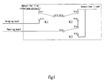
- Fig.1 is a schematic diagram showing the connection of relays on an analog subscriber board of the prior art, wherein only three relays K1, K2, K3 relevant directly to controlling and realizing the various functions of a voice network, as well as ring bus 2, test bus 3, subscriber line interface circuit ( SLIC ) 1 and subscriber line 4 are shown, while other parts being not in the drawing.
- subscriber line interface circuit ( SLIC ) 1 is connected to movable contact point K11 of relay K1
- ring bus 2 is connected to another movable contact point K12 of relay K1
- test bus 3 is connected to static contact point K33 of relay K3
- subscriber line 4 is connected to movable contact point K21 of relay K2 and movable contact point K32 of relay K3 simultaneously.
- Static contact point 13 of relay K1 is connected to static contact point K23 of relay K2, another movable contact point K22 of relay K2 is connected to another movable contact point K31 of relay K3.
- ring bus 2 In Fig.1, for simplification, ring bus 2, test bus 3, subscriber line interface circuit 1 and subscriber line 4 are all indicated by single-lines. In an actual voice network all lines are constituted of double-lines. Especially, subscriber line interface circuit 1 and subscriber line 4 should be constituted of the pair of TIP / RING double-line. Correspondingly, the contact points of various relays should be twice as many as shown in Fig.1.
- Fig.1 for simplification, only one subscriber is shown in the connection schematic diagram.
- subscriber line interface circuit 1 and subscriber line 4 are for each subscriber solely, but ring bus 2 and test bus 3 are common to all subscribers in a group.
- a plurality of analog voice functions can be provided by providing three relays K1, K2, K3 for each subscriber respectively.
- the analog subscriber board When subscriber line 4 of a subscriber is connected to subscriber line interface circuit 1 of the subscriber, the analog subscriber board realizes the talking / idle function of the subscriber; when subscriber line 4 is connected to ring bus 2, the analog subscriber board realizes the ringing function of the subscriber; when subscriber line 4 is connected to test bus 3 and subscriber line interface circuit 1 of the subscriber simultaneously, the analog subscriber board realizes the talking monitoring function for the subscriber; when subscriber line 4 is connected to ring bus 2 and test bus 3 simultaneously, the analog subscriber board realizes the ringing monitoring function for the subscriber; when test bus 3 is connected to subscriber line interface circuit 1 of a subscriber, the analog subscriber board realizes the function for testing the subscriber line interface circuit of the subscriber; when test bus 3 is connected to ring bus 2, the analog subscriber board realizes the ring testing function; when test bus 3 is connected to subscriber line 4 of a subscriber, the analog subscriber board realizes the function for testing the subscriber line of the subscriber.
- Table 1 shows the realization of the various functions of the analog subscriber board in Fig.1.
- Various functions can be realized by controlling the states of three relays K1, K2, K3 (that is, the movable contact point is turned on ) respectively.
- Realization of Various Functions of Analog Subscriber Board in Fig.1 State of K1 State of K2 State of K3 Function K11 K21 K31 talking/idle K12 K21 K31 ringing K11 K21 K32 monitoring talking K12 K21 K32 monitoring ringing K11 K22 K31 testing subscriber line interface circuit K12 K22 K31 testing ring ----- K22 K32 testing subscriber line
- the analog subscriber board realizes the basic functions ( talking / idle or ringing ) or the monitoring functions ( talking monitoring or ringing monitoring ), wherein when relay K3 turns on movable contact point K31 connected to relay K2, the analog subscriber board realizes correspondingly the talking / idle function or
- the analog subscriber board When relay K2 is controlled to turn on movable contact point K22 connected to relay K3, the analog subscriber board realizes testing functions ( testing the subscriber line, subscriber line interface circuit or ring ), wherein when relay K3 turns on movable contact point K32 connected to subscriber line 4, the analog subscriber board realizes the function for testing the subscriber line; when relay K3 turns on movable contact point K31 connected to relay K2, the analog subscriber board realizes correspondingly the functions for testing the subscriber line interface circuit or testing the ring respectively according to that relay K1 turns on movable contact point K11 connected to subscriber line interface circuit 1 or turns on movable contact point K12 connected to ring bus 2.
- the analog subscriber board realizes the various basic functions and the testing and monitoring functions by controlling the states of three relays respectively.
- relays must be provided for each subscriber on this kind of analog subscriber board.
- relays occupy relatively large space, which is unfavorable for the design of the subscriber board.
- relay has a high cost, for example, the relay of Fujistu FBR12ND04-P-25 type costs 3.6 yuan R.M.B. each. It is evident that the analog subscriber board having a less number of relay becomes the object of research of various providers because the manufacturing cost of the subscriber board is limited by the number of relays used.
- the object of the invention is to provide a new solution of line and relay in an analog subscriber board, which has a less number of relays with respect to each subscriber and can decrease the cost and save the space while realizing the basic functions in a voice network.
- An analog subscriber board of the invention comprises a subscriber line interface circuit and subscriber line as well as two relays for each subscriber, and a common ring bus and a common test bus in one subscriber group.
- the subscriber line interface circuit is connected to a movable contact point of a first relay, the ring bus is connected to another movable contact point of the first relay;
- the test bus is connected to a movable contact point of a second relay, the subscriber line is connected to another contact point of the second relay;
- a static contact point of the first relay is connected to a static contact point of the second relay.
- Another analog subscriber board of the invention comprises a subscriber line interface circuit and subscriber line as well as two relays for each subscriber, and a common ring bus, a common test bus and a common relay in one subscriber group, wherein the subscriber line interface circuit is connected to a movable contact point of a first subscriber relay; the ring bus is connected to another movable contact point of the first relay and a movable contact point of the common relay simultaneously; the test bus is connected to a static contact point of the common relay; the subscriber line is connected to a static contact point of the first relay and a contact point of a second relay; another contact point of the second relay is connected to another movable contact point of the common relay.
- a further analog subscriber board of the invention comprises a subscriber line interface circuit and a subscriber line as well as two relays for each subscriber a, and a common ring bus, a common test bus and two common relays in one subscriber group, wherein the subscriber line interface circuit is connected to a movable contact point of a first subscriber relay and a movable contact point of a second subscriber relay simultaneously; the ring bus is connected to a movable contact point of the first common relay and a movable contact point of a second common relay simultaneously; the test bus is connected to a static contact point of the first common relay; the subscriber line is connected to a static contact point of the second subscriber relay; another movable contact point of the first common relay is connected to another movable contact point of the second common relay; a static contact point of the second common relay is connected to a static contact point of the first subscriber relay; another movable contact point of the first subscriber relay is connected to another movable contact point of the second subscriber relay.
- a further analog subscriber board of the invention comprises a subscriber line interface circuit and a subscriber line as well as two relays for each subscriber, and a common ring bus, a common test bus and two common relays in one subscriber group, wherein the subscriber line is connected to a movable contact point of a first subscriber relay and a movable contact point of a second subscriber relay simultaneously; the ring bus is connected to a movable contact point of a first common relay and a movable contact point of a second common relay simultaneously; the test bus is connected to a static contact point of the first common relay; the subscriber line interface circuit is connected to a static contact point of the second subscriber relay; another movable contact point of the first common relay is connected to another movable contact point of the second common relay; a static contact point of the second common relay is connected to a static contact point of the first subscriber relay; another movable contact point of the first subscriber relay is connected to another movable contact point of the second subscriber relay.
- a further analog subscriber board of the invention comprises a subscriber line interface circuit and a subscriber line as well as two relays for each subscriber , and a common ring bus, a common test bus and two common relays in one subscriber group, wherein the subscriber line interface circuit is connected to a movable contact point of a first subscriber relay; the ring bus is connected to a contact point of a first common relay; the test bus is connected to a movable contact point of a second common relay and a movable contact point of a second subscriber relay simultaneously; the subscriber line is connected to another movable contact point of a second subscriber relay; a static contact point of the first subscriber relay is connected to a static contact point of the second subscriber relay; another movable contact point of the first subscriber relay is connected to a static contact point of the second common relay; another movable contact point of the second common relay is connected to another contact point of the first common relay.
- a new analog subscriber board can be provided through the invention, which has a relatively less number of relay with respect to each subscriber, reduces the cost and saves the space while realizing the basic functions in a voice network.
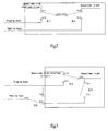
- Fig.2 is a schematic diagram showing the connection of relays in an analog subscriber board of one embodiment of the invention.
- each subscriber has a subscriber line interface circuit 1 and a subscriber line 4 for each subscriber solely, and a common ring bus 2 and a common test bus 3 in one subscriber group. Moreover, each subscriber has two relays K1 and K2. Other parts irrelevant directly to the technology of the invention are not shown in the drawing.
- subscriber line interface circuit 1 is connected to movable contact point K11 of relay K1
- ring bus 2 is connected to another movable contact point K12 of relay K1.
- Test bus 3 is connected to movable contact point K42 of relay K4
- subscriber line 4 is connected to another movable contact point K41 of relay K4.
- Static contact point K13 of relay K1 is connected to static contact point K43 of relay K4.
- Fig.2 for simplification, only one subscriber is shown in the connection schematic diagram.
- subscriber line interface circuit 1 and subscriber line 4 are for each subscriber solely, ring bus 2 and test bus 3 are common to all subscribers in one group.
- a plurality of analog voice functions can be provided by providing two relays K1, K4 for each subscriber respectively.
- Table 2 shows the realization of the various functions of the analog subscriber board.
- Various functions can be realized by controlling the states of two relays K1, K4 respectively.
- the analog subscriber board realizes correspondingly talking / idle function or ringing function respectively according to that relay K1 turns on movable contact point K11 connected to subscriber line interface circuit 1 or turns on movable contact point K12 connected to ring bus 2;
- relay K4 turns on movable contact point K42 connected to test bus 3 the analog subscriber board realizes correspondingly the function for testing the subscriber line interface circuit or the function for testing ring respectively according to that relay K1 turns on movable contact point K11 connected to subscriber line interface circuit 1 or turns
- the analog subscriber board can realize the functions of talking / idle, ringing, testing subscriber line interface circuit and testing ring by providing two relays for each subscriber.
- the monitoring function is not provided in above solution of line and relay in an analog subscriber board.
- the invention provides other solutions of line and relay in an analog subscriber board.
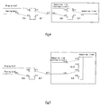
- Fig.3 is a schematic diagram showing the connection of relays and subscriber group relay in an analog subscriber board of another embodiment of the invention.
- each subscriber has two relays K1 and K5, moreover, each subscriber group has common relay K6. Other parts irrelevant directly to the technology of the invention are not shown in the drawing.
- subscriber line interface circuit 1 is connected to movable contact point K11 of relay K1
- ring bus 2 is connected to another movable contact point K12 of relay K1 and movable contact point K62 of relay K6 simultaneously.
- Test bus 3 is connected to static contact point K63 of relay K6.
- Subscriber line 4 is connected to static contact point K13 of relay K1 and a contact point K51 of relay K5 simultaneously.
- Another contact point K52 of relay K5 is connected to another movable contact point K61 of relay K6.
- Table 3 shows the realization of the various functions of the analog subscriber board.
- Various functions can be realized by controlling the states of three relays K1, K5, K6 respectively.
- the analog subscriber board realizes the basic functions ( talking/idle or ringing ) or the monitoring functions ( monitoring talking or monitoring ringing ), wherein when relay K5 is off, the analog subscriber board realizes correspondingly the talking/idle function or ringing function respectively according to that relay K1 turns on movable contact point K11 or movable contact point K12; when relay K5 is on, the analog subscriber board
- the analog subscriber board When relay K6 is controlled to turn on movable contact point K62, the analog subscriber board realizes the ring testing function or the ringing monitoring function, wherein when relay K1 turns on movable contact point K11, the analog subscriber board realizes the ring testing function; when relay K1 turns on movable contact point K12, the analog subscriber board realizes the ringing monitoring function.
- the talking/idle function can also be realized while ring testing function being realized.
- the analog subscriber board can realize the functions of talking/idle, ringing, monitoring talking, monitoring ringing and testing ring by providing two relays for each subscriber and a common relay in a subscriber group.
- Fig.4 is a schematic diagram showing the connection of relays and subscriber group relays in an analog subscriber board of a further embodiment of the invention.
- each subscriber has two relays K8 and K9, moreover, each subscriber group has two common relays K6 and K7. Other parts irrelevant directly to the technology of the invention are not shown in the drawing.
- subscriber line interface circuit 1 is connected to movable contact point K82 of relay K8 and movable contact point K91 of relay K9 simultaneously, ring bus 2 is connected to movable contact point K62 of relay K6 and movable contact point K71 of relay K7 simultaneously.
- Test bus 3 is connected to static contact point K63 of relay K6.
- Subscriber line 4 is connected to static contact point K93 of relay K9.
- Another movable contact point K61 of relay K6 is connected to another movable contact point K72 of relay K7.
- Static contact point K73 of relay K7 is connected to static contact point K83 of relay K8.
- Another movable contact point K81 of relay K8 is connected to another movable contact point K92 of relay K9.
- Table 4 shows the realization of the various functions of the analog subscriber board. Various functions can be realized by controlling the states of two common relays K6, K7 and two subscriber relays K8, K9 respectively. Realization of Various Functions of Analog Subscriber Board in Fig.4 State of K9 State of K8 State of K6 State of K7 Functions K91 K81 K61 ----- talking/idle K91 K81 K62 ----- talking/idle, testing ring K92 K81 K61 K71 ringing K92 K81 K61 K72 testing subscriber line K92 K81 K62 K71 monitoring ringing K92 K81 K62 K72 testing ring, talking/idle K91 K82 K61 K72 monitoring talking K92 K82 K61 K72 testing subscriber line interface circuit K92 K82 K62 K72 testing ring
- Fig.5 is a variation of the analog subscriber board in Fig.4.
- each subscriber there are subscriber line interface circuit 1 and subscriber line 4 for each subscriber solely, and common ring bus 2 and common test bus 3 in one subscriber group.
- Each subscriber has two relays K8 and K10, moreover, each subscriber group has two common relays K6 and K7.
- Other parts irrelevant directly to the technology of the invention are not shown in the drawing.
- subscriber line 4 is connected to movable contact point K82 of relay K8 and movable contact point K101 of relay K10 simultaneously.
- Ring bus 2 is connected to movable contact point K62 of relay K6 and movable contact point K71 of relay K7 simultaneously.
- Test bus 3 is connected to static contact point K63 of relay K6.
- Subscriber line interface circuit 1 is connected to static contact point K103 of relay K10.
- Another movable contact point K61 of relay K6 is connected to another movable contact point K72 of relay K7.
- Static contact point K73 of relay K7 is connected to static contact point K83 of relay K8.
- Another movable contact point K81 of relay K8 is connected to another movable contact point K102 of relay K10.
- Table 5 shows the realization of the various functions of the analog subscriber board. Various functions can be realized by controlling the states of two common relays K6, K7 and two subscriber relays K8, K10 respectively. Realization of Various Functions of Analog Subscriber Board in Fig.5 State of K10 State of K8 State of K6 State of K7 Functions K101 K81 K61 ----- talking/idle K101 K81 K62 ----- talking/idle, testing ring K102 K82 K61 K71 ringing K102 K82 K61 K72 testing subscriber line K102 K82 K62 K71 monitoring ringing K102 K82 K62 K72 testing ring, talking/idle K101 K82 K61 K72 monitoring talking K102 K81 K61 K72 testing subscriber line interface circuit K102 K81 K62 K72 testing ring
- Other states not shown in table 5 are unallowable states.
- the analog subscriber board can realize all of the functions of talking/idle, ringing, monitoring talking, monitoring ringing, testing subscriber line, testing subscriber line interface circuit and testing ring by providing two relays for each subscriber and two common relays in a subscriber group.
- Fig.6 is a schematic diagram showing the connection of relays and subscriber group relays in an analog subscriber board of a still further embodiment of the invention.
- each subscriber has two relays K1 and K4, moreover, each subscriber group has two common relays KC and KG. Other parts irrelevant directly to the technology of the invention are not shown in the drawing.
- subscriber line interface circuit 1 is connected to movable contact point K11 of relay K1, ring bus 2 is connected to contact point KC1 of relay KC.
- Test bus 3 is connected to movable contact point KG2 of relay KG and movable contact point K42 of relay K4 simultaneously, subscriber line 4 is connected to another movable contact point K41 of relay K4.
- Static contact point K13 of relay K1 is connected to static contact point K43 of relay K4.
- Another movable contact point K12 of relay K1 is connected to static contact point KG3 of relay KG.
- Another movable contact point KG1 of relay KG is connected to another contact point KC2 of relay KC.
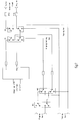
- Fig.7 is a diagram showing the actual connecting principle of the embodiment in Fig.6.
- Table 6 shows the realization of the various functions of the analog subscriber board.
- Various functions can be realized by controlling the states of two common relays KC, KG and two subscriber relays K1, K4 respectively.
- the analog subscriber board can realize the functions of talking/idle, ringing, testing subscriber line, testing subscriber line interface circuit and testing ring by providing two relays for each subscriber and two common relays in a subscriber group. Although the analog monitoring function is lost, it can be supplemented with digital monitoring, so that all functions can be realized.
- the idle subscriber line can be separated from the whole voice system, so that the influence on other lines resulting from interferences and abnormal signals can be avoided, and the errors can be reduced.
- ring bus 2 can be separated from the subscriber group by controlling KC to be off, so that the power consumption of the ring bus can be decreased.
- ring bus 2 test bus 3
- subscriber line interface circuit 1 subscriber line 4
- ring bus 2 test bus 3
- subscriber line interface circuit 1 subscriber line 4
- Fig.7 all lines must be constituted of double-lines, as shown in Fig.7.
- every relay must be changed from single-line relay to double-line relay.
- Fig.7 is a diagram with double-lines showing the actual connecting principle of the relays and the subscriber group relays in an analog subscriber board in Fig.6. It can be seen in Fig.7 that every line in Fig.6 is replaced with double-line and the relays with single-line are changed correspondingly to the relays with double-line, wherein it is well known in this field that the subscriber line interface circuit and the subscriber line are constituted of the pair of TIP / RING with double-line, and their TIPs / RINGs correspond with each other when the pair of TIP / RING with double-line are connected.
- the technical solution of the invention provides each subscriber with two relays to connect the subscriber line interface circuit, the subscriber line, the ring bus and the test bus, realizing the basic functions relevant to the talking, such as talking, ringing, etc.
- the auxiliary functions such as the testing function and the monitoring function
- at least one relay can be supplemented in a subscriber group, the subscriber group relays together with above two subscriber relays will be used to connect the subscriber line interface circuit, the subscriber line, the ring bus and the test bus to perform the basic functions relevant to talking and the auxiliary functions such as testing, monitoring, etc.
- the number of whole relays in the analog subscriber board of the invention is reduced, so that the whole cost of the subscriber board is decreased.
- the relays relevant to the auxiliary functions of the analog subscriber board of the prior art are provided in the subscriber, so that the number of whole relays provided must be increased.
- Two subscriber relays and the subscriber group relays of the invention can be connected to the subscriber line interface circuit, the subscriber line, the ring bus and the test bus in various ways, as shown in Fig.2 ⁇ 6, and above-mentioned embodiments are not intended to exhaust all aspects of the invention. Therefore, these specific connection ways should not be considered as the limitation to the invention, and the present invention will be defined by the appendant claims.
Landscapes
- Engineering & Computer Science (AREA)
- Signal Processing (AREA)
- Monitoring And Testing Of Exchanges (AREA)
- Interface Circuits In Exchanges (AREA)
- Electrochromic Elements, Electrophoresis, Or Variable Reflection Or Absorption Elements (AREA)
- Exchange Systems With Centralized Control (AREA)
- Molds, Cores, And Manufacturing Methods Thereof (AREA)
- Devices For Supply Of Signal Current (AREA)
Abstract
Description
| Realization of Various Functions of Analog Subscriber Board in Fig.1 | |||
| State of K1 | State of K2 | State of K3 | Function |
| K11 | K21 | K31 | talking/idle |
| K12 | K21 | K31 | ringing |
| K11 | K21 | K32 | monitoring talking |
| K12 | K21 | K32 | monitoring ringing |
| K11 | K22 | K31 | testing subscriber line interface circuit |
| K12 | K22 | K31 | testing ring |
| ----- | K22 | K32 | testing subscriber line |
| Realization of Various Functions of Analog Subscriber Board of One Embodiment of the Invention | ||
| State of K1 | State of K4 | Functions |
| K11 | K41 | talking / idle |
| K12 | K41 | ringing |
| K11 | K42 | testing subscriber |
| line interface circuit | ||
| K12 | K42 | testing ring |
| Realization of Various Functions of Analog Subscriber Board in Fig.3 | |||
| State of K1 | State of K6 | State of K5 | Functions |
| K11 | K61 | off | talking/idle |
| K12 | K61 | off | ringing |
| K11 | K61 | on | monitoring talking |
| K12 | K61 | on | monitoring ringing |
| K11 | K62 | ------ | testing ring, talking/idle |
| K12 | K62 | ------ | monitoring ringing |
| Realization of Various Functions of Analog Subscriber Board in Fig.4 | ||||
| State of K9 | State of K8 | State of K6 | State of K7 | Functions |
| K91 | K81 | K61 | ----- | talking/idle |
| K91 | K81 | K62 | ----- | talking/idle, testing ring |
| K92 | K81 | K61 | K71 | ringing |
| K92 | K81 | K61 | K72 | testing subscriber line |
| K92 | K81 | K62 | K71 | monitoring ringing |
| K92 | K81 | K62 | K72 | testing ring, talking/idle |
| K91 | K82 | K61 | K72 | monitoring talking |
| K92 | K82 | K61 | K72 | testing subscriber line interface circuit |
| K92 | K82 | K62 | K72 | testing ring |
| Realization of Various Functions of Analog Subscriber Board in Fig.5 | ||||
| State of K10 | State of K8 | State of K6 | State of K7 | Functions |
| K101 | K81 | K61 | ----- | talking/idle |
| K101 | K81 | K62 | ----- | talking/idle, testing ring |
| K102 | K82 | K61 | K71 | ringing |
| K102 | K82 | K61 | K72 | testing subscriber line |
| K102 | K82 | K62 | K71 | monitoring ringing |
| K102 | K82 | K62 | K72 | testing ring, talking/idle |
| K101 | K82 | K61 | K72 | monitoring talking |
| K102 | K81 | K61 | K72 | testing subscriber line interface circuit |
| K102 | K81 | K62 | K72 | testing ring |
| Realization of Various Functions of Analog Subscriber Board in Fig.6 | ||||
| State of K1 | State of K4 | State of KC | State of KG | Function |
| K11 | K41 | ----- | ----- | talking/idle |
| K12 | K41 | on | KG1 | ringing |
| K12 | ----- | off | KG1 | separating connection |
| K12 | K41 | ----- | KG2 | testing subscriber line |
| K12 | K42 | ----- | KG2 | separating connection |
| K12 | K42 | on | KG1 | testing ring |
| K11 | K42 | ----- | ----- | testing subscriber line interface circuit |
Claims (8)
- An analog subscriber board used in a voice network, comprising a subscriber line interface circuit and subscriber line for each subscriber and common ring bus and a test bus in a subscriber group, wherein said subscriber line interface circuit, subscriber line, ring bus and test bus are connected at least through the first relay and the second relay.
- The analog subscriber board according to claim 1, wherein:the subscriber line interface circuit is connected to a movable contact point of a first relay, the ring bus is connected to another movable contact point of the first relay;the test bus is connected to a movable contact point of a second relay, the subscriber line is connected to another movable contact point of the second relay; anda static contact point of the first relay is connected to a static contact point of the second relay.
- The analog subscriber board according to claim 1,
wherein said subscriber line interface circuit, subscriber line, ring bus and test bus are connected further through a first common relay in the subscriber group. - The analog subscriber board according to claim 3, wherein:the subscriber line interface circuit is connected to a movable contact point of the first subscriber relay;the ring bus is connected to another movable contact point of the first relay and a movable contact point of the first common relay simultaneously;the test bus is connected to a static contact point of the first common relay;the subscriber line is connected to a static contact point of the first relay and a contact point of the second relay; andanother contact point of the second relay is connected to another movable contact point of the first common relay.
- The analog subscriber board according to claim 3, wherein:said subscriber line interface circuit, subscriber line, ring bus and test bus are connected further through a second common relay in the subscriber group.
- The analog subscriber board according to claim 5, wherein:the subscriber line interface circuit is connected to a movable contact point of the first relay and a movable contact point of the second relay simultaneously;the ring bus is connected to a movable contact point of the first common relay and a movable contact point of the second common relay simultaneously;the test bus is connected to a static contact point of the first common relay;the subscriber line is connected to a static contact point of the second relay;another movable contact point of the first common relay is connected to another movable contact point of the second common relay; a static contact point of the second common relay is connected to a static contact point of the first relay; and another movable contact point of the first relay is connected to another movable contact point of the second relay.
- The analog subscriber board according to claim 5, wherein:the subscriber line is connected to a movable contact point of the first relay and a movable contact point of the second relay simultaneously;the ring bus is connected to a movable contact point of the first common relay and a movable contact point of the second common relay simultaneously;the test bus is connected to a static contact point of the first common relay;the subscriber line interface circuit is connected to a static contact point of the second relay;another movable contact point of the first common relay is connected to another movable contact point of the second common relay; a static contact point of the second common relay is connected to a static contact point of the first relay; and another movable contact point of the first relay is connected to another movable contact point of the second relay.
- The analog subscriber board according to claim 5, wherein:the subscriber line interface circuit is connected to a movable contact point of the first relay;the ring bus is connected to a contact point of the first common relay;the test bus is connected to a movable contact point of the second common relay and a movable contact point of the second relay simultaneously;the subscriber line is connected to another movable contact point of the second relay; anda static contact point of the first relay is connected to a static contact point of the second relay; another movable contact point of the first relay is connected to a static contact point of the second common relay; and another movable contact point of the second common relay is connected to another contact point of the first common relay.
Applications Claiming Priority (2)
| Application Number | Priority Date | Filing Date | Title |
|---|---|---|---|
| CN200310122996A CN100591082C (en) | 2003-12-30 | 2003-12-30 | Analog user board |
| CN200310122996 | 2003-12-30 |
Publications (2)
| Publication Number | Publication Date |
|---|---|
| EP1551161A1 true EP1551161A1 (en) | 2005-07-06 |
| EP1551161B1 EP1551161B1 (en) | 2007-09-05 |
Family
ID=34558476
Family Applications (1)
| Application Number | Title | Priority Date | Filing Date |
|---|---|---|---|
| EP04027367A Expired - Lifetime EP1551161B1 (en) | 2003-12-30 | 2004-11-18 | Analog subscriber board |
Country Status (5)
| Country | Link |
|---|---|
| US (1) | US7769140B2 (en) |
| EP (1) | EP1551161B1 (en) |
| CN (1) | CN100591082C (en) |
| AT (1) | ATE372642T1 (en) |
| DE (1) | DE602004008732D1 (en) |
Citations (4)
| Publication number | Priority date | Publication date | Assignee | Title |
|---|---|---|---|---|
| US4445007A (en) * | 1981-03-18 | 1984-04-24 | Telecommunications Radioelectriquest Et Telephoniques T.R.T. | Remote testing of subscriber line interface circuits |
| EP0386369A2 (en) * | 1989-03-09 | 1990-09-12 | Gpt Limited | Apparatus for testing and sparing linecard equipment in a telecommunications exchange |
| US5367567A (en) * | 1991-05-07 | 1994-11-22 | Fujitsu Limited | Subscriber apparatus with ringer generator for sending ringer signal to subscriber line |
| DE19627937A1 (en) * | 1996-07-11 | 1998-01-15 | Bosch Gmbh Robert | Telecommunication system subscriber circuit |
Family Cites Families (6)
| Publication number | Priority date | Publication date | Assignee | Title |
|---|---|---|---|---|
| FR2555388B1 (en) * | 1983-11-23 | 1986-02-21 | Cit Alcatel | BACKUP DEVICE OF A SUBSCRIBER TERMINAL IN A DIGITAL CONCENTRATOR |
| US5195125A (en) * | 1990-09-17 | 1993-03-16 | Raychem Corporation | Gel filled RJ11 connector |
| JP3056551B2 (en) * | 1991-09-02 | 2000-06-26 | 富士通株式会社 | Alerting cadence control method for subscriber transmission equipment. |
| US5323460A (en) * | 1992-01-07 | 1994-06-21 | Ag Communication Systems Corporation | Enhanced subscriber line interface circuit |
| US6490277B1 (en) * | 2001-06-04 | 2002-12-03 | Adc Telecommunications, Inc. | Digital cross-connect system employing patch access locking and redundant supply power |
| US20060256931A1 (en) * | 2002-03-11 | 2006-11-16 | Udo Bendig | Contact bank measurement arrangement including a contact bank telecommunications module provided with contact bank or a measurement arrangement and telecommunications assembly including plural modules |
-
2003
- 2003-12-30 CN CN200310122996A patent/CN100591082C/en not_active Expired - Lifetime
-
2004
- 2004-11-18 DE DE602004008732T patent/DE602004008732D1/en not_active Expired - Lifetime
- 2004-11-18 EP EP04027367A patent/EP1551161B1/en not_active Expired - Lifetime
- 2004-11-18 AT AT04027367T patent/ATE372642T1/en not_active IP Right Cessation
- 2004-12-03 US US11/002,253 patent/US7769140B2/en not_active Expired - Fee Related
Patent Citations (4)
| Publication number | Priority date | Publication date | Assignee | Title |
|---|---|---|---|---|
| US4445007A (en) * | 1981-03-18 | 1984-04-24 | Telecommunications Radioelectriquest Et Telephoniques T.R.T. | Remote testing of subscriber line interface circuits |
| EP0386369A2 (en) * | 1989-03-09 | 1990-09-12 | Gpt Limited | Apparatus for testing and sparing linecard equipment in a telecommunications exchange |
| US5367567A (en) * | 1991-05-07 | 1994-11-22 | Fujitsu Limited | Subscriber apparatus with ringer generator for sending ringer signal to subscriber line |
| DE19627937A1 (en) * | 1996-07-11 | 1998-01-15 | Bosch Gmbh Robert | Telecommunication system subscriber circuit |
Also Published As
| Publication number | Publication date |
|---|---|
| US7769140B2 (en) | 2010-08-03 |
| CN100591082C (en) | 2010-02-17 |
| EP1551161B1 (en) | 2007-09-05 |
| ATE372642T1 (en) | 2007-09-15 |
| DE602004008732D1 (en) | 2007-10-18 |
| US20050152532A1 (en) | 2005-07-14 |
| CN1635769A (en) | 2005-07-06 |
Similar Documents
| Publication | Publication Date | Title |
|---|---|---|
| KR970064299A (en) | Cordless phone system | |
| EP1551161A1 (en) | Analog subscriber board | |
| CN201039271Y (en) | Business board and test system | |
| CN101867662B (en) | High-impedance monitoring device and method for user call | |
| CN113015037A (en) | Multi-person talkback MNC network networking technology | |
| US7783033B2 (en) | Network breaker | |
| CN104113647A (en) | Anti-interference conference telephone | |
| CN206865557U (en) | The integrated dispatching desk that one kind of multiple standards access simultaneously | |
| US20020091508A1 (en) | Emulating exchange for multiple servers | |
| JPS61145947A (en) | Ring trip circuit | |
| JPH03224395A (en) | Key telephone system | |
| CN101335536A (en) | Electronic device for reducing audio noise generated by ground imbalance and communication device thereof | |
| RU2017342C1 (en) | Party-line communication system | |
| KR0162613B1 (en) | Extension Telephone Signal Test Method | |
| CN117880417A (en) | Military voice communication detection system and detection method thereof | |
| JPS6298954A (en) | Line inspecting instrument | |
| JPS60251753A (en) | Call waiting method | |
| JPS62137950A (en) | Telephone set | |
| JPH056948B2 (en) | ||
| Davidson | Toll switchboard no. 3 | |
| GB2333203A (en) | Telephone testing handset | |
| JPH01179596A (en) | button telephone device | |
| JPS6133062A (en) | Automatic dial telephone set | |
| JP2002077375A (en) | Receiving method of cordless telephone system with multiple handsets | |
| JPS634758A (en) | Ordering telephone system |
Legal Events
| Date | Code | Title | Description |
|---|---|---|---|
| PUAI | Public reference made under article 153(3) epc to a published international application that has entered the european phase |
Free format text: ORIGINAL CODE: 0009012 |
|
| AK | Designated contracting states |
Kind code of ref document: A1 Designated state(s): AT BE BG CH CY CZ DE DK EE ES FI FR GB GR HU IE IS IT LI LU MC NL PL PT RO SE SI SK TR |
|
| AX | Request for extension of the european patent |
Extension state: AL HR LT LV MK YU |
|
| 17P | Request for examination filed |
Effective date: 20060109 |
|
| AKX | Designation fees paid |
Designated state(s): AT BE BG CH CY CZ DE DK EE ES FI FR GB GR HU IE IS IT LI LU MC NL PL PT RO SE SI SK TR |
|
| GRAP | Despatch of communication of intention to grant a patent |
Free format text: ORIGINAL CODE: EPIDOSNIGR1 |
|
| RAP1 | Party data changed (applicant data changed or rights of an application transferred) |
Owner name: ALCATEL LUCENT |
|
| GRAS | Grant fee paid |
Free format text: ORIGINAL CODE: EPIDOSNIGR3 |
|
| GRAA | (expected) grant |
Free format text: ORIGINAL CODE: 0009210 |
|
| AK | Designated contracting states |
Kind code of ref document: B1 Designated state(s): AT BE BG CH CY CZ DE DK EE ES FI FR GB GR HU IE IS IT LI LU MC NL PL PT RO SE SI SK TR |
|
| REG | Reference to a national code |
Ref country code: GB Ref legal event code: FG4D |
|
| REG | Reference to a national code |
Ref country code: CH Ref legal event code: EP |
|
| REF | Corresponds to: |
Ref document number: 602004008732 Country of ref document: DE Date of ref document: 20071018 Kind code of ref document: P |
|
| REG | Reference to a national code |
Ref country code: IE Ref legal event code: FG4D |
|
| PG25 | Lapsed in a contracting state [announced via postgrant information from national office to epo] |
Ref country code: ES Free format text: LAPSE BECAUSE OF FAILURE TO SUBMIT A TRANSLATION OF THE DESCRIPTION OR TO PAY THE FEE WITHIN THE PRESCRIBED TIME-LIMIT Effective date: 20071216 Ref country code: FI Free format text: LAPSE BECAUSE OF FAILURE TO SUBMIT A TRANSLATION OF THE DESCRIPTION OR TO PAY THE FEE WITHIN THE PRESCRIBED TIME-LIMIT Effective date: 20070905 |
|
| PG25 | Lapsed in a contracting state [announced via postgrant information from national office to epo] |
Ref country code: LI Free format text: LAPSE BECAUSE OF FAILURE TO SUBMIT A TRANSLATION OF THE DESCRIPTION OR TO PAY THE FEE WITHIN THE PRESCRIBED TIME-LIMIT Effective date: 20070905 Ref country code: AT Free format text: LAPSE BECAUSE OF FAILURE TO SUBMIT A TRANSLATION OF THE DESCRIPTION OR TO PAY THE FEE WITHIN THE PRESCRIBED TIME-LIMIT Effective date: 20070905 Ref country code: CH Free format text: LAPSE BECAUSE OF FAILURE TO SUBMIT A TRANSLATION OF THE DESCRIPTION OR TO PAY THE FEE WITHIN THE PRESCRIBED TIME-LIMIT Effective date: 20070905 Ref country code: PL Free format text: LAPSE BECAUSE OF FAILURE TO SUBMIT A TRANSLATION OF THE DESCRIPTION OR TO PAY THE FEE WITHIN THE PRESCRIBED TIME-LIMIT Effective date: 20070905 |
|
| NLV1 | Nl: lapsed or annulled due to failure to fulfill the requirements of art. 29p and 29m of the patents act | ||
| PG25 | Lapsed in a contracting state [announced via postgrant information from national office to epo] |
Ref country code: BE Free format text: LAPSE BECAUSE OF FAILURE TO SUBMIT A TRANSLATION OF THE DESCRIPTION OR TO PAY THE FEE WITHIN THE PRESCRIBED TIME-LIMIT Effective date: 20070905 |
|
| REG | Reference to a national code |
Ref country code: CH Ref legal event code: PL |
|
| PG25 | Lapsed in a contracting state [announced via postgrant information from national office to epo] |
Ref country code: GR Free format text: LAPSE BECAUSE OF FAILURE TO SUBMIT A TRANSLATION OF THE DESCRIPTION OR TO PAY THE FEE WITHIN THE PRESCRIBED TIME-LIMIT Effective date: 20071206 Ref country code: NL Free format text: LAPSE BECAUSE OF FAILURE TO SUBMIT A TRANSLATION OF THE DESCRIPTION OR TO PAY THE FEE WITHIN THE PRESCRIBED TIME-LIMIT Effective date: 20070905 |
|
| EN | Fr: translation not filed | ||
| PG25 | Lapsed in a contracting state [announced via postgrant information from national office to epo] |
Ref country code: SK Free format text: LAPSE BECAUSE OF FAILURE TO SUBMIT A TRANSLATION OF THE DESCRIPTION OR TO PAY THE FEE WITHIN THE PRESCRIBED TIME-LIMIT Effective date: 20070905 Ref country code: IS Free format text: LAPSE BECAUSE OF FAILURE TO SUBMIT A TRANSLATION OF THE DESCRIPTION OR TO PAY THE FEE WITHIN THE PRESCRIBED TIME-LIMIT Effective date: 20080105 Ref country code: PT Free format text: LAPSE BECAUSE OF FAILURE TO SUBMIT A TRANSLATION OF THE DESCRIPTION OR TO PAY THE FEE WITHIN THE PRESCRIBED TIME-LIMIT Effective date: 20080206 Ref country code: CZ Free format text: LAPSE BECAUSE OF FAILURE TO SUBMIT A TRANSLATION OF THE DESCRIPTION OR TO PAY THE FEE WITHIN THE PRESCRIBED TIME-LIMIT Effective date: 20070905 |
|
| PG25 | Lapsed in a contracting state [announced via postgrant information from national office to epo] |
Ref country code: MC Free format text: LAPSE BECAUSE OF NON-PAYMENT OF DUE FEES Effective date: 20071130 Ref country code: RO Free format text: LAPSE BECAUSE OF FAILURE TO SUBMIT A TRANSLATION OF THE DESCRIPTION OR TO PAY THE FEE WITHIN THE PRESCRIBED TIME-LIMIT Effective date: 20070905 Ref country code: SE Free format text: LAPSE BECAUSE OF FAILURE TO SUBMIT A TRANSLATION OF THE DESCRIPTION OR TO PAY THE FEE WITHIN THE PRESCRIBED TIME-LIMIT Effective date: 20071205 |
|
| PLBE | No opposition filed within time limit |
Free format text: ORIGINAL CODE: 0009261 |
|
| STAA | Information on the status of an ep patent application or granted ep patent |
Free format text: STATUS: NO OPPOSITION FILED WITHIN TIME LIMIT |
|
| PG25 | Lapsed in a contracting state [announced via postgrant information from national office to epo] |
Ref country code: DE Free format text: LAPSE BECAUSE OF FAILURE TO SUBMIT A TRANSLATION OF THE DESCRIPTION OR TO PAY THE FEE WITHIN THE PRESCRIBED TIME-LIMIT Effective date: 20071206 Ref country code: DK Free format text: LAPSE BECAUSE OF FAILURE TO SUBMIT A TRANSLATION OF THE DESCRIPTION OR TO PAY THE FEE WITHIN THE PRESCRIBED TIME-LIMIT Effective date: 20070905 |
|
| 26N | No opposition filed |
Effective date: 20080606 |
|
| PG25 | Lapsed in a contracting state [announced via postgrant information from national office to epo] |
Ref country code: FR Free format text: LAPSE BECAUSE OF FAILURE TO SUBMIT A TRANSLATION OF THE DESCRIPTION OR TO PAY THE FEE WITHIN THE PRESCRIBED TIME-LIMIT Effective date: 20080502 |
|
| PG25 | Lapsed in a contracting state [announced via postgrant information from national office to epo] |
Ref country code: IE Free format text: LAPSE BECAUSE OF NON-PAYMENT OF DUE FEES Effective date: 20071119 |
|
| PG25 | Lapsed in a contracting state [announced via postgrant information from national office to epo] |
Ref country code: EE Free format text: LAPSE BECAUSE OF FAILURE TO SUBMIT A TRANSLATION OF THE DESCRIPTION OR TO PAY THE FEE WITHIN THE PRESCRIBED TIME-LIMIT Effective date: 20070905 |
|
| PG25 | Lapsed in a contracting state [announced via postgrant information from national office to epo] |
Ref country code: SI Free format text: LAPSE BECAUSE OF FAILURE TO SUBMIT A TRANSLATION OF THE DESCRIPTION OR TO PAY THE FEE WITHIN THE PRESCRIBED TIME-LIMIT Effective date: 20070905 |
|
| PG25 | Lapsed in a contracting state [announced via postgrant information from national office to epo] |
Ref country code: CY Free format text: LAPSE BECAUSE OF FAILURE TO SUBMIT A TRANSLATION OF THE DESCRIPTION OR TO PAY THE FEE WITHIN THE PRESCRIBED TIME-LIMIT Effective date: 20070905 |
|
| PG25 | Lapsed in a contracting state [announced via postgrant information from national office to epo] |
Ref country code: BG Free format text: LAPSE BECAUSE OF FAILURE TO SUBMIT A TRANSLATION OF THE DESCRIPTION OR TO PAY THE FEE WITHIN THE PRESCRIBED TIME-LIMIT Effective date: 20071205 Ref country code: LU Free format text: LAPSE BECAUSE OF NON-PAYMENT OF DUE FEES Effective date: 20071118 |
|
| PG25 | Lapsed in a contracting state [announced via postgrant information from national office to epo] |
Ref country code: TR Free format text: LAPSE BECAUSE OF FAILURE TO SUBMIT A TRANSLATION OF THE DESCRIPTION OR TO PAY THE FEE WITHIN THE PRESCRIBED TIME-LIMIT Effective date: 20070905 Ref country code: HU Free format text: LAPSE BECAUSE OF FAILURE TO SUBMIT A TRANSLATION OF THE DESCRIPTION OR TO PAY THE FEE WITHIN THE PRESCRIBED TIME-LIMIT Effective date: 20080306 |
|
| PG25 | Lapsed in a contracting state [announced via postgrant information from national office to epo] |
Ref country code: IT Free format text: LAPSE BECAUSE OF NON-PAYMENT OF DUE FEES Effective date: 20071130 |
|
| REG | Reference to a national code |
Ref country code: FR Ref legal event code: CA Effective date: 20150521 |
|
| REG | Reference to a national code |
Ref country code: FR Ref legal event code: CA Effective date: 20150521 |
|
| PGFP | Annual fee paid to national office [announced via postgrant information from national office to epo] |
Ref country code: GB Payment date: 20181114 Year of fee payment: 15 |
|
| GBPC | Gb: european patent ceased through non-payment of renewal fee |
Effective date: 20191118 |
|
| PG25 | Lapsed in a contracting state [announced via postgrant information from national office to epo] |
Ref country code: GB Free format text: LAPSE BECAUSE OF NON-PAYMENT OF DUE FEES Effective date: 20191118 |