EP1551114A1 - Adaptive array radio communication apparatus, reception level displaying method, reception level adjusting method, reception level displaying program, and reception level adjusting program - Google Patents
Adaptive array radio communication apparatus, reception level displaying method, reception level adjusting method, reception level displaying program, and reception level adjusting program Download PDFInfo
- Publication number
- EP1551114A1 EP1551114A1 EP03797540A EP03797540A EP1551114A1 EP 1551114 A1 EP1551114 A1 EP 1551114A1 EP 03797540 A EP03797540 A EP 03797540A EP 03797540 A EP03797540 A EP 03797540A EP 1551114 A1 EP1551114 A1 EP 1551114A1
- Authority
- EP
- European Patent Office
- Prior art keywords
- reception level
- reception
- signals
- antennas
- display
- Prior art date
- Legal status (The legal status is an assumption and is not a legal conclusion. Google has not performed a legal analysis and makes no representation as to the accuracy of the status listed.)
- Withdrawn
Links
Images



Classifications
-
- H—ELECTRICITY
- H01—ELECTRIC ELEMENTS
- H01Q—ANTENNAS, i.e. RADIO AERIALS
- H01Q3/00—Arrangements for changing or varying the orientation or the shape of the directional pattern of the waves radiated from an antenna or antenna system
- H01Q3/26—Arrangements for changing or varying the orientation or the shape of the directional pattern of the waves radiated from an antenna or antenna system varying the relative phase or relative amplitude of energisation between two or more active radiating elements; varying the distribution of energy across a radiating aperture
-
- H—ELECTRICITY
- H01—ELECTRIC ELEMENTS
- H01Q—ANTENNAS, i.e. RADIO AERIALS
- H01Q3/00—Arrangements for changing or varying the orientation or the shape of the directional pattern of the waves radiated from an antenna or antenna system
- H01Q3/26—Arrangements for changing or varying the orientation or the shape of the directional pattern of the waves radiated from an antenna or antenna system varying the relative phase or relative amplitude of energisation between two or more active radiating elements; varying the distribution of energy across a radiating aperture
- H01Q3/30—Arrangements for changing or varying the orientation or the shape of the directional pattern of the waves radiated from an antenna or antenna system varying the relative phase or relative amplitude of energisation between two or more active radiating elements; varying the distribution of energy across a radiating aperture varying the relative phase between the radiating elements of an array
-
- H—ELECTRICITY
- H04—ELECTRIC COMMUNICATION TECHNIQUE
- H04B—TRANSMISSION
- H04B17/00—Monitoring; Testing
- H04B17/20—Monitoring; Testing of receivers
- H04B17/23—Indication means, e.g. displays, alarms, audible means
-
- H—ELECTRICITY
- H04—ELECTRIC COMMUNICATION TECHNIQUE
- H04B—TRANSMISSION
- H04B17/00—Monitoring; Testing
- H04B17/30—Monitoring; Testing of propagation channels
- H04B17/309—Measuring or estimating channel quality parameters
- H04B17/318—Received signal strength
-
- H—ELECTRICITY
- H04—ELECTRIC COMMUNICATION TECHNIQUE
- H04B—TRANSMISSION
- H04B7/00—Radio transmission systems, i.e. using radiation field
- H04B7/02—Diversity systems; Multi-antenna system, i.e. transmission or reception using multiple antennas
- H04B7/04—Diversity systems; Multi-antenna system, i.e. transmission or reception using multiple antennas using two or more spaced independent antennas
- H04B7/08—Diversity systems; Multi-antenna system, i.e. transmission or reception using multiple antennas using two or more spaced independent antennas at the receiving station
Definitions
- the present invention relates to an adaptive array wireless communication apparatus, a reception level display method, a reception level adjusting method, a reception level display program and a reception level adjusting program.
- the present invention relates to a mobile terminal apparatus having an adaptive array function using a plurality of antennas, and to a reception level display method, a reception level adjusting method, a reception level display program and a reception level adjusting program used in such a mobile terminal apparatus.
- a mobile communication system such as a PHS (Personal Handyphone System)
- wireless communication is established between a mobile terminal apparatus (hereinafter referred to as a terminal) and wireless base station (hereinafter referred to as a base station).
- a terminal mobile terminal apparatus
- a base station wireless base station
- a conventional terminal typically has one antenna, and a radio frequency (RF) signal received by the antenna is subjected to various signal processing including amplification and frequency conversion in an RF receiving circuit.
- RF radio frequency
- reception level a reception power level of the received signal.
- the reception level of the signal received by the antenna measured by the RF receiving circuit is displayed (notified) to the user on a display of the terminal, and hence, the user can estimate radio wave environment of the terminal.
- a diversity terminal having two antennas and corresponding RF receiving circuits and selecting one of the antennas that has higher reception level as a reception antenna has been realized and disclosed, for example, in Japanese Patent Laying-Open No. 8-97759.
- the diversity terminal has two antennas as mentioned above, and a received signal of one stream from either one of the antennas is selected, taken in the terminal and subjected to a signal processing for demodulation. Therefore, only the reception level of the received signal of one stream selected for demodulation is displayed for the user.
- an adaptive array base station has been practically implemented, at which a signal from a specific user is received by a plurality of antennas, and the received signals of the plurality of streams are subjected to well-known adaptive array processing, so that the received signal from the user is separated and extracted.
- the adaptive array processing refers to a well-known process in which based on received signals from terminals, a weight vector consisting of reception coefficients (weights) of respective ones of the plurality of antennas of the base station is estimated and adaptively controlled, so that a signal from a specific terminal can be extracted (synthesized) accurately.
- a weight vector consisting of reception coefficients (weights) of respective ones of the plurality of antennas of the base station is estimated and adaptively controlled, so that a signal from a specific terminal can be extracted (synthesized) accurately.
- an adaptive array terminal having the function of adaptive array processing has also been developed.
- Such an adaptive array terminal has a plurality of (for example, two) antennas and corresponding plurality of (two) RF receiving circuits, and signals of a plurality of streams received by respective antennas are taken into the terminal and subjected to the adaptive array processing.
- the reception level difference among the plurality of antennas is adjusted by some method, in order to improve reception performance of the adaptive array terminal.
- a terminal having two antennas as is the case of the diversity terminal described above, one of which is a fixed antenna provided inside the terminal and the other is a movable antenna mounted on the outside of the terminal of which angle can be adjusted by moving itself forward or backward, has been implemented as an example of the conventional terminals.
- the reception level display for the user is only the reception level of the signal of one stream received and taken in the terminal as described above, regardless of the number of antennas of the terminal.
- the conventional terminal having a plurality of (two) antennas employs a movable antenna allowing angle adjustment of the antenna, it has been impossible to know the reception level of each of the plurality of antennas.
- the reception level has been adjusted by the user manually adjusting the angle of the movable antenna while visually monitoring the reception level displayed on the terminal, which adjustment has been unsatisfactory in accuracy.
- an object of the present invention is to provide an adaptive array wireless communication apparatus, a reception level display method, a reception level adjusting method, a reception level display program and a reception level adjusting program, by which it becomes possible for the user to readily adjust the reception level of the antenna even in an adaptive array wireless communication apparatus having a plurality of antennas.
- Another object of the present invention is to provide an adaptive array wireless communication apparatus, a reception level display method, a reception level adjusting method, a reception level display program and a reception level adjusting program, by which the reception level of the antenna can automatically be adjusted with high accuracy even in an adaptive array wireless communication apparatus having a plurality of antennas.
- the present invention provides an adaptive array wireless communication apparatus having a plurality of antennas, including determining means, display means and reception level adjusting means.
- the determining means determines reception levels of signals of a plurality of streams received by respective ones of the plurality of antennas.
- the display means displays the determined reception levels of the signals of the plurality of streams.
- the reception level adjusting means allows, by manual operation by the user, adjustment of the reception levels of signals of the plurality of streams.
- the display means displays a numerical value indicative of the reception level of each of the signals of the plurality of streams.
- the display means displays a difference value between each of the reception levels of the signals of the plurality of streams.
- the display means displays a degree of magnitude of the difference value between each of the reception levels of the signals of the plurality of streams.
- the display means is capable of selectively displaying, as contents of display, any of numerical value indicative of the reception level of each of the signals of the plurality of streams, the difference value between each of the reception levels and a degree of magnitude of the difference value
- the adaptive array wireless communication apparatus further includes display contents determining means for determining the contents to be displayed by the displaying means, in accordance with prior designation by the user.
- the display means is capable of selectively displaying, as contents of display, any of numerical value indicative of the reception level of each of the signals of the plurality of streams, the difference value between each of the reception levels and a degree of magnitude of the difference value
- the adaptive array wireless communication apparatus further includes display contents switching means for periodically and successively switching the contents to be displayed by the display means.
- the adaptive array wireless communication apparatus further includes activating means for automatically activating the determining means and the display means.
- the adaptive array wireless communication apparatus further includes activating means for activating, in response to a user instruction, the determining means and the reception level adjusting means.
- the present invention provides an adaptive array wireless communication apparatus having a plurality of antennas including determining means, reception level difference calculating means, and reception level adjusting means.
- the determining means determines reception levels of signals of a plurality of streams received by respective ones of the plurality of antennas.
- the reception level difference calculating means calculates a difference among the determined reception levels of the signals of the plurality of streams.
- the reception level adjusting means adjusts the reception levels of signals of the plurality of streams such that the calculated reception level difference decreases.
- the reception level adjusting means includes antenna driving means for changing an angle between each of the plurality of antennas, and control means for controlling the antenna driving means such that the angle between each of the plurality of antennas is changed such that the reception level difference is not higher than a prescribed threshold value.
- the adaptive array wireless communication apparatus further includes activating means for automatically activating the determining means and the reception level adjusting means.
- the adaptive array wireless communication apparatus further includes activating means for activating, in response to a user instruction, the determining means and the reception level adjusting means.
- the present invention provides a method of displaying a reception level in an adaptive array wireless communication apparatus having a plurality of antennas, including the step of determining reception levels of signals of a plurality of streams received by respective ones of the plurality of antennas, and the step of displaying the determined reception levels of signals of the plurality of streams.
- a numerical value indicative of the reception level of each of the signals of the plurality of streams is displayed.
- a difference value between each of the reception levels of the signals of the plurality of streams is displayed.
- a degree of magnitude of the difference value between each of the reception levels of the signals of the plurality of streams is displayed.
- any of a numerical value indicative of the reception level of each of the signals of the plurality of streams, the difference value between each of the reception levels and a degree of magnitude of the difference value can selectively be displayed as the display contents
- the method of displaying the reception level further includes the step of determining the contents to be displayed in the display step in accordance with prior designation by the user.
- any of a numerical value indicative of the reception level of each of the signals of the plurality of streams, the difference value between each of the reception levels and a degree of magnitude of the difference value can selectively be displayed as the display contents, and the method of displaying the reception level further includes the step of periodically and successively switching the contents to be displayed in the display step.
- the method of displaying the reception level further includes the step of automatically activating the determining step and the display step.
- the method of displaying the reception level further includes the step of activating, in response to a user instruction, the determining step and the display step.
- the present invention provides a method of adjusting a reception level in an adaptive array wireless communication apparatus having a plurality of antennas including the step of determining reception levels of signals of a plurality of streams received by respective ones of the plurality of antennas, the step of calculating a difference among the determined reception levels of the signals of the plurality of streams, and the step of adjusting the reception levels of signals of the plurality of streams such that the calculated reception level difference decreases.
- the reception level adjusting step includes the step of changing an angle between each of the plurality of antennas such that the reception level difference is not higher than a prescribed threshold value.
- the method of adjusting reception level further includes the step of automatically activating the determining step and the reception level adjusting step.
- the method of adjusting reception level further includes the step of activating, in response to a user instruction, the determining step and the reception level adjusting step.
- the present invention provides a reception level display program in an adaptive array wireless communication apparatus having a plurality of antennas, causing a computer to execute the step of determining reception levels of signals of a plurality of streams received by respective ones of the plurality of antennas, and the display step of displaying the determined reception levels of signals of the plurality of streams.
- a numerical value indicative of the reception level of each of the signals of the plurality of streams is displayed.
- a difference value between each of the reception levels of the signals of the plurality of streams is displayed.
- a degree of magnitude of the difference value between each of the reception levels of the signals of the plurality of streams is displayed.
- any of a numerical value indicative of the reception level of each of the signals of the plurality of streams, the difference value between each of the reception levels and a degree of magnitude of the difference value can selectively be displayed as the display contents, and the reception level display program causes the computer to further execute the step of determining the contents to be displayed in the display step, in accordance with prior designation by the user.
- any of a numerical value indicative of the reception level of each of the signals of the plurality of streams, the difference value between each of the reception levels and the degree of magnitude of the difference value can selectively be displayed as the display contents, and the reception level display program causes the computer to further execute the step of periodically and successively switching the contents to be displayed in the display step.
- the reception level display program causes the computer to further execute the step of automatically activating the determining step and the display step.
- the program causes the computer to further execute the step of activating, in response to a user instruction, the determining step and the display step.
- the present invention provides a reception level adjusting program in an adaptive array wireless communication apparatus having a plurality of antennas, causing a computer to execute the step of determining reception levels of signals of a plurality of streams received by respective ones of the plurality of antennas, the step of calculating a difference value between each of the determined reception levels of the signals of the plurality of streams, and the step of adjusting the reception levels of signals of the plurality of streams such that the calculated reception level difference becomes smaller.
- the reception level adjusting step includes the step of changing an angle between each of the plurality of antennas such that the reception level difference is not higher than a prescribed threshold value.
- the reception level adjusting program causes the computer to further execute the step of automatically activating the determining step and the reception level adjusting step.
- the reception level adjusting program causes the computer to further execute the step of activating, in response to a user instruction, the determining step and the reception level adjusting step.
- the reception levels of signals of a plurality of streams received by respective ones of the plurality of antennas can be displayed to the user. Therefore, it becomes possible for the user to adjust reception level such that reception level difference among antennas decreases by adjusting, for example, an angle of a movable antenna while visually monitoring the display.
- the reception performance of adaptive array processing in the adaptive array wireless communication apparatus can further be improved.
- reception level difference of signals of the plurality of streams received by respective ones of the plurality of antennas is calculated, and by automatically adjusting an angle of a movable antenna, for example, to reduce the difference, the reception level can be adjusted with higher accuracy. Therefore, the reception performance of adaptive array processing in the adaptive array wireless communication apparatus can further be improved.
- Fig. 1 is a functional block diagram representing a configuration of an adaptive array terminal in accordance with a first embodiment of the present invention.
- each of RF receiving circuits 1 and 2 the received RF signal is subjected to prescribed analog processing such as amplification and frequency conversion, and the resulting signal is applied to a signal processing unit 3.
- signal processing unit 3 Under the control of a main control unit 5, signal processing unit 3 performs the adaptive array processing on the signals received from RF receiving circuits 1 and 2, whereby desired reception signals are separated and extracted.
- a well-known adaptive array processing is performed, in which based on the reception signals from the base station, a weight vector consisting of weights of two antennas ANT#1 and ANT#2 of the terminal is estimated and adaptively controlled, so that the desired signal from the base station is extracted (synthesized) accurately.
- the signal processing unit 3 shown in Fig. 1 includes a weight control unit, not shown, for estimating the weight vector for each symbol of the received signal, and the weight control unit executes a process of converging the weight vector such that a square of a difference between a complex multiplication sum of the received signal vector and the estimated weight vector and a known reference signal decreases, that is, the adaptive array processing of converging the reception directivity from the base station.
- such a convergence of weight vector is performed adaptively in accordance with time and variation of propagation path characteristics of signal waves, so that interference components and noise can be removed from the received signal and the signal from the base station can be extracted.
- sequential estimation algorithm such as RLS (Recursive Least Squares) algorithm or LMS (Least Mean Square) algorithm is used.
- a demodulating unit 4 shown in Fig. 1 performs, under the control by main control unit 5, a demodulating process on the received signal separated and extracted by the adaptive array processing at signal processing unit 3, and outputs demodulated bit outputs.
- Main control unit 5 controls operations of not only the signal processing unit 3 and demodulating unit 4 described above but also of a display unit 6, which will be described later, in accordance with an instruction by the user through an input unit 7.
- reception levels of the received signals are measured, and reception level 1 from RF receiving circuit 1 and reception level 2 from RF receiving circuit 2, respectively, are applied to main control unit 5.
- Main control unit 5 converts reception levels 1 and 2 received from RF receiving circuits 1 and 2 to various display formats, as will be described later, and displays on display unit 6 at a prescribed timing.
- Display unit 6 may be implemented by display devices of various types, such as light emitting diode (LED) and liquid crystal display (LCD).
- LED light emitting diode
- LCD liquid crystal display
- the reception level may be indicated by flickering or the color of light emission.
- the reception level may be indicated by characters or numerical values appearing on the display screen.
- Fig. 2 is a schematic diagram representing an exemplary method of displaying the reception level of the adaptive array terminal in accordance with a first embodiment of the present invention.
- FIG. 2 (a) schematically shows a frontal view of an adaptive array terminal 100.
- adaptive array terminal 100 has two antennas ANT#1 and ANT#2, at least one of which is a movable antenna that can be moved forward and backward, allowing adjustment of an angle with the other antenna.
- adaptive array terminal 100 has the display unit corresponding to display unit 6 of Fig. 1 implemented by an LED and/or LCD. In the following, the manner of displaying the reception level using these display units will be described.
- Fig. 2 (b) shows an exemplary Display Method 1 in accordance with the first embodiment of the present invention.
- Display Method 1 reception levels of two antennas ANT# 1 and AND#2 are displayed directly as numerical values based on reception levels 1 and 2 from RF receiving circuits 1 and 2, on the display unit formed of LCD on adaptive array terminal 100, by an instruction from main control unit 5.
- the user manually adjusts the angle of movable antenna so that the two antennas come to have the same reception levels.
- Fig. 2 (c) shows an exemplary Display Method 2 in accordance with the first embodiment of the present invention.
- Display Method 2 reception level difference between reception levels of two antennas ANT#1 and ANT#2 is calculated by main control unit 5 based on reception levels 1 and 2 from RF receiving circuits 1 and 2, and is displayed as a difference value, on the display unit formed of an LCD on adaptive array terminal 100.
- the user manually adjusts the angle of movable antenna so that the reception level difference between the two antennas becomes zero level.
- Fig. 2 (d) shows an exemplary Display Method 3 in accordance with the first embodiment of the present invention.
- Display Method 3 reception level difference between reception levels of two antennas ANT# 1 and ANT#2 is calculated by main control unit 5 based on reception levels 1 and 2 from RF receiving circuits 1 and 2, and is displayed as a degree of magnitude of difference value, on the display unit formed of an LCD.
- such a degree of magnitude of difference value may be determined by main control unit 5, in which the magnitude of difference value is compared with a prescribed threshold value or values to be classified into three, that is, large, medium and small.
- the LED is turned on with flicker rate or with a color corresponding to "small” as the degree of magnitude of difference value between the reception level of antenna ANT#1 and reception level of antenna ANT#2.
- the LED may be flickered at a high rate, if it is "middle”, the LED may be flickered at a middle rate, and if it is "small”, the LED may be kept on without flickering.
- red light may be emitted from the LED, if it is “middle”, yellow light may be emitted from the LED, and if it is "small”, green light may be emitted.
- the user manually adjusts the angle of movable antenna so that the reception level difference between the two antennas becomes smaller.
- the user may designate the method by an operation through input unit 7 beforehand, or Display Methods 1 to 3 may be periodically and successively switched.
- the processes of determining and displaying reception level described above may be automatically activated by the adaptive array terminal, or may be activated triggered by the user operation through input unit 7.
- DSP digital signal processor
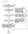
- the configuration of the functional block of the adaptive array terminal shown in Fig. 1 is actually realized by software executed by a digital signal processor (DSP), not shown, along the flow chart of Fig. 3.
- DSP reads a program including various steps of the flow chart of Fig. 3 from a memory, not shown, and executes the program.
- the program may be installed from the outside.
- step S1 an operation related to the display is automatically activated by a timer interruption, or an operation related to the display is automatically activated by an operation of the input unit by the user.
- step S2 whether the display method (for example, any of Display Methods 1 to 3 described with reference to Fig. 2) has been designated in advance by the user or not is determined.
- the display method for example, any of Display Methods 1 to 3 described with reference to Fig. 2
- step S3 a display method next to the one used last time is used as the display method (specifically, in step S3, Display Methods 1 to 3 are displayed incremented successively).
- step S2 if it is determined that the display method has been designated beforehand, the flow proceeds to step S4, and whether the designated display method is Display Method 1 of Fig. 2 (b) or not is determined.
- step S4 If it is determined in step S4 that the designated method is Display Method 1, the flow proceeds to steps S5 in which reception level values of antennas ANT#1 and ANT#2 are displayed directly, in accordance with Display Method 1 as shown in Fig. 2 (b).
- step S4 If it is determined in step S4 that the designated method is not Display Method 1, the flow proceeds to step S6 in which whether the designated display method is Display Method 2 of Fig. 2 (c) or not is determined.
- step S6 If it is determined in step S6 that the designated method is Display Method 2, the flow proceeds to steps S7 in which a difference value between reception levels of antennas ANT# 1 and ANT#2 is displayed, in accordance with Display Method 2 as shown in Fig. 2 (c).
- step S6 If it is determined in step S6 that the designated method is not Display Method 2, the flow proceeds to step S8, in which the degree of magnitude of difference value between reception levels of antennas ANT#1 and ANT#2 is displayed, in accordance with Display Method 3 as shown in Fig. 2 (d).
- reception levels of the signals of a plurality of streams received by respective ones of the plurality of antennas can be displayed (notified) to the user in various manners. Therefore, it becomes possible for the user to adjust the reception level such that reception level difference among antennas decreases by adjusting, for example, an angle of a movable antenna, that is, an angle of an antenna with another antenna, while visually monitoring the display.
- the reception performance of adaptive array processing in the adaptive array wireless communication apparatus can further be improved.
- Fig. 4 is a functional block diagram representing a configuration of an adaptive array terminal in accordance with the second embodiment of the present invention.
- the functional block diagram of Fig. 4 is the same as the functional block diagram of the first embodiment of Fig. 1 except for the following points, and description of common portions will not be repeated.
- an antenna drive control unit 8 is provided in place of (or in addition to) display unit 6 shown in Fig. 1. Further, in place of main control unit 5 controlling display unit 6 of Fig. 1, a main control unit 9 controlling antenna drive control unit 8 is provided.
- Antenna drive control unit 8 automatically drives and controls the angle adjustment of the movable antenna, of which angle can be changed by moving forward or backward, of the two antennas of the adaptive array terminals, in accordance with a control signal from main control unit 9.
- Main control unit 9 calculates the reception level difference between reception levels 1 and 2 received from RF receiving circuits 1 and 2, and if it is determined that the level difference is not smaller than a prescribed threshold value, controls antenna drive control unit 8 such that the angle of the two antennas with each other is adjusted to make the level difference not larger than the threshold value.
- the processes of determining the reception level and antenna drive control described above may be automatically activated by the adaptive array terminal, or may be activated triggered by the user operation through input unit 7.
- DSP digital signal processor
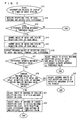
- the configuration of the functional block of the adaptive array terminal shown in Fig. 4 is actually realized by software executed by a digital signal processor (DSP), not shown, along the flow chart of Fig. 5.
- DSP reads a program including various steps of the flow chart of Fig. 5 from a memory, not shown, and executes the program.
- the program may be installed from the outside.
- step S11 an operation related to the antenna control is automatically activated by a timer interruption, or an operation related to the antenna control is automatically activated by an operation of the input portion by the user.
- step S12 the reception level difference is calculated from reception levels 1 and 2 corresponding to antennas ANT#1 and ANT#2.
- step S13 whether the calculated reception level difference is not lower than a prescribed threshold value or not is determined. If it is determined that the reception level difference is equal to or lower than the threshold value, the process is terminated.
- the angle of antenna ANT#1 is changed and reception level 1 corresponding to each angle is obtained and stored in step S14.
- step S15 the angle of antenna ANT#2 is changed and reception level 2 corresponding to each angle is obtained and stored.
- step S16 the maximum value among the obtained reception levels 1 and the maximum value among the obtained reception levels 2 are extracted, and the level difference therebetween is compared with a prescribed threshold value.
- step S17 if it is determined that the level difference is equal to or smaller than the threshold value, the flow proceeds to step S18, in which angles of antennas ANT#1 and ANT#2 are adjusted such that maximum values of reception levels 1 and 2 are attained.
- step S17 if it is determined that the level difference is not lower than the threshold value, maximum values of reception levels 1 and 2 of antennas ANT#1 and ANT#2 are compared with each other, and whether the reception level of the antenna having the smaller maximum value is the same as or lower than a prescribed threshold value or not is determined.
- step S20 If it is determined that the value is the same or lower than the threshold value, the flow proceeds to step S20, in which angels of antennas ANT#1 and ANT#2 are adjusted so that reception levels 1 and 2 both attain the maximum values. Then, the process is terminated.
- reception level of the antenna having smaller maximum value is equal to or smaller than the threshold value and is too small, it is better to attain higher reception level at each antenna even if there is considerable reception level difference, rather than to adjust the reception level using the antenna of such low reception level as the reference.
- step S19 if the reception level of the antenna having smaller maximum value is not lower than the threshold value, that is, if it is not too small, the angle of the antenna is adjusted such that the reception level of that antenna attains the maximum value, in step S21.
- step S22 the angle of the antenna having larger maximum value is adjusted such that the reception level difference from the antenna having smaller maximum value is not higher than the threshold value and the reception level attains the highest under this condition.
- the highest possible reception level can be attained while the reception level difference between the two antennas is kept within the tolerable range.
- reception level difference of signals of the plurality of streams received by respective ones of the plurality of antennas is calculated, and by automatically adjusting an angle of a movable antenna, for example, to reduce the difference, the reception level can be adjusted with higher accuracy. Therefore, the reception performance of adaptive array processing in the adaptive array wireless communication apparatus can further be improved.
- the number of antennas of the adaptive array terminal is two.
- the number is not limited to two, and it may be any number necessary for adaptive array processing. Further, it is not necessary that the plurality of antennas are all movable. Movable and unmovable antennas may exist in a mixed manner, provided that the angle between each of the antennas can be adjusted.
- an adaptive array wireless communication apparatus having a plurality of antennas, it is possible to indicate the reception levels of signals received by respective ones of the plurality of antennas. Therefore, it becomes possible for the user to adjust reception level such that reception level difference among antennas decreases by adjusting, for example, an angle of a movable antenna while visually monitoring the display.
- the reception performance of adaptive array processing in the adaptive array wireless communication apparatus can further be improved.
- reception level difference of signals of the plurality of systems received by respective ones of the plurality of antennas is calculated, and by automatically adjusting an angle of a movable antenna, for example, to reduce the difference, the reception level can be adjusted with higher accuracy. Therefore, the reception performance of adaptive array processing in the adaptive array wireless communication apparatus can further be improved.
- reception levels of a plurality of antennas are displayed to the user to make it possible for the user to adjust reception level, or, automatic adjustment of the reception level is made possible to reduce the reception level difference. Therefore, the invention is effective in an adaptive array wireless communication apparatus having a plurality of antennas.
Landscapes
- Engineering & Computer Science (AREA)
- Computer Networks & Wireless Communication (AREA)
- Signal Processing (AREA)
- Physics & Mathematics (AREA)
- Electromagnetism (AREA)
- Quality & Reliability (AREA)
- Variable-Direction Aerials And Aerial Arrays (AREA)
- Radio Transmission System (AREA)
- Mobile Radio Communication Systems (AREA)
- Monitoring And Testing Of Transmission In General (AREA)
- Telephone Function (AREA)
Abstract
In an adaptive array terminal, at least one of two antennas (ANT#1, ANT#2) is a movable antenna. A display unit (6) of the terminal displays reception levels of, or level difference between, the two antennas. Thus, it becomes possible for a user to adjust an angle of the antenna such that reception levels of the two antennas come closer to the same level. Alternatively, a control unit (8) of the terminal automatically adjusts the antenna angle so that reception level difference between the two antennas becomes not higher than a prescribed value. <IMAGE>
Description
The present invention relates to an adaptive array wireless communication
apparatus, a reception level display method, a reception level adjusting method, a
reception level display program and a reception level adjusting program. Particularly,
the present invention relates to a mobile terminal apparatus having an adaptive array
function using a plurality of antennas, and to a reception level display method, a
reception level adjusting method, a reception level display program and a reception level
adjusting program used in such a mobile terminal apparatus.
Conventionally, in a mobile communication system such as a PHS (Personal
Handyphone System), wireless communication is established between a mobile terminal
apparatus (hereinafter referred to as a terminal) and wireless base station (hereinafter
referred to as a base station).
A conventional terminal typically has one antenna, and a radio frequency (RF)
signal received by the antenna is subjected to various signal processing including
amplification and frequency conversion in an RF receiving circuit.
One such signal processing performed in the RF receiving circuit is measurement
of a reception power level (hereinafter referred to as a reception level) of the received
signal. The reception level of the signal received by the antenna measured by the RF
receiving circuit is displayed (notified) to the user on a display of the terminal, and hence,
the user can estimate radio wave environment of the terminal.
A diversity terminal having two antennas and corresponding RF receiving
circuits and selecting one of the antennas that has higher reception level as a reception
antenna has been realized and disclosed, for example, in Japanese Patent Laying-Open
No. 8-97759.
The diversity terminal has two antennas as mentioned above, and a received
signal of one stream from either one of the antennas is selected, taken in the terminal and
subjected to a signal processing for demodulation. Therefore, only the reception level
of the received signal of one stream selected for demodulation is displayed for the user.
As for the base station, an adaptive array base station has been practically
implemented, at which a signal from a specific user is received by a plurality of antennas,
and the received signals of the plurality of streams are subjected to well-known adaptive
array processing, so that the received signal from the user is separated and extracted.
Here, the adaptive array processing refers to a well-known process in which
based on received signals from terminals, a weight vector consisting of reception
coefficients (weights) of respective ones of the plurality of antennas of the base station is
estimated and adaptively controlled, so that a signal from a specific terminal can be
extracted (synthesized) accurately. As the adaptive array processing is well known,
detailed description will not be given here.
As for the terminal, an adaptive array terminal having the function of adaptive
array processing has also been developed. Such an adaptive array terminal has a
plurality of (for example, two) antennas and corresponding plurality of (two) RF
receiving circuits, and signals of a plurality of streams received by respective antennas
are taken into the terminal and subjected to the adaptive array processing.
As a characteristic of the adaptive array processing, it has been known that
better reception characteristic can be attained when reception level difference among the
plurality of antennas is smaller. Actually, however, there is reception level difference
generated among the plurality of antennas, because of difference in angle of the plurality
of antennas as well as fading.
In view of the foregoing, it is desired that the reception level difference among
the plurality of antennas is adjusted by some method, in order to improve reception
performance of the adaptive array terminal.
A terminal having two antennas, as is the case of the diversity terminal described
above, one of which is a fixed antenna provided inside the terminal and the other is a
movable antenna mounted on the outside of the terminal of which angle can be adjusted
by moving itself forward or backward, has been implemented as an example of the
conventional terminals.
Conventionally, however, the reception level display for the user is only the
reception level of the signal of one stream received and taken in the terminal as
described above, regardless of the number of antennas of the terminal.
Therefore, though the conventional terminal having a plurality of (two) antennas
employs a movable antenna allowing angle adjustment of the antenna, it has been
impossible to know the reception level of each of the plurality of antennas.
Therefore, similarly in the adaptive array terminal having a plurality of antennas,
it has been impossible for the user to know the reception level of each antenna, and
therefore, even if there is a movable antenna, it has been impossible for the user to adjust
the angle of the antenna to make smaller the reception level difference among the
reception antennas.
Further, in the conventional terminal having a plurality of antennas employing a
movable antenna, the reception level has been adjusted by the user manually adjusting
the angle of the movable antenna while visually monitoring the reception level displayed
on the terminal, which adjustment has been unsatisfactory in accuracy.
Therefore, an object of the present invention is to provide an adaptive array
wireless communication apparatus, a reception level display method, a reception level
adjusting method, a reception level display program and a reception level adjusting
program, by which it becomes possible for the user to readily adjust the reception level
of the antenna even in an adaptive array wireless communication apparatus having a
plurality of antennas.
Another object of the present invention is to provide an adaptive array wireless
communication apparatus, a reception level display method, a reception level adjusting
method, a reception level display program and a reception level adjusting program, by
which the reception level of the antenna can automatically be adjusted with high
accuracy even in an adaptive array wireless communication apparatus having a plurality
of antennas.
According to one aspect, the present invention provides an adaptive array
wireless communication apparatus having a plurality of antennas, including determining
means, display means and reception level adjusting means. The determining means
determines reception levels of signals of a plurality of streams received by respective
ones of the plurality of antennas. The display means displays the determined reception
levels of the signals of the plurality of streams. The reception level adjusting means
allows, by manual operation by the user, adjustment of the reception levels of signals of
the plurality of streams.
Preferably, the display means displays a numerical value indicative of the
reception level of each of the signals of the plurality of streams.
Preferably, the display means displays a difference value between each of the
reception levels of the signals of the plurality of streams.
Preferably, the display means displays a degree of magnitude of the difference
value between each of the reception levels of the signals of the plurality of streams.
Preferably, the display means is capable of selectively displaying, as contents of
display, any of numerical value indicative of the reception level of each of the signals of
the plurality of streams, the difference value between each of the reception levels and a
degree of magnitude of the difference value, and the adaptive array wireless
communication apparatus further includes display contents determining means for
determining the contents to be displayed by the displaying means, in accordance with
prior designation by the user.
Preferably, the display means is capable of selectively displaying, as contents of
display, any of numerical value indicative of the reception level of each of the signals of
the plurality of streams, the difference value between each of the reception levels and a
degree of magnitude of the difference value, and the adaptive array wireless
communication apparatus further includes display contents switching means for
periodically and successively switching the contents to be displayed by the display means.
Preferably, the adaptive array wireless communication apparatus further includes
activating means for automatically activating the determining means and the display
means.
Preferably, the adaptive array wireless communication apparatus further includes
activating means for activating, in response to a user instruction, the determining means
and the reception level adjusting means.
According to another aspect, the present invention provides an adaptive array
wireless communication apparatus having a plurality of antennas including determining
means, reception level difference calculating means, and reception level adjusting means.
The determining means determines reception levels of signals of a plurality of streams
received by respective ones of the plurality of antennas. The reception level difference
calculating means calculates a difference among the determined reception levels of the
signals of the plurality of streams. The reception level adjusting means adjusts the
reception levels of signals of the plurality of streams such that the calculated reception
level difference decreases.
Preferably, the reception level adjusting means includes antenna driving means
for changing an angle between each of the plurality of antennas, and control means for
controlling the antenna driving means such that the angle between each of the plurality
of antennas is changed such that the reception level difference is not higher than a
prescribed threshold value.
Preferably, the adaptive array wireless communication apparatus further includes
activating means for automatically activating the determining means and the reception
level adjusting means.
Preferably, the adaptive array wireless communication apparatus further includes
activating means for activating, in response to a user instruction, the determining means
and the reception level adjusting means.
According to a further aspect, the present invention provides a method of
displaying a reception level in an adaptive array wireless communication apparatus
having a plurality of antennas, including the step of determining reception levels of
signals of a plurality of streams received by respective ones of the plurality of antennas,
and the step of displaying the determined reception levels of signals of the plurality of
streams.
Preferably, in the display step, a numerical value indicative of the reception level
of each of the signals of the plurality of streams is displayed.
Preferably, in the display step, a difference value between each of the reception
levels of the signals of the plurality of streams is displayed.
Preferably, in the display step, a degree of magnitude of the difference value
between each of the reception levels of the signals of the plurality of streams is displayed.
Preferably, in the display step, any of a numerical value indicative of the
reception level of each of the signals of the plurality of streams, the difference value
between each of the reception levels and a degree of magnitude of the difference value
can selectively be displayed as the display contents, and the method of displaying the
reception level further includes the step of determining the contents to be displayed in
the display step in accordance with prior designation by the user.
Preferably, in the display step, any of a numerical value indicative of the
reception level of each of the signals of the plurality of streams, the difference value
between each of the reception levels and a degree of magnitude of the difference value
can selectively be displayed as the display contents, and the method of displaying the
reception level further includes the step of periodically and successively switching the
contents to be displayed in the display step.
Preferably, the method of displaying the reception level further includes the step
of automatically activating the determining step and the display step.
Preferably, the method of displaying the reception level further includes the step
of activating, in response to a user instruction, the determining step and the display step.
According to a still further aspect, the present invention provides a method of
adjusting a reception level in an adaptive array wireless communication apparatus having
a plurality of antennas including the step of determining reception levels of signals of a
plurality of streams received by respective ones of the plurality of antennas, the step of
calculating a difference among the determined reception levels of the signals of the
plurality of streams, and the step of adjusting the reception levels of signals of the
plurality of streams such that the calculated reception level difference decreases.
Preferably, the reception level adjusting step includes the step of changing an
angle between each of the plurality of antennas such that the reception level difference is
not higher than a prescribed threshold value.
Preferably, the method of adjusting reception level further includes the step of
automatically activating the determining step and the reception level adjusting step.
Preferably, the method of adjusting reception level further includes the step of
activating, in response to a user instruction, the determining step and the reception level
adjusting step.
According to a still further aspect, the present invention provides a reception
level display program in an adaptive array wireless communication apparatus having a
plurality of antennas, causing a computer to execute the step of determining reception
levels of signals of a plurality of streams received by respective ones of the plurality of
antennas, and the display step of displaying the determined reception levels of signals of
the plurality of streams.
Preferably, in the display step, a numerical value indicative of the reception level
of each of the signals of the plurality of streams is displayed.
Preferably, in the display step, a difference value between each of the reception
levels of the signals of the plurality of streams is displayed.
Preferably, in the display step, a degree of magnitude of the difference value
between each of the reception levels of the signals of the plurality of streams is displayed.
Preferably, in the display step, any of a numerical value indicative of the
reception level of each of the signals of the plurality of streams, the difference value
between each of the reception levels and a degree of magnitude of the difference value
can selectively be displayed as the display contents, and the reception level display
program causes the computer to further execute the step of determining the contents to
be displayed in the display step, in accordance with prior designation by the user.
Preferably, in the display step, any of a numerical value indicative of the
reception level of each of the signals of the plurality of streams, the difference value
between each of the reception levels and the degree of magnitude of the difference value
can selectively be displayed as the display contents, and the reception level display
program causes the computer to further execute the step of periodically and successively
switching the contents to be displayed in the display step.
Preferably, the reception level display program causes the computer to further
execute the step of automatically activating the determining step and the display step.
Preferably, the program causes the computer to further execute the step of
activating, in response to a user instruction, the determining step and the display step.
According to a further aspect, the present invention provides a reception level
adjusting program in an adaptive array wireless communication apparatus having a
plurality of antennas, causing a computer to execute the step of determining reception
levels of signals of a plurality of streams received by respective ones of the plurality of
antennas, the step of calculating a difference value between each of the determined
reception levels of the signals of the plurality of streams, and the step of adjusting the
reception levels of signals of the plurality of streams such that the calculated reception
level difference becomes smaller.
Preferably, the reception level adjusting step includes the step of changing an
angle between each of the plurality of antennas such that the reception level difference is
not higher than a prescribed threshold value.
Preferably, the reception level adjusting program causes the computer to further
execute the step of automatically activating the determining step and the reception level
adjusting step.
Preferably, the reception level adjusting program causes the computer to further
execute the step of activating, in response to a user instruction, the determining step and
the reception level adjusting step.
Therefore, according to the present invention, in an adaptive array wireless
communication apparatus having a plurality of antennas, the reception levels of signals
of a plurality of streams received by respective ones of the plurality of antennas can be
displayed to the user. Therefore, it becomes possible for the user to adjust reception
level such that reception level difference among antennas decreases by adjusting, for
example, an angle of a movable antenna while visually monitoring the display. Thus,
the reception performance of adaptive array processing in the adaptive array wireless
communication apparatus can further be improved.
Further, according to the present invention, in an adaptive array wireless
communication apparatus having a plurality of antennas, reception level difference of
signals of the plurality of streams received by respective ones of the plurality of antennas
is calculated, and by automatically adjusting an angle of a movable antenna, for example,
to reduce the difference, the reception level can be adjusted with higher accuracy.
Therefore, the reception performance of adaptive array processing in the adaptive array
wireless communication apparatus can further be improved.
In the following, embodiments of the present invention will be described in detail
with reference to the figures. In the figures, the same or corresponding portions will be
denoted by the same reference characters and description thereof will not be repeated.
Fig. 1 is a functional block diagram representing a configuration of an adaptive
array terminal in accordance with a first embodiment of the present invention.
A wireless downlink signal from a base station, not shown, is received by
antennas ANT# 1 and ANT# 2, respectively, and applied as RF signals of radio frequency
to corresponding RF receiving circuits 1 and 2.
In each of RF receiving circuits 1 and 2, the received RF signal is subjected to
prescribed analog processing such as amplification and frequency conversion, and the
resulting signal is applied to a signal processing unit 3. Under the control of a main
control unit 5, signal processing unit 3 performs the adaptive array processing on the
signals received from RF receiving circuits 1 and 2, whereby desired reception signals
are separated and extracted.
Specifically, in signal processing unit 3, a well-known adaptive array processing
is performed, in which based on the reception signals from the base station, a weight
vector consisting of weights of two antennas ANT# 1 and ANT# 2 of the terminal is
estimated and adaptively controlled, so that the desired signal from the base station is
extracted (synthesized) accurately.
The signal processing unit 3 shown in Fig. 1 includes a weight control unit, not
shown, for estimating the weight vector for each symbol of the received signal, and the
weight control unit executes a process of converging the weight vector such that a
square of a difference between a complex multiplication sum of the received signal
vector and the estimated weight vector and a known reference signal decreases, that is,
the adaptive array processing of converging the reception directivity from the base
station.
In the adaptive array processing, such a convergence of weight vector is
performed adaptively in accordance with time and variation of propagation path
characteristics of signal waves, so that interference components and noise can be
removed from the received signal and the signal from the base station can be extracted.
In the weight control unit as such, sequential estimation algorithm such as RLS
(Recursive Least Squares) algorithm or LMS (Least Mean Square) algorithm is used.
RLS algorithm and LMS algorithm are well known in the field of adaptive array
processing and described in detail, for example, in Adaptive Signal Processing by Array
Antenna by Nobuyoshi Kikuma (Kagaku Gijutsu Shuppan), published on November 25,
1998, "Chapter 3: MMSE Adaptive Array" on pp. 35-49 and, therefore, detailed
description of adaptive array processing will not be given here.
Further, a demodulating unit 4 shown in Fig. 1 performs, under the control by
main control unit 5, a demodulating process on the received signal separated and
extracted by the adaptive array processing at signal processing unit 3, and outputs
demodulated bit outputs.
In RF receiving circuits 1 and 2, reception levels of the received signals are
measured, and reception level 1 from RF receiving circuit 1 and reception level 2 from
RF receiving circuit 2, respectively, are applied to main control unit 5.
Fig. 2 is a schematic diagram representing an exemplary method of displaying the
reception level of the adaptive array terminal in accordance with a first embodiment of
the present invention.
In Fig. 2, (a) schematically shows a frontal view of an adaptive array terminal
100. Referring to Fig. 2 (a), adaptive array terminal 100 has two antennas ANT# 1 and
ANT# 2, at least one of which is a movable antenna that can be moved forward and
backward, allowing adjustment of an angle with the other antenna.
It is assumed that adaptive array terminal 100 has the display unit corresponding
to display unit 6 of Fig. 1 implemented by an LED and/or LCD. In the following, the
manner of displaying the reception level using these display units will be described.
Fig. 2 (b) shows an exemplary Display Method 1 in accordance with the first
embodiment of the present invention. In Display Method 1, reception levels of two
antennas ANT# 1 and AND#2 are displayed directly as numerical values based on
reception levels 1 and 2 from RF receiving circuits 1 and 2, on the display unit formed of
LCD on adaptive array terminal 100, by an instruction from main control unit 5.
For instance, in the example of Fig. 2 (b), as the image on the display unit
formed of LCD, 30 dBµV as the reception level of antenna ANT# 1 and 32 dBµV as the
reception level of antenna ANT# 2 are displayed.
Visually monitoring the display, the user manually adjusts the angle of movable
antenna so that the two antennas come to have the same reception levels.
Next, Fig. 2 (c) shows an exemplary Display Method 2 in accordance with the
first embodiment of the present invention. In Display Method 2, reception level
difference between reception levels of two antennas ANT# 1 and ANT# 2 is calculated by
main control unit 5 based on reception levels 1 and 2 from RF receiving circuits 1 and 2,
and is displayed as a difference value, on the display unit formed of an LCD on adaptive
array terminal 100.
For instance, in the example of Fig. 2 (c), as the image on the display unit
formed of LCD, 2 dBµV is displayed as the difference value between the reception level
of antenna ANT# 1 and the reception level of antenna ANT# 2.
Visually monitoring the display, the user manually adjusts the angle of movable
antenna so that the reception level difference between the two antennas becomes zero
level.
Next, Fig. 2 (d) shows an exemplary Display Method 3 in accordance with the
first embodiment of the present invention. In Display Method 3, reception level
difference between reception levels of two antennas ANT# 1 and ANT# 2 is calculated by
main control unit 5 based on reception levels 1 and 2 from RF receiving circuits 1 and 2,
and is displayed as a degree of magnitude of difference value, on the display unit formed
of an LCD.
By way of example, such a degree of magnitude of difference value may be
determined by main control unit 5, in which the magnitude of difference value is
compared with a prescribed threshold value or values to be classified into three, that is,
large, medium and small.
In the example of Fig. 2 (d-1), as an image on the display unit formed of LCD,
"small" is displayed as the degree of magnitude of difference value between the
reception level of antenna ANT# 1 and reception level of antenna ANT# 2.
In the example of Fig. 2 (d-2), as an image on the display unit formed of three
LEDs, one LED corresponding to "small" as the degree of magnitude of difference
value between the reception level of antenna ANT# 1 and reception level of antenna
ANT# 2 is turned on.
In the example of Fig. 2 (d-3), as an image on the display unit formed of one
LED, the LED is turned on with flicker rate or with a color corresponding to "small" as
the degree of magnitude of difference value between the reception level of antenna
ANT# 1 and reception level of antenna ANT# 2.
For instance, if the degree of magnitude of difference value is "large", the LED
may be flickered at a high rate, if it is "middle", the LED may be flickered at a middle
rate, and if it is "small", the LED may be kept on without flickering.
Alternatively, if the degree of magnitude of difference value is "large", red light
may be emitted from the LED, if it is "middle", yellow light may be emitted from the
LED, and if it is "small", green light may be emitted.
Visually monitoring the display, the user manually adjusts the angle of movable
antenna so that the reception level difference between the two antennas becomes smaller.
As for the selection of Display Methods 1 to 3 described above, the user may
designate the method by an operation through input unit 7 beforehand, or Display
Methods 1 to 3 may be periodically and successively switched.
Further, the processes of determining and displaying reception level described
above may be automatically activated by the adaptive array terminal, or may be activated
triggered by the user operation through input unit 7.
The configuration of the functional block of the adaptive array terminal shown in
Fig. 1 is actually realized by software executed by a digital signal processor (DSP), not
shown, along the flow chart of Fig. 3. DSP reads a program including various steps of
the flow chart of Fig. 3 from a memory, not shown, and executes the program. The
program may be installed from the outside.
In the following, an operation of the adaptive array terminal in accordance with
the first embodiment of the present invention will be described.
First, in step S1, an operation related to the display is automatically activated by
a timer interruption, or an operation related to the display is automatically activated by
an operation of the input unit by the user.
In step S2, whether the display method (for example, any of Display Methods 1
to 3 described with reference to Fig. 2) has been designated in advance by the user or
not is determined.
When the method is not specifically designated, in step S3, a display method next
to the one used last time is used as the display method (specifically, in step S3, Display
Methods 1 to 3 are displayed incremented successively).
In step S2, if it is determined that the display method has been designated
beforehand, the flow proceeds to step S4, and whether the designated display method is
Display Method 1 of Fig. 2 (b) or not is determined.
If it is determined in step S4 that the designated method is Display Method 1, the
flow proceeds to steps S5 in which reception level values of antennas ANT# 1 and
ANT# 2 are displayed directly, in accordance with Display Method 1 as shown in Fig. 2
(b).
If it is determined in step S4 that the designated method is not Display Method 1,
the flow proceeds to step S6 in which whether the designated display method is Display
Method 2 of Fig. 2 (c) or not is determined.
If it is determined in step S6 that the designated method is Display Method 2, the
flow proceeds to steps S7 in which a difference value between reception levels of
antennas ANT# 1 and ANT# 2 is displayed, in accordance with Display Method 2 as
shown in Fig. 2 (c).
If it is determined in step S6 that the designated method is not Display Method 2,
the flow proceeds to step S8, in which the degree of magnitude of difference value
between reception levels of antennas ANT# 1 and ANT# 2 is displayed, in accordance
with Display Method 3 as shown in Fig. 2 (d).
By the repetition of the above described processes, when the display method has
been designated by the user, the display is given in the designated display method, and
otherwise, Display Methods 1 to 3 are successively repeated.
As described above, according to the first embodiment of the present invention,
in an adaptive array terminal having a plurality of antennas, reception levels of the
signals of a plurality of streams received by respective ones of the plurality of antennas
can be displayed (notified) to the user in various manners. Therefore, it becomes
possible for the user to adjust the reception level such that reception level difference
among antennas decreases by adjusting, for example, an angle of a movable antenna,
that is, an angle of an antenna with another antenna, while visually monitoring the
display. Thus, the reception performance of adaptive array processing in the adaptive
array wireless communication apparatus can further be improved.
Fig. 4 is a functional block diagram representing a configuration of an adaptive
array terminal in accordance with the second embodiment of the present invention.
The functional block diagram of Fig. 4 is the same as the functional block diagram of the
first embodiment of Fig. 1 except for the following points, and description of common
portions will not be repeated.
Specifically, in the functional block diagram of Fig. 4, in place of (or in addition
to) display unit 6 shown in Fig. 1, an antenna drive control unit 8 is provided. Further,
in place of main control unit 5 controlling display unit 6 of Fig. 1, a main control unit 9
controlling antenna drive control unit 8 is provided.
Antenna drive control unit 8 automatically drives and controls the angle
adjustment of the movable antenna, of which angle can be changed by moving forward
or backward, of the two antennas of the adaptive array terminals, in accordance with a
control signal from main control unit 9.
Main control unit 9 calculates the reception level difference between reception
levels 1 and 2 received from RF receiving circuits 1 and 2, and if it is determined that the
level difference is not smaller than a prescribed threshold value, controls antenna drive
control unit 8 such that the angle of the two antennas with each other is adjusted to
make the level difference not larger than the threshold value.
The processes of determining the reception level and antenna drive control
described above may be automatically activated by the adaptive array terminal, or may
be activated triggered by the user operation through input unit 7.
The configuration of the functional block of the adaptive array terminal shown in
Fig. 4 is actually realized by software executed by a digital signal processor (DSP), not
shown, along the flow chart of Fig. 5. DSP reads a program including various steps of
the flow chart of Fig. 5 from a memory, not shown, and executes the program. The
program may be installed from the outside.
In the following, an operation of the adaptive array terminal in accordance with
the second embodiment of the present invention will be described with reference to Fig.
5. In the following description, it is assumed that two antennas provided on the
adaptive array terminal are both movable antennas of which angles can be changed.
First, in step S11, an operation related to the antenna control is automatically
activated by a timer interruption, or an operation related to the antenna control is
automatically activated by an operation of the input portion by the user.
Thereafter, in step S12, the reception level difference is calculated from
reception levels 1 and 2 corresponding to antennas ANT# 1 and ANT# 2.
Next, in step S13, whether the calculated reception level difference is not lower
than a prescribed threshold value or not is determined. If it is determined that the
reception level difference is equal to or lower than the threshold value, the process is
terminated.
If it is determined that the reception level difference is not lower than the
prescribed threshold value, the angle of antenna ANT# 1 is changed and reception level 1
corresponding to each angle is obtained and stored in step S14.
Next, in step S15, the angle of antenna ANT# 2 is changed and reception level 2
corresponding to each angle is obtained and stored.
Then, in step S16, the maximum value among the obtained reception levels 1 and
the maximum value among the obtained reception levels 2 are extracted, and the level
difference therebetween is compared with a prescribed threshold value.
In step S17, if it is determined that the level difference is equal to or smaller than
the threshold value, the flow proceeds to step S18, in which angles of antennas ANT# 1
and ANT# 2 are adjusted such that maximum values of reception levels 1 and 2 are
attained.
In step S17, if it is determined that the level difference is not lower than the
threshold value, maximum values of reception levels 1 and 2 of antennas ANT# 1 and
ANT# 2 are compared with each other, and whether the reception level of the antenna
having the smaller maximum value is the same as or lower than a prescribed threshold
value or not is determined.
If it is determined that the value is the same or lower than the threshold value,
the flow proceeds to step S20, in which angels of antennas ANT# 1 and ANT# 2 are
adjusted so that reception levels 1 and 2 both attain the maximum values. Then, the
process is terminated.
The reason for this is as follows. If the reception level of the antenna having
smaller maximum value is equal to or smaller than the threshold value and is too small, it
is better to attain higher reception level at each antenna even if there is considerable
reception level difference, rather than to adjust the reception level using the antenna of
such low reception level as the reference.
In step S19, if the reception level of the antenna having smaller maximum value
is not lower than the threshold value, that is, if it is not too small, the angle of the
antenna is adjusted such that the reception level of that antenna attains the maximum
value, in step S21.
Next, in step S22, the angle of the antenna having larger maximum value is
adjusted such that the reception level difference from the antenna having smaller
maximum value is not higher than the threshold value and the reception level attains the
highest under this condition.
Thus, the highest possible reception level can be attained while the reception
level difference between the two antennas is kept within the tolerable range.
As described above, in the second embodiment of the present invention, in an
adaptive array terminal having a plurality of antennas, reception level difference of
signals of the plurality of streams received by respective ones of the plurality of antennas
is calculated, and by automatically adjusting an angle of a movable antenna, for example,
to reduce the difference, the reception level can be adjusted with higher accuracy.
Therefore, the reception performance of adaptive array processing in the adaptive array
wireless communication apparatus can further be improved.
In the first and second embodiments described above, the number of antennas of
the adaptive array terminal is two. The number is not limited to two, and it may be any
number necessary for adaptive array processing. Further, it is not necessary that the
plurality of antennas are all movable. Movable and unmovable antennas may exist in a
mixed manner, provided that the angle between each of the antennas can be adjusted.
As described above, according to the present invention, in an adaptive array
wireless communication apparatus having a plurality of antennas, it is possible to
indicate the reception levels of signals received by respective ones of the plurality of
antennas. Therefore, it becomes possible for the user to adjust reception level such
that reception level difference among antennas decreases by adjusting, for example, an
angle of a movable antenna while visually monitoring the display. Thus, the reception
performance of adaptive array processing in the adaptive array wireless communication
apparatus can further be improved.
Further, according to the present invention, in an adaptive array wireless
communication apparatus having a plurality of antennas, reception level difference of
signals of the plurality of systems received by respective ones of the plurality of antennas
is calculated, and by automatically adjusting an angle of a movable antenna, for example,
to reduce the difference, the reception level can be adjusted with higher accuracy.
Therefore, the reception performance of adaptive array processing in the adaptive array
wireless communication apparatus can further be improved.
According to the present invention, reception levels of a plurality of antennas are
displayed to the user to make it possible for the user to adjust reception level, or,
automatic adjustment of the reception level is made possible to reduce the reception
level difference. Therefore, the invention is effective in an adaptive array wireless
communication apparatus having a plurality of antennas.
Claims (16)
- An adaptive array wireless communication apparatus having a plurality of antennas (ANT#1, ANT#2), comprising:determining means (5) for determining reception levels of signals of a plurality of streams received by respective ones of said plurality of antennas;display means (6) for displaying said determined reception levels of signals of said plurality of streams; andreception level adjusting means manually operated by a user for adjusting the reception levels of signals of said plurality of streams.
- An adaptive array wireless communication apparatus having a plurality of antennas (ANT#1, ANT#2), comprising:determining means (9) for determining reception levels of signals of a plurality of streams received by respective ones of said plurality of antennas;reception level difference calculating means (9) for calculating a difference among said determined reception levels of signals of said plurality of streams; andreception level adjusting means (8) for adjusting the reception levels of signals of said plurality of streams such that said calculated reception level difference decreases.
- A method of displaying a reception level in an adaptive array wireless communication apparatus having a plurality of antennas (ANT#1, ANT#2), comprising the steps of:determining reception levels of signals of a plurality of streams received by respective ones of said plurality of antennas; anddisplaying said determined reception levels of signals of said plurality of streams.
- A method of adjusting a reception level in an adaptive array wireless communication apparatus having a plurality of antennas (ANT#1, ANT#2), comprising the steps of:determining reception levels of signals of a plurality of streams received by respective ones of said plurality of antennas;calculating a difference among said determined reception levels of signals of said plurality of streams; andadjusting the reception levels of signals of said plurality of streams such that said calculated reception level difference decreases.
- A reception level display program for an adaptive array wireless communication apparatus having a plurality of antennas (ANT#1, ANT#2), causing a computer to execute the steps of
determining reception levels of signals of a plurality of streams received by respective ones of said plurality of antennas; and
displaying said determined reception levels of signals of said plurality of streams. - The reception level display program according to claim 5, wherein
in said display step, a numerical value indicating a reception level of each of the signals of said plurality of streams is displayed. - The reception level display program according to claim 5, wherein
in said display step, a difference value between each of the reception levels of the signals of the plurality of streams is displayed. - The reception level display program according to claim 5, wherein
in said display step, a degree of magnitude of a difference value between each of the reception levels of the signals of the plurality of streams is displayed. - The reception level display program according to claim 5, wherein
in said display step, any of said numerical value indicative of the reception level of each of the signals of said plurality of streams, said difference value between each of the reception levels and said degree of magnitude of the difference value can selectively be displayed as display contents;
said program causing the computer to further execute the step of determining the contents to be displayed in the display step, in accordance with prior designation by a user. - The reception level display program according to claim 5, wherein
in said display step, any of said numerical value indicative of the reception level of each of the signals of said plurality of streams, said difference value between each of the reception levels and said degree of magnitude of the difference value can selectively be displayed as display contents;
said program causing the computer to further execute the step of periodically and successively switching the display contents to be displayed in said display step. - The reception level display program according to claim 5, causing the computer to further execute the step of
automatically activating said determining step and said display step. - The reception level display program according to claim 5, causing the computer to further execute the step of
activating said determining step and said display step in response to a user instruction. - A reception level adjusting program in an adaptive array wireless communication apparatus having a plurality of antennas (ANT#1, ANT#2), causing a computer to execute the steps of
determining reception levels of signals of a plurality of streams received by respective ones of said plurality of antennas,
calculating a difference value between each of said determined reception levels of the signals of said plurality of streams, and
adjusting the reception levels of signals of said plurality of streams such that said calculated reception level difference becomes smaller. - The reception revel adjusting program according to claim 13, wherein
said reception level adjusting step includes the step of
changing an angle between each of said plurality of antennas such that the reception level difference is not higher than a prescribed threshold value. - The reception revel adjusting program according to claim 13, causing the computer to further execute the step of
automatically activating said determining step and said display step. - The reception revel adjusting program according to claim 13, causing the computer to further execute the step of
activating said determining step and said display step in response to a user instruction.
Applications Claiming Priority (3)
| Application Number | Priority Date | Filing Date | Title |
|---|---|---|---|
| JP2002274409A JP4217043B2 (en) | 2002-09-20 | 2002-09-20 | Adaptive array radio communication apparatus, reception level display method, reception level adjustment method, reception level display program, and reception level adjustment program |
| JP2002274409 | 2002-09-20 | ||
| PCT/JP2003/011179 WO2004028033A1 (en) | 2002-09-20 | 2003-09-01 | Adaptive array radio communication apparatus, reception level displaying method, reception level adjusting method, reception level displaying program, and reception level adjusting program |
Publications (1)
| Publication Number | Publication Date |
|---|---|
| EP1551114A1 true EP1551114A1 (en) | 2005-07-06 |
Family
ID=32024999
Family Applications (1)
| Application Number | Title | Priority Date | Filing Date |
|---|---|---|---|
| EP03797540A Withdrawn EP1551114A1 (en) | 2002-09-20 | 2003-09-01 | Adaptive array radio communication apparatus, reception level displaying method, reception level adjusting method, reception level displaying program, and reception level adjusting program |
Country Status (7)
| Country | Link |
|---|---|
| US (2) | US7583983B2 (en) |
| EP (1) | EP1551114A1 (en) |
| JP (1) | JP4217043B2 (en) |
| CN (1) | CN1682467A (en) |
| AU (1) | AU2003261880A1 (en) |
| TW (1) | TWI233277B (en) |
| WO (1) | WO2004028033A1 (en) |
Families Citing this family (12)
| Publication number | Priority date | Publication date | Assignee | Title |
|---|---|---|---|---|
| JP4217043B2 (en) * | 2002-09-20 | 2009-01-28 | 京セラ株式会社 | Adaptive array radio communication apparatus, reception level display method, reception level adjustment method, reception level display program, and reception level adjustment program |
| US20060152482A1 (en) * | 2005-01-07 | 2006-07-13 | Chauncy Godwin | Virtual interface and control device |
| JP2006217272A (en) | 2005-02-03 | 2006-08-17 | Funai Electric Co Ltd | Setting device of antenna |
| US8027879B2 (en) * | 2005-11-05 | 2011-09-27 | Jumptap, Inc. | Exclusivity bidding for mobile sponsored content |
| JP2007184826A (en) | 2006-01-10 | 2007-07-19 | Omron Corp | transceiver |
| KR101513637B1 (en) * | 2008-12-31 | 2015-04-20 | 엘지전자 주식회사 | Mobile terminal having multiple antenna and antenna information displaying method thereof |
| WO2010079536A1 (en) * | 2009-01-07 | 2010-07-15 | パナソニック株式会社 | Reader/writer |
| EP2482581B1 (en) * | 2011-01-28 | 2014-04-30 | Swisscom AG | User-controlled method and system for modifying the radiation of a wireless device in one or more user-selected volumes |
| WO2016089366A1 (en) * | 2014-12-02 | 2016-06-09 | Hewlett-Packard Development Company, L. P. | Mobile computing device including a graphical indicator |
| JP2018037967A (en) * | 2016-09-02 | 2018-03-08 | オムロン株式会社 | Wireless communication apparatus, wireless communication system, and wireless communication state confirmation method |
| JP7008256B2 (en) * | 2018-04-10 | 2022-01-25 | パナソニックIpマネジメント株式会社 | Radio environment display system and radio environment display method |
| KR20230032083A (en) * | 2021-08-30 | 2023-03-07 | 삼성전자주식회사 | Electronic device and method for controlling setting of antenna in the electronic device comprising a plurality of antennas |
Family Cites Families (43)
| Publication number | Priority date | Publication date | Assignee | Title |
|---|---|---|---|---|
| DE69103196T2 (en) * | 1990-04-27 | 1995-02-23 | Nippon Telegraph & Telephone | Antenna selection diversity reception system. |
| JPH0468622A (en) * | 1990-07-04 | 1992-03-04 | Fujitsu Ltd | Space diversity receiver |
| US5239698A (en) * | 1990-09-28 | 1993-08-24 | Motorola, Inc. | Linear weighting method and device for diversity reception |
| WO1994019704A1 (en) * | 1993-02-26 | 1994-09-01 | Fujitsu Limited | Apparatus for measuring speed of movement in mobile communication system |
| US5442356A (en) | 1994-03-23 | 1995-08-15 | The United States Of America As Represented By The Secretary Of The Navy | Airborne system for operation in conjunction with a marker beacon |
| US5486843A (en) * | 1994-06-23 | 1996-01-23 | Motorola, Inc. | Signal level indicator and associated method |
| JPH0884104A (en) * | 1994-09-09 | 1996-03-26 | Toshiba Corp | Wireless communication device |
| US6151515A (en) * | 1994-09-14 | 2000-11-21 | Mitsubishi Wireless Communications Inc. | 7, 8 segment display for mobile radio telephone |
| JP3367218B2 (en) | 1994-09-27 | 2003-01-14 | 三菱電機株式会社 | Antenna device for portable radio |
| JP3351642B2 (en) * | 1994-12-20 | 2002-12-03 | 富士通株式会社 | Phase jitter extraction circuit and phase jitter cancellation circuit |
| JPH08321799A (en) | 1995-05-25 | 1996-12-03 | Nippondenso Co Ltd | Wireless communication device and communication system |
| JPH0964640A (en) | 1995-08-29 | 1997-03-07 | Fujitsu Ltd | Wireless terminal |
| US5797083A (en) * | 1995-12-22 | 1998-08-18 | Hughes Electronics Corporation | Self-aligning satellite receiver antenna |
| JPH09205390A (en) * | 1996-01-25 | 1997-08-05 | Hitachi Denshi Ltd | Space diversity antenna installation method and mobile communication device using the same |
| JPH09321677A (en) | 1996-05-29 | 1997-12-12 | Nec Corp | Antenna control device |
| JP3272246B2 (en) * | 1996-07-12 | 2002-04-08 | 株式会社東芝 | Digital broadcast receiver |
| US6035183A (en) * | 1997-12-09 | 2000-03-07 | Nortel Networks Corporation | Basestation RSSI and BER feedback signal quality display and transmit diversity |
| JPH11215538A (en) * | 1998-01-26 | 1999-08-06 | Matsushita Electric Ind Co Ltd | Mobile station device, base station device, and mobile communication system |
| JPH11234197A (en) | 1998-02-12 | 1999-08-27 | Kokusai Electric Co Ltd | Mobile communication system using adaptive array antenna |
| JP2000059278A (en) * | 1998-08-03 | 2000-02-25 | Matsushita Electric Ind Co Ltd | Wireless communication device |
| KR100293997B1 (en) * | 1998-08-10 | 2001-07-12 | 윤종용 | Method for displaying status of cordless telephone set |
| US6704557B1 (en) * | 1999-04-22 | 2004-03-09 | Lucent Technologies Inc. | System and method for protecting a receiver from jamming interference |
| JP2001186069A (en) | 1999-12-24 | 2001-07-06 | Toshiba Corp | Mobile radio terminal |
| JP3477132B2 (en) | 1999-12-27 | 2003-12-10 | 株式会社東芝 | Arrival azimuth measuring device for incoming wave |
| JP4318389B2 (en) * | 2000-04-03 | 2009-08-19 | 三洋電機株式会社 | Adaptive array device, wireless base station, mobile phone |
| JP2001320310A (en) | 2000-05-09 | 2001-11-16 | Nec Corp | Diversity wireless transceiver |
| JP3699883B2 (en) | 2000-06-29 | 2005-09-28 | 松下電器産業株式会社 | Radio base station apparatus and radio communication method |
| US7133446B1 (en) * | 2000-10-19 | 2006-11-07 | 3Com Corporation | Performance indicator for wireless digital signal reception |
| JP2002135198A (en) * | 2000-10-20 | 2002-05-10 | Hitachi Kokusai Electric Inc | Mobile terminal |
| JP2002176384A (en) * | 2000-12-07 | 2002-06-21 | Hitachi Kokusai Electric Inc | Receiving machine |
| JP2002261668A (en) * | 2001-03-01 | 2002-09-13 | Hitachi Kokusai Electric Inc | Communication equipment |
| US6907276B2 (en) * | 2001-03-21 | 2005-06-14 | Nec Corporation | Mobile communication terminal with external display unit |
| JP4010782B2 (en) * | 2001-07-19 | 2007-11-21 | 三洋電機株式会社 | Wireless terminal device and its reception operation control program |
| JP3540784B2 (en) * | 2001-08-24 | 2004-07-07 | 三洋電機株式会社 | Radio base station, transmission power control method, and transmission power control program |
| JP2003078462A (en) * | 2001-08-31 | 2003-03-14 | Sanyo Electric Co Ltd | Wireless device, its signal receiving method, its filter coefficient measuring method, and its filter coefficient measuring program |
| US7072627B2 (en) * | 2002-06-27 | 2006-07-04 | Microsoft Corporation | Method and apparatus for adjusting signal component strength |
| JP3973506B2 (en) * | 2002-07-19 | 2007-09-12 | 三洋電機株式会社 | Wireless receiving apparatus, wireless receiving method, and wireless receiving program |
| JP4217043B2 (en) * | 2002-09-20 | 2009-01-28 | 京セラ株式会社 | Adaptive array radio communication apparatus, reception level display method, reception level adjustment method, reception level display program, and reception level adjustment program |
| KR20040062829A (en) * | 2003-01-03 | 2004-07-09 | 삼성전자주식회사 | Method for displaying indicator of received signal sensitivity in multi-functional mobile |
| JP2004254111A (en) * | 2003-02-20 | 2004-09-09 | Sanyo Electric Co Ltd | Adaptive array radio communication equipment, antenna correlation display method, antenna correlation adjustment method, antenna correlation display program and antenna correlation adjustment program |
| JP3843077B2 (en) * | 2003-03-26 | 2006-11-08 | 三洋電機株式会社 | Wireless receiving apparatus, adaptive array processing control method, and adaptive array processing control program |
| US7085909B2 (en) * | 2003-04-29 | 2006-08-01 | International Business Machines Corporation | Method, system and computer program product for implementing copy-on-write of a file |
| JP2006217272A (en) * | 2005-02-03 | 2006-08-17 | Funai Electric Co Ltd | Setting device of antenna |
-
2002
- 2002-09-20 JP JP2002274409A patent/JP4217043B2/en not_active Expired - Fee Related
-
2003
- 2003-09-01 WO PCT/JP2003/011179 patent/WO2004028033A1/en not_active Ceased
- 2003-09-01 AU AU2003261880A patent/AU2003261880A1/en not_active Abandoned
- 2003-09-01 CN CNA038219166A patent/CN1682467A/en active Pending
- 2003-09-01 US US10/528,097 patent/US7583983B2/en not_active Expired - Fee Related
- 2003-09-01 EP EP03797540A patent/EP1551114A1/en not_active Withdrawn
- 2003-09-02 TW TW092124164A patent/TWI233277B/en not_active IP Right Cessation
-
2007
- 2007-11-08 US US11/937,116 patent/US8024002B2/en not_active Expired - Fee Related
Non-Patent Citations (1)
| Title |
|---|
| See references of WO2004028033A1 * |
Also Published As
| Publication number | Publication date |
|---|---|
| WO2004028033A1 (en) | 2004-04-01 |
| US20080085739A1 (en) | 2008-04-10 |
| JP4217043B2 (en) | 2009-01-28 |
| TWI233277B (en) | 2005-05-21 |
| JP2004112573A (en) | 2004-04-08 |
| US8024002B2 (en) | 2011-09-20 |
| US7583983B2 (en) | 2009-09-01 |
| AU2003261880A1 (en) | 2004-04-08 |
| TW200412051A (en) | 2004-07-01 |
| US20060009268A1 (en) | 2006-01-12 |
| CN1682467A (en) | 2005-10-12 |
Similar Documents
| Publication | Publication Date | Title |
|---|---|---|
| US8024002B2 (en) | Adaptive array wireless communication apparatus, reception level display method, reception level adjusting method, reception level display program and reception level adjusting program | |
| EP0924876B1 (en) | Data communication apparatus and method with antennas diversity | |
| US9590703B2 (en) | Modal cognitive diversity for mobile communication systems | |
| US7551699B2 (en) | Method and apparatus for controlling a smart antenna using metrics derived from a single carrier digital signal | |
| US7565171B2 (en) | Radio base system, transmission directional control method, and transmission directional control program | |
| JP2001251125A (en) | Adaptive signal processing method and system for antenna array | |
| KR20040046071A (en) | Method for displaying antenna-ba of terminal | |
| US6836244B2 (en) | Radio reception apparatus capable of selecting from adaptive array reception mode and single route reception mode, and method and program for controlling adaptive array processing | |
| JPH0884104A (en) | Wireless communication device | |
| US7324047B2 (en) | Adaptive antenna apparatus for selecting adaptive control processing according to detected signal quality and radio communication apparatus using the same | |
| US7660561B2 (en) | Method and system for implementing smart antennas and diversity techniques | |
| KR20030022276A (en) | Mobile communication terminal, communication method, and program | |
| US20040165685A1 (en) | Adaptive array radio communication apparatus, antenna correlation display method, antenna correlation adjustment method, antenna correlation display program, and antenna correlation adjustment progam | |
| KR20100032938A (en) | Mobile unit using w-cdma scheme having reception diversity function | |
| KR100960916B1 (en) | Diversity Receiver and Control Method of Diversity Reception | |
| EP1489757A1 (en) | Radio reception device, array parameter optimal value estimation method, and array parameter optimal value estimation program | |
| US7398098B2 (en) | Radio base apparatus, transmission power control method, and transmission power control program | |
| KR100841297B1 (en) | Mixing Method of Beamforming and Diversity Technique in Mobile Communication System with Multiple Antennas and Apparatus therefor | |
| JPH11275062A (en) | Diversity receiver | |
| KR100517972B1 (en) | Receive aparatus and method for wcdma smart antenna system in using beam former | |
| JP2005020217A (en) | Mobile wireless terminal | |
| JPH09331281A (en) | Transmitter / receiver for transmitting diversity | |
| JP2007027908A (en) | Adaptive array antenna receiver and control method thereof | |
| KR20050052593A (en) | Apparatus and method for selecting transmit path using smart antenna | |
| HK1067003A (en) | Radio reception apparatus, method and program capable of selecting from adaptive array reception mode and single route reception mode |
Legal Events
| Date | Code | Title | Description |
|---|---|---|---|
| PUAI | Public reference made under article 153(3) epc to a published international application that has entered the european phase |
Free format text: ORIGINAL CODE: 0009012 |
|
| 17P | Request for examination filed |
Effective date: 20050419 |
|
| AK | Designated contracting states |
Kind code of ref document: A1 Designated state(s): AT BE BG CH CY CZ DE DK EE ES FI FR GB GR HU IE IT LI LU MC NL PT RO SE SI SK TR |
|
| AX | Request for extension of the european patent |
Extension state: AL LT LV MK |
|
| DAX | Request for extension of the european patent (deleted) | ||
| RBV | Designated contracting states (corrected) |
Designated state(s): DE FI SE |
|
| STAA | Information on the status of an ep patent application or granted ep patent |
Free format text: STATUS: THE APPLICATION HAS BEEN WITHDRAWN |
|
| 18W | Application withdrawn |
Effective date: 20090610 |