EP1551083A1 - Locking device - Google Patents
Locking device Download PDFInfo
- Publication number
- EP1551083A1 EP1551083A1 EP04028365A EP04028365A EP1551083A1 EP 1551083 A1 EP1551083 A1 EP 1551083A1 EP 04028365 A EP04028365 A EP 04028365A EP 04028365 A EP04028365 A EP 04028365A EP 1551083 A1 EP1551083 A1 EP 1551083A1
- Authority
- EP
- European Patent Office
- Prior art keywords
- threads
- united
- cable
- external
- central opening
- Prior art date
- Legal status (The legal status is an assumption and is not a legal conclusion. Google has not performed a legal analysis and makes no representation as to the accuracy of the status listed.)
- Granted
Links
- 230000002427 irreversible effect Effects 0.000 claims description 2
- 239000012778 molding material Substances 0.000 claims description 2
- 238000010276 construction Methods 0.000 description 1
- 230000001419 dependent effect Effects 0.000 description 1
- 239000000463 material Substances 0.000 description 1
- 239000004753 textile Substances 0.000 description 1
Images

Classifications
-
- H—ELECTRICITY
- H02—GENERATION; CONVERSION OR DISTRIBUTION OF ELECTRIC POWER
- H02G—INSTALLATION OF ELECTRIC CABLES OR LINES, OR OF COMBINED OPTICAL AND ELECTRIC CABLES OR LINES
- H02G3/00—Installations of electric cables or lines or protective tubing therefor in or on buildings, equivalent structures or vehicles
- H02G3/22—Installations of cables or lines through walls, floors or ceilings, e.g. into buildings
-
- H—ELECTRICITY
- H02—GENERATION; CONVERSION OR DISTRIBUTION OF ELECTRIC POWER
- H02G—INSTALLATION OF ELECTRIC CABLES OR LINES, OR OF COMBINED OPTICAL AND ELECTRIC CABLES OR LINES
- H02G15/00—Cable fittings
- H02G15/007—Devices for relieving mechanical stress
-
- H—ELECTRICITY
- H01—ELECTRIC ELEMENTS
- H01R—ELECTRICALLY-CONDUCTIVE CONNECTIONS; STRUCTURAL ASSOCIATIONS OF A PLURALITY OF MUTUALLY-INSULATED ELECTRICAL CONNECTING ELEMENTS; COUPLING DEVICES; CURRENT COLLECTORS
- H01R13/00—Details of coupling devices of the kinds covered by groups H01R12/70 or H01R24/00 - H01R33/00
- H01R13/58—Means for relieving strain on wire connection, e.g. cord grip, for avoiding loosening of connections between wires and terminals within a coupling device terminating a cable
- H01R13/5804—Means for relieving strain on wire connection, e.g. cord grip, for avoiding loosening of connections between wires and terminals within a coupling device terminating a cable comprising a separate cable clamping part
- H01R13/5812—Means for relieving strain on wire connection, e.g. cord grip, for avoiding loosening of connections between wires and terminals within a coupling device terminating a cable comprising a separate cable clamping part the cable clamping being achieved by mounting the separate part on the housing of the coupling device
-
- H—ELECTRICITY
- H01—ELECTRIC ELEMENTS
- H01R—ELECTRICALLY-CONDUCTIVE CONNECTIONS; STRUCTURAL ASSOCIATIONS OF A PLURALITY OF MUTUALLY-INSULATED ELECTRICAL CONNECTING ELEMENTS; COUPLING DEVICES; CURRENT COLLECTORS
- H01R13/00—Details of coupling devices of the kinds covered by groups H01R12/70 or H01R24/00 - H01R33/00
- H01R13/58—Means for relieving strain on wire connection, e.g. cord grip, for avoiding loosening of connections between wires and terminals within a coupling device terminating a cable
- H01R13/5833—Means for relieving strain on wire connection, e.g. cord grip, for avoiding loosening of connections between wires and terminals within a coupling device terminating a cable the cable being forced in a tortuous or curved path, e.g. knots in cable
Definitions
- the present invention relates to a locking device, especially, even if not exclusively, for electric cables provided with a textile resisting core, i.e. a core made up of a plurality of resisting non-conductive threads.
- the main aim of the present invention is to propose a device allowing a simple, quick and safe locking of electric cables of the above-mentioned type.
- the present device avoids the elongation of the core threads even if the cable is subject to a high tensile stress and it is safe, simple to be made, cheap and reliable even after a long operation time. Furthermore, the present device is easy to use and it doesn't require any special training.
- a device comprises:
- Said first element (1) is provided, opposite to said seat (14), with a tubular tang shaped appendix (100) which, in turn, is provided with two radial appendixes (101) united to the same appendix only in correspondence of their respective bases, being surrounded by a reverse "U"-shaped cut (102).
- said appendixes (102) are allowed to elastically bend towards the inside of the appendix (100). This is particularly useful when the device is connected with a support body (5) featuring an opening (50) through which the appendix (100) of the first element (1) may be positioned, so that the appendix (100) and the said seat (14) result on opposite sides with respect to the same support (5) as shown in Fig.1, Fig.4 and Fig.5.
- the opening for the passage of the cable (2) through the first element (1) is entirely within the appendix (100) and the seat (14) of the first element.
- Said first element (1) is provided, in correspondence of said seat (14), with an opening (140) whose axis is substantially orthogonal to the opening for the cable (2); said second element (4) is provided, behind the bottom wall (41) from which said surfaces (40) emerge, with a teeth (42) destined to engage the cross opening (140) of the seat (14) when the first and the second element are assembled to lock the threads (3), so as to realize an irreversible connection of the second element with the first.
- Said surfaces (40), between which the cable (2) is destined to pass, are united, on one side, with the wall (41) from which they emerge and, on the opposite side, with two external wings (44) of the same second element (4), so that, when seen in plant view, the second element (4) has a continuous shape with a central "C” shaped portion and two "C” side portions which are on opposite sides with respect to the central portion and 180° turned with respect to the latter.
- Said surfaces (40) are substantially parallel to the external wings (44).
- said inner surfaces (40) are united with the external wings (44) by two corresponding connecting segments or portions (46) which are made up of the same molding material of which the second element (4) is made: said connecting portions (46) being substantially orthogonal to each surface (40) and to the respective external wing (44). Said connecting portions or segments (46) are on a same side, i.e. they are substantially coplanar, and are at a preset distance from said wall (41), since between each of them and the wall (41) there is a corresponding surface (40).
- Each of said surfaces (40), the corresponding external wing and the respective connecting portion (46) cooperate to delimit an opening, which is open upwardly, downwardly and in front of the connecting portion (46), for the threads (3) to be locked.
- a teeth (43) is advantageously provided in correspondence of each side surface (40) of said second element (4), that is, in correspondence of the wall facing the cable (2).
- said surfaces (40) may be provided with respective external tooth (45), each of said tooth facing a respective external wing (44).
- the device is assembled as follows.
- the cable (2) is made to pass through the appendix (100), the seat (14) of the first element (1) and the gap between the surfaces (40) of the second element (4). Then, the resisting non-conductive threads (3) Are manually disposed to form two side bundles. Subsequently, each bundle of threads (3) is positioned between a corresponding surface (40) and the respective external wing (44) of the second element (4) and then positioned close to the external side of the same wing, as shown in Fig.4. Finally, with one hand the first element (1) is pushed towards the second element (4), and with the other hand the cable (2) is pulled in the opposite direction.
- the non-conductive threads (3) are locked within the labyrinth delimited by the first and the second element (1, 4), the second element resulting positioned within the seat (14) provided by the first element.
- the cable (2) is clamped by the tooth (43) of the second element (4).
- the device described above may be equally advantageously used also to lock the end strands of ropes or cords.
Landscapes
- Engineering & Computer Science (AREA)
- Architecture (AREA)
- Civil Engineering (AREA)
- Structural Engineering (AREA)
- Insertion Pins And Rivets (AREA)
- Connection Or Junction Boxes (AREA)
- Installation Of Indoor Wiring (AREA)
- Connection Of Plates (AREA)
- Non-Silver Salt Photosensitive Materials And Non-Silver Salt Photography (AREA)
- Investigating Or Analysing Biological Materials (AREA)
- Centrifugal Separators (AREA)
Abstract
Description
- The present invention relates to a locking device, especially, even if not exclusively, for electric cables provided with a textile resisting core, i.e. a core made up of a plurality of resisting non-conductive threads.
- The main aim of the present invention is to propose a device allowing a simple, quick and safe locking of electric cables of the above-mentioned type.
- This result has been achieved, according to the invention, by adopting the idea of making a device having the features as indicated in claim 1, further characteristics being set forth in the dependent claims.
- The present device avoids the elongation of the core threads even if the cable is subject to a high tensile stress and it is safe, simple to be made, cheap and reliable even after a long operation time. Furthermore, the present device is easy to use and it doesn't require any special training.
- These and other advantages and characteristics of the invention will be best understood by anyone skilled in the art from a reading of the following description in conjunction with the attached drawings given as a practical exemplification of the invention, but not to be considered in a limitative sense, wherein:
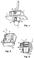
- Fig.1 is a schematic perspective view of a device according to the present invention;
- Fig.2 is a cross section view of the device shown in Fig.1, wherein the electric cable is not illustrated;
- Fig.3 is a perspective view of the first element of the device shown in Figs. 1 and 2;
- Fig.4 is a further vertical section view of the device shown in Figs. 1 and 2;
- Fig.5 is a perspective view of the assembly shown in Figs. 1 and 2, wherein the electric cable is not illustrated and the first element (1) is partially sectioned to make the second element (4) better visible;
- Figs. 6 and 7 are two perspective views of the second element.
- Reduced to its basic structure and referring to the enclosed drawings, a device according to the present invention comprises:
- a first element (1) which is provided with a central longitudinal opening (10) to allow the passage of an electric cable (2) of the type provided with a core made up of a plurality of resisting non-conductive threads (3);
- a second element (4), apt to be positioned within a corresponding seat (14) of the first element (1) so as said cable (2) passes centrally through the latter, and provided with two inner lateral surfaces (40) apt to delimit, in cooperation with the inner surface of said seat (14), a labyrinth passage for the resisting threads (3) of the cable (2): said seat (14) being a part of the opening (10) which allows the cable (2) to pass through the first element (1).
- Said first element (1) is provided, opposite to said seat (14), with a tubular tang shaped appendix (100) which, in turn, is provided with two radial appendixes (101) united to the same appendix only in correspondence of their respective bases, being surrounded by a reverse "U"-shaped cut (102).
- In this way, said appendixes (102) are allowed to elastically bend towards the inside of the appendix (100). This is particularly useful when the device is connected with a support body (5) featuring an opening (50) through which the appendix (100) of the first element (1) may be positioned, so that the appendix (100) and the said seat (14) result on opposite sides with respect to the same support (5) as shown in Fig.1, Fig.4 and Fig.5.
- The opening for the passage of the cable (2) through the first element (1) is entirely within the appendix (100) and the seat (14) of the first element.
- Said first element (1) is provided, in correspondence of said seat (14), with an opening (140) whose axis is substantially orthogonal to the opening for the cable (2); said second element (4) is provided, behind the bottom wall (41) from which said surfaces (40) emerge, with a teeth (42) destined to engage the cross opening (140) of the seat (14) when the first and the second element are assembled to lock the threads (3), so as to realize an irreversible connection of the second element with the first.
- Said surfaces (40), between which the cable (2) is destined to pass, are united, on one side, with the wall (41) from which they emerge and, on the opposite side, with two external wings (44) of the same second element (4), so that, when seen in plant view, the second element (4) has a continuous shape with a central "C" shaped portion and two "C" side portions which are on opposite sides with respect to the central portion and 180° turned with respect to the latter.
- Said surfaces (40) are substantially parallel to the external wings (44).
- According to the example shown in Figs. 5, 6 and 7, said inner surfaces (40) are united with the external wings (44) by two corresponding connecting segments or portions (46) which are made up of the same molding material of which the second element (4) is made: said connecting portions (46) being substantially orthogonal to each surface (40) and to the respective external wing (44). Said connecting portions or segments (46) are on a same side, i.e. they are substantially coplanar, and are at a preset distance from said wall (41), since between each of them and the wall (41) there is a corresponding surface (40).
- Each of said surfaces (40), the corresponding external wing and the respective connecting portion (46) cooperate to delimit an opening, which is open upwardly, downwardly and in front of the connecting portion (46), for the threads (3) to be locked.
- Furthermore, a teeth (43) is advantageously provided in correspondence of each side surface (40) of said second element (4), that is, in correspondence of the wall facing the cable (2). When the device is in operation, as in Fig.1 and Fig.4, the two tooth (43) of the second element (4) clamp the cable (2) which passes between the surfaces (40) from which the tooth (43) emerge.
- Furthermore, said surfaces (40) may be provided with respective external tooth (45), each of said tooth facing a respective external wing (44).
- The device is assembled as follows.
- The cable (2) is made to pass through the appendix (100), the seat (14) of the first element (1) and the gap between the surfaces (40) of the second element (4). Then, the resisting non-conductive threads (3) Are manually disposed to form two side bundles. Subsequently, each bundle of threads (3) is positioned between a corresponding surface (40) and the respective external wing (44) of the second element (4) and then positioned close to the external side of the same wing, as shown in Fig.4. Finally, with one hand the first element (1) is pushed towards the second element (4), and with the other hand the cable (2) is pulled in the opposite direction. Therefore, the non-conductive threads (3) are locked within the labyrinth delimited by the first and the second element (1, 4), the second element resulting positioned within the seat (14) provided by the first element. The cable (2) is clamped by the tooth (43) of the second element (4).
- The device described above may be equally advantageously used also to lock the end strands of ropes or cords.
- Practically, the construction details may vary in any equivalent way as far as the shape, dimensions, elements disposition, nature of the used materials are concerned, without nevertheless departing from the scope of the adopted solution idea and, thereby, remaining within the limits of the protection granted to the present patent for industrial invention.
Claims (8)
- Device for locking a plurality of threads (3), comprising a first and a second element (4) each of which is provided with a central opening, said first and second element cooperating to delimit a labyrinth passage for the threads (3) to be locked, characterized in that said second element (4) is provided with two surfaces (40) which are on opposite sides with respect to the respective central opening and is provided with two external wings (44) which are united to said surface (40): said surfaces (40) being united, on one side, with a bottom wall (41) of the same second element from which they emerge, and, on the opposite side, with a corresponding external wing (44) of the second element (4).
- Device according to claim 1 characterized in that said surfaces (40) are provided with respective external tooth (45) each of which faces a corresponding external wing (44) of said second element (4).
- Device according to claim 1 characterized in that said surfaces (40) of the second element (4) are provided with respective inner tooth (43).
- Device according to claim 1 characterized in that said threads (3) are resisting non-conductive threads of an electric cable (2).
- Device according to claim 1 characterized in that said threads (3) are threads or strands of a rope or cord.
- Device according to one or more of the preceding claims characterized in that said first and second element (1, 4) are provided with means (140, 42) for their reciprocal irreversible hooking.
- Device according to claim 1 characterized in that each of said surfaces (40) and the respective external wing (44) of the second element (4) are united by a connecting portion made up of the same molding material of which the second element (4) is made.
- Device according to claims 1 and 7 characterized in that said connecting portions (46) are substantially coplanar and are at a preset distance from said bottom wall (41).
Applications Claiming Priority (2)
| Application Number | Priority Date | Filing Date | Title |
|---|---|---|---|
| ITFI20030329 | 2003-12-31 | ||
| IT000329A ITFI20030329A1 (en) | 2003-12-31 | 2003-12-31 | LOCKING DEVICE. |
Publications (2)
| Publication Number | Publication Date |
|---|---|
| EP1551083A1 true EP1551083A1 (en) | 2005-07-06 |
| EP1551083B1 EP1551083B1 (en) | 2011-10-12 |
Family
ID=34566900
Family Applications (1)
| Application Number | Title | Priority Date | Filing Date |
|---|---|---|---|
| EP04028365A Expired - Lifetime EP1551083B1 (en) | 2003-12-31 | 2004-11-30 | Locking device |
Country Status (4)
| Country | Link |
|---|---|
| EP (1) | EP1551083B1 (en) |
| JP (1) | JP4348287B2 (en) |
| AT (1) | ATE528768T1 (en) |
| IT (1) | ITFI20030329A1 (en) |
Cited By (2)
| Publication number | Priority date | Publication date | Assignee | Title |
|---|---|---|---|---|
| AT13591U1 (en) * | 2012-07-24 | 2014-04-15 | Tridonic Connection Technology Gmbh & Co Kg | Strain relief device, as well as junction box and electrically operated device |
| US20250030228A1 (en) * | 2023-07-21 | 2025-01-23 | Endress+Hauser SE+Co. KG | Housing and cable clamp and device for determining and/or monitoring a process variable of a medium |
Citations (3)
| Publication number | Priority date | Publication date | Assignee | Title |
|---|---|---|---|---|
| US5345656A (en) * | 1992-02-27 | 1994-09-13 | Polytech Netting Industries, Inc. | Elastic cord lock |
| US5903959A (en) * | 1997-11-24 | 1999-05-18 | Leonardi; David P. | Fastener for retaining shoe laces and drawstrings |
| US20010017218A1 (en) * | 2000-01-26 | 2001-08-30 | Georg Linhart | Connection sleeve for a suction tube furnished with a wire protecting sheathing for strain relieved electrical conductors |
-
2003
- 2003-12-31 IT IT000329A patent/ITFI20030329A1/en unknown
-
2004
- 2004-11-30 EP EP04028365A patent/EP1551083B1/en not_active Expired - Lifetime
- 2004-11-30 AT AT04028365T patent/ATE528768T1/en not_active IP Right Cessation
- 2004-12-15 JP JP2004362659A patent/JP4348287B2/en not_active Expired - Fee Related
Patent Citations (3)
| Publication number | Priority date | Publication date | Assignee | Title |
|---|---|---|---|---|
| US5345656A (en) * | 1992-02-27 | 1994-09-13 | Polytech Netting Industries, Inc. | Elastic cord lock |
| US5903959A (en) * | 1997-11-24 | 1999-05-18 | Leonardi; David P. | Fastener for retaining shoe laces and drawstrings |
| US20010017218A1 (en) * | 2000-01-26 | 2001-08-30 | Georg Linhart | Connection sleeve for a suction tube furnished with a wire protecting sheathing for strain relieved electrical conductors |
Cited By (3)
| Publication number | Priority date | Publication date | Assignee | Title |
|---|---|---|---|---|
| AT13591U1 (en) * | 2012-07-24 | 2014-04-15 | Tridonic Connection Technology Gmbh & Co Kg | Strain relief device, as well as junction box and electrically operated device |
| DE102013213298B4 (en) | 2012-07-24 | 2024-12-05 | Tridonic Gmbh & Co Kg | strain relief device, as well as junction box and electrically operated device |
| US20250030228A1 (en) * | 2023-07-21 | 2025-01-23 | Endress+Hauser SE+Co. KG | Housing and cable clamp and device for determining and/or monitoring a process variable of a medium |
Also Published As
| Publication number | Publication date |
|---|---|
| ATE528768T1 (en) | 2011-10-15 |
| EP1551083B1 (en) | 2011-10-12 |
| ITFI20030329A1 (en) | 2005-07-01 |
| JP2005195173A (en) | 2005-07-21 |
| JP4348287B2 (en) | 2009-10-21 |
Similar Documents
| Publication | Publication Date | Title |
|---|---|---|
| US5791022A (en) | Cord locking mechanism | |
| EP3152809B1 (en) | Eletrical equipment | |
| EP1754892A1 (en) | Fan casing | |
| GB2507082A (en) | Cable Tie and Retention System | |
| BR112016022001B1 (en) | MAIN UNIT TO RETAIN A CABLE STRING TAPE | |
| CA2955051C (en) | Synthetic rope termination | |
| EP3179155B1 (en) | Illumination device | |
| JP4414776B2 (en) | Button type fixed device | |
| DE202013105149U1 (en) | wiring | |
| EP1551083B1 (en) | Locking device | |
| US7122749B2 (en) | Locking device | |
| KR101490070B1 (en) | Device for fixing a cable to a cable outlet connector | |
| ES3031974T3 (en) | Clamp for coated elevator rope | |
| DE29820606U1 (en) | Electrical stator, in particular for a compressor | |
| KR20050096066A (en) | Structure of wire grip | |
| KR200455816Y1 (en) | Wiring Holder | |
| DE102009021006B4 (en) | Device for strain relief of a plug connection of two cables connected to plugs | |
| EP1467458A2 (en) | Locking apparatus, especially for electric cables, cords or ropes | |
| WO2016203032A1 (en) | Retainer for cable raceway | |
| GB2493407A (en) | Rope ladder | |
| DE10247607B4 (en) | Vacuum cleaner with a housing in which a network-fed Sauggebläseeinrichtung is added | |
| RU118790U1 (en) | LOCK FOR PROTECTING CABLE | |
| US1596818A (en) | Rope binder | |
| US1657297A (en) | Eye structure | |
| KR20210011221A (en) | Cable hanger |
Legal Events
| Date | Code | Title | Description |
|---|---|---|---|
| PUAI | Public reference made under article 153(3) epc to a published international application that has entered the european phase |
Free format text: ORIGINAL CODE: 0009012 |
|
| AK | Designated contracting states |
Kind code of ref document: A1 Designated state(s): AT BE BG CH CY CZ DE DK EE ES FI FR GB GR HU IE IS IT LI LU MC NL PL PT RO SE SI SK TR |
|
| AX | Request for extension of the european patent |
Extension state: AL HR LT LV MK YU |
|
| 17P | Request for examination filed |
Effective date: 20050517 |
|
| AKX | Designation fees paid |
Designated state(s): AT BE BG CH CY CZ DE DK EE ES FI FR GB GR HU IE IS IT LI LU MC NL PL PT RO SE SI SK TR |
|
| REG | Reference to a national code |
Ref country code: DE Ref legal event code: R079 Ref document number: 602004034790 Country of ref document: DE Free format text: PREVIOUS MAIN CLASS: H01R0013580000 Ipc: H01B0007180000 |
|
| GRAP | Despatch of communication of intention to grant a patent |
Free format text: ORIGINAL CODE: EPIDOSNIGR1 |
|
| RIC1 | Information provided on ipc code assigned before grant |
Ipc: H01R 13/58 20060101ALN20110509BHEP Ipc: H01B 7/18 20060101AFI20110509BHEP Ipc: H02G 15/007 20060101ALI20110509BHEP |
|
| GRAS | Grant fee paid |
Free format text: ORIGINAL CODE: EPIDOSNIGR3 |
|
| GRAA | (expected) grant |
Free format text: ORIGINAL CODE: 0009210 |
|
| AK | Designated contracting states |
Kind code of ref document: B1 Designated state(s): AT BE BG CH CY CZ DE DK EE ES FI FR GB GR HU IE IS IT LI LU MC NL PL PT RO SE SI SK TR |
|
| REG | Reference to a national code |
Ref country code: GB Ref legal event code: FG4D |
|
| REG | Reference to a national code |
Ref country code: CH Ref legal event code: EP |
|
| REG | Reference to a national code |
Ref country code: IE Ref legal event code: FG4D |
|
| REG | Reference to a national code |
Ref country code: DE Ref legal event code: R096 Ref document number: 602004034790 Country of ref document: DE Effective date: 20111215 |
|
| REG | Reference to a national code |
Ref country code: NL Ref legal event code: VDEP Effective date: 20111012 |
|
| REG | Reference to a national code |
Ref country code: AT Ref legal event code: MK05 Ref document number: 528768 Country of ref document: AT Kind code of ref document: T Effective date: 20111012 |
|
| PG25 | Lapsed in a contracting state [announced via postgrant information from national office to epo] |
Ref country code: BE Free format text: LAPSE BECAUSE OF FAILURE TO SUBMIT A TRANSLATION OF THE DESCRIPTION OR TO PAY THE FEE WITHIN THE PRESCRIBED TIME-LIMIT Effective date: 20111012 Ref country code: IS Free format text: LAPSE BECAUSE OF FAILURE TO SUBMIT A TRANSLATION OF THE DESCRIPTION OR TO PAY THE FEE WITHIN THE PRESCRIBED TIME-LIMIT Effective date: 20120212 |
|
| PG25 | Lapsed in a contracting state [announced via postgrant information from national office to epo] |
Ref country code: SE Free format text: LAPSE BECAUSE OF FAILURE TO SUBMIT A TRANSLATION OF THE DESCRIPTION OR TO PAY THE FEE WITHIN THE PRESCRIBED TIME-LIMIT Effective date: 20111012 Ref country code: GR Free format text: LAPSE BECAUSE OF FAILURE TO SUBMIT A TRANSLATION OF THE DESCRIPTION OR TO PAY THE FEE WITHIN THE PRESCRIBED TIME-LIMIT Effective date: 20120113 Ref country code: NL Free format text: LAPSE BECAUSE OF FAILURE TO SUBMIT A TRANSLATION OF THE DESCRIPTION OR TO PAY THE FEE WITHIN THE PRESCRIBED TIME-LIMIT Effective date: 20111012 Ref country code: SI Free format text: LAPSE BECAUSE OF FAILURE TO SUBMIT A TRANSLATION OF THE DESCRIPTION OR TO PAY THE FEE WITHIN THE PRESCRIBED TIME-LIMIT Effective date: 20111012 Ref country code: PT Free format text: LAPSE BECAUSE OF FAILURE TO SUBMIT A TRANSLATION OF THE DESCRIPTION OR TO PAY THE FEE WITHIN THE PRESCRIBED TIME-LIMIT Effective date: 20120213 |
|
| PG25 | Lapsed in a contracting state [announced via postgrant information from national office to epo] |
Ref country code: CY Free format text: LAPSE BECAUSE OF FAILURE TO SUBMIT A TRANSLATION OF THE DESCRIPTION OR TO PAY THE FEE WITHIN THE PRESCRIBED TIME-LIMIT Effective date: 20111012 Ref country code: MC Free format text: LAPSE BECAUSE OF NON-PAYMENT OF DUE FEES Effective date: 20111130 |
|
| REG | Reference to a national code |
Ref country code: CH Ref legal event code: PL |
|
| PG25 | Lapsed in a contracting state [announced via postgrant information from national office to epo] |
Ref country code: SK Free format text: LAPSE BECAUSE OF FAILURE TO SUBMIT A TRANSLATION OF THE DESCRIPTION OR TO PAY THE FEE WITHIN THE PRESCRIBED TIME-LIMIT Effective date: 20111012 Ref country code: BG Free format text: LAPSE BECAUSE OF FAILURE TO SUBMIT A TRANSLATION OF THE DESCRIPTION OR TO PAY THE FEE WITHIN THE PRESCRIBED TIME-LIMIT Effective date: 20120112 Ref country code: DK Free format text: LAPSE BECAUSE OF FAILURE TO SUBMIT A TRANSLATION OF THE DESCRIPTION OR TO PAY THE FEE WITHIN THE PRESCRIBED TIME-LIMIT Effective date: 20111012 Ref country code: CH Free format text: LAPSE BECAUSE OF NON-PAYMENT OF DUE FEES Effective date: 20111130 Ref country code: EE Free format text: LAPSE BECAUSE OF FAILURE TO SUBMIT A TRANSLATION OF THE DESCRIPTION OR TO PAY THE FEE WITHIN THE PRESCRIBED TIME-LIMIT Effective date: 20111012 Ref country code: CZ Free format text: LAPSE BECAUSE OF FAILURE TO SUBMIT A TRANSLATION OF THE DESCRIPTION OR TO PAY THE FEE WITHIN THE PRESCRIBED TIME-LIMIT Effective date: 20111012 Ref country code: LI Free format text: LAPSE BECAUSE OF NON-PAYMENT OF DUE FEES Effective date: 20111130 |
|
| PLBE | No opposition filed within time limit |
Free format text: ORIGINAL CODE: 0009261 |
|
| STAA | Information on the status of an ep patent application or granted ep patent |
Free format text: STATUS: NO OPPOSITION FILED WITHIN TIME LIMIT |
|
| REG | Reference to a national code |
Ref country code: IE Ref legal event code: MM4A |
|
| PG25 | Lapsed in a contracting state [announced via postgrant information from national office to epo] |
Ref country code: PL Free format text: LAPSE BECAUSE OF FAILURE TO SUBMIT A TRANSLATION OF THE DESCRIPTION OR TO PAY THE FEE WITHIN THE PRESCRIBED TIME-LIMIT Effective date: 20111012 Ref country code: RO Free format text: LAPSE BECAUSE OF FAILURE TO SUBMIT A TRANSLATION OF THE DESCRIPTION OR TO PAY THE FEE WITHIN THE PRESCRIBED TIME-LIMIT Effective date: 20111012 |
|
| 26N | No opposition filed |
Effective date: 20120713 |
|
| GBPC | Gb: european patent ceased through non-payment of renewal fee |
Effective date: 20120112 |
|
| PG25 | Lapsed in a contracting state [announced via postgrant information from national office to epo] |
Ref country code: GB Free format text: LAPSE BECAUSE OF NON-PAYMENT OF DUE FEES Effective date: 20120112 Ref country code: IE Free format text: LAPSE BECAUSE OF NON-PAYMENT OF DUE FEES Effective date: 20111130 |
|
| REG | Reference to a national code |
Ref country code: DE Ref legal event code: R097 Ref document number: 602004034790 Country of ref document: DE Effective date: 20120713 |
|
| PG25 | Lapsed in a contracting state [announced via postgrant information from national office to epo] |
Ref country code: AT Free format text: LAPSE BECAUSE OF FAILURE TO SUBMIT A TRANSLATION OF THE DESCRIPTION OR TO PAY THE FEE WITHIN THE PRESCRIBED TIME-LIMIT Effective date: 20111012 |
|
| PG25 | Lapsed in a contracting state [announced via postgrant information from national office to epo] |
Ref country code: ES Free format text: LAPSE BECAUSE OF FAILURE TO SUBMIT A TRANSLATION OF THE DESCRIPTION OR TO PAY THE FEE WITHIN THE PRESCRIBED TIME-LIMIT Effective date: 20120123 |
|
| PGFP | Annual fee paid to national office [announced via postgrant information from national office to epo] |
Ref country code: DE Payment date: 20130130 Year of fee payment: 9 Ref country code: FR Payment date: 20130205 Year of fee payment: 9 |
|
| PG25 | Lapsed in a contracting state [announced via postgrant information from national office to epo] |
Ref country code: LU Free format text: LAPSE BECAUSE OF NON-PAYMENT OF DUE FEES Effective date: 20111130 |
|
| PG25 | Lapsed in a contracting state [announced via postgrant information from national office to epo] |
Ref country code: FI Free format text: LAPSE BECAUSE OF FAILURE TO SUBMIT A TRANSLATION OF THE DESCRIPTION OR TO PAY THE FEE WITHIN THE PRESCRIBED TIME-LIMIT Effective date: 20111012 |
|
| PG25 | Lapsed in a contracting state [announced via postgrant information from national office to epo] |
Ref country code: IT Free format text: LAPSE BECAUSE OF NON-PAYMENT OF DUE FEES Effective date: 20121130 |
|
| PG25 | Lapsed in a contracting state [announced via postgrant information from national office to epo] |
Ref country code: TR Free format text: LAPSE BECAUSE OF FAILURE TO SUBMIT A TRANSLATION OF THE DESCRIPTION OR TO PAY THE FEE WITHIN THE PRESCRIBED TIME-LIMIT Effective date: 20111012 |
|
| PG25 | Lapsed in a contracting state [announced via postgrant information from national office to epo] |
Ref country code: HU Free format text: LAPSE BECAUSE OF FAILURE TO SUBMIT A TRANSLATION OF THE DESCRIPTION OR TO PAY THE FEE WITHIN THE PRESCRIBED TIME-LIMIT Effective date: 20111012 |
|
| REG | Reference to a national code |
Ref country code: FR Ref legal event code: ST Effective date: 20140731 |
|
| PG25 | Lapsed in a contracting state [announced via postgrant information from national office to epo] |
Ref country code: DE Free format text: LAPSE BECAUSE OF NON-PAYMENT OF DUE FEES Effective date: 20140603 |
|
| REG | Reference to a national code |
Ref country code: DE Ref legal event code: R119 Ref document number: 602004034790 Country of ref document: DE Effective date: 20140603 |
|
| PG25 | Lapsed in a contracting state [announced via postgrant information from national office to epo] |
Ref country code: FR Free format text: LAPSE BECAUSE OF NON-PAYMENT OF DUE FEES Effective date: 20131202 |