EP1551015A2 - Optical pick-up device capable of correcting spherical aberration - Google Patents
Optical pick-up device capable of correcting spherical aberration Download PDFInfo
- Publication number
- EP1551015A2 EP1551015A2 EP04030717A EP04030717A EP1551015A2 EP 1551015 A2 EP1551015 A2 EP 1551015A2 EP 04030717 A EP04030717 A EP 04030717A EP 04030717 A EP04030717 A EP 04030717A EP 1551015 A2 EP1551015 A2 EP 1551015A2
- Authority
- EP
- European Patent Office
- Prior art keywords
- mirror
- light
- circular
- prism
- piezoelectric element
- Prior art date
- Legal status (The legal status is an assumption and is not a legal conclusion. Google has not performed a legal analysis and makes no representation as to the accuracy of the status listed.)
- Withdrawn
Links
- 230000003287 optical effect Effects 0.000 title claims description 50
- 230000004075 alteration Effects 0.000 title description 34
- 230000005540 biological transmission Effects 0.000 claims abstract description 15
- 230000014509 gene expression Effects 0.000 description 7
- NCGICGYLBXGBGN-UHFFFAOYSA-N 3-morpholin-4-yl-1-oxa-3-azonia-2-azanidacyclopent-3-en-5-imine;hydrochloride Chemical compound Cl.[N-]1OC(=N)C=[N+]1N1CCOCC1 NCGICGYLBXGBGN-UHFFFAOYSA-N 0.000 description 4
- 239000004973 liquid crystal related substance Substances 0.000 description 2
- 230000002093 peripheral effect Effects 0.000 description 2
- 238000000034 method Methods 0.000 description 1
Images



Classifications
-
- G—PHYSICS
- G11—INFORMATION STORAGE
- G11B—INFORMATION STORAGE BASED ON RELATIVE MOVEMENT BETWEEN RECORD CARRIER AND TRANSDUCER
- G11B7/00—Recording or reproducing by optical means, e.g. recording using a thermal beam of optical radiation by modifying optical properties or the physical structure, reproducing using an optical beam at lower power by sensing optical properties; Record carriers therefor
- G11B7/12—Heads, e.g. forming of the optical beam spot or modulation of the optical beam
- G11B7/135—Means for guiding the beam from the source to the record carrier or from the record carrier to the detector
- G11B7/1392—Means for controlling the beam wavefront, e.g. for correction of aberration
- G11B7/13925—Means for controlling the beam wavefront, e.g. for correction of aberration active, e.g. controlled by electrical or mechanical means
- G11B7/13927—Means for controlling the beam wavefront, e.g. for correction of aberration active, e.g. controlled by electrical or mechanical means during transducing, e.g. to correct for variation of the spherical aberration due to disc tilt or irregularities in the cover layer thickness
-
- G—PHYSICS
- G11—INFORMATION STORAGE
- G11B—INFORMATION STORAGE BASED ON RELATIVE MOVEMENT BETWEEN RECORD CARRIER AND TRANSDUCER
- G11B7/00—Recording or reproducing by optical means, e.g. recording using a thermal beam of optical radiation by modifying optical properties or the physical structure, reproducing using an optical beam at lower power by sensing optical properties; Record carriers therefor
- G11B7/12—Heads, e.g. forming of the optical beam spot or modulation of the optical beam
- G11B7/135—Means for guiding the beam from the source to the record carrier or from the record carrier to the detector
- G11B7/1359—Single prisms
-
- G—PHYSICS
- G11—INFORMATION STORAGE
- G11B—INFORMATION STORAGE BASED ON RELATIVE MOVEMENT BETWEEN RECORD CARRIER AND TRANSDUCER
- G11B7/00—Recording or reproducing by optical means, e.g. recording using a thermal beam of optical radiation by modifying optical properties or the physical structure, reproducing using an optical beam at lower power by sensing optical properties; Record carriers therefor
- G11B7/12—Heads, e.g. forming of the optical beam spot or modulation of the optical beam
- G11B7/135—Means for guiding the beam from the source to the record carrier or from the record carrier to the detector
- G11B7/1362—Mirrors
Definitions
- the present invention relates generally to optical pickup devices and particularly to optical pickup devices having a function correcting spherical aberration.
- Compact disks CDs
- DVD digital versatile disks
- apparatuses including an optical pickup device to optically read the information from the optical disks.
- a source of light emits a laser beam of light which is in turn reflected by a mirror and gathered by an objective lens to illuminate an optical disk's recording surface on a desired track.
- the track reflects and thus returns the light which is in turn detected by a photodetector to read the track's information.
- the light gathered by the objective lens can provide spherical aberration.
- Spherical aberration means that, of rays focused by the objective lens, a ray passing through a portion of the lens remote from the optical axis, or the lens's peripheral portion, and a ray passing close to the optical axis, or the lens's center, are focused at different locations.
- an optical disk cannot have its information satisfactorily reproduced.
- the objective lens is designed to correct spherical aberration for a thickness of an optical disk predetermined. If the optical disk is not uniform in thickness, however, and an amount of correction does not match, spherical aberration is introduced. Furthermore, if the optical disk has a recording layer formed of multiple layers, and a jump is made to a different layer, an amount of correction does not match, and spherical aberration is introduced.
- Such spherical aberration is prevented for example by a method employing a liquid crystal device to modulate a phase corresponding to the spherical aberration, as disclosed in Japanese Patent Laying-Open No. 2003-141771.
- the present invention contemplates an optical pickup device that can have a simplified structure to reduce spherical aberration.
- the present invention in one aspect provides an optical pickup device allowing a laser beam of light emitted from a source of a laser beam of light to be reflected by a mirror to provide a reflection of light which is in turn focused by an objective lens on an optical storage medium
- the optical pickup device including: a circular mirror reflecting the laser beam of light; and a mirror actuator including a piezoelectric element having a circular surface bonded to a circular rear surface of the mirror such that the center of the circular surface of the piezoelectric element and that of the circular rear surface of the mirror match, the piezoelectric element receiving a potential to cause the circular surface bonded to the mirror to expand/contract radially around 360 degrees by a uniform ratio to allow the mirror to have a surface modified in geometry, the mirror having a mirror surface provided with a transmission film having an index of refraction of at least one.
- the present invention in another aspect provides an optical pickup device allowing a laser beam of light emitted from a source of a laser beam of light to be reflected by a mirror to provide a reflection of light in turn focused by an objective lens on an optical storage medium
- the optical pickup device including: a circular mirror reflecting the laser beam of light; a prism arranged opposite a mirror surface of the mirror; and a mirror actuator including a piezoelectric element having a circular surface bonded to a circular rear surface of the mirror such that the center of the circular surface of the piezoelectric element and that of the circular rear surface of the mirror match, the piezoelectric element receiving a potential to cause the circular surface bonded to the mirror to expand/contract radially around 360 degrees by a uniform ratio to allow the mirror to have a surface modified in geometry, and if a beam of light emitted from the source must be directed in a direction allowing an angle ⁇ 4 + ⁇ 12 relative to a direction of incidence of the beam to provide the beam to the objective lens, the prism and the
- the present optical pickup device can have a simplified structure to reduce spherical aberration.
- the present embodiment relates to an optical pickup device including a turning/aberration correction mirror provided with a transmission film.
- Fig. 1 shows a main portion of an optical system of the pickup device.
- the optical pickup device includes a source of light 1, a collimator 2, a polarizing beam splitter 3, a circular, turning/aberration correction mirror 4, an objective lens 5, a cylindrical lens 7, a photodetector 8, and a mirror actuator 10.
- the source of light 1 emits a beam 13.
- Collimator 2 collimates beam 13 into a collimated beam of light 11.
- Mirror 4 turns the collimated beam of light 11 in a direction, i.e., reflects beam 11 toward an optical disk 6 to provide a reflection of light 12.
- Objective lens 5 allows the reflection of light 12 to illuminate optical disk 6 on an information recording surface.
- the information recording surface has a bit train, which modulates the reflection of light in optical intensity.
- the reflection of light thus modulated then passes through objective lens 5 and is reflected by mirror 4 and then polarizing beam splitter 3 and converged by cylindrical lens 7 and thus input to photodetector 8.
- Photodetector 8 receives the light, which is used to reproduce information of optical disk 6 and control objective lens 5 to focus and track appropriately.
- a control circuit (not shown) separates the light incident on photodetector 8 into light of a center portion and that of a peripheral portion and detects their respective focus positions to detect an amount of spherical aberration.
- the control circuit is driven by the detected amount of spherical aberration to control mirror actuator 10, which supports mirror 4, to modify the mirror 4 mirror surface in geometry to reduce the amount of spherical aberration.
- Fig. 2A shows an optical path of the reflection of light 12 provided when mirror 4 has a mirror surface with a typical or flat geometry. As shown in the figure, spherical aberration has been introduced.
- Fig. 2B shows an optical path of the reflection of light 12 provided when mirror 4 has its mirror surface modified in geometry. As shown in the figure, the mirror surface is modified in geometry to reduce an amount of spherical aberration.
- Fig. 3 shows a structure of mirror actuator 10.
- mirror actuator 10 includes a piezoelectric element 21, a branch 22 supporting piezoelectric element 21, and a fixture 23.
- Piezoelectric element 21 is bonded on a rear surface of mirror 4.
- the surface of piezoelectric element 21 that is bonded to the rear surface of mirror 4 is a circle, and the circle's center matches that of the rear, circular surface of the mirror.
- Piezoelectric element 21 has its thickness in a direction perpendicular to the mirror surface.
- piezoelectric element 21 When piezoelectric element 21 has potential applied thereon, piezoelectric element 21 expands/contracts. More specifically, when piezoelectric element 21 receives positive potential, piezoelectric element 21 has the circular surface bonded to mirror 4 expanding radially around 360 degrees by a uniform ratio, as indicated in Fig. 3 by an arrow (1). As mirror 4 is bonded to piezoelectric element 21, mirror 4 flexes to concave, and the reflection of light 12 is thus converged.
- piezoelectric element 21 when piezoelectric element 21 receives negative potential, then as indicated in Fig. 3 by an arrow (2), piezoelectric element 21 has the circular surface bonded to mirror 4 contracting radially around 360 degrees by a uniform ratio. As mirror 4 is bonded to piezoelectric element 21, mirror 4 flexes to protrude, and the reflection of light 12 is thus diverged.
- mirror 4 has a mirror surface receiving the collimated beam of light 11 in an elliptical spot.
- a mirror angle refers to an angle of the collimated beam of light 11 incident on the mirror 4 mirror surface having a typical geometry.
- a tangential direction is a direction parallel to the mirror surface of mirror 4 in normal condition and connecting locations on the mirror that receive rays of light closest to and remotest from the optical disk 6 surface.
- a radial direction is a direction parallel to the mirror surface of mirror 4 in normal condition and perpendicular to the tangential direction.
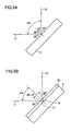
- spherical aberration can appropriately be reduced in amount by allowing the turning/aberration correction mirror 4 mirror surface to receive the collimated beam of light 11 at an angle as close to a vertical angle as possible (i.e., at an angle allowing an incident angle to be close to 0°) by providing the mirror 4 mirror surface with a transmission film 20 having as high an index of refraction as possible of at least one.
- Fig. 5B shows an optical path of the collimated beam of light 11 and the reflection of light 12 provided when mirror 4 has a mirror surface provided with transmission film 20 having an index of refraction of 1.7.
- the refraction of light 13 is reflected by the mirror 4 mirror surface.
- the angles of incidence and reflection are ⁇ ( ⁇ ⁇ ).
- a reflection of light 14 is incident on the transmission film 20 surface at angle ⁇ and refracted through the same surface to provide the reflection of light 12 which is in turn incident on objective lens 15.
- the transmission film having an index of refraction of at least one that is provided on the mirror 4 mirror surface can provide a reduced angle of incidence of light on the mirror surface so that mirror 4 can receive light in a direction close to a perpendicular direction.
- the present embodiment provides an optical pickup device including turning/aberration correction mirror 4 having a mirror surface provided with a transmission film having an index of refraction of at least one so that if mirror 4 deformed to correct spherical aberration has a mirror surface with equal radii of curvature in the tangential and radial directions, an appropriately reduced amount of spherical aberration can be achieved.
- the present embodiment relates to an optical pickup device including a prism arranged opposite a mirror surface of a turning/aberration correction mirror.
- the present embodiment's optical pickup device differs from the first embodiment's optical pickup device shown in Fig. 1 in that turning/aberration correction mirror 4 does not have a mirror surface provided with transmission film 20 but rather has a mirror surface opposite a prism 30.
- Fig. 6 shows an arrangement of prism 30 and mirror 4.
- prism 30 is formed of BK7 and has an index of refraction n 1 , and is arranged opposite the mirror 4 surface (or mirror surface).
- the prism 30 front and rear surfaces and the mirror 4 mirror surface form angles ⁇ 1 , ⁇ 2 and ⁇ 3 , respectively, relative to a direction perpendicular to the collimated beam of light 11 for the sake of illustration.
- the angle formed by the collimated beam of light 11 and the reflection of light 12 is not limited to 90° for the sake of illustration.
- ⁇ 6 ⁇ 5 + ( ⁇ 2 - ⁇ 1 )
- ⁇ 7 sin -1 (n 1 ⁇ sin ⁇ 6 )
- ⁇ 10 sin -1 (sin ⁇ 9 /n 1 )
- ⁇ 11 ⁇ 10 + ( ⁇ 2 - ⁇ 1 )
- ⁇ 12 sin -1 (n1 ⁇ sin ⁇ 11 )
- the collimated beam of light 11 must be directed in a direction allowing an angle of ( ⁇ 4 + ⁇ 12 ) relative to a direction of incidence of the collimated beam of light 11 to provide the collimated beam of light 11 to objective lens 5, setting an inclination of prism 30 (associated with ⁇ 1 and ⁇ 2 ), that of turning/aberration correction mirror 4 (associated with ⁇ 3 ), and the prism 30 index of refraction (n 1 ) and geometry (associated with ⁇ 1 and ⁇ 2 ) as appropriate so that the prism 30 front and rear surfaces receives and emanates light at the angles of incidence ⁇ 4 and refraction ⁇ 12 , respectively, and the relationship ( ⁇ 4 + ⁇ 12 ) > (2 ⁇ ⁇ 8 ) is also satisfied, allows a smaller angle of incidence on mirror 4 than when prism 30 is absent.
- the present embodiment provides an optical pickup device including turning/aberration correction mirror 4 having a mirror surface opposite prism 30 having an appropriate index of refraction and an appropriate geometry and positioned as appropriate so that if mirror 4 deformed to correct spherical aberration has a mirror surface with a uniform radius of curvature in its tangential and radial directions, an appropriately reduced amount of spherical aberration can still be achieved.
Landscapes
- Physics & Mathematics (AREA)
- Optics & Photonics (AREA)
- Optical Head (AREA)
- Mechanical Light Control Or Optical Switches (AREA)
Abstract
Description
Claims (2)
- An optical pickup device allowing a laser beam of light (13) emitted from a source of a laser beam of light (1) to be reflected by a mirror (4) to provide a reflection of light (12) in turn focused by an objective lens (5) on an optical storage medium (6), comprising:a circular mirror (4) reflecting the laser beam of light (13); anda mirror actuator (10) including a piezoelectric element (21) having a circular surface bonded to a circular rear surface of said mirror (4) such that a center of said circular surface of said piezoelectric element and that of said circular rear surface of said mirror (4) match, said piezoelectric element (21) receiving a potential to cause said circular surface bonded to said mirror to expand/contract radially around 360 degrees by a uniform ratio to allow said mirror (4) to have a surface modified in geometry, said mirror (4) having a mirror surface provided with a transmission film (20) having an index of refraction of at least one.
- An optical pickup device allowing a laser beam of light (13) emitted from a source of a laser beam of light (1) to be reflected by a mirror (4) to provide a reflection of light (12) in turn focused by an objective lens (5) on an optical storage medium (6), comprising:a circular mirror (4) reflecting said laser beam of light (13);a prism (3) arranged opposite a mirror surface of said mirror (4); anda mirror actuator (10) including a piezoelectric element (21) having a circular surface bonded to a circular rear surface of said mirror (4) such that a center of said circular surface of said piezoelectric element and that of said circular rear surface of said mirror (4) match, said piezoelectric element (21) receiving a potential to cause said circular surface bonded to said mirror to expand/contract radially around 360 degrees by a uniform ratio to allow said mirror (4) to have a surface modified in geometry, if a beam of light emitted from said source (1) must be directed in a direction allowing an angle 4 + 12 relative to a direction of incidence of said beam to provide said beam to said objective lens (5), said prism (30) and said mirror (4) being inclined and said prism (30) having an index of refraction and a geometry, set to establish (4 + 12) > (2 × 8), where 4 represents an angle of incidence of light on a surface of said prism (30) farther from said mirror surface of said mirror (4), 12 represents an angle of refraction of light emanating from said surface of said prism (30) farther from said mirror surface of said mirror (4), and 8 represents an angle of incidence on said mirror (4) of light emanating from a surface of said prism (30) closer to said mirror surface of said mirror (4).
Applications Claiming Priority (2)
| Application Number | Priority Date | Filing Date | Title |
|---|---|---|---|
| JP2004000555 | 2004-01-05 | ||
| JP2004000555A JP2005196842A (en) | 2004-01-05 | 2004-01-05 | Optical pickup device |
Publications (2)
| Publication Number | Publication Date |
|---|---|
| EP1551015A2 true EP1551015A2 (en) | 2005-07-06 |
| EP1551015A3 EP1551015A3 (en) | 2008-01-23 |
Family
ID=34567577
Family Applications (1)
| Application Number | Title | Priority Date | Filing Date |
|---|---|---|---|
| EP04030717A Withdrawn EP1551015A3 (en) | 2004-01-05 | 2004-12-23 | Optical pick-up device capable of correcting spherical aberration |
Country Status (4)
| Country | Link |
|---|---|
| US (1) | US20050146998A1 (en) |
| EP (1) | EP1551015A3 (en) |
| JP (1) | JP2005196842A (en) |
| CN (1) | CN1306501C (en) |
Cited By (2)
| Publication number | Priority date | Publication date | Assignee | Title |
|---|---|---|---|---|
| WO2006030371A1 (en) * | 2004-09-16 | 2006-03-23 | Koninklijke Philips Electronics N.V. | Optical scanning device |
| EP2139224A1 (en) * | 2008-06-23 | 2009-12-30 | SMR PATENTS S.à.r.l. | Imaging system, sensor unit with an imaging system and vehicle mirror comprising an imaging system |
Families Citing this family (1)
| Publication number | Priority date | Publication date | Assignee | Title |
|---|---|---|---|---|
| CN113474882A (en) * | 2019-02-27 | 2021-10-01 | 京瓷株式会社 | Package for mounting optical element, electronic device, and electronic module |
Family Cites Families (11)
| Publication number | Priority date | Publication date | Assignee | Title |
|---|---|---|---|---|
| FR2462758A1 (en) * | 1979-08-03 | 1981-02-13 | Thomson Csf | OPTICAL DEVICE FOR ACCESSING A TRACK RUN BY AN INFORMATION CARRIER AND OPTICAL MEMORY SYSTEM COMPRISING SUCH A DEVICE |
| US4761774A (en) * | 1985-05-30 | 1988-08-02 | Matsushita Electric Industrial Co., Ltd. | Optical disc drive apparatus |
| JPH0670857B2 (en) * | 1989-07-05 | 1994-09-07 | 三菱電機株式会社 | Optical information recording / reproducing device |
| JPH08279655A (en) * | 1995-04-04 | 1996-10-22 | Sony Corp | Compound optics |
| TW301719B (en) * | 1996-09-20 | 1997-04-01 | Ind Tech Res Inst | The beam shaper device |
| JPH11120601A (en) * | 1997-10-17 | 1999-04-30 | Fujitsu Ten Ltd | Optical pickup |
| US6304526B1 (en) * | 1998-03-12 | 2001-10-16 | Matsushita Electric Industrial Co., Ltd. | Optical head |
| TW442783B (en) * | 1999-07-09 | 2001-06-23 | Ind Tech Res Inst | Folding mirror |
| JP4228476B2 (en) * | 1999-07-28 | 2009-02-25 | コニカミノルタオプト株式会社 | Optical head device |
| US6496453B2 (en) * | 2000-03-27 | 2002-12-17 | Matsushita Electric Industrial Co., Ltd. | Optical pickup |
| EP1197767A3 (en) * | 2000-10-11 | 2004-12-22 | Olympus Optical Co., Ltd. | Optical apparatus comprising variable mirror |
-
2004
- 2004-01-05 JP JP2004000555A patent/JP2005196842A/en active Pending
- 2004-12-23 EP EP04030717A patent/EP1551015A3/en not_active Withdrawn
- 2004-12-30 US US11/026,271 patent/US20050146998A1/en not_active Abandoned
-
2005
- 2005-01-05 CN CNB2005100090831A patent/CN1306501C/en not_active Expired - Fee Related
Cited By (3)
| Publication number | Priority date | Publication date | Assignee | Title |
|---|---|---|---|---|
| WO2006030371A1 (en) * | 2004-09-16 | 2006-03-23 | Koninklijke Philips Electronics N.V. | Optical scanning device |
| US7881165B2 (en) | 2004-09-16 | 2011-02-01 | Koninklijke Philips Electronics N.V. | Optical scanning device with compact spherical aberration compensation |
| EP2139224A1 (en) * | 2008-06-23 | 2009-12-30 | SMR PATENTS S.à.r.l. | Imaging system, sensor unit with an imaging system and vehicle mirror comprising an imaging system |
Also Published As
| Publication number | Publication date |
|---|---|
| CN1637888A (en) | 2005-07-13 |
| CN1306501C (en) | 2007-03-21 |
| EP1551015A3 (en) | 2008-01-23 |
| JP2005196842A (en) | 2005-07-21 |
| US20050146998A1 (en) | 2005-07-07 |
Similar Documents
| Publication | Publication Date | Title |
|---|---|---|
| KR100348883B1 (en) | Optical pick up for suppressing astigmatism | |
| JPH1064103A (en) | Optical pickup device | |
| US7230905B2 (en) | Optical pickup using two-wavelength light source module and method for correcting position difference | |
| JPH0950643A (en) | Optical regenerator | |
| US7764587B2 (en) | Optical pickup apparatus | |
| US20050146998A1 (en) | Optical pickup device capable of correcting spherical aberration | |
| US7283434B2 (en) | Optical pickup device capable of correcting spherical aberration | |
| JP2000268391A (en) | Optical pickup device | |
| EP1530206A2 (en) | Optical head device having deformable reflecting mirror | |
| WO2007119410A1 (en) | Optical head and optical disk device | |
| JPH0434740A (en) | Optical head | |
| JPH09138967A (en) | Optical pickup device | |
| KR19990071790A (en) | Apparatus for writing to and / or reading from an optical record carrier having a different structure | |
| US7164626B2 (en) | Optical pickup using a wedge type beam splitter | |
| KR100421011B1 (en) | Optical pickup comprising a polygon prism and method of compensating optical axes using the same | |
| KR100433523B1 (en) | Optical pickup apparatus and method of compensating of optical axes using the same | |
| US7447136B2 (en) | Optical pickup and optical disc apparatus | |
| JP2005063572A (en) | Optical pickup and optical disk playback device | |
| KR100403596B1 (en) | Optic pickup apparatus comprising a right-angled triangle beam splitter and method of compensating optic axes using the same | |
| US20030043724A1 (en) | Optical pickup apparatus having beam splitter on which hologram is formed and method of compensating for deviation between optical axes using the optical pickup apparatus | |
| JP2002040323A (en) | Optical pickup device | |
| CN1280357A (en) | Optic reader capable of stably tracing | |
| JPH11250485A (en) | Optical pickup device | |
| CN102194480A (en) | Optical pickup device | |
| JPH1021579A (en) | Optical pickup |
Legal Events
| Date | Code | Title | Description |
|---|---|---|---|
| PUAI | Public reference made under article 153(3) epc to a published international application that has entered the european phase |
Free format text: ORIGINAL CODE: 0009012 |
|
| AK | Designated contracting states |
Kind code of ref document: A2 Designated state(s): AT BE BG CH CY CZ DE DK EE ES FI FR GB GR HU IE IS IT LI LT LU MC NL PL PT RO SE SI SK TR |
|
| AX | Request for extension of the european patent |
Extension state: AL BA HR LV MK YU |
|
| PUAL | Search report despatched |
Free format text: ORIGINAL CODE: 0009013 |
|
| AK | Designated contracting states |
Kind code of ref document: A3 Designated state(s): AT BE BG CH CY CZ DE DK EE ES FI FR GB GR HU IE IS IT LI LT LU MC NL PL PT RO SE SI SK TR |
|
| AX | Request for extension of the european patent |
Extension state: AL BA HR LV MK YU |
|
| AKX | Designation fees paid | ||
| STAA | Information on the status of an ep patent application or granted ep patent |
Free format text: STATUS: THE APPLICATION IS DEEMED TO BE WITHDRAWN |
|
| 18D | Application deemed to be withdrawn |
Effective date: 20080724 |
|
| REG | Reference to a national code |
Ref country code: DE Ref legal event code: 8566 |