EP1550627A1 - Clamp actuator system - Google Patents
Clamp actuator system Download PDFInfo
- Publication number
- EP1550627A1 EP1550627A1 EP04257671A EP04257671A EP1550627A1 EP 1550627 A1 EP1550627 A1 EP 1550627A1 EP 04257671 A EP04257671 A EP 04257671A EP 04257671 A EP04257671 A EP 04257671A EP 1550627 A1 EP1550627 A1 EP 1550627A1
- Authority
- EP
- European Patent Office
- Prior art keywords
- clamp
- compiled set
- compiled
- edge
- substrate
- Prior art date
- Legal status (The legal status is an assumption and is not a legal conclusion. Google has not performed a legal analysis and makes no representation as to the accuracy of the status listed.)
- Granted
Links
Images




Classifications
-
- B—PERFORMING OPERATIONS; TRANSPORTING
- B65—CONVEYING; PACKING; STORING; HANDLING THIN OR FILAMENTARY MATERIAL
- B65H—HANDLING THIN OR FILAMENTARY MATERIAL, e.g. SHEETS, WEBS, CABLES
- B65H9/00—Registering, e.g. orientating, articles; Devices therefor
- B65H9/10—Pusher and like movable registers; Pusher or gripper devices which move articles into registered position
- B65H9/101—Pusher and like movable registers; Pusher or gripper devices which move articles into registered position acting on the edge of the article
-
- B—PERFORMING OPERATIONS; TRANSPORTING
- B65—CONVEYING; PACKING; STORING; HANDLING THIN OR FILAMENTARY MATERIAL
- B65H—HANDLING THIN OR FILAMENTARY MATERIAL, e.g. SHEETS, WEBS, CABLES
- B65H29/00—Delivering or advancing articles from machines; Advancing articles to or into piles
- B65H29/26—Delivering or advancing articles from machines; Advancing articles to or into piles by dropping the articles
-
- B—PERFORMING OPERATIONS; TRANSPORTING
- B65—CONVEYING; PACKING; STORING; HANDLING THIN OR FILAMENTARY MATERIAL
- B65H—HANDLING THIN OR FILAMENTARY MATERIAL, e.g. SHEETS, WEBS, CABLES
- B65H31/00—Pile receivers
- B65H31/32—Auxiliary devices for receiving articles during removal of a completed pile
-
- B—PERFORMING OPERATIONS; TRANSPORTING
- B65—CONVEYING; PACKING; STORING; HANDLING THIN OR FILAMENTARY MATERIAL
- B65H—HANDLING THIN OR FILAMENTARY MATERIAL, e.g. SHEETS, WEBS, CABLES
- B65H33/00—Forming counted batches in delivery pile or stream of articles
- B65H33/06—Forming counted batches in delivery pile or stream of articles by displacing articles to define batches
- B65H33/08—Displacing whole batches, e.g. forming stepped piles
Definitions
- This invention generally relates to systems and methods for clamping and transferring compiled substrates.
- the compilation or collection of flexible substrates including sheets of paper, plastic, and/or the like, is desirable in various fields of production including individual use, publication, imaging, and/or the like.
- To maintain proper alignment, or registration, of the substrates is desirable to provide an organized, neatly stacked compilation that can be transferred without unwanted creasing and/or scattering of the substrates.
- U.S. Patents are noted by way of example: U.S. Patent 4,017,066; U.S. Patent 4,589,645; U.S. Patent 4,637,598; U.S. Patent 4,934,683; U.S. Patent 5,026,034; U.S. Patent 5,088,714; U.S. Patent 5,169,135; U.S. Patent 5,915,688; and U.S. patent 5,649,695.
- the trail edge of the compiled set is only supported from underneath the bottom substrate of the set.
- the trail edges of the substrates in the compiled set still become misaligned in various directions.
- the lead edge of the compiled set is not bound with a staple, adhesive, fastener or the like, the potential exists for even greater misalignment.
- This invention provides systems and methods for transferring compiled sets of substrates while reducing the misalignment of the substrates in the compiled sets.
- this invention provides a clamping and transferring system approach that helps reduce the footprint or lateral space requirement to help maximize the efficiency of space used in the finishing devices, i.e. devices which can provide pre-collated sets, compiled sets, bound sets and/or the like, especially in high volume finishing applications that may or may not have multiple discharge paths.
- this invention provides a clamping and transferring system that can handle substrates of various materials, weights and sizes.
- this invention provides a clamping and transferring system that helps reduce the weight of a tamper device and helps increase the efficiency of the alignment of substrates in the compiled set, especially in high speed applications.
- this invention provides a clamping and transferring system approach that provides a force on a cable to clamp substrates in the compiled set.
- this invention provides systems and methods for clamping compiled sets of substrate to reduce the scattering of substrates in the compiled set.
- this invention provides systems and methods for clamping compiled sets of substrate to reduce the scattering of substrates in the compiled set.
- this invention provides system and methods for clamping compiled sets of substrate to ensure that the substrates of each set always remain controlled. That is, by clamping, and therefore positively controlling, the trail edge of the compiled set during the drop and/or transfer from a compile position to the stack, stacking tray, platform or the like, scattering of the substrates in the compiled set is reduced.
- substrates in a compiled set can be transferred while being clamped.
- substrates in a compiled set can be transferred to a stacking tray in a controlled manner.
- the clamp actuator system includes an actuator, a cable and a tamper device.
- the tamper device may include a platform and a clamp mechanism.
- the clamp mechanism may include a substrate support device and a clamp assembly to clamp a trail edge of a compiled set to reduce scattering of the substrates in the compiled set.
- the clamp mechanism is preferably lightweight to reduce the weight of a tamper device and help increase the efficiency of the alignment of substrates.
- the clamp assembly can be retracted and extended.
- the clamp assembly can be retracted to compile a set of substrates and then extended to transfer the compiled set.
- the actuator provides a force on the cable to clamp substrates in the compiled set.
- the actuator exerts a force on the cable, and preferably the clamp assembly moves from a retracted position to an extended position, the clamp assembly exerts a substantially constant amount of force on the clamped compiled set.
- the substrates in a compiled set can be transferred to a stacking tray in a controlled manner.
- Various exemplary embodiments of the systems and methods according to this invention enable the clamping and transfer of flexible substrates in an image-forming system, substrate compilation system, or the like, to be advanced through the use of a clamp actuator system.
- Mechanisms and techniques used in the clamp actuator system according to this invention provide a combination of tamping, clamping and transporting.
- Fig. 1 is a block diagram of one exemplary embodiment of a substrate-compiling system 100 in which a substrate may need to be registered and transported.
- the substrate-compiling system 100 includes a substrate feed module 200, a substrate processing module 300 and a finisher module 400.
- the substrate feed module 200, the substrate processing module 300 and the finisher module 400 while depicted as components of the substrate-compiling system 100 in Fig. 1, are not necessarily components of a single system.
- the functions and/or operations of any one or more of these elements may be carried out by separate and distinct devices, structures, and/or systems.
- additional devices, structures and/or systems may be included in the substrate-compiling system 100, such as, for example, a substrate preparation module.
- Fig. 2 illustrates one exemplary embodiment of the finisher module 400.
- the finisher module, 400 includes a substrate receiving inlet 402, a main transport path 404, transport nip rollers 406, a bypass path 408, a top bypass tray 410, diverter gates 412, a pair of retractable compiling shutters 414 (only one shutter is shown in this view since both shutters are located in the same horizontal plane), a manipulation device 416, a lead edge ejector 417, a lead edge system 418, a clamp actuator system 1000, an output unit 430, drive rollers 431, an output tray 432 and a stacking tray 440 for receiving compiled sets of substrates.
- a number of pairs of transport nip rollers 406 move the substrates along the main transport path 404 and/or the bypass path 408.
- the manipulation device 416 can be any device capable of manipulating a substrate or a set of substrates, including, but not limited to, stapling, binding, punching, stitching, perforating and/or the like. It should be appreciated that the manipulation device 416 may be a separate component in the finisher module 400 and that the location and/or capability of the manipulation device 416 is a design choice and will be obvious to those skilled in the art.
- manipulation device 416 while depicted as a component of the finisher module 400 in Fig. 2, is not necessarily a component of a single system.
- the functions and/or operations of the manipulation device 416 may be carried out by any number of separate and distinct devices, structures, and/or systems.
- substrates are received from the substrate processing module 300 through the substrate receiving inlet 402.
- Substrates are transported along the main transport path 404 by the one or more pairs of transport nip rollers 406.
- Substrates that are not to be compiled into a set can be diverted to the top bypass tray 410 along the bypass path 408.
- substrates that are not compiled into a set can be diverted to the output tray 432 along the main transport path 404 via a guide baffle 413 and the drive rollers 431 of the output unit 430.
- substrates are transported by the transport nip rollers 406 along the main transport path 404 and are diverted to the retractable compiling shutters 414 by one of the diverter gates 412 that divert the substrates sequentially onto upper surfaces of the retractable compiling shutters 414.
- The'appropriate one of the diverter gates 412 used to divert the substrates can be determined based on the dimensions of the substrates.
- the compiled sets stack tray 440 can be any platform, surface or the like capable of holding a set of compiled substrates after the compiled set is clamped and transferred.
- Figs. 3-7 illustrate various exemplary stages of operation of the finisher module 400.
- a substrate 10 is transported by the transport nip rollers 406 and sequentially diverted by one of the diverter gates 412 to form a compiled set of substrates.
- the substrate is temporarily supported by the retractable compiling shutters 414, a trail edge tamper device 1100 via a substrate support device 1310, and a lead edge guide 418 via a lead edge platform 419.
- the substrate 10 of the compiled set is supported by the above process and/or placed on top of another substrate in the set, the substrate 10 is aligned by the trail edge tamper device 1100 and side tampers (not shown).
- the trail edge tamper device 1100 starts at an initial position in Fig. 3. Then, the trail edge tamper device 1100 moves along with the moving trail edge platform 1200 in the direction of arrow 1333 to push the substrate flush against an initial registration surface 415. Next, the moving trail edge platform 1200 returns to the initial position. The process described above is performed for each substrate 10 of the compiled set until the entire set of substrates is neatly stacked and compiled into an aligned compiled set.
- Each compiled set of substrates may then be stapled, bound, punched, stitched, perforated and/or the like by the manipulation device 416, located in the area of the lead edge platform 419. After a set has been compiled and optionally manipulated, the set ejection process begins.
- Figs. 4 and 5 illustrate the ejection of the compiled set of substrates.
- the lead edge ejector 417 pushes a lead edge of the compiled set in the direction of arrow 413 away from the initial registration surface 415 until the lead edge platform 419 no longer supports the lead edge of the compiled set.
- the trail edge tamper device 1100 moves along with the moving trail edge platform 1200 in the direction of arrow 1334, the clamp members 1331 pivots in the direction of arrow 1335, and the retractable compiling shutters 414 move away from each other.
- the lead edge of the compiled set is dropped to compiled sets stack tray 440 below.
- the retractable compiling shutters 414 are moved apart far enough to positions that remove edge support of the compiled set and the trail edge tamper device 1100 stops moving in the direction of arrow 1334.
- the clamp members 1331 are fully extended in the direction of the arrow 1335 to clamp the compiled set to the substrate support device 1310 to keep the trail edge of the compiled set from slipping off the substrate support device 1310 as the lead edge of the compiled set drops in the direction of arrow 421 to the compiled sets stack tray 440 below.
- the clamp members 1331 are in a fully extended position before the compiling shutters 414 are moved to the positions that completely remove edge support of the compiled set.
- Fig. 6 illustrates the lead edge of the compiled set clamped down by the lead edge system 418 onto the top of the preceding stacked compiled set to prevent or reduce undesired movement of the current compiled set after the trail edge of the compiled set is dropped from the trail edge tamper device 1100 and lands on the lead edge system 418.
- Fig. 7 illustrates the trail edge of the compiled set 'being dropped to compiled sets stack tray 440 below.
- the trail edge tamper device 1100 starts moving along with the moving trail edge platform 1200 in the direction of arrow 1336.
- the clamp members 1331 concurrently rotate in the direction of the arrow 1337 to release the trail edge of the compiled set so the compiled set drops in the direction of arrow 1338 to the compiled sets stack tray 440 below.
- the trail edge tamper device 1100 returns to the initial position and the operation discussed above with respect to Figs. 3-7 then repeats to compile the next set of substrates for another compiled set.
- the stacking tray can be any platform, surface, or the like capable of holding a set of compiled substrates after the compiled set is clamped and transferred.
- the actuator can be any device such as a motor assembly, manual lever or the like, capable of applying a force on the cable to allow the clamp mechanism to clamp a set of compiled substrates during the transfer of the compiled set to a stacking tray, platform, surface or the like.
- the operation of the substrate-compiling system 100 operates under the control of a controller (not shown) in accordance with a program stored in a memory (not shown) and/or in response to feedback from any desired or necessary sensors (not shown) , as will be appreciated by those skilled in the art.
- the memory can be implemented using any appropriate combination of alterable, volatile or non-volatile memory or non-alterable, or fixed, memory.
- the alterable memory whether volatile or non-volatile, can be implemented by using any one or more of static or dynamic RAM, a floppy disk and disk drive, a writeable or rewriteable optical disk and disk drive, a hard drive, flash memory or the like.
- the non-alterable or fixed memory can be implemented using any one or more of ROM, PROM, EPROM, EEPROM, and gaps in optical ROM disk, such as a CD ROM or DVD ROM disk and disk drive, or the like.
- Fig. 8 illustrates in greater detail one exemplary embodiment of the clamp actuator system 1000.
- the clamp actuator system 1000 includes a trail edge tamper device 1100, support frame guide members 1400-1403, an actuator 1500 and a cable 1600.
- the trail edge tamper device 1100 includes the trail edge platform 1200 and a trail edge clamp mechanism 1300.
- the trail edge clamp mechanism 1300 includes the substrate support device 1310 and a housing 1320 that supports the clamp members 1331.
- the actuator 1500 is in a deactivated state with the clamp members 1331 in a retracted position.
- the actuator 1500 includes a guide bracket 1510 and an actuation device 1520.
- the guide bracket 1510 is a two-piece bracket including a fixed bracket 1511 and a movable bracket 1515.
- the fixed bracket 1511 is fixed to a support frame (not shown) of a compiling device and includes guide members 1512,1513 and at least one, preferably a pair of, parallel engagement posts 1514.
- the movable bracket 1515 includes a guide member 1516 and a pair of engaging through-holes 1517 that engage the pair of parallel engagement posts 1514 of the fixed bracket 1511.
- the guide members 1512,1513,1516, as well as guide members 1400,1410 fixed on the support frame, are guide members that guide the cable 1600.
- the actuation device 1520 includes an outer cylinder 1521 and a telescoping shaft 1524.
- the outer cylinder 1521 is fixed to the support frame by a support bracket 1522. Additionally, the outer cylinder 1521 has a fixed collar 1523 that receives one end of the telescoping shaft 1524.
- the other end of the telescoping shaft includes a fixed collar 1525 and is connected to the movable bracket 1515 to manipulate the cable 1600.
- the guiding of the cable 1600 throughout the clamp actuator system 1000 is not limited to the following described sequence, e.g., the cable could be guided throughout the clamp actuator system 1000 in an opposite direction as long as the cable starts and ends at the trail edge clamp mechanism 1300.
- One end 1610 of the cable 1600 is fixed to the trail edge platform 1200.
- the cable 1600 is guided through the support frame guide members 1400,1401, above the guide member 1513 of the fixed bracket 1511, beneath the guide member 1516 of the movable bracket 1515, above the guide member 1512 of the fixed bracket 1511, through the support frame guide members 1402,1403 and through the trail edge tamper device 1100.
- the other end of the cable 1600 is fixed to the trail edge clamp mechanism 1300, as will be explained in greater detail hereafter. Since the cable 1600 is guided throughout the clamp actuator system 1000, the activation of the actuation device 1520 manipulates the cable 1600, which in turn manipulates the trail edge tamper device 1100 to operate the clamp members 1331.
- the cable 1600 is preferably a light-gauge braided or twisted steel cable, but may also be or include a single wire, rope, and/or the like, and/or may be of any desired material or combination of materials, as long as the cable 1600 is flexible and can support tensile loads.
- the guides can include pulleys, grooves, and/or any surface or device capable of guiding the cable.
- the actuator can include any device such as a solenoid assembly, hydraulic cylinder, threadedly extensible device, or the like, capable of applying a force on the cable to allow the clamp mechanism to clamp a set of compiled substrates during the transfer of the compiled set to a stacking tray, platform, surface or the like.
- the actuator while depicted as a combination of several elements, can be any desired or necessary number of elements.
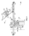
- Fig. 9 illustrates the exemplary embodiment of the clamp actuator system 1000 of Fig. 8 when the actuator 1500 is activated to place the clamp members 1331 in a clamping position.
- the actuation device 1520 is a solenoid.
- a magnetic field is created between the telescoping shaft 1524 and the outer cylinder 1521.
- the shaft 1524 telescopes into the outer cylinder 1521 and pulls the movable bracket 1515 towards the outer cylinder 1521.
- This results in a new tensile force on the cable 1600, which overcomes the spring 1350 force causing the clamp members 1331 to rotate towards a clamping position, as explained in more detail below.
- Fig. 10 is an exploded view illustrating in more detail the trail edge tamper device 1100 of Figs. 8 and 9.
- the trail edge tamper device 1100 includes the trail edge platform 1200 and the trail edge clamp mechanism 1300.
- the trail edge clamp mechanism 1300 includes the substrate support device 1310, a housing 1320 and a clamp assembly 1330 having one or more clamp members 1331.
- the trail edge platform 1200 includes a front surface 1210, an opposing back surface 1230, a groove 1260 and an opening 1270.
- the front surface 1210 includes two protrusions 1220 for aligning and/or connecting the housing 1320 to the trail edge platform.
- the back surface 1230 includes a protrusion 1240 that engages with a guide 1250 to guide the cable 1600.
- the back surface 1230 further includes a groove 1260 that receives and guides the cable 1600 into the housing 1320 (Fig. 12) of the trail edge clamp mechanism 1300 through 'opening 1270.
- the manner in which the cable 1600 is guided through the trail edge platform 1200 is next discussed in greater detail.
- the cable 1600 is guided through the support frame guide members 1402,1403, and enters the trail edge platform 1200 in the direction of arrow 1620.
- the cable 1600 is guided by the guide 1250 into the groove 1260.
- the cable 1600 is guided by the groove 1260 into the opening 1270.
- the cable 1600 is received by the opening 1270 and enters into the trail edge clamp mechanism 1300 in the direction of arrow 1630.
- Fig. 11 illustrates one exemplary embodiment of the trail edge clamp mechanism 1300 of Figs. 8-10.
- the trail edge clamp mechanism 1300 includes the substrate support device 1310, the housing 1320 and the clamp assembly 1330.
- the substrate support device 1310 includes a sheet support surface 1311, preferably substantially horizontal, that is located above a bottom surface of the housing 1320 to support the trail edges of the substrates in the compiled set without the substrates interfering with the movement of the trail edge platform 1200.
- the substrate support device 1310 further includes a tamp plate 1312, preferably substantially vertical, having a front surface that abuts and tamps the trail edges of the substrates in the compiled set.
- the tamp plate 1312 also includes protrusions 1313,1314 on a back surface to connect the substrate support device 1310 to the housing 1320. Further, the tamp plate 1312 includes one or more slots 1315, in a central portion thereof, to receive the clamp members 1331 and allow the clamp members 1331 to be moved between the extended and retracted positions.
- the housing 1320 includes front holes 1321,1322, one or more slots 1325 and side holes 1323,1324.
- the housing 1320 further includes a guide 1326 located at the bottom of the housing 1320 to receive the cable 1600 as the cable 1600 enters from the opening 1270 of the trail edge platform 1200.
- the front holes 1321,1322 are located on a front portion of the housing 1320 to receive the protrusions 1313,1314 of the substrate support device 1310 to connect the substrate support device 1310 to the housing 1320.
- the slots 1325 are also located on the front portion of the housing 1320 and are aligned with the slots 1315 of the substrate support device 1310 to receive the clamp members 1331 and allow the clamp members 1331 to move between the extended and retracted positions.
- the side holes 1323,1324 are located on side portions of the housing 1320 to rotatably support the clamp assembly 1330 so the clamp members 1331 can move between the extended and retracted positions.
- the holes and slots described above may include recesses, slots, openings, and/or the like, as long as they can receive an engaging element. It should be appreciated that, while depicted as having two members, the clamp members 1331 may include one or more than two members. Although depicted as a plurality of slots, the slots 1315,1325 may include one or more slots as long as the slots can receive the clamp members 1331 to allow the clamp members 1331 to move between the extended and retracted positions.
- the clamp assembly 1330 includes the clamp members 1331, a support beam 1332, a guide 1340 and a spring member 1350.
- the support beam 1332 supports the clamp members 1331, the guide 1340 and the spring member 1350. Further, ends of the support beam 1332 engage the side holes 1323,1324 of the housing 1320 to support the support beam 1332 thereon and rotate the clamp members between an extended position and a retracted position for clamping and releasing the trail edge of a compiled set of substrates, respectively.
- the spring member 1350 includes one end portion that engages the housing 1320 and another end portion that engages one of the clamp members 1331, or some other member operatively connected to the clamp members 1331. The spring member 1350 provides a force on the clamp members 1331 that urges the clamp members 1331 'toward the retracted position.
- clamp assembly 1330 while depicted as a combination of several elements, can include one or any desired number of elements. It should also be appreciated that the clamp members 1331, while depicted as a plurality members, can include one or any desired number of members.
- the cable 1600 is guided through the trail edge clamp mechanism 1300 in the direction of arrow 1630.
- the cable 1600 is guided by the guide 1250 (shown in Fig. 10), located at the bottom of the housing 1320, onto the guide 1340 fixed on the support beam 1332 of the trail edge clamp mechanism 1300.
- Fig. 12 illustrates one exemplary embodiment of the guide 1340 of Fig. 12.
- the guide 1340 includes a guide portion 1341, a slot 1342 and a guide cover 1343.
- the cable 1600 is received by the guide portion 1341 of the guide 1340.
- the cable 1600 may be wound around the guide portion 1341 several times to provide better frictional holding of the cable 1600 with respect to the guide 1340.
- the end (not shown) of the cable is held in the slot 1342 via a ball, knot, or the like, attached to the end of the cable.
- the slot 1342 may be slightly smaller than the knot or ball, or may have a reduced portion that creates a tight fit to prevent the cable 1600 from slipping through the slot 1342.
- the guide cover 1343 is affixed to the guide 1340.
- Fig. 13 is a flowchart outlining one exemplary method for clamping and transferring substrates.
- operation of the method begins in step S100, and continues to step S110, where the actuator is deactivated.
- step S120 a trail edge clamp assembly is moved into a retracted position (shown in Fig. 8) so the trail edge assembly can receive a current substrate.
- step S130 the trail edge tamper device is moved to an initial position so that the trail edge assembly can receive a current substrate. Operation then continues to step S140.
- step S140 the current substrate is received by the trail edge clamp mechanism.
- step S150 the current sheet is tamped by moving the trail edge clamp mechanism toward and away from a second position. The second position is located such that the lead edge of the substrate contacts the initial registration surface and the trail edge clamp mechanism contacts the trail edge of the substrate while the substrate remains horizontal.
- step S160 a determination is made whether the current substrate is the last substrate in the set to be compiled. If so, operation continues to step S170. Otherwise, operation returns to step S130.
- step S170 ejection of the compiled set starts.
- the lead edge ejector moves away from the initial registration surface at a distance so that the lead edge platform no longer supports the lead edge of the compiled set.
- the trail edge tamper device 1100 moves along with the moving trail edge platform 1200 at the same distance. Operation then continues to step S180.
- step S180 prior to a lead edge of the compiled set dropping, the actuator is activated to move the trail edge clamp mechanism into a clamping position in order to clamp the trail edge of the compiled set with the clamp assembly. Then, in step S190, the actuator is deactivated. Next, in step S200, the trail edge clamp mechanism is moved into the retracted position and away from the trail edge of the compiled set. Then, in step S210, a determination is made whether another set of substrates is to be compiled. If so, operation returns to step S130. Otherwise, operation 'of the method continues to step S220, where operation of the method ends.
- the "rest” position of the clamp assembly is the position that results when the actuator is deactivated.
- the "rest" position is a clamping position, it will be appreciated that the "deactive actuator” steps could actually be “activate actuator” steps, and vice versa.
Landscapes
- Engineering & Computer Science (AREA)
- Mechanical Engineering (AREA)
- Pile Receivers (AREA)
- Folding Of Thin Sheet-Like Materials, Special Discharging Devices, And Others (AREA)
- Discharge By Other Means (AREA)
- Flexible Shafts (AREA)
- Output Control And Ontrol Of Special Type Engine (AREA)
Abstract
Description
- This invention generally relates to systems and methods for clamping and transferring compiled substrates.
- The compilation or collection of flexible substrates including sheets of paper, plastic, and/or the like, is desirable in various fields of production including individual use, publication, imaging, and/or the like. To maintain proper alignment, or registration, of the substrates is desirable to provide an organized, neatly stacked compilation that can be transferred without unwanted creasing and/or scattering of the substrates.
- Conventional systems and methods for compiling and transferring substrates, such as sheets of paper, are related to an image forming apparatus, such as a copier or printer, or any other device where a compilation of substrates is desired. The substrates can be sorted and/or collated using various types of apparatus, separators, holders, and/or the like. The following U.S. Patents are noted by way of example: U.S. Patent 4,017,066; U.S. Patent 4,589,645; U.S. Patent 4,637,598; U.S. Patent 4,934,683; U.S. Patent 5,026,034; U.S. Patent 5,088,714; U.S. Patent 5,169,135; U.S. Patent 5,915,688; and U.S. patent 5,649,695.
- These conventional systems usually require each compiled set to be transferred from a compilation platform to a stacking tray that holds and/or stacks one or more compiled sets. Each compiled set is usually dropped, pushed out, and/or pulled from the compilation platform in order to transfer the compiled set to the stacking tray.
- In an image forming apparatus, since the lead edge of the compiled set drops first to transfer the compiled set to the holding area, the trail edge of the compiled set is only supported from underneath the bottom substrate of the set. Thus, the trail edges of the substrates in the compiled set still become misaligned in various directions. When the lead edge of the compiled set is not bound with a staple, adhesive, fastener or the like, the potential exists for even greater misalignment.
- This invention provides systems and methods for transferring compiled sets of substrates while reducing the misalignment of the substrates in the compiled sets.
- In embodiments, this invention provides a clamping and transferring system approach that helps reduce the footprint or lateral space requirement to help maximize the efficiency of space used in the finishing devices, i.e. devices which can provide pre-collated sets, compiled sets, bound sets and/or the like, especially in high volume finishing applications that may or may not have multiple discharge paths.
- In embodiments, this invention provides a clamping and transferring system that can handle substrates of various materials, weights and sizes.
- In embodiments, this invention provides a clamping and transferring system that helps reduce the weight of a tamper device and helps increase the efficiency of the alignment of substrates in the compiled set, especially in high speed applications.
- In embodiments, this invention provides a clamping and transferring system approach that provides a force on a cable to clamp substrates in the compiled set.
- In embodiments, this invention provides systems and methods for clamping compiled sets of substrate to reduce the scattering of substrates in the compiled set.
- In embodiments, this invention provides systems and methods for clamping compiled sets of substrate to reduce the scattering of substrates in the compiled set.
- In embodiments, this invention provides system and methods for clamping compiled sets of substrate to ensure that the substrates of each set always remain controlled. That is, by clamping, and therefore positively controlling, the trail edge of the compiled set during the drop and/or transfer from a compile position to the stack, stacking tray, platform or the like, scattering of the substrates in the compiled set is reduced.
- In various exemplary embodiments of the systems and methods according this invention, substrates in a compiled set can be transferred while being clamped.
- In various exemplary embodiments of the systems and methods according this invention, substrates in a compiled set can be transferred to a stacking tray in a controlled manner.
- In various exemplary embodiments of the systems and 'methods according this invention, the clamp actuator system includes an actuator, a cable and a tamper device. The tamper device may include a platform and a clamp mechanism. The clamp mechanism may include a substrate support device and a clamp assembly to clamp a trail edge of a compiled set to reduce scattering of the substrates in the compiled set. The clamp mechanism is preferably lightweight to reduce the weight of a tamper device and help increase the efficiency of the alignment of substrates.
- In various exemplary embodiments of the systems and methods according this invention, the clamp assembly can be retracted and extended. For example, the clamp assembly can be retracted to compile a set of substrates and then extended to transfer the compiled set.
- In various exemplary embodiments of the systems and methods according this invention, the actuator provides a force on the cable to clamp substrates in the compiled set. For example, as the actuator exerts a force on the cable, and preferably the clamp assembly moves from a retracted position to an extended position, the clamp assembly exerts a substantially constant amount of force on the clamped compiled set.
- In various exemplary embodiments of the systems and methods according this invention, the substrates in a compiled set can be transferred to a stacking tray in a controlled manner.
- Various exemplary embodiments of the systems and method according to this invention will be described in detail, with reference to the following figures, wherein:
- Fig. 1 is a schematic diagram of one exemplary embodiment of a substrate compiling system according to this invention;
- Fig. 2 illustrates one exemplary embodiment of a finisher module;
- Fig. 3 illustrates an exemplary compiler/finisher/set stacker system for substrates, showing incoming substrates being compiled and tamped by a clamp actuator system;
- Fig. 4 illustrates the compiler/finisher/set stacker system of Fig. 3, showing a next step in which a set of substrates is compiled, ejected and the clamp actuator system is activated;
- Fig. 5 illustrates the compiler/finisher/set stacker system of Fig. 4, showing a next step in which the compiled set starts to drop while the trail edge of the compiled set is fully clamped by the clamp actuator system;
- Fig. 6 illustrates the compiler/finisher/set stacker system of Fig. 5, showing a next step in which the lead edge of the compiled set has dropped all the way down on top of the previous stacked set on a stacking tray;
- Fig. 7 illustrates the compiler/finisher/set stacker system of Fig. 6, showing a next step in which the clamp actuator system is deactivated to release the trail edge of the compiled set and the trail edge of the compiled set is dropped down on top of a previous stacked set on a stacking tray;
- Fig. 8 illustrates in greater detail one exemplary embodiment of a clamp actuator system according to this invention, where the clamp actuator system is in a retracted position;
- Fig. 9 illustrates in greater detail one exemplary embodiment of the clamp actuator system of Fig. 8, where the clamp actuator system is in an extended position;
- Fig. 10 is an exploded view showing in greater detail one exemplary embodiment of a trail edge tamper device of the of the clamp actuator system of Figs. 8 and 9;
- Fig. 11 is a perspective view showing in greater detail one exemplary embodiment of a trail edge clamp mechanism of the clamp actuator system of Figs. 8 and 9;
- Fig. 12 is a perspective view showing in greater detail one exemplary embodiment of a guide of the trail edge clamp mechanism of Fig. 12; and
- Fig. 13 is a flowchart outlining one exemplary embodiment of a method for clamping and transferring a compiled set of substrates using the clamp actuator system.
-
- Various exemplary embodiments of the systems and methods according to this invention enable the clamping and transfer of flexible substrates in an image-forming system, substrate compilation system, or the like, to be advanced through the use of a clamp actuator system. Mechanisms and techniques used in the clamp actuator system according to this invention provide a combination of tamping, clamping and transporting.
- Fig. 1 is a block diagram of one exemplary embodiment of a substrate-compiling
system 100 in which a substrate may need to be registered and transported. As shown in Fig. 1, the substrate-compiling system 100 includes asubstrate feed module 200, asubstrate processing module 300 and afinisher module 400. - It should be appreciated that the
substrate feed module 200, thesubstrate processing module 300 and thefinisher module 400, while depicted as components of the substrate-compiling system 100 in Fig. 1, are not necessarily components of a single system. The functions and/or operations of any one or more of these elements may be carried out by separate and distinct devices, structures, and/or systems. Further, it should be appreciated that additional devices, structures and/or systems may be included in the substrate-compilingsystem 100, such as, for example, a substrate preparation module. - Fig. 2 illustrates one exemplary embodiment of the
finisher module 400. As shown in Fig. 2, the finisher module, 400 includes asubstrate receiving inlet 402, amain transport path 404,transport nip rollers 406, abypass path 408, atop bypass tray 410,diverter gates 412, a pair of retractable compiling shutters 414 (only one shutter is shown in this view since both shutters are located in the same horizontal plane), amanipulation device 416, alead edge ejector 417, alead edge system 418, aclamp actuator system 1000, anoutput unit 430,drive rollers 431, anoutput tray 432 and astacking tray 440 for receiving compiled sets of substrates. A number of pairs oftransport nip rollers 406 move the substrates along themain transport path 404 and/or thebypass path 408. - The
manipulation device 416 can be any device capable of manipulating a substrate or a set of substrates, including, but not limited to, stapling, binding, punching, stitching, perforating and/or the like. It should be appreciated that themanipulation device 416 may be a separate component in thefinisher module 400 and that the location and/or capability of themanipulation device 416 is a design choice and will be obvious to those skilled in the art. - It should further be appreciated that the
manipulation device 416, while depicted as a component of thefinisher module 400 in Fig. 2, is not necessarily a component of a single system. The functions and/or operations of themanipulation device 416 may be carried out by any number of separate and distinct devices, structures, and/or systems. - In operation, substrates are received from the
substrate processing module 300 through thesubstrate receiving inlet 402. Substrates are transported along themain transport path 404 by the one or more pairs oftransport nip rollers 406. Substrates that are not to be compiled into a set can be diverted to thetop bypass tray 410 along thebypass path 408. Further, substrates that are not compiled into a set can be diverted to theoutput tray 432 along themain transport path 404 via aguide baffle 413 and thedrive rollers 431 of theoutput unit 430. Otherwise, substrates are transported by thetransport nip rollers 406 along themain transport path 404 and are diverted to the retractable compilingshutters 414 by one of thediverter gates 412 that divert the substrates sequentially onto upper surfaces of the retractable compilingshutters 414. The'appropriate one of thediverter gates 412 used to divert the substrates can be determined based on the dimensions of the substrates. - It should be appreciated that the compiled sets stack
tray 440 can be any platform, surface or the like capable of holding a set of compiled substrates after the compiled set is clamped and transferred. - Figs. 3-7 illustrate various exemplary stages of operation of the
finisher module 400. - As shown in Fig. 3, a
substrate 10 is transported by the transport niprollers 406 and sequentially diverted by one of thediverter gates 412 to form a compiled set of substrates. After thesubstrate 10 is diverted by one of thediverter gates 412, the substrate is temporarily supported by theretractable compiling shutters 414, a trailedge tamper device 1100 via asubstrate support device 1310, and alead edge guide 418 via alead edge platform 419. Further, after thesubstrate 10 of the compiled set is supported by the above process and/or placed on top of another substrate in the set, thesubstrate 10 is aligned by the trailedge tamper device 1100 and side tampers (not shown). To align or tamp thesubstrate 10, the trailedge tamper device 1100 starts at an initial position in Fig. 3. Then, the trailedge tamper device 1100 moves along with the movingtrail edge platform 1200 in the direction ofarrow 1333 to push the substrate flush against aninitial registration surface 415. Next, the movingtrail edge platform 1200 returns to the initial position. The process described above is performed for eachsubstrate 10 of the compiled set until the entire set of substrates is neatly stacked and compiled into an aligned compiled set. - Each compiled set of substrates may then be stapled, bound, punched, stitched, perforated and/or the like by the
manipulation device 416, located in the area of thelead edge platform 419. After a set has been compiled and optionally manipulated, the set ejection process begins. - Figs. 4 and 5 illustrate the ejection of the compiled set of substrates. As shown in Fig. 4, the
lead edge ejector 417 pushes a lead edge of the compiled set in the direction ofarrow 413 away from theinitial registration surface 415 until thelead edge platform 419 no longer supports the lead edge of the compiled set. As the lead edge of the compiled set is pushed by thelead edge ejector 417, the trailedge tamper device 1100 moves along with the movingtrail edge platform 1200 in the direction ofarrow 1334, theclamp members 1331 pivots in the direction ofarrow 1335, and theretractable compiling shutters 414 move away from each other. - Next, as shown in Fig. 5, the lead edge of the compiled set is dropped to compiled sets stack
tray 440 below. After the lead edge of the compiled set clears thelead edge platform 419, theretractable compiling shutters 414 are moved apart far enough to positions that remove edge support of the compiled set and the trailedge tamper device 1100 stops moving in the direction ofarrow 1334. During the time when the lead edge of the compiled set is being cleared from the lead edge platform or edge support of the compiled set is being removed, theclamp members 1331 are fully extended in the direction of thearrow 1335 to clamp the compiled set to thesubstrate support device 1310 to keep the trail edge of the compiled set from slipping off thesubstrate support device 1310 as the lead edge of the compiled set drops in the direction ofarrow 421 to the compiled sets stacktray 440 below. However, theclamp members 1331 are in a fully extended position before the compilingshutters 414 are moved to the positions that completely remove edge support of the compiled set. - Fig. 6 illustrates the lead edge of the compiled set clamped down by the
lead edge system 418 onto the top of the preceding stacked compiled set to prevent or reduce undesired movement of the current compiled set after the trail edge of the compiled set is dropped from the trailedge tamper device 1100 and lands on thelead edge system 418. - Fig. 7 illustrates the trail edge of the compiled set 'being dropped to compiled sets stack
tray 440 below. After the lead edge of the compiled set is clamped by thelead edge system 418, the trailedge tamper device 1100 starts moving along with the movingtrail edge platform 1200 in the direction ofarrow 1336. During the time when the trailedge tamper device 1100 starts moving along with the movingtrail edge platform 1200, theclamp members 1331 concurrently rotate in the direction of thearrow 1337 to release the trail edge of the compiled set so the compiled set drops in the direction ofarrow 1338 to the compiled sets stacktray 440 below. Finally, the trailedge tamper device 1100 returns to the initial position and the operation discussed above with respect to Figs. 3-7 then repeats to compile the next set of substrates for another compiled set. - It should be appreciated that the stacking tray can be any platform, surface, or the like capable of holding a set of compiled substrates after the compiled set is clamped and transferred. It should be also be appreciated that the actuator can be any device such as a motor assembly, manual lever or the like, capable of applying a force on the cable to allow the clamp mechanism to clamp a set of compiled substrates during the transfer of the compiled set to a stacking tray, platform, surface or the like.
- The operation of the substrate-compiling
system 100, including thefinisher module 400 discussed above, operates under the control of a controller (not shown) in accordance with a program stored in a memory (not shown) and/or in response to feedback from any desired or necessary sensors (not shown) , as will be appreciated by those skilled in the art. - The memory can be implemented using any appropriate combination of alterable, volatile or non-volatile memory or non-alterable, or fixed, memory. The alterable memory, whether volatile or non-volatile, can be implemented by using any one or more of static or dynamic RAM, a floppy disk and disk drive, a writeable or rewriteable optical disk and disk drive, a hard drive, flash memory or the like. Similarly, the non-alterable or fixed memory can be implemented using any one or more of ROM, PROM, EPROM, EEPROM, and gaps in optical ROM disk, such as a CD ROM or DVD ROM disk and disk drive, or the like.
- Fig. 8 illustrates in greater detail one exemplary embodiment of the
clamp actuator system 1000. As shown in Fig. 8, theclamp actuator system 1000 includes a trailedge tamper device 1100, support frame guide members 1400-1403, anactuator 1500 and acable 1600. The trailedge tamper device 1100 includes thetrail edge platform 1200 and a trailedge clamp mechanism 1300. Further, the trailedge clamp mechanism 1300 includes thesubstrate support device 1310 and ahousing 1320 that supports theclamp members 1331. In Fig. 8, theactuator 1500 is in a deactivated state with theclamp members 1331 in a retracted position. - As shown in Fig. 8, the
actuator 1500 includes aguide bracket 1510 and anactuation device 1520. Theguide bracket 1510 is a two-piece bracket including a fixedbracket 1511 and amovable bracket 1515. The fixedbracket 1511 is fixed to a support frame (not shown) of a compiling device and includesguide members movable bracket 1515 includes aguide member 1516 and a pair of engaging through-holes 1517 that engage the pair ofparallel engagement posts 1514 of the fixedbracket 1511. Theguide members guide members 1400,1410 fixed on the support frame, are guide members that guide thecable 1600. - As shown in Fig. 8, the
actuation device 1520 includes anouter cylinder 1521 and atelescoping shaft 1524. Theouter cylinder 1521 is fixed to the support frame by asupport bracket 1522. Additionally, theouter cylinder 1521 has a fixedcollar 1523 that receives one end of thetelescoping shaft 1524. The other end of the telescoping shaft includes a fixedcollar 1525 and is connected to themovable bracket 1515 to manipulate thecable 1600. - The manner in which the
cable 1600 is guided throughout theclamp actuator system 1000 will be discussed in greater detail with respect to Figs. 8-13. However, it should be appreciated that the guiding of thecable 1600 throughout theclamp actuator system 1000 is not limited to the following described sequence, e.g., the cable could be guided throughout theclamp actuator system 1000 in an opposite direction as long as the cable starts and ends at the trailedge clamp mechanism 1300. - One
end 1610 of thecable 1600 is fixed to thetrail edge platform 1200. Thecable 1600 is guided through the supportframe guide members guide member 1513 of the fixedbracket 1511, beneath theguide member 1516 of themovable bracket 1515, above theguide member 1512 of the fixedbracket 1511, through the supportframe guide members edge tamper device 1100. The other end of thecable 1600 is fixed to the trailedge clamp mechanism 1300, as will be explained in greater detail hereafter. Since thecable 1600 is guided throughout theclamp actuator system 1000, the activation of theactuation device 1520 manipulates thecable 1600, which in turn manipulates the trailedge tamper device 1100 to operate theclamp members 1331. - The
cable 1600 is preferably a light-gauge braided or twisted steel cable, but may also be or include a single wire, rope, and/or the like, and/or may be of any desired material or combination of materials, as long as thecable 1600 is flexible and can support tensile loads. Further, it should also be appreciated that the guides can include pulleys, grooves, and/or any surface or device capable of guiding the cable. It should be also be appreciated that the actuator can include any device such as a solenoid assembly, hydraulic cylinder, threadedly extensible device, or the like, capable of applying a force on the cable to allow the clamp mechanism to clamp a set of compiled substrates during the transfer of the compiled set to a stacking tray, platform, surface or the like. Further, it should be appreciated that the actuator, while depicted as a combination of several elements, can be any desired or necessary number of elements. - Fig. 9 illustrates the exemplary embodiment of the
clamp actuator system 1000 of Fig. 8 when theactuator 1500 is activated to place theclamp members 1331 in a clamping position. In this example, it is assumed that theactuation device 1520 is a solenoid. When theactuation device 1520 is activated, a magnetic field is created between thetelescoping shaft 1524 and theouter cylinder 1521. As a result, theshaft 1524 telescopes into theouter cylinder 1521 and pulls themovable bracket 1515 towards theouter cylinder 1521. This in turn results in a new tensile force on thecable 1600, which overcomes thespring 1350 force causing theclamp members 1331 to rotate towards a clamping position, as explained in more detail below. - Fig. 10 is an exploded view illustrating in more detail the trail
edge tamper device 1100 of Figs. 8 and 9. As shown in Fig. 10, the trailedge tamper device 1100 includes thetrail edge platform 1200 and the trailedge clamp mechanism 1300. The trailedge clamp mechanism 1300 includes thesubstrate support device 1310, ahousing 1320 and aclamp assembly 1330 having one ormore clamp members 1331. Several components of the trailedge tamper device 1100 are discussed in greater detail herein after. - As shown in Fig. 10, the
trail edge platform 1200 includes afront surface 1210, an opposingback surface 1230, agroove 1260 and anopening 1270. Thefront surface 1210 includes twoprotrusions 1220 for aligning and/or connecting thehousing 1320 to the trail edge platform. Theback surface 1230 includes aprotrusion 1240 that engages with aguide 1250 to guide thecable 1600. Theback surface 1230 further includes agroove 1260 that receives and guides thecable 1600 into the housing 1320 (Fig. 12) of the trailedge clamp mechanism 1300 through 'opening 1270. - The manner in which the
cable 1600 is guided through thetrail edge platform 1200 is next discussed in greater detail. Thecable 1600 is guided through the supportframe guide members trail edge platform 1200 in the direction ofarrow 1620. Thecable 1600 is guided by theguide 1250 into thegroove 1260. Thecable 1600 is guided by thegroove 1260 into theopening 1270. Thecable 1600 is received by theopening 1270 and enters into the trailedge clamp mechanism 1300 in the direction ofarrow 1630. - Fig. 11 illustrates one exemplary embodiment of the trail
edge clamp mechanism 1300 of Figs. 8-10. As shown in Fig. 11, the trailedge clamp mechanism 1300 includes thesubstrate support device 1310, thehousing 1320 and theclamp assembly 1330. Thesubstrate support device 1310 includes asheet support surface 1311, preferably substantially horizontal, that is located above a bottom surface of thehousing 1320 to support the trail edges of the substrates in the compiled set without the substrates interfering with the movement of thetrail edge platform 1200. Thesubstrate support device 1310 further includes a tampplate 1312, preferably substantially vertical, having a front surface that abuts and tamps the trail edges of the substrates in the compiled set. The tampplate 1312 also includesprotrusions substrate support device 1310 to thehousing 1320. Further, the tampplate 1312 includes one ormore slots 1315, in a central portion thereof, to receive theclamp members 1331 and allow theclamp members 1331 to be moved between the extended and retracted positions. - As shown in Fig. 11, the
housing 1320 includesfront holes 1321,1322, one ormore slots 1325 andside holes housing 1320 further includes aguide 1326 located at the bottom of thehousing 1320 to receive thecable 1600 as thecable 1600 enters from theopening 1270 of thetrail edge platform 1200. The front holes 1321,1322 are located on a front portion of thehousing 1320 to receive theprotrusions substrate support device 1310 to connect thesubstrate support device 1310 to thehousing 1320. Further, theslots 1325 are also located on the front portion of thehousing 1320 and are aligned with theslots 1315 of thesubstrate support device 1310 to receive theclamp members 1331 and allow theclamp members 1331 to move between the extended and retracted positions. The side holes 1323,1324 are located on side portions of thehousing 1320 to rotatably support theclamp assembly 1330 so theclamp members 1331 can move between the extended and retracted positions. - It should be appreciated that the holes and slots described above may include recesses, slots, openings, and/or the like, as long as they can receive an engaging element. It should be appreciated that, while depicted as having two members, the
clamp members 1331 may include one or more than two members. Although depicted as a plurality of slots, theslots clamp members 1331 to allow theclamp members 1331 to move between the extended and retracted positions. - As shown in Fig. 11, the
clamp assembly 1330 includes theclamp members 1331, asupport beam 1332, aguide 1340 and aspring member 1350. Thesupport beam 1332 supports theclamp members 1331, theguide 1340 and thespring member 1350. Further, ends of thesupport beam 1332 engage the side holes 1323,1324 of thehousing 1320 to support thesupport beam 1332 thereon and rotate the clamp members between an extended position and a retracted position for clamping and releasing the trail edge of a compiled set of substrates, respectively. Thespring member 1350 includes one end portion that engages thehousing 1320 and another end portion that engages one of theclamp members 1331, or some other member operatively connected to theclamp members 1331. Thespring member 1350 provides a force on theclamp members 1331 that urges the clamp members 1331 'toward the retracted position. - It should be appreciated that the
clamp assembly 1330, while depicted as a combination of several elements, can include one or any desired number of elements. It should also be appreciated that theclamp members 1331, while depicted as a plurality members, can include one or any desired number of members. - The manner in which the
cable 1600 is guided through the trailedge clamp mechanism 1300 is next discussed in greater detail. After thecable 1600 is received through theopening 1270 of thetrail edge platform 1200, thecable 1600 enters the trailedge clamp mechanism 1300 in the direction ofarrow 1630. Then, thecable 1600 is guided by the guide 1250 (shown in Fig. 10), located at the bottom of thehousing 1320, onto theguide 1340 fixed on thesupport beam 1332 of the trailedge clamp mechanism 1300. - Fig. 12 illustrates one exemplary embodiment of the
guide 1340 of Fig. 12. As shown in Fig. 12, theguide 1340 includes aguide portion 1341, aslot 1342 and aguide cover 1343. Thecable 1600 is received by theguide portion 1341 of theguide 1340. Thecable 1600 may be wound around theguide portion 1341 several times to provide better frictional holding of thecable 1600 with respect to theguide 1340. The end (not shown) of the cable is held in theslot 1342 via a ball, knot, or the like, attached to the end of the cable. It should be appreciated that theslot 1342 may be slightly smaller than the knot or ball, or may have a reduced portion that creates a tight fit to prevent thecable 1600 from slipping through theslot 1342. In order to prevent thewound cable 1600 from slipping off of theguide 1340, theguide cover 1343 is affixed to theguide 1340. - Fig. 13 is a flowchart outlining one exemplary method for clamping and transferring substrates. As show in Fig. 13, operation of the method begins in step S100, and continues to step S110, where the actuator is deactivated. Then, in step S120, a trail edge clamp assembly is moved into a retracted position (shown in Fig. 8) so the trail edge assembly can receive a current substrate. Next, in step S130, the trail edge tamper device is moved to an initial position so that the trail edge assembly can receive a current substrate. Operation then continues to step S140.
- In step S140, the current substrate is received by the trail edge clamp mechanism. Then, in step S150, the current sheet is tamped by moving the trail edge clamp mechanism toward and away from a second position. The second position is located such that the lead edge of the substrate contacts the initial registration surface and the trail edge clamp mechanism contacts the trail edge of the substrate while the substrate remains horizontal. Then, in step S160, a determination is made whether the current substrate is the last substrate in the set to be compiled. If so, operation continues to step S170. Otherwise, operation returns to step S130.
- In step S170, ejection of the compiled set starts. To eject the compiled set, the lead edge ejector moves away from the initial registration surface at a distance so that the lead edge platform no longer supports the lead edge of the compiled set. As the lead edge of the compiled set is pushed by the
lead edge ejector 417, the trailedge tamper device 1100 moves along with the movingtrail edge platform 1200 at the same distance. Operation then continues to step S180. - In step S180, prior to a lead edge of the compiled set dropping, the actuator is activated to move the trail edge clamp mechanism into a clamping position in order to clamp the trail edge of the compiled set with the clamp assembly. Then, in step S190, the actuator is deactivated. Next, in step S200, the trail edge clamp mechanism is moved into the retracted position and away from the trail edge of the compiled set. Then, in step S210, a determination is made whether another set of substrates is to be compiled. If so, operation returns to step S130. Otherwise, operation 'of the method continues to step S220, where operation of the method ends.
- In the foregoing description, it is assumed that the "rest" position of the clamp assembly is the position that results when the actuator is deactivated. However, if the "rest" position is a clamping position, it will be appreciated that the "deactive actuator" steps could actually be "activate actuator" steps, and vice versa.
Claims (10)
- A,substrate compiling system, comprising:wherein the tamper device (1100) tamps a trailing edge of a compiled set of substrates (10), the actuator (1500) manipulates the cable (1600) to cause the tamper device (1100) to clamp the trailing edge of the compiled set and to release the trailing edge of the compiled set.an actuator (1500);a cable (1600) guided through the actuator (1500); and,a tamper device (1100) connected to the cable (1600),
- A substrate compiling system according to claim 1, wherein the tamper device (1100) continues to clamp the compiled set until a leading edge of the compiled set, opposing the trailing edge of the compiled set, engages a lower platform (440).
- A substrate compiling system according to claim 1 or 2, wherein the actuator includes:an actuation device (1520);a guide bracket (1522) connected to the actuation device (1520) ; and,a guide (1511) connected to the guide bracket (1522) to guide the cable (1600) to activate the tamper device (1100).
- A substrate compiling system according to any one of the preceding claims, wherein the tamper device (1100) includes:a platform (1200) that guides the cable (1600); and,a clamp mechanism (1300) connected to and supported by the platform (1200), wherein the platform (1200) is moved to position the clamp mechanism (1300) to tamp and align the trailing edge of the compiled set.
- A substrate compiling system according to claim 4, wherein the clamp mechanism (1300) includes:a substrate support device (1311);a housing (1320) that supports the substrate support device (1311); and,a clamp assembly (1331) connected to and supported by the support member.
- A substrate compiling system of claim 5, wherein a movement of the platform (1200) is not affected by a manipulation of the cable (1600) by the actuator (1520).
- A substrate compiling system of claim 5 or 6, wherein the clamp assembly (1331) rotates with respect to the housing (1320) into an extended position, to clamp the 'trailing edge of the compiled set, and a retracted position, to release the trailing edge of the compiled set.
- A substrate compiling system, comprising:wherein the actuator moves the tamper device into an extended position to clamp the trail edge of the compiled set, the actuator moves the tamper device into a retracted position to release the trail edge of the compiled set.an actuator; anda tamper device connected the actuator,
- A method for clamping and transferring substrates of a compiled set, comprising:moving the clamp assembly from a retracted position to an extended position to clamp an edge of the compiled set;moving the clamp assembly to drop the edge of the compiled set; andmoving the clamp assembly from the extended position to the retracted position to release the edge of the compiled set.
- A method for clamping and transferring substrates of a compiled set, comprising:moving a clamp assembly from a retracted position to an extended position to clamp an edge of the compiled set; andmoving the clamp assembly from the extended position to the retracted position to release the edge of the compiled set.
Applications Claiming Priority (2)
| Application Number | Priority Date | Filing Date | Title |
|---|---|---|---|
| US740491 | 2003-12-22 | ||
| US10/740,491 US7021617B2 (en) | 2003-12-22 | 2003-12-22 | Clamp actuator system and method of use |
Publications (2)
| Publication Number | Publication Date |
|---|---|
| EP1550627A1 true EP1550627A1 (en) | 2005-07-06 |
| EP1550627B1 EP1550627B1 (en) | 2008-05-21 |
Family
ID=34574727
Family Applications (1)
| Application Number | Title | Priority Date | Filing Date |
|---|---|---|---|
| EP04257671A Expired - Lifetime EP1550627B1 (en) | 2003-12-22 | 2004-12-09 | Clamp actuator system and method |
Country Status (5)
| Country | Link |
|---|---|
| US (1) | US7021617B2 (en) |
| EP (1) | EP1550627B1 (en) |
| JP (1) | JP4898116B2 (en) |
| BR (1) | BRPI0405754A (en) |
| DE (1) | DE602004013913D1 (en) |
Cited By (2)
| Publication number | Priority date | Publication date | Assignee | Title |
|---|---|---|---|---|
| CN106185429A (en) * | 2015-05-25 | 2016-12-07 | 株式会社东芝 | Sheet material processing apparatus |
| CN106241472A (en) * | 2015-06-08 | 2016-12-21 | 株式会社东芝 | Sheet material processing apparatus |
Families Citing this family (4)
| Publication number | Priority date | Publication date | Assignee | Title |
|---|---|---|---|---|
| US8020857B2 (en) * | 2005-09-15 | 2011-09-20 | Toshiba Tec Kabushiki Kaisha | Paper sheet processing apparatus, and paper sheet processing method |
| US7900904B2 (en) * | 2007-04-30 | 2011-03-08 | Xerox Corporation | Modular finishing assembly with function separation |
| KR101308487B1 (en) * | 2011-09-01 | 2013-09-25 | 주식회사신도리코 | Apparatus for clamping paper of office machine |
| US11479435B2 (en) * | 2020-01-30 | 2022-10-25 | Riso Kagaku Corporation | Medium ejection apparatus |
Citations (4)
| Publication number | Priority date | Publication date | Assignee | Title |
|---|---|---|---|---|
| GB2157272A (en) * | 1984-04-11 | 1985-10-23 | Jagenberg Ag | Interrupting flow of sheets to a stack |
| US4589645A (en) * | 1985-10-03 | 1986-05-20 | Xerox Corporation | Document set separator and stack height sensor |
| US5484256A (en) * | 1994-01-22 | 1996-01-16 | Jagenberg Papiertechnik Gmbh | Clamping device, especially for clamping a stack during stack changes in a stacking apparatus |
| US5649695A (en) * | 1996-02-01 | 1997-07-22 | Gradco (Japan) Ltd. | Continuous sheet stacker and finisher |
Family Cites Families (28)
| Publication number | Priority date | Publication date | Assignee | Title |
|---|---|---|---|---|
| US3556503A (en) | 1968-10-14 | 1971-01-19 | Vanguard Corp | Side bearing for railroad cars |
| US3670661A (en) | 1970-03-02 | 1972-06-20 | Mcmullen Ass John J | Resilient roll controlling railway car side bearings |
| US3735711A (en) | 1971-07-16 | 1973-05-29 | Evans Prod Co | Elastomeric railway car side bearing |
| US3910655A (en) | 1974-04-01 | 1975-10-07 | Midland Ross Corp | Constant contact side bearing |
| US3932005A (en) | 1974-05-10 | 1976-01-13 | Uniroyal Inc. | Elastomeric railway car with side bearing |
| US3957318A (en) | 1974-05-16 | 1976-05-18 | A. Stuck, Company | Elastomeric railway truck side bearing |
| US4134672A (en) * | 1976-03-30 | 1979-01-16 | Eastman Kodak Company | Copier finisher for an electrographic reproducing device |
| US4017066A (en) | 1976-06-04 | 1977-04-12 | Xerox Corporation | Set separator |
| DE3023533C2 (en) * | 1980-06-24 | 1982-11-25 | Bielomatik Leuze Gmbh + Co, 7442 Neuffen | Device for depositing sheets in a pile |
| US4355583A (en) | 1980-11-12 | 1982-10-26 | The Budd Company | Side bearing for a railway car |
| NL190130C (en) * | 1982-04-20 | 1993-11-01 | Adrianus Maria Josephus Bruin | DEVICE FOR PROTECTION AGAINST PRESSURE IN A FLOWING MEDIUM SUPPLY LINE. |
| DE3220095A1 (en) * | 1982-05-28 | 1983-12-01 | Bielomatik Leuze Gmbh + Co, 7442 Neuffen | METHOD AND DEVICE FOR REMOVING STACKS OF SHEETS |
| NL8402365A (en) | 1984-07-27 | 1986-02-17 | Oce Nederland Bv | HOLDER FOR A STACK OF SHEETS. |
| US4567833A (en) | 1984-09-20 | 1986-02-04 | Holland Company | Composite constant contact side bearing for railroad cars |
| JPS63288850A (en) | 1987-05-18 | 1988-11-25 | Canon Inc | Automatic document feeder |
| US4793720A (en) | 1988-01-21 | 1988-12-27 | American Standard Inc. | Railway car resilient side bearing |
| JP2781912B2 (en) * | 1988-09-08 | 1998-07-30 | エヌティエヌ株式会社 | Linear motor |
| US4998997A (en) | 1989-02-15 | 1991-03-12 | Miner Enterprises, Inc. | Side bearing unit for railroad car |
| JP2838534B2 (en) | 1989-04-06 | 1998-12-16 | コニカ株式会社 | Document feeder |
| US5026034A (en) | 1989-06-19 | 1991-06-25 | Eastman Kodak Company | Document output apparatus having anti-dishevelment device |
| US5088714A (en) | 1989-09-21 | 1992-02-18 | Sharp Kabushiki Kaisha | Recirculating sheet feeder |
| US5386783A (en) | 1990-02-01 | 1995-02-07 | Hansen Inc. | Railway truck side bearing |
| JP3696893B2 (en) * | 1993-04-07 | 2005-09-21 | キヤノン株式会社 | Sheet post-processing apparatus having sheet bundle transfer means |
| US5601031A (en) | 1994-06-14 | 1997-02-11 | Miner Enterprises, Inc. | Constant contact side bearing |
| DE19541792B4 (en) | 1995-11-09 | 2004-09-30 | Heidelberger Druckmaschinen Ag | Device for auxiliary stack formation when changing non-stop stacks in the delivery of a printing press |
| US6357736B1 (en) * | 1997-05-26 | 2002-03-19 | Nisca Corporation | Sheet post-handling device |
| US6092470A (en) | 1998-12-03 | 2000-07-25 | Miner Enterprises, Inc. | Railroad car side bearing with thermal insulator |
| US6819906B1 (en) * | 2003-08-29 | 2004-11-16 | Xerox Corporation | Printer output sets compiler to stacker system |
-
2003
- 2003-12-22 US US10/740,491 patent/US7021617B2/en not_active Expired - Fee Related
-
2004
- 2004-12-09 DE DE602004013913T patent/DE602004013913D1/en not_active Expired - Lifetime
- 2004-12-09 EP EP04257671A patent/EP1550627B1/en not_active Expired - Lifetime
- 2004-12-17 JP JP2004366882A patent/JP4898116B2/en not_active Expired - Fee Related
- 2004-12-21 BR BR0405754-6A patent/BRPI0405754A/en not_active IP Right Cessation
Patent Citations (4)
| Publication number | Priority date | Publication date | Assignee | Title |
|---|---|---|---|---|
| GB2157272A (en) * | 1984-04-11 | 1985-10-23 | Jagenberg Ag | Interrupting flow of sheets to a stack |
| US4589645A (en) * | 1985-10-03 | 1986-05-20 | Xerox Corporation | Document set separator and stack height sensor |
| US5484256A (en) * | 1994-01-22 | 1996-01-16 | Jagenberg Papiertechnik Gmbh | Clamping device, especially for clamping a stack during stack changes in a stacking apparatus |
| US5649695A (en) * | 1996-02-01 | 1997-07-22 | Gradco (Japan) Ltd. | Continuous sheet stacker and finisher |
Cited By (3)
| Publication number | Priority date | Publication date | Assignee | Title |
|---|---|---|---|---|
| CN106185429A (en) * | 2015-05-25 | 2016-12-07 | 株式会社东芝 | Sheet material processing apparatus |
| CN106241472A (en) * | 2015-06-08 | 2016-12-21 | 株式会社东芝 | Sheet material processing apparatus |
| CN106241472B (en) * | 2015-06-08 | 2018-02-06 | 株式会社东芝 | Sheet material processing apparatus |
Also Published As
| Publication number | Publication date |
|---|---|
| EP1550627B1 (en) | 2008-05-21 |
| BRPI0405754A (en) | 2005-08-30 |
| US20050206065A1 (en) | 2005-09-22 |
| US7021617B2 (en) | 2006-04-04 |
| JP2005179062A (en) | 2005-07-07 |
| JP4898116B2 (en) | 2012-03-14 |
| DE602004013913D1 (en) | 2008-07-03 |
Similar Documents
| Publication | Publication Date | Title |
|---|---|---|
| CA2477228C (en) | Printer output sets compiler to stacker system | |
| JP3748710B2 (en) | Sheet processing device | |
| US6450492B1 (en) | Method and apparatus for set binding, stapling and stacking | |
| EP0498546B1 (en) | Finishing apparatus | |
| US20080265484A1 (en) | Sheet post processing apparatus and image forming system | |
| EP1550627B1 (en) | Clamp actuator system and method | |
| JP4184971B2 (en) | Copier paper handling equipment | |
| CA2185951A1 (en) | Continuous sheet stacker and finisher | |
| US20100195119A1 (en) | Paper sheet stacking device, and bookbinding device | |
| US7175174B2 (en) | Waiting tray for sheet processing tray | |
| US20100044945A1 (en) | Paper sheet handling device | |
| JP4518925B2 (en) | Paper post-processing device | |
| US20100295231A1 (en) | Paper sheet handling device | |
| EP0517903B1 (en) | Modular finisher for a reproduction apparatus | |
| JP3655407B2 (en) | Paper post-processing device | |
| US7159860B2 (en) | Strike down mechanism for sheet processing device | |
| JP4297361B2 (en) | Sheet post-processing device | |
| JP4063659B2 (en) | Paper transport device, paper processing device, and image forming system | |
| US20060066024A1 (en) | Sheet post-process apparatus | |
| JP4407370B2 (en) | Image forming system | |
| JP2002316768A (en) | Sheet post-processing equipment | |
| JP4104288B2 (en) | Paper processing device | |
| JP2004123357A (en) | Post-treatment device | |
| US20060066026A1 (en) | Sheet post-process apparatus | |
| JP4988503B2 (en) | Sheet post-processing apparatus and image forming apparatus |
Legal Events
| Date | Code | Title | Description |
|---|---|---|---|
| PUAI | Public reference made under article 153(3) epc to a published international application that has entered the european phase |
Free format text: ORIGINAL CODE: 0009012 |
|
| AK | Designated contracting states |
Kind code of ref document: A1 Designated state(s): AT BE BG CH CY CZ DE DK EE ES FI FR GB GR HU IE IS IT LI LT LU MC NL PL PT RO SE SI SK TR |
|
| AX | Request for extension of the european patent |
Extension state: AL BA HR LV MK YU |
|
| 17P | Request for examination filed |
Effective date: 20060109 |
|
| AKX | Designation fees paid |
Designated state(s): DE FR GB |
|
| 17Q | First examination report despatched |
Effective date: 20070529 |
|
| GRAP | Despatch of communication of intention to grant a patent |
Free format text: ORIGINAL CODE: EPIDOSNIGR1 |
|
| GRAC | Information related to communication of intention to grant a patent modified |
Free format text: ORIGINAL CODE: EPIDOSCIGR1 |
|
| RTI1 | Title (correction) |
Free format text: CLAMP ACTUATOR SYSTEM AND METHOD |
|
| GRAS | Grant fee paid |
Free format text: ORIGINAL CODE: EPIDOSNIGR3 |
|
| GRAA | (expected) grant |
Free format text: ORIGINAL CODE: 0009210 |
|
| AK | Designated contracting states |
Kind code of ref document: B1 Designated state(s): DE FR GB |
|
| REG | Reference to a national code |
Ref country code: GB Ref legal event code: FG4D |
|
| REF | Corresponds to: |
Ref document number: 602004013913 Country of ref document: DE Date of ref document: 20080703 Kind code of ref document: P |
|
| PLBE | No opposition filed within time limit |
Free format text: ORIGINAL CODE: 0009261 |
|
| STAA | Information on the status of an ep patent application or granted ep patent |
Free format text: STATUS: NO OPPOSITION FILED WITHIN TIME LIMIT |
|
| 26N | No opposition filed |
Effective date: 20090224 |
|
| REG | Reference to a national code |
Ref country code: FR Ref legal event code: PLFP Year of fee payment: 12 |
|
| REG | Reference to a national code |
Ref country code: FR Ref legal event code: PLFP Year of fee payment: 13 |
|
| PGFP | Annual fee paid to national office [announced via postgrant information from national office to epo] |
Ref country code: GB Payment date: 20161128 Year of fee payment: 13 Ref country code: FR Payment date: 20161121 Year of fee payment: 13 Ref country code: DE Payment date: 20161121 Year of fee payment: 13 |
|
| REG | Reference to a national code |
Ref country code: DE Ref legal event code: R119 Ref document number: 602004013913 Country of ref document: DE |
|
| GBPC | Gb: european patent ceased through non-payment of renewal fee |
Effective date: 20171209 |
|
| REG | Reference to a national code |
Ref country code: FR Ref legal event code: ST Effective date: 20180831 |
|
| PG25 | Lapsed in a contracting state [announced via postgrant information from national office to epo] |
Ref country code: FR Free format text: LAPSE BECAUSE OF NON-PAYMENT OF DUE FEES Effective date: 20180102 Ref country code: DE Free format text: LAPSE BECAUSE OF NON-PAYMENT OF DUE FEES Effective date: 20180703 |
|
| PG25 | Lapsed in a contracting state [announced via postgrant information from national office to epo] |
Ref country code: GB Free format text: LAPSE BECAUSE OF NON-PAYMENT OF DUE FEES Effective date: 20171209 |