EP1549942B1 - Fluid condition monitor - Google Patents
Fluid condition monitor Download PDFInfo
- Publication number
- EP1549942B1 EP1549942B1 EP03749766A EP03749766A EP1549942B1 EP 1549942 B1 EP1549942 B1 EP 1549942B1 EP 03749766 A EP03749766 A EP 03749766A EP 03749766 A EP03749766 A EP 03749766A EP 1549942 B1 EP1549942 B1 EP 1549942B1
- Authority
- EP
- European Patent Office
- Prior art keywords
- fluid
- sensors
- sensor device
- vapor
- sensor
- Prior art date
- Legal status (The legal status is an assumption and is not a legal conclusion. Google has not performed a legal analysis and makes no representation as to the accuracy of the status listed.)
- Expired - Lifetime
Links
Images


Classifications
-
- G—PHYSICS
- G01—MEASURING; TESTING
- G01N—INVESTIGATING OR ANALYSING MATERIALS BY DETERMINING THEIR CHEMICAL OR PHYSICAL PROPERTIES
- G01N33/00—Investigating or analysing materials by specific methods not covered by groups G01N1/00 - G01N31/00
- G01N33/26—Oils; viscous liquids; paints; inks
- G01N33/28—Oils, i.e. hydrocarbon liquids
- G01N33/2835—Oils, i.e. hydrocarbon liquids specific substances contained in the oil or fuel
- G01N33/2847—Water in oil
-
- G—PHYSICS
- G01—MEASURING; TESTING
- G01N—INVESTIGATING OR ANALYSING MATERIALS BY DETERMINING THEIR CHEMICAL OR PHYSICAL PROPERTIES
- G01N33/00—Investigating or analysing materials by specific methods not covered by groups G01N1/00 - G01N31/00
- G01N33/26—Oils; viscous liquids; paints; inks
- G01N33/28—Oils, i.e. hydrocarbon liquids
- G01N33/2835—Oils, i.e. hydrocarbon liquids specific substances contained in the oil or fuel
-
- G—PHYSICS
- G01—MEASURING; TESTING
- G01N—INVESTIGATING OR ANALYSING MATERIALS BY DETERMINING THEIR CHEMICAL OR PHYSICAL PROPERTIES
- G01N33/00—Investigating or analysing materials by specific methods not covered by groups G01N1/00 - G01N31/00
- G01N33/26—Oils; viscous liquids; paints; inks
- G01N33/28—Oils, i.e. hydrocarbon liquids
- G01N33/2888—Lubricating oil characteristics, e.g. deterioration
Definitions
- the present invention relates generally to fluids and more particularly to an apparatus and method for evaluating the condition of an organic fluid required by operating equipment to perform properly.
- the condition of a fluid is evaluated based on the degree ofbasestock oxidative degradation, degree of additive(s) depletion, levels of liquid and solid contaminants, and other parameters that affect the fluid's ability to perform its required functions in operating equipment.
- Fluid such as oil or fuel
- Fluid is often used to lubricate and cool components of operating equipment as well as remove generated particles from moving surfaces.
- the fluid circulating in normally operating equipment experiences thermal and oxidative stresses along with a wide range of contamination that slowly decrease the condition of the fluid, i.e., shorten the fluid's useful life.
- fluid change-outs are performed on a regular schedule based on operating time, mileage, or other operational parameters. Since not all equipment of the same type decrease the condition of operating fluid at the same rate, the scheduled change-outs are conservative to ensure no circulating fluid, regardless of the particular equipment operating conditions, is used past the end of its useful life.
- European Patent Application No. 0 675 369 issued to Westinghouse Electric Corporation discloses an online system for diagnosing operability of a rotating electrical apparatus includes sensors (38a-38c) producing electrical signals having values corresponding to operating parameters of the apparatus, data converters (42a-42c) for converting the electrical variables to digital values, a comparator (microprocessor 46) for comparing the values to corresponding predetermined baseline values of the apparatus and producing a corresponding comparison value, and a signaling mechanism (47,49) for outputting signals related to a period of predicted operability of the apparatus whenever the comparison value exceeds a corresponding predetermined deadband value.
- the operating conditions may be non-electrical operating conditions, such as a condition of a lubrication system or a bearing of the apparatus.
- the sensors may sense electrical insulation non-thermal parameters during operation of the apparatus, in order to produce signals related to the operability of an insulator of the apparatus.
- the present invention is a sensor device 10 that includes a plurality of liquid sensors 20 and a plurality of vapor sensors 30 that when used in conjunction with one another, can provide a thorough evaluation of the fluid to monitor the condition of the fluid.
- the present invention allows for a compact, efficient, and economically feasible manner to monitor the condition of a fluid directly inside the operating equipment, via an on-line/on-board sensor device.
- the sensor device is adapted to measure fluid level, viscosity, temperature, electrical conductivity, electrochemical activity, water contamination, wear metals, soot buildup, coolant contamination, fluid level, and combinations thereof.
- the sensor device 10 allows for the lengthening of fluid sampling intervals of the monitored piece of equipment.
- the sensor device 10 allows for lengthening the fluid change out intervals of different equipment with the insurance that the useful life of the fluid will not be exceeded due to overuse. Further, the sensor device 10 increases the capabilities of an equipment operator to detect abnormally operating equipment at an earlier stage.
- the sensors 20 and 30 are coupled to a member 12 having a first member end 12a and a second member end 12b.
- member 12 is made of a conductive material to match the composition of surrounding components such as cast iron, stainless steel, aluminum or any other suitable metal.
- the member 12 may also be made of a nonconductive material such as tetrafluoroethylene, high density polyethylene, polyimide polymer used for circuit boards, any other plastic or composite material dimensionally and chemically stable at the operating temperature of the monitored equipment, and combinations thereof.
- Member 12 is sized to be accommodated in the conventional dipstick port used in engines or other operating equipment with a fluid reservoir for checking the level of the operating fluid, such as, for example, oil.
- Member 12 can be a conventional dipstick.
- the number and type of sensors utilized by the sensor device 10 can be preselected based on the degradation/contamination mechanisms of the equipment to be monitored.
- the sensors 20 and 30 are arranged on the member 12 in a manner such that the plurality of liquid sensors 20 may be fully immersed in a fluid 11 while the plurality of vapor sensors 30 do not come into contact with the fluid. Therefore, the vapor sensors 30 only measure parameters of the vapor portion of the fluid.
- the liquid sensors 20 measure the temperature and electrical properties of the fluid. In one embodiment, the electrical properties are measured using single electrode conductivity and triangular waveform voltammetry methods that are disclosed by U.S. Patent Nos. 5,933,016 and 5,071,527 , respectively and the disclosures of which are herein incorporated by reference. Other electrical properties measured may also include capacitance, dielectric constant, and the like.
- the liquid sensors 20 can be conductive line surfaces 27 on a nonconductive substrate 29, forming a sensor array 28 and/or can be a series of wire rods 22, 23, 24, and 26.
- insulation 14 is placed in between the liquid sensors 20 and over portions of the wire rods that are exposed to the fluid.
- the wire rods 22, 23, 24, and 26 are placed between about 0.1 mm to about 100 mm apart from one another, and more specifically about 1 mm apart from one another.
- the sensor array 28 comprises sensors that are spaced between about 0.001 mm to about 1 mm apart, and more specifically about 0.075 mm apart.
- the liquid sensors 20 can be comprised of any suitable corrosive resistant, conductive material.
- Suitable materials include, but are not limited to, glassy carbon, platinum, gold, copper, copper alloys, nickel alloys, stainless steels, and combinations thereof.
- the liquid sensors are made of nickel or 316 stainless steel.
- the insulation 14 and nonconductive substrate 29 can comprise tetrafluoroethylene, high density polyethylene, polyimide polymer used for circuit boards, alumina, any other nonconductive material dimensionally and chemically stable in the fluid environment of the operating equipment, and combinations thereof.
- the plurality of vapor sensors 30 contact only the fluid vapors, and are sensitive to fluid oxidation and/or condensing water droplets.
- Fluid oxidation or water droplets 31 typically form after stopping the equipment, such as an engine, as compounds condense from the hot fluid onto a cooler portion of the sensor device 10, such as first member end 12a.
- Fluid oxidation or condensing water droplets 31 can form while the engine is operating; in this case the vapor sensors 30 and liquid sensors 20 operate simultaneously. Therefore, when the engine shuts down or at any point when the fluid becomes sufficiently hot that oxidation products and/or water evaporates then condenses onto the cooler portion of the sensor device 10, condensing droplets 31 form and adhere to the vapor sensors 30. The sensor then measures the vapor parameters.
- the vapor sensors 30 can be conductive line surfaces 27 provided on a nonconductive substrate 29, forming an array sensor, and/or can be a series of wires (not shown).
- the conductive line surfaces 27 and/or wires are placed between about 0.1 mm to about 50 mm apart from one another, and more specifically about 1 mm apart from one another.
- the sensor array comprises sensors that are spaced between about 0.001 mm to about 1 mm apart, and more specifically about 0.075 mm apart.
- the vapor sensors 30 can be comprised of any suitable corrosive resistant, conductive material.
- Suitable materials include, but are not limited to, glassy carbon, platinum, gold, copper, copper alloys, nickel alloys, copper alloys, stainless steel, and combinations thereof.
- the vapor sensors 30 are made of nickel or 316 stainless steel.
- insulation 14 is placed in between the vapor sensors 30 and over areas of the sensor not exposed to the fluid vapors.
- the insulation 14 and the nonconductive substrate 29 can be tetrafluoroethylene, high density polyethylene, polyimide polymer used for circuit boards, alumina, any other nonconductive material dimensionally and chemically stable in the fluid environment of the operating equipment, and combinations thereof.
- an electronic system 40 is coupled to the first member end 12a of sensor device 10.
- the electronic system 40 is electrically connected to the sensors 20 and 30 and shows the overall condition and level of the fluid or can be modified to indicate a particular degradation/contamination mechanism of interest to the user.
- the electronic system 40 includes the electronics for the sensors 41, a readout display 42 and a reset button 44.
- the electronics 41 include a power source 60 which provides power to the central processing unit 62 (CPU), memory 64, data port 66, and the display system 72.
- the display system 72 includes the display driver 68 and the display 42.
- the electronics 41 calculate the condition or level of the fluid by using an algorithm based on the degradation/contamination mechanism being monitored and the measurements taken from the vapor 30 and liquid sensor 20 outputs.
- the CPU 62 uses the algorithm stored in memory 64, and information supplied to it from the data port 66 via sensors 20 and/or 30 to calculate the measurements for conditions that are being monitored. It is to be appreciated that data port 66 includes the necessary electronics to convert analog data from sensors 20 and/or 30 into filtered, digital information in a format suitable for handling by the CPU 62.
- the CPU 62 relays the calculated measurement(s) to the display driver 68.
- the display driver 68 then formats the measurement(s) to the display 42 such that the user may view it.
- the computations performed by the CPU 62 include the determination of accelerated oxidative degradation due to end of useful life or abnormal operating conditions, coolant/water contamination, soot build-up, viscosity change, accelerated wear, thermal breakdown of additives due to fires or hot spots and fluid level.
- power for the electronics 41 may be supplied by an external source, or an intended battery.
- computer algorithms and other initialization data may be loaded into the memory 64 from an external computer 70 also via data port 66, if so desired.
- sensor data and computed measurements can be provided to the external computer 70 directly, from the CPU 62, sensors 20 and/or 30, and/or memory 64 via data port 66, if so desired.
- computer 70 may be communicably coupled to the electronics 41 via a cable connection, network connection, or via a wireless technology such as radio frequency wireless.
- the reset button 44 is located anywhere on the display system and may be pressed when the fluid is changed so that the device can reset the time being recorded and recognize sudden change in readings due to the fluid change.
- the sensor device 10 By attaching the electronic system 40 to the member 12, the sensor device 10 provides the user a quick easy look at condition of the fluid. While the electronic system 40 is shown coupled to the first member end 12a of the member 12, it is to be appreciated that the display system 40 may be coupled to the member 12 in any area convenient for the user.
- the level of the fluid can be approximated by the following methodology. If the fluid contacts sensor 22 and sensor 23 the fluid completes the circuit between the two adjacent wire rods and the FULL light on the display 42 illuminates. The display 42 is located on the display system 40. However, if the fluid level is too low to contact the sensors 22 and 23, but still contacts sensors 23 and 24 then 1 ⁇ 2 FULL illuminates in the display 42. When the fluid no longer contacts sensor 24 then the electrical circuit is broken and then ADD illuminates in the display 42.
- the light system illustrated in Fig. 2 could be replaced by a Liquid Crystal Display (LCD) with numerical/text readouts to conserve battery-life and to make the sensor output easier to modify.
- LCD Liquid Crystal Display
- a sensor array 28 having at least one magnetized line or a magnet is placed behind the liquid sensors 20 when using a sensor array 28.
- the magnet or magnetized line helps the sensor array 28 to indicate the wear rate of the monitored equipment, such as an engine, on the fluid.
- the sensor's output increases.
- the circuit is completed and the sensor is electrically shorted.
- the difference between the output of the sensor array 28 having a magnetic field attached (off-scale) and the output of a sensor array 28 or other liquid sensors 20 without a magnetic field (on-scale) is then attributed to the accelerated production of ferrous wear particles in the fluid by severe wear processes indicating maintenance action is necessary to repair the wearing part.
- the sensor array 28 can then be removed to allow inspection of the collected debris to aid the user to identify the wearing part and the severity of the wear mechanism, i.e., the composition and size of the particles.
- the magnet or magnetized lines can be, Alnico which is a special aluminum-nickel-cobalt alloy, a ceramic such as barium or strontium ferrite, or a rare earth magnet such as Neodymium iron boron or samarium cobalt, or any other permanent magnet that retains its magnetism to temperatures above 700° F.
- Applied voltage waveforms such as square, sine, and triangular waveforms, may be applied to the fluid to increase the sensitivity of the sensor device 10.
- the square or sine waveforms typically occur between about ⁇ 0.5 V and ⁇ 15V, specifically at ⁇ 3 V.
- the cycle rates are typically less than 1000 Hz, specifically at 1Hz for conductivity and 500 Hz for capacitance.
- Using a square or sine waveform of ⁇ 3V and 1 Hz for conductivity measurements in conjunction with the sensor device 10 increases the sensitivity of the sensor device 10 to oxidative degradation of the fluid.
- Using a square or sine waveform of ⁇ 3V and 500Hz for capacitance and dielectric constant measurements in conjunction with sensor 10 increases the sensitivity of the sensor device 10 to the soot build-up and other contaminants affecting the ability of the fluid to hold an electrical charge.
- the triangular waveform typically occurs between ⁇ 1 and ⁇ 20 V, specifically at ⁇ 15 V and at cycle rates between 0.001 and 100Hz, specifically 0.06 Hz.
- Using a triangular waveform in conjunction with the sensor device 10 causes electrolysis of the water with a resulting increase in current flow. This increase in current flow increases the sensor device's 10 sensitivity to water.
- the applied voltage waveforms may be supplied to the fluid by any suitable waveform generator.
- the sensor output should increase linearly or in a consistent manner with the fresh oil's temperature, indicating that the fluid is not oxidized.
- the liquid sensors 20 increase exponentially with temperature.
- the deviation from the normal linear increase from the fresh oil plot versus the temperature increase of the oxidized oil is proportional to the degree of oxidation.
- the increase in sensor output can be established for set temperatures for the fresh oil. The established output is compared to previous fresh oil readings to ensure the proper oil was used for the change out. An algorithm can be created from the data to calculate the measurement of the output.
- Fig. 4 is a graph showing a sensor output versus temperature relationship for an aircraft engine accelerated oxidation test and is indicative of the degree of oxidation.
- the graph indicates that as the temperature increases, the output of the liquid sensor also increases.
- Engine Run 8 indicates the beginning of oxidation by showing outputs of liquid sensors increasing slightly with the increasing of the oil temperature as illustrated along the y-axis. The temperature of the oil increased from 260° F (4400 RPM) up to 420° F (9900 RPM) which resulted in an increase in the outputs of liquid sensors #1 and #2 by less than 50%. However, by Engine Run 10 as temperature increases, the outputs of the liquid sensors increased by greater than 400%. For some high temperature equipment, such as aircraft engines which undergo frequent fresh oil additions, an increase in the liquid sensor output of 50% at a preset temperature or temperature increase is considered abnormal and indicative of engine problems, i.e., cracked seal.
- the rate of increase is also important. If the liquid sensor output goes from normal to off-scale in a matter of minutes, the sudden increase is indicative of a hot spot or an engine fire. For other lower temperature equipment such as diesel engines, which undergo infrequent oil additions, an increase in the liquid sensor output of 200% at a preset temperature would be tolerable and be indicative of the need for an oil change rather than an engine problem.
- the vapor sensor readings are only affected by volatile oxidation compounds and where applicable, water condensation and smoke.
- An algorithm can be created from the data to calculate the measurement of the output.
- the vapor sensor readings provide an unchanged baseline until oil begins to oxidize.
- the oil is starting to oxidize as indicated by the increased output by the sensor.
- the vapor sensor readings only increase when accelerated oil oxidation is occurring. The output increases as the sensor environment cools, and/or the volatile compounds condense.
- Vapor sensors only have an output when accelerated oxidation or abnormal operating conditions are occurring and are independent of fluid composition or additive package.
- the sensor device 10 another embodiment of the present invention can measure viscosity in a stagnant system.
- the member 12 is placed in an area where the fluid flow, such as for example, in valves or chambers.
- the rate at which the fluid flows from one chamber to another, for example, through a supply line at shut down, can be used to estimate the viscosity of the in-service fluid.
- an oil collection point such as the oil pan
- upper sensor 3 positioned in the engine becomes less covered by the fluid. This results in a decreased sensor output by upper sensor 3 as compared to the sensor output of sensor 21, which remains submerged in the oil.
- the rate at which the output of upper sensor 3 decreases with respect to sensor 21 is directly proportional to the viscosity of the fluid, i.e., the more viscous the oil, the slower the oil drains from the surface of upper senor 3 and the slower the output of upper sensor 3 decreases with respect to the output of sensor 21.
- the viscosity of the fluid is determined.
- a method for measuring the viscosity in a flowing system is provided.
- the sensor system 59 is calibrated with fluids of know viscosities at specific temperatures.
- a first sensor 54 is placed upstream of a flow restriction and a second sensor 56 is placed downstream.
- the pressure differential decreases between fluid pockets 53 and 55.
- the fluid level in pocket 53 also decreases with respect to the fluid level in the fluid pocket 55.
- the output of sensor 54 in fluid pocket 53 decreases with respect to the output of sensor 56 in fluid pocket 55.
- the difference between the outputs of sensors 54 and 56 is directly proportional to the viscosity of the flowing fluid. This difference is compared to the calibrated measurements and calibrated with fluids of known viscosities at selected temperatures.
- the liquid sensors 20 and vapor sensors 30 can also be used to detect the formation of insoluble coolant/water concentration in fluids.
- Liquid array sensors spaced less than 75 microns apart or array sensors spaced greater than 500 microns apart or wire rod sensors spaced greater than 1 mm apart are typically used to detect insoluble coolant/water.
- coolant/water dissolves into oil to about 300 - 500 ppm concentration, depending on variables such as, dispersant additives, basestock composition, temperature, etc and is undetected by the sensors.
- coolant/water droplets form in the oil and, depending on the operating temperature, water evaporates from the oil into vapor.
- the droplets in the oil impact the liquid sensor surface or the water vapor condenses onto the vapor sensor surface or between the wire rod sensors in the vapor, the droplets/water form a layer of coolant/water on the surface.
- the length of the adhered film exceeds the array line spacing or bridges of the wire rod sensor spacing then the sensor is electrically shorted and goes off scale.
- the coolant/water becomes insoluble in the fluid, the liquid sensor will go off-scale which indicates that water concentration is greater than 300 -500 ppm.
- the amount of water in the fluid to cause shorting of the vapor sensors depends upon the vapor array or rod spacing, i.e., the smaller the spacing, the less condensate is needed to short the array as well as the fraction of total system water that condensates onto the vapor sensor.
- a baseline can be established to compare the measurement if continuous monitoring of the vapor sensor is deemed necessary.
- the accumulation of soot in oils can be monitored by comparing the output of at least two of the liquid sensors.
- a filter or other means to separate the soot from the oil may be placed on top of the liquid array senor surface or around a liquid wire sensor so that only soot free oil can touch the sensor. At least one other sensor is not covered by the filter and is therefore exposed directly to soot containing oil. If the difference between the outputs of the filter covered sensor and the uncovered sensor remain unchanged with operating time, then the sensors are not detecting soot accumulation. If the uncovered sensor output increases with respect to the output of the covered sensor, then the increased difference between the senor outputs is indicative of, and proportional to, soot accumulation in the fluid.
- the mathematical relationships between the sensor output differences and the soot level in the oil are established through precalibration of the sensors or experience with the selected equipment.
Abstract
Description
- The present invention relates generally to fluids and more particularly to an apparatus and method for evaluating the condition of an organic fluid required by operating equipment to perform properly. The condition of a fluid is evaluated based on the degree ofbasestock oxidative degradation, degree of additive(s) depletion, levels of liquid and solid contaminants, and other parameters that affect the fluid's ability to perform its required functions in operating equipment.
- Fluid, such as oil or fuel, is often used to lubricate and cool components of operating equipment as well as remove generated particles from moving surfaces. The fluid circulating in normally operating equipment experiences thermal and oxidative stresses along with a wide range of contamination that slowly decrease the condition of the fluid, i.e., shorten the fluid's useful life. To ensure a fluid with a poor condition does not damage the equipment, fluid change-outs are performed on a regular schedule based on operating time, mileage, or other operational parameters. Since not all equipment of the same type decrease the condition of operating fluid at the same rate, the scheduled change-outs are conservative to ensure no circulating fluid, regardless of the particular equipment operating conditions, is used past the end of its useful life. On occasion, worn or damaged components as well as external forces or contaminants cause equipment to operate abnormally resulting in accelerated oxidation and/or contamination of the circulating fluid. If the resulting deterioration of the fluid's condition is not detected, then further component damage or possible equipment failure will result after the useful life of the fluid has expired. Therefore, a complete analysis of the fluid should be conducted periodically to monitor fluid condition in order to ensure the fluid is changed out prior to the end of its useful life and to detect abnormally operating equipment to prevent further component damage or equipment failure.
- However, for most operating equipment frequent fluid sampling is impractical due to the remote location of the equipment, equipment design, lack of maintenance personnel and/or cost of operating an oil analysis program. In addition, some abnormal operating conditions such as internal component fires or seal rupture require immediate detection to prevent equipment failure and can not be monitored successfully with periodic sampling no matter how frequent.
- European Patent Application No.
0 675 369 issued to Westinghouse Electric Corporation discloses an online system for diagnosing operability of a rotating electrical apparatus includes sensors (38a-38c) producing electrical signals having values corresponding to operating parameters of the apparatus, data converters (42a-42c) for converting the electrical variables to digital values, a comparator (microprocessor 46) for comparing the values to corresponding predetermined baseline values of the apparatus and producing a corresponding comparison value, and a signaling mechanism (47,49) for outputting signals related to a period of predicted operability of the apparatus whenever the comparison value exceeds a corresponding predetermined deadband value. The operating conditions may be non-electrical operating conditions, such as a condition of a lubrication system or a bearing of the apparatus. Alternatively, the sensors may sense electrical insulation non-thermal parameters during operation of the apparatus, in order to produce signals related to the operability of an insulator of the apparatus. - In accordance with the present invention, there is provided a sensor device and a method as defined in
claims 1 and 16. - The following detailed description of the preferred embodiments of the present invention can be best understood when read in conjunction with the following drawings, where like structure is indicated with like reference numerals and in which:
-
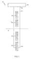
Fig. 1 is a schematic illustration of a sensor device having a plurality of vapor sensors and a plurality of liquid sensors according to one embodiment of the present invention. -
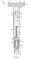
Fig. 2 is a schematic illustration of a sensor device having a plurality of vapor sensors and a plurality of liquid sensors according to another embodiment of the present invention. -
Fig. 3 is a flow chart of the sensor device's electronics according to one embodiment of the present invention. -
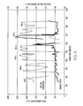
Fig. 4 is a graph showing the liquid sensor output versus temperature relationship according to the present invention. -
Fig. 5 is a graph showing the vapor sensor output versus temperature relationship according to the present invention. -
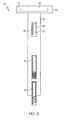
Fig. 6 is a schematic illustration of the plurality of liquid sensors in another embodiment according to the present invention. -
Fig. 7 is a schematic illustration of using one embodiment of the present invention to measure viscosity. - Referring to
Fig. 1 , the present invention is asensor device 10 that includes a plurality ofliquid sensors 20 and a plurality ofvapor sensors 30 that when used in conjunction with one another, can provide a thorough evaluation of the fluid to monitor the condition of the fluid. By providingliquid sensors 20 andvapor sensors 30 on thesame sensor device 10, the present invention allows for a compact, efficient, and economically feasible manner to monitor the condition of a fluid directly inside the operating equipment, via an on-line/on-board sensor device. The sensor device is adapted to measure fluid level, viscosity, temperature, electrical conductivity, electrochemical activity, water contamination, wear metals, soot buildup, coolant contamination, fluid level, and combinations thereof. Furthermore, thesensor device 10 allows for the lengthening of fluid sampling intervals of the monitored piece of equipment. In addition, thesensor device 10 allows for lengthening the fluid change out intervals of different equipment with the insurance that the useful life of the fluid will not be exceeded due to overuse. Further, thesensor device 10 increases the capabilities of an equipment operator to detect abnormally operating equipment at an earlier stage. - The
sensors member 12 having a first member end 12a and a second member end 12b. In one embodiment,member 12 is made of a conductive material to match the composition of surrounding components such as cast iron, stainless steel, aluminum or any other suitable metal. Themember 12 may also be made of a nonconductive material such as tetrafluoroethylene, high density polyethylene, polyimide polymer used for circuit boards, any other plastic or composite material dimensionally and chemically stable at the operating temperature of the monitored equipment, and combinations thereof.Member 12 is sized to be accommodated in the conventional dipstick port used in engines or other operating equipment with a fluid reservoir for checking the level of the operating fluid, such as, for example, oil.Member 12 can be a conventional dipstick. - The number and type of sensors utilized by the
sensor device 10 can be preselected based on the degradation/contamination mechanisms of the equipment to be monitored. Thesensors member 12 in a manner such that the plurality ofliquid sensors 20 may be fully immersed in afluid 11 while the plurality ofvapor sensors 30 do not come into contact with the fluid. Therefore, thevapor sensors 30 only measure parameters of the vapor portion of the fluid. Theliquid sensors 20 measure the temperature and electrical properties of the fluid. In one embodiment, the electrical properties are measured using single electrode conductivity and triangular waveform voltammetry methods that are disclosed byU.S. Patent Nos. 5,933,016 and5,071,527 , respectively and the disclosures of which are herein incorporated by reference. Other electrical properties measured may also include capacitance, dielectric constant, and the like. - As shown in
Fig. 2 , theliquid sensors 20 can beconductive line surfaces 27 on anonconductive substrate 29, forming asensor array 28 and/or can be a series ofwire rods insulation 14 is placed in between theliquid sensors 20 and over portions of the wire rods that are exposed to the fluid. In one embodiment, thewire rods sensor array 28 comprises sensors that are spaced between about 0.001 mm to about 1 mm apart, and more specifically about 0.075 mm apart. Theliquid sensors 20 can be comprised of any suitable corrosive resistant, conductive material. Suitable materials include, but are not limited to, glassy carbon, platinum, gold, copper, copper alloys, nickel alloys, stainless steels, and combinations thereof. In one embodiment, the liquid sensors are made of nickel or 316 stainless steel. Theinsulation 14 andnonconductive substrate 29 can comprise tetrafluoroethylene, high density polyethylene, polyimide polymer used for circuit boards, alumina, any other nonconductive material dimensionally and chemically stable in the fluid environment of the operating equipment, and combinations thereof. - Referring to
Fig. 2 , the plurality ofvapor sensors 30 contact only the fluid vapors, and are sensitive to fluid oxidation and/or condensing water droplets. Fluid oxidation orwater droplets 31 typically form after stopping the equipment, such as an engine, as compounds condense from the hot fluid onto a cooler portion of thesensor device 10, such as first member end 12a. Fluid oxidation or condensingwater droplets 31 can form while the engine is operating; in this case thevapor sensors 30 andliquid sensors 20 operate simultaneously. Therefore, when the engine shuts down or at any point when the fluid becomes sufficiently hot that oxidation products and/or water evaporates then condenses onto the cooler portion of thesensor device 10, condensingdroplets 31 form and adhere to thevapor sensors 30. The sensor then measures the vapor parameters. - Similar to the explanation provided above for the
liquid sensors 20, thevapor sensors 30 can beconductive line surfaces 27 provided on anonconductive substrate 29, forming an array sensor, and/or can be a series of wires (not shown). In one embodiment, theconductive line surfaces 27 and/or wires are placed between about 0.1 mm to about 50 mm apart from one another, and more specifically about 1 mm apart from one another. In one embodiment, the sensor array comprises sensors that are spaced between about 0.001 mm to about 1 mm apart, and more specifically about 0.075 mm apart. Thevapor sensors 30 can be comprised of any suitable corrosive resistant, conductive material. Suitable materials include, but are not limited to, glassy carbon, platinum, gold, copper, copper alloys, nickel alloys, copper alloys, stainless steel, and combinations thereof. In one embodiment, thevapor sensors 30 are made of nickel or 316 stainless steel. In one embodiment,insulation 14 is placed in between thevapor sensors 30 and over areas of the sensor not exposed to the fluid vapors. Theinsulation 14 and thenonconductive substrate 29 can be tetrafluoroethylene, high density polyethylene, polyimide polymer used for circuit boards, alumina, any other nonconductive material dimensionally and chemically stable in the fluid environment of the operating equipment, and combinations thereof. - Referring to
Figs. 2 and3 , anelectronic system 40 is coupled to thefirst member end 12a ofsensor device 10. Theelectronic system 40 is electrically connected to thesensors electronic system 40 includes the electronics for thesensors 41, areadout display 42 and areset button 44. Theelectronics 41 include apower source 60 which provides power to the central processing unit 62 (CPU),memory 64,data port 66, and thedisplay system 72. Thedisplay system 72 includes thedisplay driver 68 and thedisplay 42. Theelectronics 41 calculate the condition or level of the fluid by using an algorithm based on the degradation/contamination mechanism being monitored and the measurements taken from thevapor 30 andliquid sensor 20 outputs. TheCPU 62 uses the algorithm stored inmemory 64, and information supplied to it from thedata port 66 viasensors 20 and/or 30 to calculate the measurements for conditions that are being monitored. It is to be appreciated thatdata port 66 includes the necessary electronics to convert analog data fromsensors 20 and/or 30 into filtered, digital information in a format suitable for handling by theCPU 62. TheCPU 62 relays the calculated measurement(s) to thedisplay driver 68. Thedisplay driver 68 then formats the measurement(s) to thedisplay 42 such that the user may view it. The computations performed by theCPU 62 include the determination of accelerated oxidative degradation due to end of useful life or abnormal operating conditions, coolant/water contamination, soot build-up, viscosity change, accelerated wear, thermal breakdown of additives due to fires or hot spots and fluid level. - It is to be appreciated that power for the
electronics 41 may be supplied by an external source, or an intended battery. Additionally, computer algorithms and other initialization data may be loaded into thememory 64 from anexternal computer 70 also viadata port 66, if so desired. Furthermore, sensor data and computed measurements can be provided to theexternal computer 70 directly, from theCPU 62,sensors 20 and/or 30, and/ormemory 64 viadata port 66, if so desired. For example,computer 70 may be communicably coupled to theelectronics 41 via a cable connection, network connection, or via a wireless technology such as radio frequency wireless. - The
reset button 44 is located anywhere on the display system and may be pressed when the fluid is changed so that the device can reset the time being recorded and recognize sudden change in readings due to the fluid change. By attaching theelectronic system 40 to themember 12, thesensor device 10 provides the user a quick easy look at condition of the fluid. While theelectronic system 40 is shown coupled to thefirst member end 12a of themember 12, it is to be appreciated that thedisplay system 40 may be coupled to themember 12 in any area convenient for the user. - Referring again to
Fig. 2 , whenwire rods liquid sensors 20, the level of the fluid can be approximated by the following methodology. If thefluid contacts sensor 22 andsensor 23 the fluid completes the circuit between the two adjacent wire rods and the FULL light on thedisplay 42 illuminates. Thedisplay 42 is located on thedisplay system 40. However, if the fluid level is too low to contact thesensors contacts sensors display 42. When the fluid no longercontacts sensor 24 then the electrical circuit is broken and then ADD illuminates in thedisplay 42. The light system illustrated inFig. 2 could be replaced by a Liquid Crystal Display (LCD) with numerical/text readouts to conserve battery-life and to make the sensor output easier to modify. With a LCD a continuous, more accurate fluid level could be shown ondisplay 42. When the fluid completely submerges the entire exposed portions ofwire rods 26, the outputs ofwire rods 26 andarray 28 can be set to be equal anddisplay 42 can be set to read 100% full. If the oil level dropped then the output of thewire rods 26 would decrease proportionally but the output ofarray 28 would remain constant, still completely submerged. Therefore, the ratio of the output ofwire rod 26 to the output ofarray 28 could be shown bydisplay 42 as a percentage, e.g., 70%. This reading provides an accurate level reading and rate of level decrease, allowing for timely repairs when needed. It is to be appreciated that sensors other than wire rods can be used to indicate the fluid level; however, such alternative sensors should be completely submerged to accurately indicate the fluid level as full. - In another embodiment of the present invention, a
sensor array 28 having at least one magnetized line or a magnet is placed behind theliquid sensors 20 when using asensor array 28. The magnet or magnetized line helps thesensor array 28 to indicate the wear rate of the monitored equipment, such as an engine, on the fluid. As the magnet or magnetized line draws ferrous containing wear particles onto thesensor array 28, the sensor's output increases. When the deposited ferrous particles, and other metal particles associated with the ferrous wear debris, are in contact with both conductive lines onarray 28, the circuit is completed and the sensor is electrically shorted. The difference between the output of thesensor array 28 having a magnetic field attached (off-scale) and the output of asensor array 28 or otherliquid sensors 20 without a magnetic field (on-scale) is then attributed to the accelerated production of ferrous wear particles in the fluid by severe wear processes indicating maintenance action is necessary to repair the wearing part. Thesensor array 28 can then be removed to allow inspection of the collected debris to aid the user to identify the wearing part and the severity of the wear mechanism, i.e., the composition and size of the particles. The magnet or magnetized lines can be, Alnico which is a special aluminum-nickel-cobalt alloy, a ceramic such as barium or strontium ferrite, or a rare earth magnet such as Neodymium iron boron or samarium cobalt, or any other permanent magnet that retains its magnetism to temperatures above 700° F. - Applied voltage waveforms, such as square, sine, and triangular waveforms, may be applied to the fluid to increase the sensitivity of the
sensor device 10. The square or sine waveforms typically occur between about ±0.5 V and ±15V, specifically at ±3 V. The cycle rates are typically less than 1000 Hz, specifically at 1Hz for conductivity and 500 Hz for capacitance. Using a square or sine waveform of ±3V and 1 Hz for conductivity measurements in conjunction with thesensor device 10 increases the sensitivity of thesensor device 10 to oxidative degradation of the fluid. Using a square or sine waveform of ±3V and 500Hz for capacitance and dielectric constant measurements in conjunction withsensor 10 increases the sensitivity of thesensor device 10 to the soot build-up and other contaminants affecting the ability of the fluid to hold an electrical charge. The triangular waveform typically occurs between ±1 and ±20 V, specifically at ±15 V and at cycle rates between 0.001 and 100Hz, specifically 0.06 Hz. Using a triangular waveform in conjunction with thesensor device 10 causes electrolysis of the water with a resulting increase in current flow. This increase in current flow increases the sensor device's 10 sensitivity to water. The applied voltage waveforms may be supplied to the fluid by any suitable waveform generator. - Taking the sensor measurements in the liquid at different temperatures further increases the condition monitoring capabilities of the
sensor device 10. For example, after the fresh oil is added to an engine, the sensor output should increase linearly or in a consistent manner with the fresh oil's temperature, indicating that the fluid is not oxidized. As the oil becomes oxidized, theliquid sensors 20 increase exponentially with temperature. Thus, the deviation from the normal linear increase from the fresh oil plot versus the temperature increase of the oxidized oil is proportional to the degree of oxidation. After a fluid change, the increase in sensor output can be established for set temperatures for the fresh oil. The established output is compared to previous fresh oil readings to ensure the proper oil was used for the change out. An algorithm can be created from the data to calculate the measurement of the output. -
Fig. 4 is a graph showing a sensor output versus temperature relationship for an aircraft engine accelerated oxidation test and is indicative of the degree of oxidation. In particular, the graph indicates that as the temperature increases, the output of the liquid sensor also increases.Engine Run 8 indicates the beginning of oxidation by showing outputs of liquid sensors increasing slightly with the increasing of the oil temperature as illustrated along the y-axis. The temperature of the oil increased from 260° F (4400 RPM) up to 420° F (9900 RPM) which resulted in an increase in the outputs ofliquid sensors # 1 and #2 by less than 50%. However, byEngine Run 10 as temperature increases, the outputs of the liquid sensors increased by greater than 400%. For some high temperature equipment, such as aircraft engines which undergo frequent fresh oil additions, an increase in the liquid sensor output of 50% at a preset temperature or temperature increase is considered abnormal and indicative of engine problems, i.e., cracked seal. - The rate of increase is also important. If the liquid sensor output goes from normal to off-scale in a matter of minutes, the sudden increase is indicative of a hot spot or an engine fire. For other lower temperature equipment such as diesel engines, which undergo infrequent oil additions, an increase in the liquid sensor output of 200% at a preset temperature would be tolerable and be indicative of the need for an oil change rather than an engine problem.
- Taking the vapor readings as well as the liquid readings further increases the fluid condition monitoring capabilities of
sensor 10. As opposed to theliquid sensor 20 readings which can be affected by detergents, antioxidants and other strongly polar additives formulated into the fluid, the vapor sensor readings are only affected by volatile oxidation compounds and where applicable, water condensation and smoke. An algorithm can be created from the data to calculate the measurement of the output. - As shown in
Fig. 5 the vapor sensor readings provide an unchanged baseline until oil begins to oxidize. At the end ofengine run 9 according to liquid sensors inFig. 4 , the oil is starting to oxidize as indicated by the increased output by the sensor. As opposed to the liquid sensor readings, which increase with oxidation and temperature regardless of degree of oil oxidation, the vapor sensor readings only increase when accelerated oil oxidation is occurring. The output increases as the sensor environment cools, and/or the volatile compounds condense. As opposed to oxidation products, if the vapor sensors of an aircraft engine or other high temperature application rapidly go off-scale while the equipment is operating, additive degradation products from a hot spot or smoke from a fire has been detected requiring immediate attention by the equipment operator to avoid severe component damage and equipment failure. Vapor sensors only have an output when accelerated oxidation or abnormal operating conditions are occurring and are independent of fluid composition or additive package. - Referring to
Fig. 6 , thesensor device 10 another embodiment of the present invention can measure viscosity in a stagnant system. In such an embodiment, themember 12 is placed in an area where the fluid flow, such as for example, in valves or chambers. The rate at which the fluid flows from one chamber to another, for example, through a supply line at shut down, can be used to estimate the viscosity of the in-service fluid. At shut down, as the fluid flows decrease and drain to an oil collection point, such as the oil pan,upper sensor 3 positioned in the engine becomes less covered by the fluid. This results in a decreased sensor output byupper sensor 3 as compared to the sensor output ofsensor 21, which remains submerged in the oil. The rate at which the output ofupper sensor 3 decreases with respect tosensor 21 is directly proportional to the viscosity of the fluid, i.e., the more viscous the oil, the slower the oil drains from the surface ofupper senor 3 and the slower the output ofupper sensor 3 decreases with respect to the output ofsensor 21. Using a lookup table and system temperature reading, which includes a sensor precalibrated with fluids of known viscosities at known temperatures, the viscosity of the fluid is determined. - Referring to
Fig. 7 , a method for measuring the viscosity in a flowing system is provided. Thesensor system 59 is calibrated with fluids of know viscosities at specific temperatures. Afirst sensor 54 is placed upstream of a flow restriction and asecond sensor 56 is placed downstream. As the viscosity of fluid flowing in the direction ofarrow 50 decreases, the pressure differential decreases betweenfluid pockets pocket 53 also decreases with respect to the fluid level in thefluid pocket 55. The output ofsensor 54 influid pocket 53 decreases with respect to the output ofsensor 56 influid pocket 55. The difference between the outputs ofsensors - The
liquid sensors 20 andvapor sensors 30 can also be used to detect the formation of insoluble coolant/water concentration in fluids. Liquid array sensors spaced less than 75 microns apart or array sensors spaced greater than 500 microns apart or wire rod sensors spaced greater than 1 mm apart are typically used to detect insoluble coolant/water. For example, when coolant leaks into oil, coolant/water dissolves into oil to about 300 - 500 ppm concentration, depending on variables such as, dispersant additives, basestock composition, temperature, etc and is undetected by the sensors. As coolant/water accumulates, coolant/water droplets form in the oil and, depending on the operating temperature, water evaporates from the oil into vapor. When the droplets in the oil impact the liquid sensor surface or the water vapor condenses onto the vapor sensor surface or between the wire rod sensors in the vapor, the droplets/water form a layer of coolant/water on the surface. When the length of the adhered film exceeds the array line spacing or bridges of the wire rod sensor spacing then the sensor is electrically shorted and goes off scale. As soon as the coolant/water becomes insoluble in the fluid, the liquid sensor will go off-scale which indicates that water concentration is greater than 300 -500 ppm. The amount of water in the fluid to cause shorting of the vapor sensors depends upon the vapor array or rod spacing, i.e., the smaller the spacing, the less condensate is needed to short the array as well as the fraction of total system water that condensates onto the vapor sensor. A baseline can be established to compare the measurement if continuous monitoring of the vapor sensor is deemed necessary. - The accumulation of soot in oils can be monitored by comparing the output of at least two of the liquid sensors. A filter or other means to separate the soot from the oil may be placed on top of the liquid array senor surface or around a liquid wire sensor so that only soot free oil can touch the sensor. At least one other sensor is not covered by the filter and is therefore exposed directly to soot containing oil. If the difference between the outputs of the filter covered sensor and the uncovered sensor remain unchanged with operating time, then the sensors are not detecting soot accumulation. If the uncovered sensor output increases with respect to the output of the covered sensor, then the increased difference between the senor outputs is indicative of, and proportional to, soot accumulation in the fluid. The mathematical relationships between the sensor output differences and the soot level in the oil are established through precalibration of the sensors or experience with the selected equipment.
Claims (21)
- A single sensor device (10) for monitoring multiple conditions of a fluid (11) while the fluid is disposed within an operating reservoir comprising:a dipstick (12);a plurality of liquid sensors (20) provided at various lengths along said dipstick (12) and each comprising at least two wires or wire rods (22, 23, 24, 26, 27) for measuring the temperature and electrical properties of the fluid (11), said at least two wires or wire rods (22, 23, 24, 26, 27) adapted to be immersed and in contact with the fluid (11) such that in use current may pass between said at least two wires or wire rods (22, 23, 24, 26, 27) through the fluid (11) to monitor the condition of the fluid (11); andcharacterised in that
a plurality of vapor sensors (30) are disposed within an operating fluid reservoir for measuring vapor parameters of the fluid (11) within the operating reservoir coupled to said dipstick (12), wherein said plurality of liquid sensors (20) and plurality of vapor sensors (30) are positioned a distance from one another so that said plurality of vapor sensors (30) do not contact the fluid (11). - A sensor device (10) as claimed in claim 1, wherein said plurality of liquid sensors (20) and said plurality of vapor sensors (30) are adapted to operate simultaneously.
- A sensor device (10) as claimed in claim 1, wherein said plurality of liquid sensors (20) further comprises at least one sensor array (28) of conductive surfaces (27).
- A sensor device (10) as claimed in claim 3, wherein said conductive surfaces (27) are spaced between about 0.001 mm to about 1 mm apart.
- A sensor device (10) as claimed in claim 1, wherein said at least two wire rods (22, 23, 24, 26) are spaced between about 0.1 mm and about 100 mm apart.
- A sensor device (10) as claimed in claim 1, wherein said plurality of vapor sensors (30) comprises at least two conductive line surfaces (27) provided on a nonconductive substrate (29).
- A sensor device (10) as claimed in claim 6, wherein said at least two conductive lines (27) are spaced between about 0.1 mm and about 50 mm apart.
- A sensor device (10) as claimed in claim 1, wherein said plurality of vapor sensors (30) comprises sensor arrays that are spaced between about 0.001 mm to about 1 mm apart.
- A sensor device (10) as claimed in claim 1, wherein said plurality of liquid sensors (20) are formed from a conductive material selected from the group consisting of glassy carbon, platinum, gold, copper, copper alloys, nickel alloys, stainless steel, and combinations thereof.
- A sensor device (10) as claimed in claim 1, wherein said plurality of vapor sensors (30) are formed from a conductive material selected from the group consisting of glassy carbon, platinum, gold, copper, copper alloys, nickel alloys, stainless steel, and combinations thereof.
- A sensor device (10) as claimed in claim 1, wherein said sensor device (10) is adapted to measure fluid level, viscosity, temperature, electrical conductivity, electrochemical activity, water contamination, wear metals, soot buildup, coolant contamination, fluid level, capacitance, and combinations thereof.
- A sensor device (10) as claimed in claim 1, wherein said dipstick (12) is coupled to a fluid (11), said fluid (11) is selected from the group consisting of lubricating oils, transmission fluids, hydraulic fluids, transformer oils, metal working fluids, cooking oils, and combinations thereof.
- A sensor device (10) as claimed in claim 1, wherein said sensor device (10) further comprises a magnet positioned behind at least one of said plurality of liquid sensors (20), said sensor device (10) is adapted to measure a difference between outputs of said one of the liquid sensors (20) having said magnet and remaining ones of said plurality of liquid sensors (20) without said magnet, said difference being indicative of equipment wear detected by the sensor device (10).
- A sensor device (10) as claimed in claim 13, wherein said magnet is a magnetized line of a material which retains its magnetism to temperatures above about 700°F (371°C).
- A sensor device (10) as claimed in claim 1, wherein said sensor device (10) further comprises an electronic system (40) coupled to said dipstick (12), said electronic system (40) comprises electronics (41) for said plurality of liquid sensors (20) and said plurality of vapor sensors (30), and a readout display (42).
- A method for monitoring multiple conditions of an operating fluid (11) comprising:providing a single sensor device (10) having a plurality of liquid sensors (20) and a plurality of vapor sensors (30) on a dipstick (12), said plurality of liquid sensors (20) for measuring the temperature and electrical properties of the fluid and said plurality of vapor sensors (30) for measuring the fluid parameters of the fluid within an operating reservoir;placing said dipstick (12) into the operating reservoir such that said plurality of liquid sensors (20) are immersed in and in contact with said fluid (11) and said plurality of vapor sensors (30) do not come in contact with said fluid (11);measuring at least one parameter of said fluid (11) by detecting current passing between conductive surfaces of each liquid sensor (20) through the fluid (11); anddetermining a condition of said fluid (11) selected from the group consisting of fluid level, viscosity, temperature, electrical conductivity, electrochemical activity, water contamination, wear metals, soot buildup, coolant contamination, capacitance, dielectric constant, and combinations thereof by analyzing measurements of said fluid (11) using an algorithm based on said measurements of said plurality of liquid sensors (20) and said plurality of vapor sensors (30).
- A method as claimed in claim 16, wherein said method further comprises applying a square waveform to said fluid (11).
- A method as claimed in claim 16, wherein said method further comprises applying a triangular waveform to said fluid (11).
- A method as claimed in claim 16, wherein said method further comprises applying a sine waveform to said fluid (11).
- A method as claimed in claim 16, wherein said method further comprises varying the temperature of the fluid (11).
- A method as claimed in claim 16, further comprises displaying said condition of said fluid (11).
Applications Claiming Priority (3)
| Application Number | Priority Date | Filing Date | Title |
|---|---|---|---|
| US10/260,754 US7043967B2 (en) | 2002-09-30 | 2002-09-30 | Sensor device for monitoring the condition of a fluid and a method of using the same |
| US260754 | 2002-09-30 | ||
| PCT/US2003/029473 WO2004031764A1 (en) | 2002-09-30 | 2003-09-22 | Fluid condition monitor |
Publications (2)
| Publication Number | Publication Date |
|---|---|
| EP1549942A1 EP1549942A1 (en) | 2005-07-06 |
| EP1549942B1 true EP1549942B1 (en) | 2008-07-16 |
Family
ID=32029769
Family Applications (1)
| Application Number | Title | Priority Date | Filing Date |
|---|---|---|---|
| EP03749766A Expired - Lifetime EP1549942B1 (en) | 2002-09-30 | 2003-09-22 | Fluid condition monitor |
Country Status (11)
| Country | Link |
|---|---|
| US (1) | US7043967B2 (en) |
| EP (1) | EP1549942B1 (en) |
| JP (1) | JP4221373B2 (en) |
| KR (1) | KR101014548B1 (en) |
| CN (1) | CN100445742C (en) |
| AT (1) | ATE401571T1 (en) |
| AU (1) | AU2003267293A1 (en) |
| CA (1) | CA2499397C (en) |
| DE (1) | DE60322241D1 (en) |
| IL (1) | IL167479A (en) |
| WO (1) | WO2004031764A1 (en) |
Cited By (1)
| Publication number | Priority date | Publication date | Assignee | Title |
|---|---|---|---|---|
| US10753192B2 (en) | 2014-04-03 | 2020-08-25 | Sensia Llc | State estimation and run life prediction for pumping system |
Families Citing this family (38)
| Publication number | Priority date | Publication date | Assignee | Title |
|---|---|---|---|---|
| DE10163760C5 (en) * | 2001-12-28 | 2012-02-02 | Ebro Electronic Gmbh & Co. Kg | Apparatus and method for measuring the condition of oils and fats |
| US6907353B2 (en) * | 2003-06-24 | 2005-06-14 | Delphi Technologies, Inc. | Apparatus and method for measuring fluid characteristics |
| DE102004016957B4 (en) * | 2004-04-06 | 2007-05-03 | Testo Ag | Measuring device for measuring the state of oils or fats |
| US7107828B2 (en) * | 2005-02-24 | 2006-09-19 | Daimlerchrysler Corporation | Method and code for controlling actuator responsive to oil pressure using oil viscosity measure |
| US7614302B2 (en) * | 2005-08-01 | 2009-11-10 | Baker Hughes Incorporated | Acoustic fluid analysis method |
| US7665347B2 (en) * | 2005-11-11 | 2010-02-23 | Ngk Spark Plug Co., Ltd. | Liquid state detecting apparatus |
| EP1955377B1 (en) * | 2005-12-03 | 2017-08-16 | Pentair Thermal Management LLC | Sensor for detecting organic liquids |
| US20080034847A1 (en) * | 2006-08-10 | 2008-02-14 | Golter Lee B | Appartus and method for content discrimination |
| US7908906B2 (en) * | 2006-08-29 | 2011-03-22 | International Business Machines Corporation | Fluidic test apparatus and method |
| FI20065575A0 (en) * | 2006-09-20 | 2006-09-20 | Moventas Oy | Method and apparatus for monitoring the condition of lubricating oil |
| US8007655B2 (en) * | 2007-07-24 | 2011-08-30 | Georgia Tech Research Corporation | Method and apparatus for measuring properties of weak electrolytic, organic fluids such as hydrocarbon-based fluids |
| DE102007036473A1 (en) * | 2007-08-01 | 2009-02-05 | Testo Ag | Device for measuring the state of a material to be measured, in particular of oils or fats |
| US7900507B2 (en) * | 2007-09-28 | 2011-03-08 | University Of Dayton | Device and method for monitoring the quality of an oil change and condition of engine oil from an oil change |
| DE102008014477B4 (en) | 2008-03-17 | 2018-08-30 | Testo Ag | Device for measuring the state of a material to be measured, in particular of oils or fats |
| US8187455B2 (en) * | 2008-07-18 | 2012-05-29 | Socomer Nv. | Voltammetric technique to determine the individual concentration of different antioxidants of the same class |
| KR101138335B1 (en) * | 2010-05-26 | 2012-04-25 | 삼성중공업 주식회사 | Inspection tank and heating system having the same |
| US20120200961A1 (en) * | 2011-02-08 | 2012-08-09 | Philippe Magnier | Electric transformer explosion prevention device provided with a liquid detector |
| CN102213712A (en) * | 2011-04-15 | 2011-10-12 | 陈晓林 | Micro-water online monitoring and remote transmission system of transformer |
| GB2490678A (en) * | 2011-05-10 | 2012-11-14 | Rolls Royce Plc | A gas turbine power plant cooling system controller |
| CA2898201C (en) * | 2012-01-16 | 2023-09-26 | Abram Scientific, Inc. | Methods, devices, and systems for measuring physical properties of fluid |
| WO2014209897A2 (en) * | 2013-06-25 | 2014-12-31 | Cummins Filtration Ip, Inc | Fluid quality monitoring and filtration system |
| ES2742200T3 (en) | 2014-06-30 | 2020-02-13 | Pitco Frialator Inc | System and method to detect oil quality |
| DE102014111263A1 (en) * | 2014-08-07 | 2016-03-10 | Endress+Hauser Flowtec Ag | Early warning system for condensation-induced water hammer |
| US9297686B1 (en) * | 2015-04-02 | 2016-03-29 | Texas Lfp, Llc | Liquid level transducer with insertable quality sensor |
| US9841394B2 (en) | 2015-11-16 | 2017-12-12 | Pitco Frialator, Inc. | System and method for sensing oil quality |
| US10436730B2 (en) | 2015-12-21 | 2019-10-08 | Pitco Frialator, Inc. | System and method for sensing oil quality |
| EP3211417A1 (en) * | 2016-02-23 | 2017-08-30 | C.C. Jensen A/S | System and sensor unit for monitoring and evaluation of the condition of a liquid |
| CN105823806A (en) * | 2016-05-17 | 2016-08-03 | 淮北师范大学 | Portable edible oil detecting device |
| US10379082B2 (en) | 2016-12-15 | 2019-08-13 | Caterpillar Inc. | System for monitoring machine fluids by measuring fluctuations in a magnetic field |
| KR101925014B1 (en) * | 2017-03-30 | 2018-12-04 | 한국과학기술원 | sensor apparatus and fence apparatus using the same |
| FR3082507B1 (en) * | 2018-06-14 | 2022-01-28 | Safran Aircraft Engines | DEVICE AND METHOD FOR DRAINING AND MONITORING DRAINED FLUID FROM AN AIRCRAFT ENGINE |
| US11307119B2 (en) | 2019-04-23 | 2022-04-19 | Pall Corporation | Aircraft air contaminant collector device and method of use |
| US11460444B2 (en) | 2019-04-23 | 2022-10-04 | Pall Corporation | Aircraft air contaminant analyzer and method of use |
| US10955318B2 (en) | 2019-04-23 | 2021-03-23 | Pall Corporation | Aircraft air contaminant analyzer and method of use |
| US11668677B2 (en) | 2019-04-23 | 2023-06-06 | Pall Corporation | Aircraft air contaminant analyzer and method of use |
| CN115702347A (en) * | 2020-06-01 | 2023-02-14 | 路博润公司 | Surface insulation resistance compatibility test system and method |
| US11668668B2 (en) * | 2020-10-05 | 2023-06-06 | Pryor Knowledge Systems, Inc. | Mechanism for the real-time prediction of incipient failure in working fluids |
| WO2023033860A1 (en) * | 2021-08-31 | 2023-03-09 | Tannas Company | Conductive deposit test apparatus and method |
Family Cites Families (22)
| Publication number | Priority date | Publication date | Assignee | Title |
|---|---|---|---|---|
| US3580263A (en) * | 1969-06-11 | 1971-05-25 | Chevron Res | Pressure liquid level indicator |
| US3710237A (en) * | 1970-09-08 | 1973-01-09 | Nalco Chemical Co | Probe for a conductivity testing device |
| FR2164975A5 (en) | 1971-12-13 | 1973-08-03 | Peugeot & Renault | |
| JPS5885314A (en) * | 1981-11-17 | 1983-05-21 | Nissan Motor Co Ltd | Deterioration detector of engine oil |
| US4601201A (en) * | 1984-03-14 | 1986-07-22 | Tokyo Tatsuno Co., Ltd. | Liquid level and quantity measuring apparatus |
| JPS6123780A (en) * | 1984-07-12 | 1986-02-01 | Kureha Chem Ind Co Ltd | Oxygen cathode for electrolyzing alkali chloride and its manufacture |
| US4692698A (en) * | 1985-08-12 | 1987-09-08 | Tribometrics, Inc. | Method and device including a bed of ferromagnetic fibers and magnetic flux sensor for measuring the amount of magnetic particles on a liquid |
| US4720997A (en) * | 1986-12-01 | 1988-01-26 | Doak Roni K | Material level monitor |
| US4764258A (en) * | 1986-12-23 | 1988-08-16 | University Of Dayton | Method for evaluating the remaining useful life of a hydrocarbon oil |
| US5071527A (en) * | 1990-06-29 | 1991-12-10 | University Of Dayton | Complete oil analysis technique |
| US5262732A (en) * | 1991-12-11 | 1993-11-16 | Computational Systems, Inc. | Oil monitor with magnetic field |
| US5485491A (en) | 1994-03-31 | 1996-01-16 | Westinghouse Electric Corporation | Online diagnostic system for rotating electrical apparatus |
| DE19511556C1 (en) * | 1995-03-29 | 1996-07-25 | Daimler Benz Ag | Electrical sensor for determn. of state of liq. in container |
| US5765994A (en) * | 1995-07-14 | 1998-06-16 | Barbier; William J. | Low oil detector with automatic reset |
| WO1997030930A2 (en) * | 1996-02-21 | 1997-08-28 | Cassiano Limited | Method and apparatus for adding fluid additives to fluids |
| US5933016A (en) * | 1996-08-30 | 1999-08-03 | The University Of Dayton | Single electrode conductivity technique |
| US6324899B1 (en) * | 1998-04-02 | 2001-12-04 | Reliance Electric Technologies, Llc | Bearing-sensor integration for a lubrication analysis system |
| US6202486B1 (en) * | 1998-10-01 | 2001-03-20 | Imaging & Sensing Technology Corporation | Analog liquid level sensor |
| US6128561A (en) * | 1998-11-16 | 2000-10-03 | Georgia Tech Research Corporation | Self-diagnostic system for conditioned maintenance of machines operating under intermittent load |
| US6615658B2 (en) * | 1999-08-03 | 2003-09-09 | Charles Darwin Snelling | Method and apparatus for detecting the internal liquid level in a vessel |
| US6278282B1 (en) * | 1999-10-07 | 2001-08-21 | Detroit Diesel Corporation | Method and system for determining oil quality |
| US6377052B1 (en) | 1999-11-03 | 2002-04-23 | Eaton Corporation | Monitoring fluid condition through an aperture |
-
2002
- 2002-09-30 US US10/260,754 patent/US7043967B2/en not_active Expired - Lifetime
-
2003
- 2003-09-22 CA CA2499397A patent/CA2499397C/en not_active Expired - Lifetime
- 2003-09-22 WO PCT/US2003/029473 patent/WO2004031764A1/en active Application Filing
- 2003-09-22 AT AT03749766T patent/ATE401571T1/en not_active IP Right Cessation
- 2003-09-22 JP JP2004541575A patent/JP4221373B2/en not_active Expired - Lifetime
- 2003-09-22 AU AU2003267293A patent/AU2003267293A1/en not_active Abandoned
- 2003-09-22 CN CNB038233282A patent/CN100445742C/en not_active Expired - Lifetime
- 2003-09-22 KR KR1020057005489A patent/KR101014548B1/en active IP Right Grant
- 2003-09-22 DE DE60322241T patent/DE60322241D1/en not_active Expired - Lifetime
- 2003-09-22 EP EP03749766A patent/EP1549942B1/en not_active Expired - Lifetime
-
2005
- 2005-03-16 IL IL167479A patent/IL167479A/en active IP Right Grant
Cited By (1)
| Publication number | Priority date | Publication date | Assignee | Title |
|---|---|---|---|---|
| US10753192B2 (en) | 2014-04-03 | 2020-08-25 | Sensia Llc | State estimation and run life prediction for pumping system |
Also Published As
| Publication number | Publication date |
|---|---|
| JP2006501472A (en) | 2006-01-12 |
| KR20050056220A (en) | 2005-06-14 |
| CN1685228A (en) | 2005-10-19 |
| US7043967B2 (en) | 2006-05-16 |
| JP4221373B2 (en) | 2009-02-12 |
| US20040060344A1 (en) | 2004-04-01 |
| CA2499397C (en) | 2011-01-18 |
| IL167479A (en) | 2009-09-22 |
| AU2003267293A1 (en) | 2004-04-23 |
| CN100445742C (en) | 2008-12-24 |
| WO2004031764A1 (en) | 2004-04-15 |
| ATE401571T1 (en) | 2008-08-15 |
| EP1549942A1 (en) | 2005-07-06 |
| KR101014548B1 (en) | 2011-02-16 |
| DE60322241D1 (en) | 2008-08-28 |
| CA2499397A1 (en) | 2004-04-15 |
Similar Documents
| Publication | Publication Date | Title |
|---|---|---|
| EP1549942B1 (en) | Fluid condition monitor | |
| US7043402B2 (en) | On-line oil condition sensor system for rotating and reciprocating machinery | |
| US5889200A (en) | Tandem technique for fluid monitoring | |
| US5933016A (en) | Single electrode conductivity technique | |
| US20100180663A1 (en) | Sensor and method for detecting oil deterioration and oil level | |
| CA2711951C (en) | Localized corrosion monitoring device for limited conductivity fluids | |
| EP2299159A2 (en) | Method for monitoring the condition of a gearbox and a corresponding arrangement | |
| WO2006078960A2 (en) | On-line monitoring of degredation and contamination of lubricant of rotating equipment | |
| WO2008014235A1 (en) | Oxidation stability measurement for oil | |
| KR20070011584A (en) | Method for on-line monitoring of condition of non-aqueous fluids | |
| US7900507B2 (en) | Device and method for monitoring the quality of an oil change and condition of engine oil from an oil change | |
| KR20070117832A (en) | Method for testing condition of lubricating oil | |
| Sanga et al. | Design and development of opto-resistive type quasi-digital sensor and instrument to in-situ monitoring of the quality of lubricant oil | |
| EP3999840A1 (en) | A triboelectrostatic sensor allowing instantaneous state of oils to be monitored and oil remaining lifetime detection method therefore | |
| Mobley | Condition based maintenance | |
| WO2007145529A1 (en) | Fluid analysing system technology | |
| Sheldon et al. | Combining Oil Health, Level, and Vibration to Achieve Complete Machine Monitoring | |
| Mauntz et al. | Condition based maintenance of wind turbines by 24/7 monitoring of oil quality and additive consumption: Identi-fication of critical operation conditions and determination of the next oil change | |
| JP3602782B2 (en) | Degradation degree measuring kit and method for diagnosing deterioration life of electronic circuit board using this deterioration degree measuring kit | |
| Mauntz et al. | Condition Based Maintenance of Wind Turbines by 24/7 Monitoring of Oil Quality, Oil Aging and Additive Consumption: Identification of critical operation conditions & determination of the next oil exchange | |
| CN116953038A (en) | Ship main engine lubricating oil product analysis and monitoring method | |
| Okhlopkov et al. | Analysis of Existing Methods for Detecting the State and Defects of the Brush-Contact Device of a Turbine Generator | |
| KR20110052074A (en) | The sensor system for detecting of lubrication oil condition by on line check | |
| JPH08313517A (en) | Lubrication oil deterioration monitoring device | |
| Woodley | Failure prediction by condition monitoring (part 1) |
Legal Events
| Date | Code | Title | Description |
|---|---|---|---|
| PUAI | Public reference made under article 153(3) epc to a published international application that has entered the european phase |
Free format text: ORIGINAL CODE: 0009012 |
|
| 17P | Request for examination filed |
Effective date: 20050503 |
|
| AK | Designated contracting states |
Kind code of ref document: A1 Designated state(s): AT BE BG CH CY CZ DE DK EE ES FI FR GB GR HU IE IT LI LU MC NL PT RO SE SI SK TR |
|
| AX | Request for extension of the european patent |
Extension state: AL LT LV MK |
|
| R17P | Request for examination filed (corrected) |
Effective date: 20050428 |
|
| DAX | Request for extension of the european patent (deleted) | ||
| GRAP | Despatch of communication of intention to grant a patent |
Free format text: ORIGINAL CODE: EPIDOSNIGR1 |
|
| GRAS | Grant fee paid |
Free format text: ORIGINAL CODE: EPIDOSNIGR3 |
|
| GRAA | (expected) grant |
Free format text: ORIGINAL CODE: 0009210 |
|
| AK | Designated contracting states |
Kind code of ref document: B1 Designated state(s): AT BE BG CH CY CZ DE DK EE ES FI FR GB GR HU IE IT LI LU MC NL PT RO SE SI SK TR |
|
| REG | Reference to a national code |
Ref country code: GB Ref legal event code: FG4D |
|
| REG | Reference to a national code |
Ref country code: CH Ref legal event code: EP |
|
| REF | Corresponds to: |
Ref document number: 60322241 Country of ref document: DE Date of ref document: 20080828 Kind code of ref document: P |
|
| REG | Reference to a national code |
Ref country code: IE Ref legal event code: FG4D |
|
| NLV1 | Nl: lapsed or annulled due to failure to fulfill the requirements of art. 29p and 29m of the patents act | ||
| PG25 | Lapsed in a contracting state [announced via postgrant information from national office to epo] |
Ref country code: NL Free format text: LAPSE BECAUSE OF FAILURE TO SUBMIT A TRANSLATION OF THE DESCRIPTION OR TO PAY THE FEE WITHIN THE PRESCRIBED TIME-LIMIT Effective date: 20080716 Ref country code: ES Free format text: LAPSE BECAUSE OF FAILURE TO SUBMIT A TRANSLATION OF THE DESCRIPTION OR TO PAY THE FEE WITHIN THE PRESCRIBED TIME-LIMIT Effective date: 20081027 Ref country code: PT Free format text: LAPSE BECAUSE OF FAILURE TO SUBMIT A TRANSLATION OF THE DESCRIPTION OR TO PAY THE FEE WITHIN THE PRESCRIBED TIME-LIMIT Effective date: 20081216 |
|
| PG25 | Lapsed in a contracting state [announced via postgrant information from national office to epo] |
Ref country code: SI Free format text: LAPSE BECAUSE OF FAILURE TO SUBMIT A TRANSLATION OF THE DESCRIPTION OR TO PAY THE FEE WITHIN THE PRESCRIBED TIME-LIMIT Effective date: 20080716 Ref country code: AT Free format text: LAPSE BECAUSE OF FAILURE TO SUBMIT A TRANSLATION OF THE DESCRIPTION OR TO PAY THE FEE WITHIN THE PRESCRIBED TIME-LIMIT Effective date: 20080716 Ref country code: FI Free format text: LAPSE BECAUSE OF FAILURE TO SUBMIT A TRANSLATION OF THE DESCRIPTION OR TO PAY THE FEE WITHIN THE PRESCRIBED TIME-LIMIT Effective date: 20080716 Ref country code: BG Free format text: LAPSE BECAUSE OF FAILURE TO SUBMIT A TRANSLATION OF THE DESCRIPTION OR TO PAY THE FEE WITHIN THE PRESCRIBED TIME-LIMIT Effective date: 20081016 |
|
| PG25 | Lapsed in a contracting state [announced via postgrant information from national office to epo] |
Ref country code: BE Free format text: LAPSE BECAUSE OF FAILURE TO SUBMIT A TRANSLATION OF THE DESCRIPTION OR TO PAY THE FEE WITHIN THE PRESCRIBED TIME-LIMIT Effective date: 20080716 |
|
| PG25 | Lapsed in a contracting state [announced via postgrant information from national office to epo] |
Ref country code: MC Free format text: LAPSE BECAUSE OF NON-PAYMENT OF DUE FEES Effective date: 20080930 Ref country code: EE Free format text: LAPSE BECAUSE OF FAILURE TO SUBMIT A TRANSLATION OF THE DESCRIPTION OR TO PAY THE FEE WITHIN THE PRESCRIBED TIME-LIMIT Effective date: 20080716 Ref country code: DK Free format text: LAPSE BECAUSE OF FAILURE TO SUBMIT A TRANSLATION OF THE DESCRIPTION OR TO PAY THE FEE WITHIN THE PRESCRIBED TIME-LIMIT Effective date: 20080716 |
|
| REG | Reference to a national code |
Ref country code: CH Ref legal event code: PL |
|
| PLBE | No opposition filed within time limit |
Free format text: ORIGINAL CODE: 0009261 |
|
| STAA | Information on the status of an ep patent application or granted ep patent |
Free format text: STATUS: NO OPPOSITION FILED WITHIN TIME LIMIT |
|
| PG25 | Lapsed in a contracting state [announced via postgrant information from national office to epo] |
Ref country code: SK Free format text: LAPSE BECAUSE OF FAILURE TO SUBMIT A TRANSLATION OF THE DESCRIPTION OR TO PAY THE FEE WITHIN THE PRESCRIBED TIME-LIMIT Effective date: 20080716 Ref country code: RO Free format text: LAPSE BECAUSE OF FAILURE TO SUBMIT A TRANSLATION OF THE DESCRIPTION OR TO PAY THE FEE WITHIN THE PRESCRIBED TIME-LIMIT Effective date: 20080716 Ref country code: CZ Free format text: LAPSE BECAUSE OF FAILURE TO SUBMIT A TRANSLATION OF THE DESCRIPTION OR TO PAY THE FEE WITHIN THE PRESCRIBED TIME-LIMIT Effective date: 20080716 |
|
| 26N | No opposition filed |
Effective date: 20090417 |
|
| REG | Reference to a national code |
Ref country code: IE Ref legal event code: MM4A |
|
| PG25 | Lapsed in a contracting state [announced via postgrant information from national office to epo] |
Ref country code: IE Free format text: LAPSE BECAUSE OF NON-PAYMENT OF DUE FEES Effective date: 20080922 |
|
| PG25 | Lapsed in a contracting state [announced via postgrant information from national office to epo] |
Ref country code: IT Free format text: LAPSE BECAUSE OF FAILURE TO SUBMIT A TRANSLATION OF THE DESCRIPTION OR TO PAY THE FEE WITHIN THE PRESCRIBED TIME-LIMIT Effective date: 20080716 |
|
| PG25 | Lapsed in a contracting state [announced via postgrant information from national office to epo] |
Ref country code: LI Free format text: LAPSE BECAUSE OF NON-PAYMENT OF DUE FEES Effective date: 20080930 Ref country code: CH Free format text: LAPSE BECAUSE OF NON-PAYMENT OF DUE FEES Effective date: 20080930 |
|
| PG25 | Lapsed in a contracting state [announced via postgrant information from national office to epo] |
Ref country code: SE Free format text: LAPSE BECAUSE OF FAILURE TO SUBMIT A TRANSLATION OF THE DESCRIPTION OR TO PAY THE FEE WITHIN THE PRESCRIBED TIME-LIMIT Effective date: 20081016 |
|
| PG25 | Lapsed in a contracting state [announced via postgrant information from national office to epo] |
Ref country code: LU Free format text: LAPSE BECAUSE OF NON-PAYMENT OF DUE FEES Effective date: 20080922 Ref country code: HU Free format text: LAPSE BECAUSE OF FAILURE TO SUBMIT A TRANSLATION OF THE DESCRIPTION OR TO PAY THE FEE WITHIN THE PRESCRIBED TIME-LIMIT Effective date: 20090117 Ref country code: CY Free format text: LAPSE BECAUSE OF FAILURE TO SUBMIT A TRANSLATION OF THE DESCRIPTION OR TO PAY THE FEE WITHIN THE PRESCRIBED TIME-LIMIT Effective date: 20080716 |
|
| PG25 | Lapsed in a contracting state [announced via postgrant information from national office to epo] |
Ref country code: TR Free format text: LAPSE BECAUSE OF FAILURE TO SUBMIT A TRANSLATION OF THE DESCRIPTION OR TO PAY THE FEE WITHIN THE PRESCRIBED TIME-LIMIT Effective date: 20080716 |
|
| PG25 | Lapsed in a contracting state [announced via postgrant information from national office to epo] |
Ref country code: GR Free format text: LAPSE BECAUSE OF FAILURE TO SUBMIT A TRANSLATION OF THE DESCRIPTION OR TO PAY THE FEE WITHIN THE PRESCRIBED TIME-LIMIT Effective date: 20081017 |
|
| REG | Reference to a national code |
Ref country code: FR Ref legal event code: PLFP Year of fee payment: 14 |
|
| REG | Reference to a national code |
Ref country code: FR Ref legal event code: PLFP Year of fee payment: 15 |
|
| REG | Reference to a national code |
Ref country code: FR Ref legal event code: PLFP Year of fee payment: 16 |
|
| PGFP | Annual fee paid to national office [announced via postgrant information from national office to epo] |
Ref country code: GB Payment date: 20220927 Year of fee payment: 20 Ref country code: DE Payment date: 20220928 Year of fee payment: 20 |
|
| PGFP | Annual fee paid to national office [announced via postgrant information from national office to epo] |
Ref country code: FR Payment date: 20220926 Year of fee payment: 20 |
|
| REG | Reference to a national code |
Ref country code: DE Ref legal event code: R071 Ref document number: 60322241 Country of ref document: DE |
|
| REG | Reference to a national code |
Ref country code: GB Ref legal event code: PE20 Expiry date: 20230921 |
|
| PG25 | Lapsed in a contracting state [announced via postgrant information from national office to epo] |
Ref country code: GB Free format text: LAPSE BECAUSE OF EXPIRATION OF PROTECTION Effective date: 20230921 |