EP1549123A1 - Système de ventilation pour un appareillage électrique ou électronique - Google Patents
Système de ventilation pour un appareillage électrique ou électronique Download PDFInfo
- Publication number
- EP1549123A1 EP1549123A1 EP04292860A EP04292860A EP1549123A1 EP 1549123 A1 EP1549123 A1 EP 1549123A1 EP 04292860 A EP04292860 A EP 04292860A EP 04292860 A EP04292860 A EP 04292860A EP 1549123 A1 EP1549123 A1 EP 1549123A1
- Authority
- EP
- European Patent Office
- Prior art keywords
- primary
- ventilation system
- air
- cavities
- source
- Prior art date
- Legal status (The legal status is an assumption and is not a legal conclusion. Google has not performed a legal analysis and makes no representation as to the accuracy of the status listed.)
- Granted
Links
- 238000009423 ventilation Methods 0.000 title claims abstract description 37
- 238000005192 partition Methods 0.000 claims description 13
- 238000001816 cooling Methods 0.000 claims description 12
- 239000003570 air Substances 0.000 description 59
- 230000015556 catabolic process Effects 0.000 description 4
- 239000012530 fluid Substances 0.000 description 4
- 230000001174 ascending effect Effects 0.000 description 3
- 238000000605 extraction Methods 0.000 description 3
- 230000000694 effects Effects 0.000 description 2
- BASFCYQUMIYNBI-UHFFFAOYSA-N platinum Chemical compound [Pt] BASFCYQUMIYNBI-UHFFFAOYSA-N 0.000 description 2
- 239000012080 ambient air Substances 0.000 description 1
- 230000015572 biosynthetic process Effects 0.000 description 1
- 229910052697 platinum Inorganic materials 0.000 description 1
- 238000000638 solvent extraction Methods 0.000 description 1
- 238000013022 venting Methods 0.000 description 1
Images



Classifications
-
- H—ELECTRICITY
- H05—ELECTRIC TECHNIQUES NOT OTHERWISE PROVIDED FOR
- H05K—PRINTED CIRCUITS; CASINGS OR CONSTRUCTIONAL DETAILS OF ELECTRIC APPARATUS; MANUFACTURE OF ASSEMBLAGES OF ELECTRICAL COMPONENTS
- H05K7/00—Constructional details common to different types of electric apparatus
- H05K7/20—Modifications to facilitate cooling, ventilating, or heating
- H05K7/20009—Modifications to facilitate cooling, ventilating, or heating using a gaseous coolant in electronic enclosures
- H05K7/20136—Forced ventilation, e.g. by fans
- H05K7/2019—Fan safe systems, e.g. mechanical devices for non stop cooling
Definitions
- the invention relates to the cooling of electrical or electronic equipment.
- the invention relates to a system of ventilation for electrical equipment or electronics installed in an enclosure of a housing in which one wishes to create a movement then an extraction of air for cooling the equipment in operation.
- the invention aims to remedy in particular the disadvantages mentioned above by proposing a system of ventilation that allows for cooling to the efficient and uniform use of electrical equipment or even when a breakdown occurs up to 50% of the capacity of the ventilation system.
- the invention proposes, according to a first aspect, a ventilation system of an apparatus electrical or electronic installed in an enclosure of a housing having an air inlet and an air outlet for create an air flow in said enclosure, which has at least two sources of air suction, know a primary source and a secondary source, as well a box intended to be mounted on said housing of the side of the air outlet, this box defining at least two partitioned cavities, intended to be connected both at the air outlet, namely a cavity primary, connected to the primary source, and a cavity secondary, connected to the secondary source.
- both sources of suction When both sources of suction are operational, that is, when the system of ventilation can operate at full capacity, the air is sucked jointly by both sources.
- the circuits exhaust air being separated through the partitioning cavities, there is no risk of charge transfer from one circuit to another. This results in operation autonomous of each of the sources of aspiration, for the benefit of the reliability of the ventilation system.
- the box defines two nested cavities, separated by a partition keep on going.
- the cavities are preferably symmetrical; they present for example a symmetry Central.
- the partition extends in a pattern crenellated, each cavity having the shape of a comb.
- the box comprises a plurality of primary cavities and a plurality of alternate secondary cavities, cavities primary sources being connected to the primary source and cavities secondary to the secondary source.
- the cavities are separated by a plurality of parallel partitions that isolate the cavities primary secondary cavities.
- the box defines a primary chamber through which the or each primary cavity is connected fluidically to the primary source, and a chamber secondary school through which the or each secondary cavity is fluidly connected to the source secondary.
- the box preferably comprises a wall separating each cavity from the corresponding chamber, said wall being provided with at least one primary opening by which the primary cavity communicates with the chamber primary and at least one secondary opening which the secondary cavity communicates with the chamber secondary.
- Each suction source is for example a fan, mounted on the box.
- each suction source comprises a turbine.
- the invention proposes a apparatus for cooling an electrical equipment or electronic, which comprises a housing defining a enclosure intended to receive said apparatus, this housing having an air inlet and an air outlet for create an air flow in said enclosure, as well as ventilation system with at least two sources of air suction, namely a primary source and a secondary source, as well as a box mounted on said housing on the side of the air outlet, this box defining at least two partitioned cavities, connected both at the air outlet, namely a cavity primary source, connected to said primary source, and a secondary cavity, connected to said secondary source.
- the air outlet of the housing is for example formed by a perforated upper wall.
- the cavities jointly cover the entire surface of the air outlet so as to maximize the flow of air exhausted from sources suction.
- FIG. 1 an apparatus 1 for the cooling of electrical equipment or electronic.
- This apparatus 1 comprises a housing 2 parallelepipedal, for example metallic, or metallized in the event of electromagnetic protection should be ensured, housing 2 which has a wall lower 3, by which the housing 2 rests on a support (not shown), and a top wall 4 opposite, connected by side walls 5, 6, three of which 5 are blind and one of which, said front wall 6, is provided with an opening 7.
- the walls 5, 6 of the housing 2 define together an enclosure 8 in which is placed, after being introduced through the opening 7, electrical or electronic equipment, which may be constituted by a plurality of cards carrying circuits integrated, for example to ensure the control of autopilot of an aircraft.
- the wall bottom 3 of the housing 2 is provided with a plurality of perforations 9 which connect the speaker 8 with ambient air to form an air inlet.
- the upper wall 4 is provided with a plurality of perforations 11 which, opposite the lower wall 3, form an air outlet 12 to create, together with the air inlet 10, an air flow in the enclosure 8, intended for cooling the electrical equipment or electronic.
- the support on which the housing 2 is placed can be equipped with integrated ventilation connected to the power supply of the room in which the apparatus 1 is placed, in this case the general power supply of the aircraft. Where such ventilation exists, it may be prone to breakdowns. So is it proposed to equip the apparatus 1 of an air extraction system 13 for ensure forced ventilation of the enclosure 8.
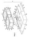
- This air extraction system 13 comprises at least two sources suck air, in this case formed respectively by two fans 14, 15 (two exactly in the example shown in Figures 1 and 2), namely a primary fan 14 and a fan secondary 15, mounted on a box 16 fixed in turn on the housing 2 on the side of the upper wall 4 which he covers the air outlet 12.
- This box 16 is designed to generate two circuits separated from the evacuation of the air at the outlet of the enclosure 8, namely a primary circuit passing through the fan primary 14 and a secondary circuit crossing the secondary fan 15. We will see below how these two circuits are made.
- the box has a bottom wall 17 substantially parallel to the upper wall 4 of the housing 2, bordered by a skirt 18 which extends projecting towards the housing 2, and thanks to which the box 16 can fit on the housing 2.
- the wall 17 and the skirt 18 jointly define a volume 19 which, when the casing 16 is fixed on the housing 2, overlooking the air outlet 12.
- volume 19 is divided into at least two cavities 20, 21 separated by a partition 22 joining two opposite edges 23, 24 or 25, 26 of the skirt 18, this partition 22 forming protruding from the bottom wall 17.
- This partition 22 has an end surface 27 turned to the opposite of the wall 17 and which, when the casing 16 is mounted on the housing 2, is applied against the upper wall 4 of it.
- the partition 22 isolates the primary cavity 20 of the secondary cavity 21, the air can not circulate directly from one to the other.
- the box 16 defines moreover, on the upper side of the wall 17-that is to say on the opposite side to the cavities 20, 21-, two chambers 28, 29, namely a primary chamber 28 to which is fluidically connected the primary fan-14 and by which transits the air of the primary circuit, and a secondary chamber 29 to which is connected fluidically the secondary fan 15 and by which is intended to transit the air of the secondary circuit.
- chambers 28, 29 are isolated from each other by a partition wall 30 projecting from the wall 17, on the side superior of it.
- the chambers 28, 29 are bordered by side walls 31a, 31b, 31c and 32a, 32b, 32c which project from the side top of the bottom wall 17 and are surmounted by a upper wall 33 in which are practiced two windows 34, 35, namely a primary window 34 giving access to the primary chamber 28 and a secondary window 35 giving access to the secondary chamber 29.
- each fan 14, 15 comprises a housing 36 in which a rotor 37 is rotatably mounted about an axis X fixed by compared to the housing 36.
- Each housing 36 has a substantially cylindrical side wall 38 which extends parallel to the X axis of the rotor 37 and one end bottom 39 is shaped in platinum by which the housing 36 is fixed to the casing 16 (for example by screwing), coming to cover the window 34, 35 corresponding.
- the fans 14, 15 are axial fans (that is, they are venting the air parallel to their X axis of rotation), but it could be turbines, evacuating the air perpendicular to their X axis.
- the air of the primary circuit passes, at the exit housing 2, through the primary cavity 20, passes through the primary openings 43, passes through the primary chamber 28 before being expelled by the primary fan.
- the air of the secondary circuit passes meanwhile, at the output of the housing 2, through the secondary cavity 21, transits through the secondary openings 44, passes through the chamber secondary 29 before being expelled by the fan secondary.
- box 17 according to the number and shape of the cavities 20, 21.
- the casing 17 comprises exactly two cavities 20, 21 which, each having the shape of a comb, are nested one inside the other by being separated by a continuous partition 22 extending along a crenellated motif.
- the fan secondary 15 When one of the fans-for example the primary fan 14- breaks down, the fan secondary 15 generates in the enclosure 8 air layers ascending which, through inertia, they have an air movement, also ascending, which rushes through the perforations 9 into the cavity primary 20 to be evacuated following the circuit primary, despite the shutdown of the fan 14 corresponding. And, as the perforations 11 generate losses, there is no risk that within the enclosure 8 a loop circulation of the air.
- each circuit air has a sufficient flow.
- several primary openings 43 and 44 are formed in the wall 17.
- a row of four primary openings 43a, 43b, 43c, 43d are provided in the wall 17 to place the cavity in communication primary 20 and the primary chamber 28, and a row of four secondary openings 44a, 44b, 44c, 44d are provided in the wall 17 to port the secondary cavity 21 and the secondary chamber 29.
- the primary openings 43a, 43b, 43c, 43d and secondary 44a, 44b, 44c, 44d are respectively grouped in two diagonally opposite corners of the wall 17, but could spread them more evenly along it.
- the cavities 20, 21 are symmetrical with respect to the other. More precisely, they present a symmetry center with respect to a median axis of the casing 16, perpendicular to the wall 17.
- the casing 16 comprises a plurality of primary cavities 20a, 20b, 20c, 20d and a plurality of secondary cavities 21a, 21b, 21c, 21d, alternating, separated two by two by a plurality of partitions 22a to 22g parallel -linear in this case- that connect two opposite edges 25, 26 of the skirt 18.
- a primary aperture 43a, 43b, 43c, 43d is formed in the wall 17 in the vicinity of an edge 23, for each primary cavity 20a, 20b, 20c, 20d, while secondary opening 44a, 44b, 44c, 44d is practiced at neighborhood of opposite edge for each secondary opening 21a, 21b, 21c, 21d.
- the primary cavities 20a to 20d are all put into fluid communication with the chamber primary 28, while secondary cavities 21a to 21d are all put into fluid communication with the secondary bedroom 29.
Landscapes
- Engineering & Computer Science (AREA)
- Microelectronics & Electronic Packaging (AREA)
- Physics & Mathematics (AREA)
- Thermal Sciences (AREA)
- Cooling Or The Like Of Electrical Apparatus (AREA)
Abstract
Description
- une enceinte entourant des composants de l'appareillage électronique, cette enceinte définissant un chemin pour l'écoulement de l'air de refroidissement,
- un premier souffleur monté dans le chemin d'écoulement d'air de manière que pratiquement la totalité de cet écoulement passe par le premier souffleur,
- un deuxième souffleur également monté dans le chemin d'écoulement de manière que pratiquement la totalité de cet écoulement d'air passe par le deuxième souffleur,
- un moyen de détection de pannes, et
- un moyen de commutation réagissant au moyen de détection de pannes pour assurer la commutation de l'un des souffleurs depuis un mode hors service à un mode en service, de manière à compenser l'effet de la panne.
- la figure 1 est une vue de dessus en perspective éclatée montrant un appareil de refroidissement d'un appareillage électrique ou électronique ;
- la figure 2 est une vue de dessus en perspective éclatée d'un détail de la figure 1, montrant le système de ventilation de l'appareil de la figure 1, suivant un premier mode de réalisation ;
- la figure 3 est une vue en perspective de dessous du système de ventilation de la figure 2, représenté assemblé ;
- la figure 4 est une vue en plan de dessus du caisson du système de ventilation des figures 2 et 3 ;
- la figure 5 est une vue en plan de dessous du caisson de la figure 4 ;
- la figure 6 est une vue en plan de dessus, en arraché, du caisson suivant un second mode de réalisation ;
- la figure 7 est une vue en perspective de dessus, en arraché partiel, du caisson de la figure 6 ;
- la figure 8 est une vue en plan de dessous du caisson des figures 6 et 7, et
- la figure 9 est une vue en perspective de dessous du caisson des figures 6 à 8.
- au moins une ouverture primaire 43 pratiquée au droit de la cavité primaire 20, pour mettre celle-ci en communication fluidique avec la chambre primaire 28, et
- au moins une ouverture secondaire 44 pratiquée au droit de la cavité secondaire 21, pour mettre celle-ci en communication fluidique avec la chambre secondaire 29.
Claims (14)
- Système de ventilation (13) pour un appareillage électrique ou électronique installé dans une enceinte (8) d'un boítier (2) ayant une entrée d'air (10) et une sortie d'air (12) pour créer un écoulement d'air dans ladite enceinte (8), ce système de ventilation (13) étant caractérisé en ce qu'il comporte
un système de ventilation (13) comportant au moins deux sources d'aspiration d'air (14, 15), à savoir une source primaire (14) et une source secondaire (15), ainsi qu'un caisson (16) destiné à être monté sur Ledit boítier (2) du côté de la sortie d'air (12), ce caisson (16) définissant au moins deux cavités (20, 21) cloisonnées, destinées à être raccordées toutes deux à la sortie d'air (12), à savoir une cavité primaire (20), raccordée à la source primaire (14), et une cavité secondaire (21), raccordée au à la source secondaire (15). - Système de ventilation selon la revendication 1, dans lequel le caisson (16) définit deux cavités (20, 21) imbriquées, séparées par une cloison (22) continue.
- Système de ventilation selon la revendication 2, dans lequel les cavités (20, 21) sont symétriques l'une par rapport à l'autre.
- Système de ventilation selon la revendication 3, dans lequel les cavités (20, 21) présentent, l'une par rapport à l'autre, une symétrie centrale.
- Système de ventilation selon l'une des revendications 2 à 4, dans lequel la cloison de séparation (22) s'étend suivant un motif crénelé, chaque cavité (20, 21) ayant la forme d'un peigne.
- Système de ventilation selon la revendication 1, dans lequel le caisson (16) définit une pluralité de cavités primaires (20a à 20d) et une pluralité de cavités secondaires (21a à 21d) alternées, les cavités primaires (20a à 20d) étant raccordées à la source primaire (14) tandis que les cavités secondaires (21a à 21d) sont raccordées à la source secondaire (15).
- Système de ventilation selon la revendication 6, dans lequel les cavités secondaires (21a à 21d) sont séparées des cavités primaires (20a à 20d) par une pluralité de cloisons (22a à 22g) parallèles.
- Système de ventilation selon l'une des revendications 1 à 7, dans lequel le caisson (16) définit une chambre primaire (28) par l'intermédiaire de laquelle la ou chaque cavité primaire (20 ; 20a à 20d) est raccordée à la source primaire (14), et une chambre secondaire (29) par l'intermédiaire de laquelle la ou chaque cavité secondaire (21 ; 21a à 21D) est raccordée à la source secondaire (15).
- Système de ventilation selon la revendication 8, dans lequel le caisson (16) comporte une paroi (17) qui sépare chaque cavité (20, 20a à 20d ; 21, 21a à 21d) de la chambre (28, 29) correspondante, ladite paroi (17) étant munie d'au moins une ouverture primaire (43 ; 43a à 43d) par laquelle la chambre primaire (28) communique avec la ou chaque cavité primaire (20 ; 20a à 20d), et d'au moins une ouverture secondaire (44 ; 44a à 44d) par laquelle la chambre secondaire (29) communique avec la ou chaque cavité secondaire (21 ; 21a à 21d).
- Système de ventilation selon l'une des revendications 1 à 9, dans lequel chaque source d'aspiration d'air est un ventilateur (14, 15) monté sur ledit caisson (16).
- Système de ventilation selon l'une des revendications 1 à 9, dans lequel chaque source d'aspiration d'air comporte une turbine.
- Appareil (1) de refroidissement d'un appareillage électronique ou électronique, qui comporte un boítier (2) définissant une enceinte (8) destinée à recevoir ledit appareillage, ce boítier (2) ayant une entrée d'air (10) et une sortie d'air (12) pour créer un écoulement d'air dans ladite enceinte (8), ledit appareil étant caractérisé en ce qu'il comporte un système de ventilation (13) comportant au moins deux sources d'aspiration d'air (14, 15), à savoir une source primaire (14) et une source secondaire (15), ainsi qu'un caisson (16) monté sur ledit boítier (2) du côté de la sortie d'air (12), ce caisson (16) définissant au moins deux cavités (20, 21) cloisonnées, raccordées toutes deux à la sortie d'air (12), à savoir une cavité primaire (20), raccordée à ladite source primaire (14), et une cavité secondaire (21), raccordée à ladite source secondaire (15).
- Appareil selon la revendication 12, dans lequel la sortie d'air (12) du boítier (2) est formée par une paroi supérieure (4) perforée.
- Appareil selon la revendication 12 ou 13, dans lequel les cavités (20, 21) couvrent conjointement toute la surface de la sortie d'air (12).
Applications Claiming Priority (2)
| Application Number | Priority Date | Filing Date | Title |
|---|---|---|---|
| FR0315315 | 2003-12-23 | ||
| FR0315315A FR2864421B1 (fr) | 2003-12-23 | 2003-12-23 | Systeme de ventilation pour un appareillage electrique ou electronique |
Publications (2)
| Publication Number | Publication Date |
|---|---|
| EP1549123A1 true EP1549123A1 (fr) | 2005-06-29 |
| EP1549123B1 EP1549123B1 (fr) | 2008-12-31 |
Family
ID=34531347
Family Applications (1)
| Application Number | Title | Priority Date | Filing Date |
|---|---|---|---|
| EP04292860A Expired - Lifetime EP1549123B1 (fr) | 2003-12-23 | 2004-12-02 | Système de ventilation pour un appareillage électrique ou électronique |
Country Status (6)
| Country | Link |
|---|---|
| US (1) | US7209350B2 (fr) |
| EP (1) | EP1549123B1 (fr) |
| CA (1) | CA2491347C (fr) |
| DE (1) | DE602004018741D1 (fr) |
| ES (1) | ES2320127T3 (fr) |
| FR (1) | FR2864421B1 (fr) |
Families Citing this family (7)
| Publication number | Priority date | Publication date | Assignee | Title |
|---|---|---|---|---|
| JP4935193B2 (ja) * | 2006-05-31 | 2012-05-23 | 富士電機株式会社 | インバータ装置 |
| CN101221460A (zh) * | 2007-01-12 | 2008-07-16 | 鸿富锦精密工业(深圳)有限公司 | 电脑机箱 |
| US7515411B2 (en) * | 2007-02-09 | 2009-04-07 | Lsi Corporation | Multi-fan airflow regulation for fan fail conditions |
| WO2009059262A2 (fr) * | 2007-11-02 | 2009-05-07 | Ice Qube, Inc. | Appareil et procédé de refroidissement |
| US20140319984A1 (en) * | 2013-04-24 | 2014-10-30 | John N. Younts | Cabinet ventilation system |
| US12016153B2 (en) | 2022-07-20 | 2024-06-18 | Crestron Electronics, Inc. | Enhanced thermal management in electrical boxes |
| US12250788B2 (en) | 2022-07-20 | 2025-03-11 | Crestron Electronics, Inc. | Enhanced thermal management in electrical boxes using passive cooling |
Citations (4)
| Publication number | Priority date | Publication date | Assignee | Title |
|---|---|---|---|---|
| EP0588414A1 (fr) * | 1992-09-16 | 1994-03-23 | International Business Machines Corporation | Procédé et appareil de refroidissement redondant de dispositif électroniques |
| US5890959A (en) * | 1998-03-31 | 1999-04-06 | Digital Equipment Corporation | High efficiency blower system with integral backflow preventor |
| US6042348A (en) * | 1998-05-11 | 2000-03-28 | Lucent Technologies Inc. | Protective shutter assembly for a forced air cooling system |
| US6104003A (en) * | 1998-10-09 | 2000-08-15 | Ericsson, Inc. | Electronics cabinet cooling system |
Family Cites Families (6)
| Publication number | Priority date | Publication date | Assignee | Title |
|---|---|---|---|---|
| US4648007A (en) * | 1985-10-28 | 1987-03-03 | Gte Communications Systems Corporation | Cooling module for electronic equipment |
| DE4211759C2 (de) * | 1992-04-08 | 1997-04-03 | Schroff Gmbh | Lüftereinschub |
| US6115250A (en) * | 1998-01-20 | 2000-09-05 | Dell Usa, Lp | Computer and an assembly and method for cooling a computer |
| US6061237A (en) * | 1998-12-21 | 2000-05-09 | Dell Usa, L.P. | Computer with an improved cooling system and a method for cooling a computer |
| US6252770B1 (en) * | 2000-08-02 | 2001-06-26 | Ming-Chuan Yu | Electronic apparatus cooling device |
| US6822863B1 (en) * | 2003-08-18 | 2004-11-23 | Dell Products L.P. | Airflow shroud mounted fan system and method for cooling information handling system components |
-
2003
- 2003-12-23 FR FR0315315A patent/FR2864421B1/fr not_active Expired - Fee Related
-
2004
- 2004-12-02 EP EP04292860A patent/EP1549123B1/fr not_active Expired - Lifetime
- 2004-12-02 DE DE602004018741T patent/DE602004018741D1/de not_active Expired - Lifetime
- 2004-12-02 ES ES04292860T patent/ES2320127T3/es not_active Expired - Lifetime
- 2004-12-03 US US11/002,215 patent/US7209350B2/en not_active Expired - Lifetime
- 2004-12-20 CA CA2491347A patent/CA2491347C/fr not_active Expired - Fee Related
Patent Citations (4)
| Publication number | Priority date | Publication date | Assignee | Title |
|---|---|---|---|---|
| EP0588414A1 (fr) * | 1992-09-16 | 1994-03-23 | International Business Machines Corporation | Procédé et appareil de refroidissement redondant de dispositif électroniques |
| US5890959A (en) * | 1998-03-31 | 1999-04-06 | Digital Equipment Corporation | High efficiency blower system with integral backflow preventor |
| US6042348A (en) * | 1998-05-11 | 2000-03-28 | Lucent Technologies Inc. | Protective shutter assembly for a forced air cooling system |
| US6104003A (en) * | 1998-10-09 | 2000-08-15 | Ericsson, Inc. | Electronics cabinet cooling system |
Also Published As
| Publication number | Publication date |
|---|---|
| CA2491347C (fr) | 2012-07-03 |
| CA2491347A1 (fr) | 2005-06-23 |
| ES2320127T3 (es) | 2009-05-19 |
| FR2864421B1 (fr) | 2006-03-03 |
| EP1549123B1 (fr) | 2008-12-31 |
| US20050135058A1 (en) | 2005-06-23 |
| DE602004018741D1 (de) | 2009-02-12 |
| FR2864421A1 (fr) | 2005-06-24 |
| US7209350B2 (en) | 2007-04-24 |
Similar Documents
| Publication | Publication Date | Title |
|---|---|---|
| EP1623860B1 (fr) | Module de ventilation d'air pour un habitacle de véhicule | |
| CA3033985C (fr) | Appareil electrique de cuisson pour la preparation d'aliments frits | |
| EP1549123B1 (fr) | Système de ventilation pour un appareillage électrique ou électronique | |
| EP3664234A1 (fr) | Bloc de ventilation pour armoire electrique | |
| FR2975254A1 (fr) | Procede de repartition d'air de refroidissement pour equipement electrique monte en baie avionique et aeronef equipe d'une telle baie | |
| EP2255898B1 (fr) | Unité d'aspiration de la fumée | |
| WO2018060392A1 (fr) | Aeronef ayant des calculateurs repartis dans le fuselage | |
| FR2921446A1 (fr) | Groupe moto-ventilateur avec carte electronique de commande refroidie par air habitacle | |
| EP3791911B1 (fr) | Ventilateur médical protégé par une structure-exosquelette | |
| CH677160A5 (fr) | ||
| FR2501493A1 (fr) | Mecanisme de detection du debit d'air, notamment pour aspirateur de poussiere | |
| WO2018060391A1 (fr) | Dispositif electronique comprenant un module raccorde a un pcb et unite electronique comportant un tel dispositif | |
| WO2018060390A1 (fr) | Module de refroidissement et unite electronique comportant un tel module | |
| FR2877151A1 (fr) | Poste de transformation electrique avec dispositif de ventilation | |
| WO2020161019A1 (fr) | Dispositif de ventilation respiratoire | |
| CA2907899A1 (fr) | Pompe a vide rotative a palettes | |
| FR2864422A1 (fr) | Systeme d'aeration d'un boitier d'appareillage electrique ou electronique | |
| FR2594594A1 (fr) | Dispositif de traitement d'air de refroidissement pour tubes emetteurs | |
| FR3000362A1 (fr) | Bloc d'extraction d'air pour baie avionique | |
| WO2025008282A1 (fr) | Boîtier et procédé de protection d'un dispositif électronique logé dans le boîtier en présence de liquide sur le boîtier | |
| EP1319901A1 (fr) | Dispositif de traitement d'air | |
| FR2910227A1 (fr) | Dispositif a composants electroniques integres muni d'une cloison de separation de zones ventilees | |
| FR2981824A1 (fr) | Equipement avionique | |
| EP1515091B1 (fr) | Four encastrable à parois latérales ventilées | |
| EP3890568B1 (fr) | Accessoire cuiseur vapeur avec dispositif de support revetu en silicone |
Legal Events
| Date | Code | Title | Description |
|---|---|---|---|
| PUAI | Public reference made under article 153(3) epc to a published international application that has entered the european phase |
Free format text: ORIGINAL CODE: 0009012 |
|
| AK | Designated contracting states |
Kind code of ref document: A1 Designated state(s): AT BE BG CH CY CZ DE DK EE ES FI FR GB GR HU IE IS IT LI LT LU MC NL PL PT RO SE SI SK TR |
|
| AX | Request for extension of the european patent |
Extension state: AL BA HR LV MK YU |
|
| 17P | Request for examination filed |
Effective date: 20050726 |
|
| RBV | Designated contracting states (corrected) |
Designated state(s): AT BE BG CH CY CZ DE DK EE ES FI FR GB GR HU IE IS IT LI LT LU MC NL PL PT RO SE SI SK TR |
|
| AKX | Designation fees paid |
Designated state(s): DE ES FR GB IT |
|
| RAP1 | Party data changed (applicant data changed or rights of an application transferred) |
Owner name: SAGEM DEFENSE SECURITE |
|
| 17Q | First examination report despatched |
Effective date: 20071015 |
|
| GRAP | Despatch of communication of intention to grant a patent |
Free format text: ORIGINAL CODE: EPIDOSNIGR1 |
|
| GRAS | Grant fee paid |
Free format text: ORIGINAL CODE: EPIDOSNIGR3 |
|
| GRAA | (expected) grant |
Free format text: ORIGINAL CODE: 0009210 |
|
| AK | Designated contracting states |
Kind code of ref document: B1 Designated state(s): DE ES FR GB IT |
|
| REG | Reference to a national code |
Ref country code: GB Ref legal event code: FG4D Free format text: NOT ENGLISH |
|
| REF | Corresponds to: |
Ref document number: 602004018741 Country of ref document: DE Date of ref document: 20090212 Kind code of ref document: P |
|
| REG | Reference to a national code |
Ref country code: ES Ref legal event code: FG2A Ref document number: 2320127 Country of ref document: ES Kind code of ref document: T3 |
|
| PLBE | No opposition filed within time limit |
Free format text: ORIGINAL CODE: 0009261 |
|
| STAA | Information on the status of an ep patent application or granted ep patent |
Free format text: STATUS: NO OPPOSITION FILED WITHIN TIME LIMIT |
|
| 26N | No opposition filed |
Effective date: 20091001 |
|
| PGFP | Annual fee paid to national office [announced via postgrant information from national office to epo] |
Ref country code: ES Payment date: 20121205 Year of fee payment: 9 Ref country code: IT Payment date: 20121122 Year of fee payment: 9 |
|
| REG | Reference to a national code |
Ref country code: FR Ref legal event code: CA Effective date: 20140805 |
|
| REG | Reference to a national code |
Ref country code: ES Ref legal event code: FD2A Effective date: 20150407 |
|
| PG25 | Lapsed in a contracting state [announced via postgrant information from national office to epo] |
Ref country code: ES Free format text: LAPSE BECAUSE OF NON-PAYMENT OF DUE FEES Effective date: 20131203 |
|
| PG25 | Lapsed in a contracting state [announced via postgrant information from national office to epo] |
Ref country code: IT Free format text: LAPSE BECAUSE OF NON-PAYMENT OF DUE FEES Effective date: 20131231 |
|
| REG | Reference to a national code |
Ref country code: FR Ref legal event code: PLFP Year of fee payment: 12 |
|
| PG25 | Lapsed in a contracting state [announced via postgrant information from national office to epo] |
Ref country code: IT Free format text: LAPSE BECAUSE OF NON-PAYMENT OF DUE FEES Effective date: 20131202 |
|
| REG | Reference to a national code |
Ref country code: FR Ref legal event code: PLFP Year of fee payment: 13 |
|
| REG | Reference to a national code |
Ref country code: FR Ref legal event code: CD Owner name: SAGEM DEFENSE SECURITE, FR Effective date: 20170126 |
|
| REG | Reference to a national code |
Ref country code: FR Ref legal event code: PLFP Year of fee payment: 14 |
|
| PGFP | Annual fee paid to national office [announced via postgrant information from national office to epo] |
Ref country code: GB Payment date: 20231121 Year of fee payment: 20 |
|
| PGFP | Annual fee paid to national office [announced via postgrant information from national office to epo] |
Ref country code: FR Payment date: 20231122 Year of fee payment: 20 Ref country code: DE Payment date: 20231121 Year of fee payment: 20 |
|
| REG | Reference to a national code |
Ref country code: DE Ref legal event code: R071 Ref document number: 602004018741 Country of ref document: DE |
|
| REG | Reference to a national code |
Ref country code: GB Ref legal event code: PE20 Expiry date: 20241201 |
|
| PG25 | Lapsed in a contracting state [announced via postgrant information from national office to epo] |
Ref country code: GB Free format text: LAPSE BECAUSE OF EXPIRATION OF PROTECTION Effective date: 20241201 |
|
| PG25 | Lapsed in a contracting state [announced via postgrant information from national office to epo] |
Ref country code: GB Free format text: LAPSE BECAUSE OF EXPIRATION OF PROTECTION Effective date: 20241201 |