EP1548957A1 - Method for calibrating smart antenna array in real time - Google Patents
Method for calibrating smart antenna array in real time Download PDFInfo
- Publication number
- EP1548957A1 EP1548957A1 EP03750242A EP03750242A EP1548957A1 EP 1548957 A1 EP1548957 A1 EP 1548957A1 EP 03750242 A EP03750242 A EP 03750242A EP 03750242 A EP03750242 A EP 03750242A EP 1548957 A1 EP1548957 A1 EP 1548957A1
- Authority
- EP
- European Patent Office
- Prior art keywords
- transmission
- antenna array
- link
- transmitting
- calibration
- Prior art date
- Legal status (The legal status is an assumption and is not a legal conclusion. Google has not performed a legal analysis and makes no representation as to the accuracy of the status listed.)
- Granted
Links
Images


Classifications
-
- H—ELECTRICITY
- H04—ELECTRIC COMMUNICATION TECHNIQUE
- H04B—TRANSMISSION
- H04B7/00—Radio transmission systems, i.e. using radiation field
- H04B7/02—Diversity systems; Multi-antenna system, i.e. transmission or reception using multiple antennas
-
- H—ELECTRICITY
- H01—ELECTRIC ELEMENTS
- H01Q—ANTENNAS, i.e. RADIO AERIALS
- H01Q3/00—Arrangements for changing or varying the orientation or the shape of the directional pattern of the waves radiated from an antenna or antenna system
- H01Q3/26—Arrangements for changing or varying the orientation or the shape of the directional pattern of the waves radiated from an antenna or antenna system varying the relative phase or relative amplitude of energisation between two or more active radiating elements; varying the distribution of energy across a radiating aperture
- H01Q3/267—Phased-array testing or checking devices
-
- H—ELECTRICITY
- H04—ELECTRIC COMMUNICATION TECHNIQUE
- H04B—TRANSMISSION
- H04B17/00—Monitoring; Testing
-
- H—ELECTRICITY
- H04—ELECTRIC COMMUNICATION TECHNIQUE
- H04B—TRANSMISSION
- H04B17/00—Monitoring; Testing
- H04B17/10—Monitoring; Testing of transmitters
- H04B17/11—Monitoring; Testing of transmitters for calibration
- H04B17/12—Monitoring; Testing of transmitters for calibration of transmit antennas, e.g. of the amplitude or phase
-
- H—ELECTRICITY
- H04—ELECTRIC COMMUNICATION TECHNIQUE
- H04B—TRANSMISSION
- H04B17/00—Monitoring; Testing
- H04B17/10—Monitoring; Testing of transmitters
- H04B17/15—Performance testing
- H04B17/18—Monitoring during normal operation
-
- H—ELECTRICITY
- H04—ELECTRIC COMMUNICATION TECHNIQUE
- H04B—TRANSMISSION
- H04B17/00—Monitoring; Testing
- H04B17/10—Monitoring; Testing of transmitters
- H04B17/15—Performance testing
- H04B17/19—Self-testing arrangements
-
- H—ELECTRICITY
- H04—ELECTRIC COMMUNICATION TECHNIQUE
- H04B—TRANSMISSION
- H04B17/00—Monitoring; Testing
- H04B17/20—Monitoring; Testing of receivers
- H04B17/21—Monitoring; Testing of receivers for calibration; for correcting measurements
-
- H—ELECTRICITY
- H04—ELECTRIC COMMUNICATION TECHNIQUE
- H04B—TRANSMISSION
- H04B17/00—Monitoring; Testing
- H04B17/20—Monitoring; Testing of receivers
- H04B17/21—Monitoring; Testing of receivers for calibration; for correcting measurements
- H04B17/22—Monitoring; Testing of receivers for calibration; for correcting measurements for calibration of the receiver components
- H04B17/221—Monitoring; Testing of receivers for calibration; for correcting measurements for calibration of the receiver components of receiver antennas, e.g. as to amplitude or phase
Definitions
- the invention relates generally to the smart antenna technology of a wireless communication system, more specifically to a real-time calibration method of a smart antenna array.
- the smart antenna In the modem wireless communication system, usually the smart antenna is deployed in order to raise system capacity and sensitivity and to have communication for longer distant with lower transmission power.
- the real-time calibration device of the smart antenna includes a calibration link that is the connection of a coupled calibration network, a feeder cable, and a beacon transceiver; wherein the coupled calibration network connects with the antenna units accordingly, and the beacon transceivers connect with a baseband processor.
- the calibration steps are as follows: with the Vector Network Analyzer, pre-calibrating the coupled calibration network and recording transmission-coefficients of the coupled calibration network for receiving and transmitting; making receiving calibration: the transmission-coefficient amplitude of each receiving link is adjusted to the same as the transmission-coefficient amplitude of the reference link, and the transmission-coefficient phase difference ⁇ between each receiving link and the reference link is stored in the baseband processor; making transmitting calibration: the transmission-coefficient amplitude of each transmitting link is adjusted to the same as the transmission-coefficient amplitude of the reference link, and the transmission-coefficient phase difference ⁇ between each receiving link and the reference link is stored in the baseband processor.
- the couple calibration method and device are further designed in order to solve the problems: the receiving calibration accuracy of the receiver and the transmitting calibration accuracy of the transmitter in the base station are influenced by the smart antenna installation environment and landscape; and the performance during calibration is consistent with that during production.
- the calibration method and device of the smart antenna array must have a beacon antenna or a coupled calibration network and must have a specific calibration link.
- the first patent concerns about the calibration at any time, but it lacks of a specific method to calibrate the smart antenna array during it is running.
- Objective of the invention is to provide a calibration method that can perform calibration during the smart antenna array is running without any beacon antenna, coupled network or calibration link, in order to make the smart antenna more practicable.
- a real-time calibration method for a smart antenna array comprises,
- the method of the invention is based on the fact that: a smart antenna array is a passive microwave (radio frequency) network; when structure of a smart antenna array is defined, the mutual coupling characteristic of antenna units of the smart antenna array is defined too. Therefore, the mutual coupling characteristic of a smart antenna array can be tested (pre-calibrated) at the vendor, and the transmission-coefficient matrix of antenna units is stored in the database of network management equipment (named OMC_R or LMT). At site, after installation said transmission-coefficient matrix is loaded to the base station to which the smart antenna array connects.
- OMC_R network management equipment
- the smart antenna array calibration method provided by the invention works at time slots during its base station is running, so comparing with the present technique, the method is a real-time calibration method. Moreover, the method sequentially lets every transmission link transmit a unit calibration data, and takes the pre-calibration transmission-coefficient matrix loaded in the base station to calculate the parameters for calibration, so the calibration procedure and device are simplified.
- every link will transmit once, and other links receive the transmitted signal. Therefore, the real-time calibration repeats N times, and will take N time slots in one frame or in different frames, but in total it takes no more than 20 - 50 ms. Because a mobile communication system does not always work in full load, there are idle time slots, and these idle time slots can be used for real-time calibration.
- each link uses a same antenna unit for transmission and reception, so the pre-calibration can be done with Step A directly.
- the transmission and reception take different smart antenna arrays.
- the pre-calibration in Step A is done for two antenna arrays: transmission and reception, respectively.
- the relative position of said two antenna arrays is different, so the mutual transmission-coefficients of antenna units are unadjusted. In this case, some functions should be added in the transmitter and receiver.
- Step C can be used for real-time calibration for reception antenna array and transmission antenna array, respectively, in a FDD CDMA system, and this is similar to the real-time calibration of a TDD CDMA system.
- the reception and transmission transmission-coefficient matrix of the antenna array being calibrated can be calculated to perform the real-time calibration.
- Figure 1 shows a typical base station of a wireless communication system that is a TDD CDMA mobile communication system or a wireless local loop system.
- the base station includes: n ( n is a positive integer) antenna units 201a, 201b ... 201n; n feeder cables 202a, 202b ... 202n that connect n radio frequency transceivers with the antenna units; n radio frequency transceivers 203a, 203b ... 203n and a baseband processor 204 connected with the n radio frequency transceivers. All the radio frequency transceivers use one local oscillator 208 to guarantee that all radio frequency transceivers are coherent.
- each link consists of an antenna unit 201x, a feeder cable 202x and a radio frequency transceiver 203x, where x is any integer in n .
- the characteristics of each link including the transmission-coefficient amplitude and phase, are different, and will change with the environment, such as temperature, humidity and the service time etc. If a th link is taken as a reference link, said calibration is to obtain the transmission-coefficient amplitude and phase differences of other links with the reference link at a given carrier frequency during reception and transmission respectively. This means that the calibration is done for the whole antenna system including the antenna unit, the feeder cable and the radio frequency transceiver of every link.
- antenna array 205 When the structure of antenna array 205 is designed more firmly, and the relative position is fixed, the characteristics of the antenna array on a certain frequency condition will not be changed with various environment. Therefore, the antenna array can be pre-calibrated.
- R and T are a receiving signal matrix and a transmitting signal matrix, respectively.
- Formula (1) shows that the receiving signal matrix equals to multiply transmission-coefficient matrix by transmitting signal matrix.
- C is measured by the radio frequency/microwave vector network analyzer 231; R and T are obtained from the receiving end and transmitting end during calibration, respectively.
- j When i is a transmitting link, j is the receiving links; and when j is a transmitting link, i is the receiving links.
- the transmission matrix C Before the base station with the smart antenna is put into operation, the transmission matrix C must be loaded to the base station by the network management equipment of the mobile communication system. After that, the smart antenna system can be calibrated in real-time during the base station is running.
- the real-time calibration is done at the interface point B (Ba, Bb ... Bn) in figure 1, i.e. at the interface point between digital signal processor (the baseband processor) 204 and each radio frequency transceiver 203a, 203b ... 203n.
- R and T are the receiving matrix and the transmitting matrix, respectively, and they are column matrix with y elements.
- R and T are read out from the baseband processor 204, and D is the transmission-coefficient matrix of the smart antenna system with n ⁇ n elements.
- the matrix D is the function of the matrices C, S and Y.
- Said calibration of the smart antenna system is to calculate the transmission-coefficient difference between each receiving and transmitting link with the reference link based on the measurement.
- any link can be taken as the reference link.
- the first link is taken as the reference link, the calibration requirement is to obtain the followings in real-time:
- the calibration procedure is described with reference to figure 2.
- the B interface point in figure 1 is connected to the radio frequency/microwave vector network analyzer 231; each link is set to the transmitting state in sequence, and when one link is in the transmitting state, the others ( n -1 links) are set to the receiving state; input a unit of transmitting data to the transmitting link as the unit calibration signal, and other links receive the unit-transmitted data; then the following is obtained:
- n ⁇ ( n-1 ) received signals R are obtained (from the receivers). Since the C matrix has been known before (during pre-calibration), for the antenna system to be calibrated, the reception transmission-coefficient matrix ratios of each receiving link to the reference link, and the transmitting transmission-coefficient matrix ratios of each transmitting links to the reference link can be simply calculated.
- reception transmission-coefficient matrix of the receiving links S can be summarized as follow: every link transmits in sequence, and when a link transmits, the received unit data signal of each receiving link is multiplied by the pre-calibrated transmission-coefficient between antenna unit of the said receiving link and antenna unit of the transmitting link.
- the transmitting transmission-coefficient matrix of the transmitting links Y can be summarized as follows: every link transmits in sequence, and when a link transmits, the received unit data signal of each receiving link is multiplied by the pre-calibrated transmission-coefficient between antenna unit of the said receiving link and antenna unit of the transmitting link. With the same principle, the calculation may take other ways.
- receiving transmission-coefficient matrix ratio of the other links (except the reference link) and the reference link, and, transmitting transmission-coefficient matrix ratio of the other links (except the reference link) and the reference link are calculated with the following formulas (the first antenna unit is taken as the reference link here):
- receiving transmission-coefficient matrix ratio of the other links (except the reference link) and the reference link, and, transmitting transmission-coefficient matrix ratio of the other links (except the reference link) and the reference link are calculated with the following formulas (the first antenna unit is taken as the reference link here):
- receiving transmission-coefficient matrix ratio of the other links (except the reference link) and the reference link, and, transmitting transmission-coefficient matrix ratio of the other links (except the reference link) and the reference link are calculated with the following formulas (the first antenna unit is taken as the reference link here):
- receiving transmission-coefficient matrix ratio of the other links (except the reference link) and the reference link, and, transmitting transmission-coefficient matrix ratio of the other links (except the reference link) and the reference link, are calculated with the following formulas (the first antenna unit is taken as the reference link here):
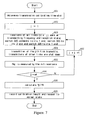
- Figure 3 shows the real-time calibration flowchart for a TDD CDMA mobile communication system.
- the smart antenna array has n antenna units, and the base station is running normally.
- FIG. 4 shows a typical base station with a smart antenna in a FDD CDMA wireless communication system or a wireless loop system.
- the base station includes the following main parts: two antenna arrays: the receiving antenna array 301, which consists of n antenna units 301a, 301b ... 301n, and the transmitting antenna array 302, which consists of m antenna units 311a, 311b ... 311m; there are n receiving feeder cables 302a, 302b ... 302n and m transmitting feeder cables 312a, 312b ... 312m; there are n radio frequency receivers 303a, 303b ... 303n and m radio frequency transmitters 313a, 313b ... 313m; and the baseband processor 304.
- n and m are the number of antenna units for the receiving antenna array and the transmitting antenna array, respectively, and they may be equal or non-equal.
- n receivers 303 and m transmitters 313 (including power amplifiers) in the system. All receivers 303 and transmitters 313 have the same benchmark clock, and the receiving local oscillator 308 and the transmitting local oscillator 309 are locked on the benchmark clock in order to make radio frequency transceivers are coherent.
- the pre-calibration procedure of two-antenna array is same as the TDD system, shown in Figure 2.
- the radio frequency/microwave vector network analyzer measures points A R a, A R b ... A R n and A T a, A T b ... A T m; and after installation, it measures points B R a, B R b ... B R n and B T a, B T b ... B T m.
- the transmission-coefficient matrices of two antenna arrays including the transmission-coefficient matrix of the receiving antenna array C R and the transmission-coefficient matrix of the transmitting antenna array C T , are obtained.
- a coupled circuit 315 is added between each pair of the receiving antenna unit 301 and transmitting antenna unit 311 and between the receiver 303 and transmitter 313. This means that the receiver can measure the signal with transmitting frequency when the transmitting antenna array is calibrated and the transmitter can transmit the signal with receiving frequency when the receiving antenna array is calibrated.
- Figure 5 shows the coupled circuit that is suitable for the number of antenna unit of the receiving antenna array n is not less than the number of antenna unit of the transmitting antenna array m .
- the coupled circuit should have the following functions:
- the receiver of a receiving link is 303x
- the receiving antenna unit is 301x
- the transmitter of a transmitting link is 313j
- the transmitting antenna unit is 311j
- the coupled circuit consists of first, second and third couplers 325, 324 and 322, first, second and third radio frequency switches 326, 323 and 328, and the match resistances 327 and 321.
- the first coupler 325 is connected between the receiving antenna unit 301x and the receiver 303x, and the first coupler 325 is also connected with the end 1 of the first radio frequency switch 326.
- the end 2 of the first radio frequency switch 326 is connected with the match resistance 327, and the radio frequency switch 326 is serially connected with the second radio frequency switch 323.
- the end 1 of the radio frequency switch 323 is connected with the match resistance 321, and the end 2 of the radio frequency switch 323 is connected with the third radio frequency switch 328.
- the end 1 of the third radio frequency switch 328 is connected to the output of the transmitter power amplifier 338 and the transmitting antenna unit 311j, through the second coupler 324; the end 2 of the third radio frequency switch 328 is connected to the output of the transmitter unit 337, through the third coupler 322.
- the base station automatically controls all the radio frequency switches 326, 323 and 328. All the couplers 325, 324 and 322 are the general radio frequency coupled circuit, and the coupling factor is controlled between -20 to -40dB.
- the first radio frequency switch 326 connects to the end 2
- the second radio frequency switch 323 connects to the end 1
- the third radio frequency switch 328 connects to the end 2 to make the system has better isolation between the receiving and transmitting antenna arrays.
- Figures 6 and 7 show the real-time calibration procedure of a smart antenna for the FDD system.
- a smart antenna array with three links (links 1, 2 and 3) as an example to explain the calibration procedures of the receiving antenna array and the transmitting antenna array.
- Figure 6 shows the calibration procedure of the receiving antenna array.
- first link (a) is the reference link (any link can be set as the reference link).
- the coupled circuits of the second and third links are set as follow: the radio frequency switch 326 connects to its end 1; the radio frequency switch 323 connects to its end 2; and shut down all power amplifiers 338.
- the second and third links are set at transmitting states in sequence and work at the received signal frequency; input a unit of transmitted data in baseband, and at the same time open all the receiver; there are n - 1 links, i.e. two links in this case, at receiving states to receive the transmitted data above; and then the followings are obtained:
- Figure 6 shows the calibration procedure as follows, where link 1 in the smart antenna including links 1, 2, and 3 is set as the reference link (any link can be set as the reference link):
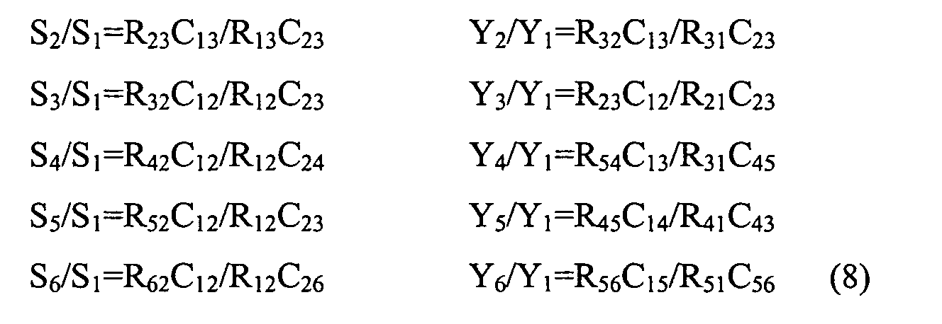
- the calculation formulas are given in the following, when the number of the antenna units of a smart antenna array equals to 3, 4, 6 and 8, respectively, and link 1 is set as the reference link, and S 1 is the reception transmission-coefficient matrix of the reference link.
- Figure 7 shows the calibration procedure of the transmitting antenna array.
- first link (a) is the reference link (any link can be set as the reference link).
- the coupled circuits of all links expect the transmitting link are set as follow: the radio frequency switch 326 connects to its end 1; the radio frequency switch 323 connects to its end 2; the radio frequency switch 328 connects to its end 1.
- every link is set at transmitting states in sequence; input a unit of transmitted data in baseband; and shut down all other links including their transmitters and power amplifiers.
- all receivers are opened and work on the transmission frequency, except the receiver that couples with the transmitting link. Therefore, there are m-1 links at receiving states to receive the transmitted data above; and then the followings are obtained:
- calculation formulas are given in the following, when the number of the antenna units of a smart antenna array equals to 3, 4, 6 and 8, respectively.
- Characteristics of the invention are as follows: the antenna array is pre-calibrated at the vendor to obtain transmission-coefficient matrix between antenna units; the transmission-coefficient matrix is stored in network management equipment of the mobile communication system, and then after installation said transmission-coefficient matrix is loaded into the base station; during operation of the base station, when calibration is expected at any time, a time-slot is determined first, then a transmission link transmits a fixed level signal (data) and other links receive the signal; based on the amplitude and phase of the received signals, the transmission-coefficient matrix and the reception-coefficient matrix of an antenna array, which are relative to the transmission-coefficient matrix of a reference link, can be calculated to perform calibration in real time.
- the real-time calibration method for a smart antenna array not only can be used for TDD mode that has an antenna array for transmission and reception, but also can be used for FDD mode that has separated antenna arrays for transmission and reception, respectively.
- the method does not need any beacon antenna, coupled structure of the antenna array and a special calibration link.
- the above embodiments are for a CDMA wireless communication system, but after simple revision, the method can be used for a FDMA and TDMA wireless communication system.
- Engineers who work on the wireless communication system and know the basic principle of a smart antenna can make the real-time calibration for a smart antenna array after reading this description.
Landscapes
- Engineering & Computer Science (AREA)
- Computer Networks & Wireless Communication (AREA)
- Signal Processing (AREA)
- Physics & Mathematics (AREA)
- Electromagnetism (AREA)
- Radio Transmission System (AREA)
- Mobile Radio Communication Systems (AREA)
- Variable-Direction Aerials And Aerial Arrays (AREA)
Abstract
Description


Step 402, Set the other n - 1 links at the receiving states that receive the unit data sent by the transmitting link;
Step 403, With the radio frequency/microwave vector network analyzer, the received signals of the n - 1 receiving links Rji (j = 1, 2 ... n; and j≠i) are measured one by one;
Step 404, Record the n - 1 measurements of this time;
Step 405, Detect whether i equals to n, when i≠ n go to Step 406 and when i=n go to Step 407;
Step 406, Calculate i=i+1 and determine a time slot, and then execute Steps 401 to 405 again;
Step 407, Calculate each receiving transmission-coefficient ratio of the other links (except the reference link) and the reference link Si/St, and each transmitting transmission-coefficient ratio of the other links (except the reference link) and the reference link Yi/Yt, and then the real-time calibration is ended.
Claims (13)
- A real-time calibration method for a smart antenna array, comprising,A) before installation, pre-calibrating the smart antenna array to obtain a pre-calibration transmission-coefficient matrix between antenna units in the smart antenna array;B) after installation at site, loading the pre-calibration transmission-coefficient matrix into a base station to which the smart antenna array connects;C) during the base station is running, transmitting a unit calibration signal in sequence in a time-slot by every transmitting link of the base station, and at the same time setting all other links of the smart antenna array, except the transmitting link, being in a reception state to receive the unit calibration signal, then measuring and recording the received unit calibration signal;D) with the received unit calibration signal and pre-calibration transmission-coefficient matrix, respectively calculating a ratio of a receiving transmission-coefficient matrix of each receiving link to a receiving transmission-coefficient matrix of a reference link, and respectively calculating a ratio of transmitting transmission-coefficient matrix of each transmitting link to a transmitting transmission-coefficient matrix of the reference link.
- The real-time calibration method for a smart antenna array according to Claim 1, step of pre-calibrating in Step A is performed with a radio frequency/microwave vector network analyzer, of which one end is connected with a transmitting antenna unit interface of the transmitting link and another end is connected with a receiving antenna unit interface of the receiving link; step of measuring the received unit calibration signal in Step C is performed with the radio frequency/microwave vector network analyzer, of which one end is connected with a transmitting antenna system interface of the transmitting link and another end is connected with a receiving antenna system interface of the transmitting link.
- The real-time calibration method for a smart antenna array according to Claim 2, wherein the receiving antenna system interface is an interface between radio frequency transceiver of the receiving link and a digital signal processor, the transmitting antenna system interface is an interface between radio frequency transceiver of the transmitting link and the digital signal processor.
- The real-time calibration method for a smart antenna array according to Claim 1, wherein Step A comprises, measuring coupling characteristics between every antenna unit of the antenna array within a frequency range to obtain pre-calibration transmission-coefficient matrix of every antenna unit of said antenna array.
- The real-time calibration method for a smart antenna array according to Claim 1, wherein Step B comprises, first storing the pre-calibration transmission-coefficient matrix of every antenna unit of the antenna array in a network management equipment of a mobile communication system, and then loading the pre-calibration transmission-coefficient matrix to the base station to which the smart antenna array connects by the network management equipment.
- The real-time calibration method for a smart antenna array according to Claim 1, wherein the smart antenna array has N antenna units, and Step C executes N times taking N time-slots in one frame or different frames, wherein N is a positive integer.
- The real-time calibration method for a smart antenna array according to Claim 1, the time-slot is an idle time-slot.
- The real-time calibration method for a smart antenna array according to Claim 1, the time-slot in step C is a Guard slot (G) between Downlink Pilot Time-Slot (DwPTS) and Uplink Pilot Time-Slot (UpPTS) in the frame for a TD-SCDMA system.
- The real-time calibration method for a smart antenna array according to Claim 1, wherein the smart antenna array is common for every transmission and reception link in a TDD-CDMA mobile communication system.
- The real-time calibration method for a smart antenna array according to Claim 1, for a FDD-CDMA mobile communication system,
wherein Step A comprises, pre-calibrating reception antenna units of a reception antenna array and transmission antenna units of a transmission antenna array, respectively; Step B comprises, loading a pre-calibration transmission-coefficient matrix of the reception antenna array and a pre-calibration transmission-coefficient matrix of the transmission antenna array to the base station;
Step B further comprises,
setting a coupled circuit between each pair of the reception antenna unit and the transmission antenna unit and between each pair of the receiver and the transmitter,
setting the receiver working at the transmitter's transmitting frequency range to receive a transmitted signal from the transmitter through the coupled circuit while calibrating the transmission antenna array, and
setting the transmitter working at the receiver's receiving frequency range to transmit a signal that can be received by the receiver through the coupled circuit while calibrating the reception antenna array;
wherein the step of measuring and recording the received unit calibration signal in Step C comprises,
measuring the unit calibration signal received by reception links of the transmission antenna system, and
measuring the unit calibration signal received by reception links of the reception antenna system. - The real-time calibration method for a smart antenna array according to Claim 10, Step C further comprises:for real-time calibration of the reception antenna system, through control of the coupled circuit, coupling a reception antenna unit of the said transmitting link with the reception antenna unit's paired transmitter; isolating reception antenna units of all other links except the transmitting link from reception antenna units' paired transmitters; and shutting down transmitter power amplifiers of all other links except the transmitting link;for real-time calibration of the transmission antenna system, through control of the coupled circuit, coupling receivers of all the links except the transmitting link with the receivers' paired transmission antenna units; isolating the transmitting link from the transmitting link's paired receiver, and shutting down transmitters and power amplifiers of all the links except the transmitting link.
- The real-time calibration method for a smart antenna array according to Claim 10, step of setting a coupled circuit comprises,
setting the coupled circuit that includes a first, a second and a third coupler, a first, a second and a third radio frequency switch, a first and a second match resistance;
connecting said first coupler between the reception antenna unit and its receiver, and further connecting said first coupler to end 1 of said first radio frequency switch; connecting end 2 of said first radio frequency switch to said first match resistance; and connecting said first radio frequency switch and said second radio frequency switch serially; connecting end 1 of said second radio frequency switch to said second match resistance; connecting end 2 of said second radio frequency switch to said third radio frequency switch; connecting end 1 of said third radio frequency switch to the transmitting antenna unit and output of the power amplifier in the transmitter through second coupler, and connecting end 2 of said third radio frequency switch to output of the transmitter unit in the transmitter through said third coupler;
wherein said first, second and third radio frequency switches are controlled by the base station. - The real-time calibration method for a smart antenna array according to Claim 12, said coupler is a general radio frequency coupler with a coupling factor between -20 dB to -40 dB.
Applications Claiming Priority (3)
| Application Number | Priority Date | Filing Date | Title |
|---|---|---|---|
| CN02131218 | 2002-09-13 | ||
| CNB021312184A CN1170450C (en) | 2002-09-13 | 2002-09-13 | Real-time Calibration Method for Smart Antenna Array |
| PCT/CN2003/000779 WO2004025872A1 (en) | 2002-09-13 | 2003-09-15 | Method for calibrating smart antenna array in real time |
Publications (3)
| Publication Number | Publication Date |
|---|---|
| EP1548957A1 true EP1548957A1 (en) | 2005-06-29 |
| EP1548957A4 EP1548957A4 (en) | 2011-10-26 |
| EP1548957B1 EP1548957B1 (en) | 2016-07-20 |
Family
ID=27811325
Family Applications (1)
| Application Number | Title | Priority Date | Filing Date |
|---|---|---|---|
| EP03750242.4A Expired - Lifetime EP1548957B1 (en) | 2002-09-13 | 2003-09-15 | Method for calibrating smart antenna array in real time |
Country Status (7)
| Country | Link |
|---|---|
| US (1) | US7098847B2 (en) |
| EP (1) | EP1548957B1 (en) |
| JP (1) | JP4092335B2 (en) |
| KR (1) | KR100655767B1 (en) |
| CN (1) | CN1170450C (en) |
| AU (1) | AU2003271014A1 (en) |
| WO (1) | WO2004025872A1 (en) |
Cited By (5)
| Publication number | Priority date | Publication date | Assignee | Title |
|---|---|---|---|---|
| EP1585231A4 (en) * | 2002-12-25 | 2006-12-06 | Da Tang Mobile Comm Equipment | A method for calibrating smart antenna array systems in real time |
| EP1770827A1 (en) * | 2005-09-28 | 2007-04-04 | Alcatel Lucent | Calibration method for smart antenna arrays |
| CN101359012B (en) * | 2007-07-31 | 2010-12-08 | 大唐移动通信设备有限公司 | Method for measuring antenna performance |
| CN105790812B (en) * | 2016-04-29 | 2018-08-31 | 中国人民解放军国防科学技术大学 | It is a kind of to receive system and method using the ground station signals enhancing of spaced antenna battle array |
| US20180254839A1 (en) * | 2017-03-06 | 2018-09-06 | Samsung Electronics Co., Ltd | Methods and apparatus for calibration and array operation in advanced mimo system |
Families Citing this family (50)
| Publication number | Priority date | Publication date | Assignee | Title |
|---|---|---|---|---|
| US7486740B2 (en) * | 2004-04-02 | 2009-02-03 | Qualcomm Incorporated | Calibration of transmit and receive chains in a MIMO communication system |
| US20060280655A1 (en) * | 2005-06-08 | 2006-12-14 | California Institute Of Technology | Intravascular diagnostic and therapeutic sampling device |
| CN101064902B (en) * | 2006-04-25 | 2010-11-10 | 大唐移动通信设备有限公司 | Method for real-time calibrating intelligent antenna |
| JP3930037B1 (en) * | 2006-04-27 | 2007-06-13 | 株式会社アドバンテスト | Test apparatus and test method |
| KR101009781B1 (en) * | 2006-07-11 | 2011-01-19 | 삼성전자주식회사 | Calibration device and method in communication system |
| US7576686B2 (en) * | 2006-08-07 | 2009-08-18 | Garmin International, Inc. | Method and system for calibrating an antenna array for an aircraft surveillance system |
| WO2008053342A2 (en) * | 2006-11-02 | 2008-05-08 | Nokia Corporation | Alternative time division duplex frame structure optimization |
| CN101188448B (en) * | 2006-11-15 | 2011-09-14 | 电信科学技术研究院 | A smart antenna calibration method, device and system |
| US8049662B2 (en) * | 2007-07-23 | 2011-11-01 | Aviation Communication&Surveillance Systems LLC | Systems and methods for antenna calibration |
| CN101674140A (en) * | 2008-09-08 | 2010-03-17 | 大唐移动通信设备有限公司 | Method and device for calibrating antennae |
| CN101714879B (en) * | 2008-10-08 | 2013-03-20 | 扬智科技股份有限公司 | Smart Antenna Full-Frequency Scanning and Method for Adjusting Channel Parameters |
| US8193971B2 (en) * | 2008-11-10 | 2012-06-05 | Motorola Mobility, Inc. | Antenna reciprocity calibration |
| CN101425833B (en) * | 2008-12-09 | 2013-03-13 | 成都福兰特电子技术有限公司 | Base station signal optimization system and method thereof |
| US8219035B2 (en) * | 2009-09-18 | 2012-07-10 | ReVerb Networks, Inc. | Enhanced calibration for multiple signal processing paths in a wireless network |
| US8179314B2 (en) * | 2009-10-22 | 2012-05-15 | ReVerb Networks, Inc. | Enhanced calibration for multiple signal processing paths in a frequency division duplex system |
| KR101285388B1 (en) * | 2009-12-18 | 2013-07-10 | 한국전자통신연구원 | Beam steering apparatus |
| CN102244531B (en) * | 2010-05-14 | 2014-08-13 | 电信科学技术研究院 | Method and device for dynamically adjusting antenna calibration position |
| CN103546205B (en) * | 2010-05-14 | 2016-04-20 | 电信科学技术研究院 | A kind of method of antenna calibration position dynamic conditioning and device |
| CN102299730B (en) * | 2010-06-22 | 2015-09-16 | 中兴通讯股份有限公司 | A kind of antenna correcting method based on TDD coordinated multipoint transmission and system |
| JP5104938B2 (en) * | 2010-12-09 | 2012-12-19 | 株式会社デンソー | Phased array antenna phase calibration method and phased array antenna |
| US8452246B2 (en) * | 2011-04-07 | 2013-05-28 | Intel Mobile Communications GmbH | Antenna tuner in combination with modified feedback receiver for improved antenna matching |
| CN102149123B (en) * | 2011-04-15 | 2013-12-04 | 北京邮电大学 | Scheme and device for calibrating antennae among base stations in cooperative multi-point system and base station |
| CN102843173B (en) * | 2011-06-21 | 2016-08-24 | 中兴通讯股份有限公司 | Antenna calibration method in a kind of time division duplex Synergistic multi-point system and device |
| CN103107836B (en) * | 2011-11-10 | 2015-12-09 | 中国移动通信集团公司 | A kind of antenna calibration method and device |
| CN103916168B (en) * | 2013-01-04 | 2018-02-23 | 中国移动通信集团公司 | A kind of antenna calibration method and device |
| KR101994325B1 (en) * | 2013-05-31 | 2019-09-30 | 삼성전자주식회사 | Array antenna apparatus and control method thereof in communication system |
| CN104243055B (en) * | 2013-06-20 | 2016-06-29 | 华为技术有限公司 | The method of multi-antenna channel correction, device and base station system |
| CN103795483B (en) * | 2014-01-29 | 2016-08-17 | 浙江网新技术有限公司 | antenna transmission performance adjusting method |
| US10056685B2 (en) | 2014-03-06 | 2018-08-21 | Samsung Electronics Co., Ltd. | Antenna array self-calibration |
| CN105812073A (en) * | 2014-12-31 | 2016-07-27 | 上海贝尔股份有限公司 | Horizontal and vertical combined calibration method and device for active antenna array |
| CN106033984B (en) * | 2015-03-11 | 2020-12-18 | 中兴通讯股份有限公司 | Method and system for calibrating downlink and uplink channel of smart antenna |
| US9759799B2 (en) * | 2015-06-24 | 2017-09-12 | International Business Machines Corporation | Beacon array |
| US9872136B2 (en) * | 2015-06-29 | 2018-01-16 | Intel IP Corporation | Method and apparatus for transmitter geo-location in mobile platforms |
| US20170045603A1 (en) * | 2015-08-14 | 2017-02-16 | Tektronix, Inc. | Synchronization of unstable signal sources for use in a phase stable instrument |
| CN105846917A (en) * | 2016-03-16 | 2016-08-10 | 太仓市同维电子有限公司 | Calibration system and calibration method thereof based on wireless test |
| EP3465950B1 (en) | 2016-05-26 | 2020-07-15 | Telefonaktiebolaget LM Ericsson (Publ) | Method of calibrating an antenna system |
| EP3293897B8 (en) | 2016-09-12 | 2020-08-12 | Rohde & Schwarz GmbH & Co. KG | System and method for characterization of multi-element antenna |
| CN106934097B (en) * | 2017-02-09 | 2020-03-17 | 西安电子科技大学 | Electrical performance-oriented key dynamic mode selection method for spatial mesh antenna |
| PL3596780T3 (en) | 2017-03-13 | 2022-01-31 | Telefonaktiebolaget Lm Ericsson (Publ) | Self-calibration of antenna array system |
| US11469498B2 (en) | 2017-09-15 | 2022-10-11 | Telefonaktiebolaget Lm Ericsson (Publ) | Systems and methods for self-calibration of an analog beamforming transceiver |
| WO2019078766A1 (en) * | 2017-10-20 | 2019-04-25 | Telefonaktiebolaget Lm Ericsson (Publ) | Over-the-air reciprocity calibration for distributed – multiple input - multiple output systems |
| CN108400785A (en) * | 2018-02-10 | 2018-08-14 | 广东圣大电子有限公司 | A kind of miniaturization microwave broadband victory frequency Up/Down Conversion system and calibration method |
| JP6992589B2 (en) * | 2018-02-23 | 2022-01-13 | 沖電気工業株式会社 | Phase adjuster and wireless device |
| CN110311701B (en) * | 2018-03-23 | 2022-03-01 | 中兴通讯股份有限公司 | Transceiver, receiving channel and transmitting channel calibration method and device |
| CN110579648A (en) * | 2018-06-11 | 2019-12-17 | 杭州涂鸦信息技术有限公司 | antenna gain judging method and judging device |
| CN112311481B (en) * | 2019-08-02 | 2023-09-15 | 中兴通讯股份有限公司 | An antenna correction method, base station and storage medium |
| CN111490835B (en) * | 2020-03-05 | 2022-08-26 | 西安宇飞电子技术有限公司 | Self-calibration method, device and equipment for narrow-band signal |
| CN112635992B (en) * | 2020-12-08 | 2021-12-07 | 四川天邑康和通信股份有限公司 | 5G ultra-wideband dual-polarized coupled radiation antenna |
| WO2022252074A1 (en) * | 2021-05-31 | 2022-12-08 | 北京小米移动软件有限公司 | Control method and apparatus for radio frequency circuit |
| CN116165411B (en) * | 2021-11-24 | 2025-07-18 | 中国信息通信研究院 | Electric field probe calibration method, device and system |
Family Cites Families (8)
| Publication number | Priority date | Publication date | Assignee | Title |
|---|---|---|---|---|
| US6124824A (en) * | 1999-01-29 | 2000-09-26 | Cwill Telecommunications, Inc. | Adaptive antenna array system calibration |
| CN1118146C (en) | 1999-08-10 | 2003-08-13 | 信息产业部电信科学技术研究院 | Method and device for calibrating intelligent antenna array |
| US6236839B1 (en) * | 1999-09-10 | 2001-05-22 | Utstarcom, Inc. | Method and apparatus for calibrating a smart antenna array |
| SE522563C2 (en) * | 2000-02-01 | 2004-02-17 | Ericsson Telefon Ab L M | Calibration method for an adaptive group antenna |
| KR100913883B1 (en) * | 2002-04-19 | 2009-08-26 | 삼성전자주식회사 | Output signal distortion measurement and compensation device and method of smart antenna |
| KR100608736B1 (en) * | 2003-04-29 | 2006-08-04 | 엘지전자 주식회사 | Reference signal generator of smart antenna system |
| ATE487291T1 (en) * | 2003-08-27 | 2010-11-15 | Wavion Ltd | WIFI CAPACITY EXPANSION BY USING SDM |
| US7486740B2 (en) * | 2004-04-02 | 2009-02-03 | Qualcomm Incorporated | Calibration of transmit and receive chains in a MIMO communication system |
-
2002
- 2002-09-13 CN CNB021312184A patent/CN1170450C/en not_active Expired - Lifetime
-
2003
- 2003-09-15 AU AU2003271014A patent/AU2003271014A1/en not_active Abandoned
- 2003-09-15 JP JP2004534949A patent/JP4092335B2/en not_active Expired - Lifetime
- 2003-09-15 EP EP03750242.4A patent/EP1548957B1/en not_active Expired - Lifetime
- 2003-09-15 KR KR1020057004285A patent/KR100655767B1/en not_active Expired - Lifetime
- 2003-09-15 WO PCT/CN2003/000779 patent/WO2004025872A1/en not_active Ceased
-
2005
- 2005-03-11 US US11/078,906 patent/US7098847B2/en not_active Expired - Lifetime
Cited By (7)
| Publication number | Priority date | Publication date | Assignee | Title |
|---|---|---|---|---|
| EP1585231A4 (en) * | 2002-12-25 | 2006-12-06 | Da Tang Mobile Comm Equipment | A method for calibrating smart antenna array systems in real time |
| EP1770827A1 (en) * | 2005-09-28 | 2007-04-04 | Alcatel Lucent | Calibration method for smart antenna arrays |
| US7593826B2 (en) | 2005-09-28 | 2009-09-22 | Alcatel | Calibration method for smart antenna arrays |
| CN101359012B (en) * | 2007-07-31 | 2010-12-08 | 大唐移动通信设备有限公司 | Method for measuring antenna performance |
| CN105790812B (en) * | 2016-04-29 | 2018-08-31 | 中国人民解放军国防科学技术大学 | It is a kind of to receive system and method using the ground station signals enhancing of spaced antenna battle array |
| US20180254839A1 (en) * | 2017-03-06 | 2018-09-06 | Samsung Electronics Co., Ltd | Methods and apparatus for calibration and array operation in advanced mimo system |
| US10523345B2 (en) * | 2017-03-06 | 2019-12-31 | Samsung Electronics Co., Ltd. | Methods and apparatus for calibration and array operation in advanced MIMO system |
Also Published As
| Publication number | Publication date |
|---|---|
| KR100655767B1 (en) | 2006-12-11 |
| EP1548957B1 (en) | 2016-07-20 |
| AU2003271014A1 (en) | 2004-04-30 |
| EP1548957A4 (en) | 2011-10-26 |
| CN1170450C (en) | 2004-10-06 |
| KR20050042817A (en) | 2005-05-10 |
| US20050239506A1 (en) | 2005-10-27 |
| WO2004025872A1 (en) | 2004-03-25 |
| US7098847B2 (en) | 2006-08-29 |
| CN1446006A (en) | 2003-10-01 |
| JP2005538621A (en) | 2005-12-15 |
| JP4092335B2 (en) | 2008-05-28 |
Similar Documents
| Publication | Publication Date | Title |
|---|---|---|
| EP1548957B1 (en) | Method for calibrating smart antenna array in real time | |
| RU2265263C2 (en) | Method and device for calibrating intelligent antenna array | |
| AU689933B2 (en) | Antenna and feeder cable tester | |
| WO2008074925A1 (en) | Communication method and system | |
| KR19980069840A (en) | Voltage standing wave ratio measuring device of base station antenna and its method | |
| CN101180551A (en) | Antenna array calibration | |
| KR19980075435A (en) | Standing Wave Ratio Measurement Method of Mobile Communication System | |
| US12074648B2 (en) | In-device characterization of antenna coupling | |
| JP2022517916A (en) | Power adjustment method and device, array antenna, storage medium | |
| CN1753329A (en) | Method of timing and timing calibration of base station radio frequency remoter and its use | |
| CN112698113A (en) | Amplitude calibration method and device of receiving channel and network equipment | |
| KR100531619B1 (en) | Apparatus and method of receiving sensitivity measuring for communication system with receiving only path | |
| KR20100068821A (en) | Apparatus for measuring voltage standing wave ratio in wireless lan | |
| CN218603490U (en) | Device supporting large-scale MIMO transceiver phase calibration function | |
| CN112615681B (en) | Amplitude calibration method and device of transmitting channel and network equipment | |
| CN101227211B (en) | Method and apparatus for calibration of power of receiving main broadband | |
| US20050181784A1 (en) | System and method for calibrating a transceiver | |
| CN102113251A (en) | Method of and equalizer for equalizing a radio frequency filter | |
| CN112615687A (en) | Phase calibration method and device of receiving channel and network equipment | |
| JP2928167B2 (en) | Cellular phone and its antenna performance test method | |
| KR100626207B1 (en) | Cable calibration method using a self-transmitting device and a recording medium storing the device and a program including the method | |
| KR101897107B1 (en) | Wireless transmitting/receiving device and method thereof | |
| WO2005099212A1 (en) | Gain measurement device for on line calibration and thereof method | |
| WO2002060197A1 (en) | Method and system for selecting an optimal antenna location in a telecommunication system | |
| KR20060078307A (en) | Mobile communication terminal that can control the transmission power of wireless signal output to base station by measuring reflected wireless signal level |
Legal Events
| Date | Code | Title | Description |
|---|---|---|---|
| PUAI | Public reference made under article 153(3) epc to a published international application that has entered the european phase |
Free format text: ORIGINAL CODE: 0009012 |
|
| 17P | Request for examination filed |
Effective date: 20050413 |
|
| AK | Designated contracting states |
Kind code of ref document: A1 Designated state(s): AT BE BG CH CY CZ DE DK EE ES FI FR GB GR HU IE IT LI LU MC NL PT RO SE SI SK TR |
|
| AX | Request for extension of the european patent |
Extension state: AL LT LV MK |
|
| DAX | Request for extension of the european patent (deleted) | ||
| RAP1 | Party data changed (applicant data changed or rights of an application transferred) |
Owner name: CHINA ACADEMY OF TELECOMMUNICATIONS TECHNOLOGY |
|
| A4 | Supplementary search report drawn up and despatched |
Effective date: 20110922 |
|
| RIC1 | Information provided on ipc code assigned before grant |
Ipc: H01Q 3/26 20060101ALI20110916BHEP Ipc: H04B 17/00 20060101AFI20110916BHEP |
|
| 17Q | First examination report despatched |
Effective date: 20121001 |
|
| REG | Reference to a national code |
Ref country code: DE Ref legal event code: R079 Ref document number: 60349165 Country of ref document: DE Free format text: PREVIOUS MAIN CLASS: H04B0007020000 Ipc: H04B0017120000 |
|
| GRAP | Despatch of communication of intention to grant a patent |
Free format text: ORIGINAL CODE: EPIDOSNIGR1 |
|
| RIC1 | Information provided on ipc code assigned before grant |
Ipc: H04B 17/21 20150101ALI20160119BHEP Ipc: H04B 17/12 20150101AFI20160119BHEP Ipc: H01Q 3/26 20060101ALI20160119BHEP Ipc: H04B 17/19 20150101ALI20160119BHEP Ipc: H04B 17/18 20150101ALI20160119BHEP |
|
| INTG | Intention to grant announced |
Effective date: 20160203 |
|
| GRAS | Grant fee paid |
Free format text: ORIGINAL CODE: EPIDOSNIGR3 |
|
| GRAA | (expected) grant |
Free format text: ORIGINAL CODE: 0009210 |
|
| AK | Designated contracting states |
Kind code of ref document: B1 Designated state(s): AT BE BG CH CY CZ DE DK EE ES FI FR GB GR HU IE IT LI LU MC NL PT RO SE SI SK TR |
|
| REG | Reference to a national code |
Ref country code: GB Ref legal event code: FG4D |
|
| REG | Reference to a national code |
Ref country code: DE Ref legal event code: R081 Ref document number: 60349165 Country of ref document: DE Owner name: DATANG MOBILE COMMUNICATIONS EQUIPMENT CO., LT, CN Free format text: FORMER OWNER: DA TANG MOBILE COMMUNICATIONS EQUIPMENT CO., LTD., PEKING/BEI-JING, CN |
|
| REG | Reference to a national code |
Ref country code: CH Ref legal event code: EP |
|
| REG | Reference to a national code |
Ref country code: IE Ref legal event code: FG4D |
|
| REG | Reference to a national code |
Ref country code: AT Ref legal event code: REF Ref document number: 814828 Country of ref document: AT Kind code of ref document: T Effective date: 20160815 |
|
| REG | Reference to a national code |
Ref country code: DE Ref legal event code: R096 Ref document number: 60349165 Country of ref document: DE |
|
| REG | Reference to a national code |
Ref country code: FR Ref legal event code: PLFP Year of fee payment: 14 |
|
| REG | Reference to a national code |
Ref country code: NL Ref legal event code: MP Effective date: 20160720 |
|
| REG | Reference to a national code |
Ref country code: AT Ref legal event code: MK05 Ref document number: 814828 Country of ref document: AT Kind code of ref document: T Effective date: 20160720 |
|
| PG25 | Lapsed in a contracting state [announced via postgrant information from national office to epo] |
Ref country code: FI Free format text: LAPSE BECAUSE OF FAILURE TO SUBMIT A TRANSLATION OF THE DESCRIPTION OR TO PAY THE FEE WITHIN THE PRESCRIBED TIME-LIMIT Effective date: 20160720 Ref country code: NL Free format text: LAPSE BECAUSE OF FAILURE TO SUBMIT A TRANSLATION OF THE DESCRIPTION OR TO PAY THE FEE WITHIN THE PRESCRIBED TIME-LIMIT Effective date: 20160720 Ref country code: IT Free format text: LAPSE BECAUSE OF FAILURE TO SUBMIT A TRANSLATION OF THE DESCRIPTION OR TO PAY THE FEE WITHIN THE PRESCRIBED TIME-LIMIT Effective date: 20160720 |
|
| PG25 | Lapsed in a contracting state [announced via postgrant information from national office to epo] |
Ref country code: SE Free format text: LAPSE BECAUSE OF FAILURE TO SUBMIT A TRANSLATION OF THE DESCRIPTION OR TO PAY THE FEE WITHIN THE PRESCRIBED TIME-LIMIT Effective date: 20160720 Ref country code: PT Free format text: LAPSE BECAUSE OF FAILURE TO SUBMIT A TRANSLATION OF THE DESCRIPTION OR TO PAY THE FEE WITHIN THE PRESCRIBED TIME-LIMIT Effective date: 20161121 Ref country code: GR Free format text: LAPSE BECAUSE OF FAILURE TO SUBMIT A TRANSLATION OF THE DESCRIPTION OR TO PAY THE FEE WITHIN THE PRESCRIBED TIME-LIMIT Effective date: 20161021 Ref country code: ES Free format text: LAPSE BECAUSE OF FAILURE TO SUBMIT A TRANSLATION OF THE DESCRIPTION OR TO PAY THE FEE WITHIN THE PRESCRIBED TIME-LIMIT Effective date: 20160720 Ref country code: AT Free format text: LAPSE BECAUSE OF FAILURE TO SUBMIT A TRANSLATION OF THE DESCRIPTION OR TO PAY THE FEE WITHIN THE PRESCRIBED TIME-LIMIT Effective date: 20160720 |
|
| REG | Reference to a national code |
Ref country code: DE Ref legal event code: R097 Ref document number: 60349165 Country of ref document: DE |
|
| PG25 | Lapsed in a contracting state [announced via postgrant information from national office to epo] |
Ref country code: EE Free format text: LAPSE BECAUSE OF FAILURE TO SUBMIT A TRANSLATION OF THE DESCRIPTION OR TO PAY THE FEE WITHIN THE PRESCRIBED TIME-LIMIT Effective date: 20160720 Ref country code: RO Free format text: LAPSE BECAUSE OF FAILURE TO SUBMIT A TRANSLATION OF THE DESCRIPTION OR TO PAY THE FEE WITHIN THE PRESCRIBED TIME-LIMIT Effective date: 20160720 Ref country code: MC Free format text: LAPSE BECAUSE OF FAILURE TO SUBMIT A TRANSLATION OF THE DESCRIPTION OR TO PAY THE FEE WITHIN THE PRESCRIBED TIME-LIMIT Effective date: 20160720 |
|
| REG | Reference to a national code |
Ref country code: CH Ref legal event code: PL |
|
| PLBE | No opposition filed within time limit |
Free format text: ORIGINAL CODE: 0009261 |
|
| STAA | Information on the status of an ep patent application or granted ep patent |
Free format text: STATUS: NO OPPOSITION FILED WITHIN TIME LIMIT |
|
| PG25 | Lapsed in a contracting state [announced via postgrant information from national office to epo] |
Ref country code: SK Free format text: LAPSE BECAUSE OF FAILURE TO SUBMIT A TRANSLATION OF THE DESCRIPTION OR TO PAY THE FEE WITHIN THE PRESCRIBED TIME-LIMIT Effective date: 20160720 Ref country code: DK Free format text: LAPSE BECAUSE OF FAILURE TO SUBMIT A TRANSLATION OF THE DESCRIPTION OR TO PAY THE FEE WITHIN THE PRESCRIBED TIME-LIMIT Effective date: 20160720 Ref country code: BG Free format text: LAPSE BECAUSE OF FAILURE TO SUBMIT A TRANSLATION OF THE DESCRIPTION OR TO PAY THE FEE WITHIN THE PRESCRIBED TIME-LIMIT Effective date: 20161020 Ref country code: CZ Free format text: LAPSE BECAUSE OF FAILURE TO SUBMIT A TRANSLATION OF THE DESCRIPTION OR TO PAY THE FEE WITHIN THE PRESCRIBED TIME-LIMIT Effective date: 20160720 |
|
| 26N | No opposition filed |
Effective date: 20170421 |
|
| REG | Reference to a national code |
Ref country code: IE Ref legal event code: MM4A |
|
| PG25 | Lapsed in a contracting state [announced via postgrant information from national office to epo] |
Ref country code: LI Free format text: LAPSE BECAUSE OF NON-PAYMENT OF DUE FEES Effective date: 20160930 Ref country code: CH Free format text: LAPSE BECAUSE OF NON-PAYMENT OF DUE FEES Effective date: 20160930 Ref country code: IE Free format text: LAPSE BECAUSE OF NON-PAYMENT OF DUE FEES Effective date: 20160915 |
|
| PG25 | Lapsed in a contracting state [announced via postgrant information from national office to epo] |
Ref country code: SI Free format text: LAPSE BECAUSE OF FAILURE TO SUBMIT A TRANSLATION OF THE DESCRIPTION OR TO PAY THE FEE WITHIN THE PRESCRIBED TIME-LIMIT Effective date: 20160720 Ref country code: LU Free format text: LAPSE BECAUSE OF NON-PAYMENT OF DUE FEES Effective date: 20160915 |
|
| REG | Reference to a national code |
Ref country code: FR Ref legal event code: PLFP Year of fee payment: 15 |
|
| PG25 | Lapsed in a contracting state [announced via postgrant information from national office to epo] |
Ref country code: CY Free format text: LAPSE BECAUSE OF FAILURE TO SUBMIT A TRANSLATION OF THE DESCRIPTION OR TO PAY THE FEE WITHIN THE PRESCRIBED TIME-LIMIT Effective date: 20160720 Ref country code: HU Free format text: LAPSE BECAUSE OF FAILURE TO SUBMIT A TRANSLATION OF THE DESCRIPTION OR TO PAY THE FEE WITHIN THE PRESCRIBED TIME-LIMIT; INVALID AB INITIO Effective date: 20030915 |
|
| PG25 | Lapsed in a contracting state [announced via postgrant information from national office to epo] |
Ref country code: TR Free format text: LAPSE BECAUSE OF FAILURE TO SUBMIT A TRANSLATION OF THE DESCRIPTION OR TO PAY THE FEE WITHIN THE PRESCRIBED TIME-LIMIT Effective date: 20160720 |
|
| REG | Reference to a national code |
Ref country code: FR Ref legal event code: PLFP Year of fee payment: 16 |
|
| REG | Reference to a national code |
Ref country code: DE Ref legal event code: R081 Ref document number: 60349165 Country of ref document: DE Owner name: DATANG MOBILE COMMUNICATIONS EQUIPMENT CO., LT, CN Free format text: FORMER OWNER: CHINA ACADEMY OF TELECOMMUNICATIONS TECHNOLOGY, BEIJING, CN |
|
| REG | Reference to a national code |
Ref country code: BE Ref legal event code: PD Owner name: DATANG MOBILE COMMUNICATIONS EQUIPMENT CO., LTD.; CN Free format text: DETAILS ASSIGNMENT: CHANGE OF OWNER(S), ASSIGNMENT; FORMER OWNER NAME: CHINA ACADEMY OF TELECOMMUNICATIONS TECHNOLOGY Effective date: 20210624 |
|
| REG | Reference to a national code |
Ref country code: GB Ref legal event code: 732E Free format text: REGISTERED BETWEEN 20210729 AND 20210804 |
|
| PGFP | Annual fee paid to national office [announced via postgrant information from national office to epo] |
Ref country code: GB Payment date: 20220920 Year of fee payment: 20 Ref country code: DE Payment date: 20220920 Year of fee payment: 20 |
|
| PGFP | Annual fee paid to national office [announced via postgrant information from national office to epo] |
Ref country code: FR Payment date: 20220922 Year of fee payment: 20 Ref country code: BE Payment date: 20220920 Year of fee payment: 20 |
|
| REG | Reference to a national code |
Ref country code: DE Ref legal event code: R071 Ref document number: 60349165 Country of ref document: DE |
|
| REG | Reference to a national code |
Ref country code: BE Ref legal event code: MK Effective date: 20230915 |
|
| REG | Reference to a national code |
Ref country code: GB Ref legal event code: PE20 Expiry date: 20230914 |
|
| PG25 | Lapsed in a contracting state [announced via postgrant information from national office to epo] |
Ref country code: GB Free format text: LAPSE BECAUSE OF EXPIRATION OF PROTECTION Effective date: 20230914 |