EP1548920A1 - Reduced-consumption dynamic magnetic motor - Google Patents
Reduced-consumption dynamic magnetic motor Download PDFInfo
- Publication number
- EP1548920A1 EP1548920A1 EP03766415A EP03766415A EP1548920A1 EP 1548920 A1 EP1548920 A1 EP 1548920A1 EP 03766415 A EP03766415 A EP 03766415A EP 03766415 A EP03766415 A EP 03766415A EP 1548920 A1 EP1548920 A1 EP 1548920A1
- Authority
- EP
- European Patent Office
- Prior art keywords
- rotor
- dynamic magnetic
- magnetic motor
- cup
- consumption dynamic
- Prior art date
- Legal status (The legal status is an assumption and is not a legal conclusion. Google has not performed a legal analysis and makes no representation as to the accuracy of the status listed.)
- Withdrawn
Links
- 238000004804 winding Methods 0.000 claims description 9
- 238000009987 spinning Methods 0.000 claims description 8
- XEEYBQQBJWHFJM-UHFFFAOYSA-N Iron Chemical compound [Fe] XEEYBQQBJWHFJM-UHFFFAOYSA-N 0.000 claims description 7
- 230000005672 electromagnetic field Effects 0.000 claims description 6
- 239000000463 material Substances 0.000 claims description 5
- 229910000831 Steel Inorganic materials 0.000 claims description 3
- 229910052742 iron Inorganic materials 0.000 claims description 3
- 239000010959 steel Substances 0.000 claims description 3
- 238000010348 incorporation Methods 0.000 claims 1
- 230000001681 protective effect Effects 0.000 claims 1
- 238000011084 recovery Methods 0.000 claims 1
- 230000002093 peripheral effect Effects 0.000 abstract 1
- 230000008846 dynamic interplay Effects 0.000 description 5
- 230000000694 effects Effects 0.000 description 2
- 238000013459 approach Methods 0.000 description 1
- 230000000295 complement effect Effects 0.000 description 1
- 238000001816 cooling Methods 0.000 description 1
- 238000010586 diagram Methods 0.000 description 1
- 230000005674 electromagnetic induction Effects 0.000 description 1
- 238000005265 energy consumption Methods 0.000 description 1
- 238000004519 manufacturing process Methods 0.000 description 1
- 239000002184 metal Substances 0.000 description 1
- 229910052751 metal Inorganic materials 0.000 description 1
Images
Classifications
-
- H—ELECTRICITY
- H02—GENERATION; CONVERSION OR DISTRIBUTION OF ELECTRIC POWER
- H02N—ELECTRIC MACHINES NOT OTHERWISE PROVIDED FOR
- H02N15/00—Holding or levitation devices using magnetic attraction or repulsion, not otherwise provided for
-
- G—PHYSICS
- G09—EDUCATION; CRYPTOGRAPHY; DISPLAY; ADVERTISING; SEALS
- G09F—DISPLAYING; ADVERTISING; SIGNS; LABELS OR NAME-PLATES; SEALS
- G09F19/00—Advertising or display means not otherwise provided for
- G09F19/02—Advertising or display means not otherwise provided for incorporating moving display members
-
- H—ELECTRICITY
- H02—GENERATION; CONVERSION OR DISTRIBUTION OF ELECTRIC POWER
- H02K—DYNAMO-ELECTRIC MACHINES
- H02K99/00—Subject matter not provided for in other groups of this subclass
- H02K99/20—Motors
-
- H—ELECTRICITY
- H02—GENERATION; CONVERSION OR DISTRIBUTION OF ELECTRIC POWER
- H02K—DYNAMO-ELECTRIC MACHINES
- H02K11/00—Structural association of dynamo-electric machines with electric components or with devices for shielding, monitoring or protection
-
- H—ELECTRICITY
- H02—GENERATION; CONVERSION OR DISTRIBUTION OF ELECTRIC POWER
- H02K—DYNAMO-ELECTRIC MACHINES
- H02K7/00—Arrangements for handling mechanical energy structurally associated with dynamo-electric machines, e.g. structural association with mechanical driving motors or auxiliary dynamo-electric machines
- H02K7/08—Structural association with bearings
- H02K7/09—Structural association with bearings with magnetic bearings
Definitions
- the present specification refers to a utility model application relating to a direct current and brushless reduced consumption dynamic magnetic motor, with a motor with variable support, which is based on the application of the Dynamic Interaction Theory, together with electromagnetic induction.
- the invention constituting the motor has as an essential feature having reduced consumption and having very few constructive elements, having an electromagnet provided with an automatic pulse actuation device, such that the metal disc will also be pulse actuated, resulting in obtaining a very low consumption.
- This invention is applicable within the industry dedicated to the manufacture of dynamic magnetic motors.
- the reduced consumption dynamic magnetic motor object of the invention is constituted of a defined surface manufactured in a plastic material, not being completely horizontal, since it will have a shape approximating a cone frustum or cup, incorporating a slight central bulge.
- This surface is defined by a perimetral rim for the purpose of demarcating the movement area of the rotor, also having a spinning top shaped rotor provided with a disc or flywheel in its central magnetized iron portion located transversally to the axis of revolution, the rest of the rotor will be manufactured in plastic material, and the rotor will rotate about its main shaft perpendicularly to the surface of the cup.
- a coil with two winding turns around a core manufactured from a steel pipe has been arranged in the lower portion of the cup, and there is a transistor and direct current power source in the circuit, which could be a common battery for power supply for low amperage motors.
- the magnet will generate an electromagnetic field in the circuit of the coil, which will amplify the magnetic field created by the spinning top.
- the battery or any other direct current source, will maintain the electromagnetic field generated by the coil, which will repel the magnetized disc of the rotor, generating a kinetic energy power supply in this rotor due to the effect of the resulting dynamic interaction according to the Dynamic Interaction Theory.
- the coil thus supplies electromagnetic energy coming from the electrical power source which the rotor converts into kinetic energy with which losses due to friction can be overcome and its rotating speed increased.
- the electromagnet of the coil will generate a magnetic torque that will act on the poles of the magnetized disc of the rotor, generating a dynamic interaction torque perpendicular to the previous one, which will maintain the rotor dynamics.
- the transistor acts as a simple switch such that when the spinning top stops, the motor shuts off and the power supply is cut off with the subsequent savings.
- the motor shuts off and starts up according to whether the spinning top exits or enters the small electromagnetic field generated by the coil and which is located at the center of the base.
- the low consumption dynamic magnetic motor (1) is made up of a circular body (2) adopting a configuration approximating a cone frustum, provided with a slight central bulge and provided with a perimetral rim (5) in the upper portion for the purpose of preventing a spinning top (3), manufactured in plastic material and provided with a magnet (4) and located in its inner area, from leaving to the outside, having a battery (6) in the inner portion and a coil (7) with two winding turns around a steel pipe core.
- a transistor (13) acting as a switch has been provided in the circuit.
- the rotor can be mobilized with a conventional electric motor, with a mechanical arm for starting it up again in the event of an accidental shut off, and this dynamic motor can be provided with blades around its main shaft for the purpose of allowing its actuation as a fan or cooling system.
- the invention has low voltage power supply (10), as shown in Figure 3, the power supply being direct current and a conventional battery would be enough for low amperage motors.
- the magnet (4) When the rotor (3) is in motion rotating on its main shaft, the magnet (4) generates an electromagnetic field in the circuit (11) of the coil (7), which will amplify the magnetic field created by the rotor (3).
- the battery or any direct current power source, will maintain the electromagnetic field generated by the coil (7), which will repel the magnetized disc (4) of the rotor (3), generating a kinetic energy power supply in this rotor.
- the coil (7) thus supplies electromagnetic energy coming from the electrical power supply source (10) which the rotor converts into kinetic energy with which it can overcome losses due to friction and increase its rotating speed.
- the electromagnet of the coil (7) will generate a magnetic torque which will act on the poles of the magnetized disc of the rotor, generating a dynamic interaction torque perpendicular to the previous one, which will maintain the rotor dynamics.
- the transistor (13) acts as a simple switch such that when the rotor stops (3), the motor shuts off and the power supply (10) is cut off, with the subsequent savings.
- the rotor (3) adopting the form of a spinning top manufactured in plastic material can have any dimension according to the power which is desired, its being an NPN or PNP circuit being of no consequence, since these simply affect polarity and directions, with no change in the final result.
- the windings of the coil will be of very small cable section and with about 4,000 winding turns surrounding a cylindrical iron pipe.
- the rotating speed of the rotor may be widely variable but no less than 3,000 revolutions per minute.
Landscapes
- Engineering & Computer Science (AREA)
- Power Engineering (AREA)
- Theoretical Computer Science (AREA)
- Physics & Mathematics (AREA)
- General Physics & Mathematics (AREA)
- Marketing (AREA)
- Business, Economics & Management (AREA)
- Accounting & Taxation (AREA)
- Chemical & Material Sciences (AREA)
- Combustion & Propulsion (AREA)
- Permanent Field Magnets Of Synchronous Machinery (AREA)
- Connection Of Motors, Electrical Generators, Mechanical Devices, And The Like (AREA)
- Permanent Magnet Type Synchronous Machine (AREA)
Abstract
A reduced-consumption dynamic magnetic motor comprising
a circular truncated-cone-shaped body (2). The upper surface
of said body comprises a boss and peripheral flange (5).
According to the invention, a plastic rotor (3) moves over the
surface or the above mentioned body, said rotor being provided
internally with a magnet (4). Moreover, the lower part of the
body (2) comprises an electromagnet (7), a battery (6) and a
transistor (13).
Description
- The present specification refers to a utility model application relating to a direct current and brushless reduced consumption dynamic magnetic motor, with a motor with variable support, which is based on the application of the Dynamic Interaction Theory, together with electromagnetic induction.
- The invention constituting the motor has as an essential feature having reduced consumption and having very few constructive elements, having an electromagnet provided with an automatic pulse actuation device, such that the metal disc will also be pulse actuated, resulting in obtaining a very low consumption.
- This invention is applicable within the industry dedicated to the manufacture of dynamic magnetic motors.
- The applicant is not aware of the current existence of an invention having the features described in this specification.
- The reduced consumption dynamic magnetic motor object of the invention is constituted of a defined surface manufactured in a plastic material, not being completely horizontal, since it will have a shape approximating a cone frustum or cup, incorporating a slight central bulge.
- This surface is defined by a perimetral rim for the purpose of demarcating the movement area of the rotor, also having a spinning top shaped rotor provided with a disc or flywheel in its central magnetized iron portion located transversally to the axis of revolution, the rest of the rotor will be manufactured in plastic material, and the rotor will rotate about its main shaft perpendicularly to the surface of the cup.
- A coil with two winding turns around a core manufactured from a steel pipe has been arranged in the lower portion of the cup, and there is a transistor and direct current power source in the circuit, which could be a common battery for power supply for low amperage motors.
- Once the rotor rotating about its main shaft is running, the magnet will generate an electromagnetic field in the circuit of the coil, which will amplify the magnetic field created by the spinning top.
- The battery, or any other direct current source, will maintain the electromagnetic field generated by the coil, which will repel the magnetized disc of the rotor, generating a kinetic energy power supply in this rotor due to the effect of the resulting dynamic interaction according to the Dynamic Interaction Theory.
- The coil thus supplies electromagnetic energy coming from the electrical power source which the rotor converts into kinetic energy with which losses due to friction can be overcome and its rotating speed increased.
- The electromagnet of the coil will generate a magnetic torque that will act on the poles of the magnetized disc of the rotor, generating a dynamic interaction torque perpendicular to the previous one, which will maintain the rotor dynamics.
- The transistor acts as a simple switch such that when the spinning top stops, the motor shuts off and the power supply is cut off with the subsequent savings.
- As the spinning top moves along the concave surface, the motor shuts off and starts up according to whether the spinning top exits or enters the small electromagnetic field generated by the coil and which is located at the center of the base.
- As a result of this system, energy consumption is very limited and, in which case, the duration of a battery will be very long.
- To complement the description being made and for the purpose of aiding to better understand the features of the invention, two sheets of drawings are attached to the present specification as an integral part thereof in which the following is represented with an illustrative and non-limiting character:
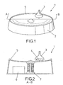
- Figure 1 represents a perspective view of the object of the invention, corresponding to a low consumption dynamic magnetic motor.
- Figure 2 shows a sectional view along the A-B line of the object represented in Figure 1.
- Figure 3 finally corresponds to a functional diagram view.
-
- In view of these figures, it can be observed how the low consumption dynamic magnetic motor (1) is made up of a circular body (2) adopting a configuration approximating a cone frustum, provided with a slight central bulge and provided with a perimetral rim (5) in the upper portion for the purpose of preventing a spinning top (3), manufactured in plastic material and provided with a magnet (4) and located in its inner area, from leaving to the outside, having a battery (6) in the inner portion and a coil (7) with two winding turns around a steel pipe core.
- A transistor (13) acting as a switch has been provided in the circuit.
- The rotor can be mobilized with a conventional electric motor, with a mechanical arm for starting it up again in the event of an accidental shut off, and this dynamic motor can be provided with blades around its main shaft for the purpose of allowing its actuation as a fan or cooling system.
- The invention has low voltage power supply (10), as shown in Figure 3, the power supply being direct current and a conventional battery would be enough for low amperage motors.
- When the rotor (3) is in motion rotating on its main shaft, the magnet (4) generates an electromagnetic field in the circuit (11) of the coil (7), which will amplify the magnetic field created by the rotor (3).
- The battery, or any direct current power source, will maintain the electromagnetic field generated by the coil (7), which will repel the magnetized disc (4) of the rotor (3), generating a kinetic energy power supply in this rotor.
- The coil (7) thus supplies electromagnetic energy coming from the electrical power supply source (10) which the rotor converts into kinetic energy with which it can overcome losses due to friction and increase its rotating speed.
- The electromagnet of the coil (7) will generate a magnetic torque which will act on the poles of the magnetized disc of the rotor, generating a dynamic interaction torque perpendicular to the previous one, which will maintain the rotor dynamics.
- As previously stated, the transistor (13) acts as a simple switch such that when the rotor stops (3), the motor shuts off and the power supply (10) is cut off, with the subsequent savings.
- According to Figure 2, it can be observed that when one of the poles of the magnet (4), for example the south pole, approaches the coil, current is generated in the outer winding (11) with a direction such that it makes the base of the transistor become positive, causing an emitter-collector current flowing throughout the winding (12).
- The connections must be made such that the current (12) flows in a direction opposite to that of (11), and the reason resides in Lenz's Law, i.e. the current induced in (11) will generate a new current in (12) of the opposite direction to that of (11).
- The effects of the influence of the magnetic field in (11) in relation to that of (12) are of no interest in this case, since these magnetic fields are weak in comparison to that of the electromagnet (7).
- The rotor (3) adopting the form of a spinning top manufactured in plastic material can have any dimension according to the power which is desired, its being an NPN or PNP circuit being of no consequence, since these simply affect polarity and directions, with no change in the final result.
- The windings of the coil will be of very small cable section and with about 4,000 winding turns surrounding a cylindrical iron pipe.
- The rotating speed of the rotor may be widely variable but no less than 3,000 revolutions per minute.
Claims (4)
- A reduced consumption dynamic magnetic motor, either provided with blades in its rotor or not, having conventional starting means on the rotor and optionally provided with a mechanical arm for its automatic recovery in the event of an accidental shut off (1), possibly having a protective perimetral wire mesh cage, characterized by being made up of a body adopting the shape of a cup or cone frustum (2), provided with a slight central bulge, the upper surface having a perimetral rim (5) limiting the movement area of the rotor (3), which can adopt a spinning top shape and internally incorporating a disc or flywheel in its central portion, configured as magnetized iron (4) located transversally to the axis of revolution, the rotor being manufactured in plastic material, rotating on its main shaft and perpendicularly to the surface of the cup (2).
- A reduced consumption dynamic magnetic motor according to the first claim, characterized in that provided inside the cup (2) is the incorporation of a cup (7) with two winding turns around a steel pipe core, incorporating a transistor (13) and a direct current power supply (10), as well as a battery (6).
- A reduced consumption dynamic magnetic motor according to the previous claims, characterized in that the motor shuts off and starts up according to whether the rotor (3) enters or exits the electromagnetic field generated by the coil (7) located in the center of the base of the body (2), the transistor acting as a switch.
- A reduced consumption dynamic magnetic motor according to the previous claims, characterized in that the windings of the coil (7) are 4,000 winding turns of reduced section surrounding a cylindrical pipe.
Applications Claiming Priority (3)
| Application Number | Priority Date | Filing Date | Title |
|---|---|---|---|
| ES200201790A ES2199084B1 (en) | 2002-07-30 | 2002-07-30 | MAGNETIC MOTOR DYNAMIC REDUCED CONSUMPTION. |
| ES200201790 | 2002-07-30 | ||
| PCT/ES2003/000266 WO2004013948A1 (en) | 2002-07-30 | 2003-06-02 | Reduced-consumption dynamic magnetic motor |
Publications (1)
| Publication Number | Publication Date |
|---|---|
| EP1548920A1 true EP1548920A1 (en) | 2005-06-29 |
Family
ID=31198112
Family Applications (1)
| Application Number | Title | Priority Date | Filing Date |
|---|---|---|---|
| EP03766415A Withdrawn EP1548920A1 (en) | 2002-07-30 | 2003-06-02 | Reduced-consumption dynamic magnetic motor |
Country Status (4)
| Country | Link |
|---|---|
| EP (1) | EP1548920A1 (en) |
| AU (1) | AU2003232858A1 (en) |
| ES (1) | ES2199084B1 (en) |
| WO (1) | WO2004013948A1 (en) |
Cited By (1)
| Publication number | Priority date | Publication date | Assignee | Title |
|---|---|---|---|---|
| WO2022198444A1 (en) * | 2021-03-23 | 2022-09-29 | 中国科学院深圳先进技术研究院 | Magnetic levitation system |
Families Citing this family (1)
| Publication number | Priority date | Publication date | Assignee | Title |
|---|---|---|---|---|
| US9827504B2 (en) | 2012-05-19 | 2017-11-28 | Kenneth E. Olson | Vibratory device for bobble toys |
Family Cites Families (5)
| Publication number | Priority date | Publication date | Assignee | Title |
|---|---|---|---|---|
| US4382245A (en) * | 1978-04-25 | 1983-05-03 | Harrigan Roy Major | Levitation device |
| US5404062A (en) * | 1994-02-17 | 1995-04-04 | Creative Gifts, Inc. | Magnetic levitation device and method |
| DE4409992A1 (en) * | 1994-03-23 | 1995-09-28 | Skf Textilmasch Komponenten | Separate motor drive for shaftless rotor of an open end spinner |
| US5883454A (en) * | 1996-06-28 | 1999-03-16 | Creative Gifts, Inc. | Electormagnetic drive method and apparatus for driving a rotationally stabilized magnetically levitated object |
| JP4969749B2 (en) * | 1999-10-18 | 2012-07-04 | タートルテック・デザイン・インコーポレイテッド | Rotating display spherical device |
-
2002
- 2002-07-30 ES ES200201790A patent/ES2199084B1/en not_active Expired - Fee Related
-
2003
- 2003-06-02 EP EP03766415A patent/EP1548920A1/en not_active Withdrawn
- 2003-06-02 WO PCT/ES2003/000266 patent/WO2004013948A1/en not_active Ceased
- 2003-06-02 AU AU2003232858A patent/AU2003232858A1/en not_active Abandoned
Non-Patent Citations (1)
| Title |
|---|
| See references of WO2004013948A1 * |
Cited By (1)
| Publication number | Priority date | Publication date | Assignee | Title |
|---|---|---|---|---|
| WO2022198444A1 (en) * | 2021-03-23 | 2022-09-29 | 中国科学院深圳先进技术研究院 | Magnetic levitation system |
Also Published As
| Publication number | Publication date |
|---|---|
| AU2003232858A1 (en) | 2004-02-23 |
| WO2004013948A1 (en) | 2004-02-12 |
| ES2199084A1 (en) | 2004-02-01 |
| ES2199084B1 (en) | 2005-06-01 |
Similar Documents
| Publication | Publication Date | Title |
|---|---|---|
| EP1406371B1 (en) | Single-phase motor | |
| US20150130306A1 (en) | Motor | |
| EP1014542A3 (en) | Motor having a rotor with interior split-permanent-magnet | |
| TWI514748B (en) | Brushless DC motor drive circuit | |
| KR20140116258A (en) | Radial and Axial Flux Motor using Integrated Windings | |
| EP1424764A3 (en) | Vehicular generator-motor system | |
| JP2015515846A (en) | Brushless DC motor | |
| EP1182766A4 (en) | Brushless motor | |
| CN103950373A (en) | Electric wheel with built-in suspension flywheel | |
| ATE515827T1 (en) | MAGNETIC MOTOR | |
| JPH023180U (en) | ||
| JP2020524972A (en) | Improved magnetic clutch assembly | |
| CN201904710U (en) | Hall Sensor Brushless Permanent Magnet DC Motor | |
| KR101312204B1 (en) | Outer rotor type brushless dc motor | |
| US20190341827A1 (en) | Method and Apparatus to Drive a Rotor and Generate Electrical Power | |
| TW200640111A (en) | Fan motor and stator thereof | |
| TWI413342B (en) | Motor stator | |
| EP2453550A2 (en) | Stator of a fan motor | |
| WO2018051588A1 (en) | Electric blower | |
| EP2043230A2 (en) | Axial gap motor | |
| EP1843448B1 (en) | Motor | |
| CN107355390B8 (en) | A low-power centrifugal pump directly driven by a permanent magnet synchronous motor | |
| JP7469838B1 (en) | motor | |
| KR101604637B1 (en) | Vaccum motor with generator | |
| WO2004013948A1 (en) | Reduced-consumption dynamic magnetic motor |
Legal Events
| Date | Code | Title | Description |
|---|---|---|---|
| PUAI | Public reference made under article 153(3) epc to a published international application that has entered the european phase |
Free format text: ORIGINAL CODE: 0009012 |
|
| 17P | Request for examination filed |
Effective date: 20050225 |
|
| AK | Designated contracting states |
Kind code of ref document: A1 Designated state(s): AT BE BG CH CY CZ DE DK EE ES FI FR GB GR HU IE IT LI LU MC NL PT RO SE SI SK TR |
|
| AX | Request for extension of the european patent |
Extension state: AL LT LV MK |
|
| DAX | Request for extension of the european patent (deleted) | ||
| RBV | Designated contracting states (corrected) |
Designated state(s): DE FR GB |
|
| STAA | Information on the status of an ep patent application or granted ep patent |
Free format text: STATUS: THE APPLICATION IS DEEMED TO BE WITHDRAWN |
|
| 18D | Application deemed to be withdrawn |
Effective date: 20110103 |