EP1548800A2 - Free-standing stem barrel supported mount for hid lamp - Google Patents
Free-standing stem barrel supported mount for hid lamp Download PDFInfo
- Publication number
- EP1548800A2 EP1548800A2 EP04027917A EP04027917A EP1548800A2 EP 1548800 A2 EP1548800 A2 EP 1548800A2 EP 04027917 A EP04027917 A EP 04027917A EP 04027917 A EP04027917 A EP 04027917A EP 1548800 A2 EP1548800 A2 EP 1548800A2
- Authority
- EP
- European Patent Office
- Prior art keywords
- frame member
- shaped clip
- affixed
- light source
- metal strap
- Prior art date
- Legal status (The legal status is an assumption and is not a legal conclusion. Google has not performed a legal analysis and makes no representation as to the accuracy of the status listed.)
- Granted
Links
Images
Classifications
-
- H—ELECTRICITY
- H01—ELECTRIC ELEMENTS
- H01J—ELECTRIC DISCHARGE TUBES OR DISCHARGE LAMPS
- H01J61/00—Gas-discharge or vapour-discharge lamps
- H01J61/02—Details
- H01J61/30—Vessels; Containers
- H01J61/34—Double-wall vessels or containers
-
- H—ELECTRICITY
- H01—ELECTRIC ELEMENTS
- H01J—ELECTRIC DISCHARGE TUBES OR DISCHARGE LAMPS
- H01J5/00—Details relating to vessels or to leading-in conductors common to two or more basic types of discharge tubes or lamps
- H01J5/48—Means forming part of the tube or lamp for the purpose of supporting it
-
- H—ELECTRICITY
- H01—ELECTRIC ELEMENTS
- H01J—ELECTRIC DISCHARGE TUBES OR DISCHARGE LAMPS
- H01J61/00—Gas-discharge or vapour-discharge lamps
- H01J61/02—Details
- H01J61/24—Means for obtaining or maintaining the desired pressure within the vessel
- H01J61/26—Means for absorbing or adsorbing gas, e.g. by gettering; Means for preventing blackening of the envelope
Definitions
- This invention relates to lamps and more particularly to structures for mounting light source capsules within outer envelopes. Still more particularly it relates to mount assemblies that are economical to fabricate, suitable for automation, and easily mounted to low-wattage lamps.
- Mount assemblies for arc discharge lamps usually employ a discharge vessel mounted upon a frame.
- the frame is generally mounted by means of clips to the flare and extends longitudinally to the opposite end of a lamp envelope where it is held in place by either snubbers embracing the envelope wall or a ring, which engages a dimple, formed in the wall envelope.
- the flare itself comprises a tubular body that can carry the exhaust tubulation and seals the in-leads in a pinch seal.
- Previous assemblies have used bands and frame assemblies that were crimped onto a stem. Often, these assemblies were purchased parts that occasionally suffered damage in shipping. Further, the crimping and strapping operations necessary to mount the assembly to the stem have not been reasonably automatable. Such assemblies are expensive and require a great deal of manual operations to complete. The repetitious hand operations also had unacceptable ergonomic issues.
- the clip had a given height H and an inside diameter D.
- a mount assembly for a lamp that included a "U" shaped frame member extending the length of the mount assembly, from the flare to the opposite end of the lamp envelope.
- the frame had a first leg attached to one of the flaps and a second leg attached to the other of the flaps.
- This construction while working well, required a special lamp envelope having multiple diameters. This construction is shown in pending U.S. Patent Application Serial No. 10/155,541, filed May 24, 2002 and assigned to the assignee of the present invention.
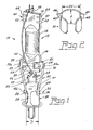
- a mount assembly 10 for a lamp that comprises a light source 12 having two ends 14, 16 separated by a hollow middle portion 18.
- Light source capsule 12 can be an arc discharge vessel and the ends 14 and 16 are substantially parallelepipedial.
- the ends 14 and 16 are also provided with alignment segments 60 in the form of spaced apart beads 62 and 64.
- a metal strap 20 surrounds one of the ends, for example, 14, and is positioned between the beads 62 and 64, and has first and second oppositely disposed affixation areas, 22, 24; which can be in the form of extensions 22a and 24a.
- a glass stem 26 has a tubular first portion 28 with an outside diameter D.
- a substantially C-shaped clip 30, shown separately in Fig. 2, is mounted upon the tubular first portion 28.
- the C-shaped clip 30 has a given height H and an inside diameter D1 that is smaller than the outside diameter D whereby the clip frictionally engages the tubular first portion.
- a first frame member 32 has a proximal terminus 34 affixed to the substantially C-shaped clip 30 and a second frame member 35 has a proximal terminus 36 affixed to the substantially C-shaped clip 30 opposite the first frame member 32.
- the first frame member 32 has a distal terminus 38 affixed to one of the affixation areas on metal strap 20, for example, area 22, and second frame member 35 has a distal terminus 40 affixed to the other of the affixation areas, for example 24.
- the first and second frame members 32 and 35 and the metal strap 20 constitute the sole support for the light source 12.
- the C-shaped clip 30 has oppositely located cutouts 42, 44, providing extending flaps 46, 48 to which are attached the proximal termini 32, 35.
- the glass stem 26 has a second portion 50 formed as a pinch seal and containing the electrical lead-ins 52, and 54. These lead-ins are operatively connected to electrodes 56 and 58, located in opposite ends of the light source 12.
- a getter 70 is attached to the metal strap 20 for removing unwanted gases formed during operation of the lamp. This position of the getter provides the desired gettering action whether the lamp is operated base up or base down. Although the temperature of the getter will be about 100° C hotter during base up use it will still be within the desired operating range of between 335 and 450° C.
Landscapes
- Vessels And Coating Films For Discharge Lamps (AREA)
Abstract
Description
Claims (8)
- A mount assembly for a lamp comprising:a light source having two ends separated by a hollow middle portion;a metal strap surrounding one of said ends and having first and second oppositely disposed affixation areas;a glass stem having a tubular first portion with an outside diameter D;a substantially C-shaped clip mounted upon said tubular first portion, said C-shaped clip having a given height H and an inside diameter D1 that is smaller than said outside diameter D whereby said clip frictionally engages said tubular first portion; anda first frame member having a proximal terminus affixed to said substantially C-shaped clip and a second frame member having a proximal terminus affixed to said substantially C-shaped clip opposite said first frame member, said first frame member having a distal terminus affixed to one of said affixation areas on said metal strap and said second frame member having a distal terminus affixed to the other of said affixation areas, said first andsecond frame members and said metal strap constituting the sole support for said light source.
- The mount assembly of Claim 1 wherein a pair of substantially oppositely located cutouts is formed in said substantially C-shaped clip, each cutout providing an extending flap projecting away from said substantially C-shaped clip and wherein said first frame member proximal terminus is attached to one of said flaps and said second frame member proximal terminus is affixed to the other of said flaps.
- The mount assembly of Claim 2 wherein said glass stem has a second portion formed as a pinch seal and having a pair of electrical lead-ins sealed therein.
- The mount assembly of Claim 3 wherein said light source has electrodes in opposite ends and said electrical lead-ins are operatively connected to said electrodes.
- The mount assembly of Claim 4 wherein said two ends of said light source are substantially parallelepipedonal.
- The mount assembly of Claim 5 wherein at least one of said ends is provided with alignment segments for orientating said metal strap.
- The mount assembly of Claim 6 wherein said alignment segments comprise spaced apart beads.
- A mount assembly for a lamp comprising:a light source having two ends separated by a hollow middle portion;a metal strap surrounding one of said ends and having first and second oppositely disposed affixation areas;a glass stem having a tubular first portion with an outside diameter D and a second portion formed as a pinch seal having at least one dimension greater than D;a substantially C-shaped clip mounted upon said tubular first portion, said C-shaped clip having a given height H and an inside diameter D1 that is smaller than said outside diameter D whereby said clip frictionally engages said first portion;a pair of substantially oppositely located cutouts formed in said substantially C-shaped clip, each cutout providing an extending flap projecting away from said substantially C-shaped clip; anda first frame member having a proximal terminus affixed to a first of said flaps and a second frame member having a proximal terminus affixed to a second of said flaps, said first frame member having a distal terminus affixed to one of said affixation areas on said metal strap and said second frame member having a distal terminus affixed to the other of said affixation areas, said first and second frame members and said metal strap constituting the sole support for said light source.
Applications Claiming Priority (4)
| Application Number | Priority Date | Filing Date | Title |
|---|---|---|---|
| US53164203P | 2003-12-22 | 2003-12-22 | |
| US531642P | 2003-12-22 | ||
| US814468 | 2004-03-31 | ||
| US10/814,468 US7038366B2 (en) | 2003-12-22 | 2004-03-31 | Free-standing stem barrel supported mount for hid lamp |
Publications (3)
| Publication Number | Publication Date |
|---|---|
| EP1548800A2 true EP1548800A2 (en) | 2005-06-29 |
| EP1548800A3 EP1548800A3 (en) | 2007-03-07 |
| EP1548800B1 EP1548800B1 (en) | 2009-03-04 |
Family
ID=34556579
Family Applications (1)
| Application Number | Title | Priority Date | Filing Date |
|---|---|---|---|
| EP04027917A Expired - Lifetime EP1548800B1 (en) | 2003-12-22 | 2004-11-24 | Free-standing stem barrel supported mount for hid lamp |
Country Status (5)
| Country | Link |
|---|---|
| US (1) | US7038366B2 (en) |
| EP (1) | EP1548800B1 (en) |
| JP (1) | JP4636868B2 (en) |
| CA (1) | CA2482297A1 (en) |
| DE (1) | DE602004019752D1 (en) |
Cited By (1)
| Publication number | Priority date | Publication date | Assignee | Title |
|---|---|---|---|---|
| US8827724B2 (en) | 2008-07-07 | 2014-09-09 | Molex Incorporated | Board connector |
Family Cites Families (11)
| Publication number | Priority date | Publication date | Assignee | Title |
|---|---|---|---|---|
| US2830210A (en) * | 1954-09-16 | 1958-04-08 | Gen Electric | Arc tube support |
| JPS4711185U (en) * | 1971-02-25 | 1972-10-09 | ||
| DE2606665C2 (en) * | 1976-02-19 | 1986-09-11 | Standard Elektrik Lorenz Ag, 7000 Stuttgart | Method of aligning a multi-beam electron gun in assembling a cathode ray tube |
| JPS54124364U (en) * | 1978-02-20 | 1979-08-30 | ||
| US5521458A (en) * | 1995-04-25 | 1996-05-28 | Osram Sylvania Inc. | Electric discharge lamp assembly |
| US6188164B1 (en) * | 1997-05-09 | 2001-02-13 | Osram Sylvania Inc. | Mount assembly for arc lamp |
| US6291933B1 (en) * | 1999-09-24 | 2001-09-18 | Philips Electronics North America Corporation | Metal halide lamp with ARC tube secured to frame by clips passing through protective sleeve |
| US6575415B1 (en) * | 2002-05-24 | 2003-06-10 | Osram Sylvania Inc. | Stem clip for high intensity discharge lamp |
| US6771008B2 (en) * | 2002-09-30 | 2004-08-03 | Osram Sylvania Inc. | Stem clip for high intensity discharge lamp |
| US6963158B2 (en) * | 2003-08-15 | 2005-11-08 | Osram Sylvania Inc. | Mount assembly for discharge lamps |
| US20050046325A1 (en) * | 2003-08-26 | 2005-03-03 | Mccullough Ebon L. | Press-on stem clip for hid lamp |
-
2004
- 2004-03-31 US US10/814,468 patent/US7038366B2/en not_active Expired - Lifetime
- 2004-09-23 CA CA002482297A patent/CA2482297A1/en not_active Abandoned
- 2004-11-24 EP EP04027917A patent/EP1548800B1/en not_active Expired - Lifetime
- 2004-11-24 DE DE602004019752T patent/DE602004019752D1/en not_active Expired - Lifetime
- 2004-12-16 JP JP2004365066A patent/JP4636868B2/en not_active Expired - Fee Related
Cited By (1)
| Publication number | Priority date | Publication date | Assignee | Title |
|---|---|---|---|---|
| US8827724B2 (en) | 2008-07-07 | 2014-09-09 | Molex Incorporated | Board connector |
Also Published As
| Publication number | Publication date |
|---|---|
| JP2005183389A (en) | 2005-07-07 |
| EP1548800A3 (en) | 2007-03-07 |
| JP4636868B2 (en) | 2011-02-23 |
| CA2482297A1 (en) | 2005-06-22 |
| EP1548800B1 (en) | 2009-03-04 |
| US7038366B2 (en) | 2006-05-02 |
| US20050218772A1 (en) | 2005-10-06 |
| DE602004019752D1 (en) | 2009-04-16 |
Similar Documents
| Publication | Publication Date | Title |
|---|---|---|
| US5252885A (en) | Metal halide arc discharge lamp assembly | |
| US5136204A (en) | Metal halide arc discharge lamp assembly | |
| US6268698B1 (en) | Capacitive glow starting of high intensity discharge lamps | |
| US6157131A (en) | Metal halide lamp with frame members | |
| EP1548800B1 (en) | Free-standing stem barrel supported mount for hid lamp | |
| US5859492A (en) | Electrode rod support for short arc lamp | |
| US5576598A (en) | Lamp with glass sleeve and method of making same | |
| US6329742B1 (en) | Metal halide lamp with metal frame supporting a protective sleeve | |
| US5521458A (en) | Electric discharge lamp assembly | |
| US4620125A (en) | Low wattage metal halide lamp with inverted domed sleeve | |
| US6147440A (en) | Low wattage lamp having formed arc tube in aluminosilicate outer jacket | |
| US6737791B2 (en) | Snap-on spring clip for ceramic hid lamp | |
| US7619350B2 (en) | Arc discharge vessel having arc centering structure and lamp containing same | |
| US6858976B2 (en) | Spring-clip for hid lamp | |
| GB2103872A (en) | Electric discharge lamp seals | |
| US6628080B1 (en) | Spring clip for lamp with shroud | |
| EP1403905A2 (en) | Snap-on spring clip for ceramic HID lamp | |
| JP5248748B2 (en) | Shroud holder for quartz and ceramic arc tubes | |
| US5757134A (en) | Mica heat shield for high intensity discharge lamp | |
| US6963158B2 (en) | Mount assembly for discharge lamps | |
| CA1246132A (en) | Electrode positioning in metal halide lamps | |
| US6717338B2 (en) | Frame mount for high intensity discharge lamp | |
| US20050046325A1 (en) | Press-on stem clip for hid lamp | |
| JP2000223066A (en) | Metal halide lamps and lighting equipment |
Legal Events
| Date | Code | Title | Description |
|---|---|---|---|
| PUAI | Public reference made under article 153(3) epc to a published international application that has entered the european phase |
Free format text: ORIGINAL CODE: 0009012 |
|
| AK | Designated contracting states |
Kind code of ref document: A2 Designated state(s): AT BE BG CH CY CZ DE DK EE ES FI FR GB GR HU IE IS IT LI LU MC NL PL PT RO SE SI SK TR |
|
| AX | Request for extension of the european patent |
Extension state: AL HR LT LV MK YU |
|
| PUAL | Search report despatched |
Free format text: ORIGINAL CODE: 0009013 |
|
| AK | Designated contracting states |
Kind code of ref document: A3 Designated state(s): AT BE BG CH CY CZ DE DK EE ES FI FR GB GR HU IE IS IT LI LU MC NL PL PT RO SE SI SK TR |
|
| AX | Request for extension of the european patent |
Extension state: AL HR LT LV MK YU |
|
| 17P | Request for examination filed |
Effective date: 20070822 |
|
| AKX | Designation fees paid |
Designated state(s): BE DE HU NL |
|
| GRAP | Despatch of communication of intention to grant a patent |
Free format text: ORIGINAL CODE: EPIDOSNIGR1 |
|
| GRAS | Grant fee paid |
Free format text: ORIGINAL CODE: EPIDOSNIGR3 |
|
| GRAA | (expected) grant |
Free format text: ORIGINAL CODE: 0009210 |
|
| AK | Designated contracting states |
Kind code of ref document: B1 Designated state(s): BE DE HU NL |
|
| REF | Corresponds to: |
Ref document number: 602004019752 Country of ref document: DE Date of ref document: 20090416 Kind code of ref document: P |
|
| REG | Reference to a national code |
Ref country code: HU Ref legal event code: AG4A Ref document number: E005665 Country of ref document: HU |
|
| PLBE | No opposition filed within time limit |
Free format text: ORIGINAL CODE: 0009261 |
|
| STAA | Information on the status of an ep patent application or granted ep patent |
Free format text: STATUS: NO OPPOSITION FILED WITHIN TIME LIMIT |
|
| 26N | No opposition filed |
Effective date: 20091207 |
|
| PGFP | Annual fee paid to national office [announced via postgrant information from national office to epo] |
Ref country code: HU Payment date: 20121120 Year of fee payment: 9 Ref country code: DE Payment date: 20121121 Year of fee payment: 9 |
|
| PGFP | Annual fee paid to national office [announced via postgrant information from national office to epo] |
Ref country code: BE Payment date: 20121122 Year of fee payment: 9 |
|
| PGFP | Annual fee paid to national office [announced via postgrant information from national office to epo] |
Ref country code: NL Payment date: 20121120 Year of fee payment: 9 |
|
| BERE | Be: lapsed |
Owner name: OSRAM SYLVANIA INC. Effective date: 20131130 |
|
| REG | Reference to a national code |
Ref country code: DE Ref legal event code: R119 Ref document number: 602004019752 Country of ref document: DE |
|
| REG | Reference to a national code |
Ref country code: NL Ref legal event code: V1 Effective date: 20140601 |
|
| PG25 | Lapsed in a contracting state [announced via postgrant information from national office to epo] |
Ref country code: NL Free format text: LAPSE BECAUSE OF NON-PAYMENT OF DUE FEES Effective date: 20140601 Ref country code: DE Free format text: LAPSE BECAUSE OF NON-PAYMENT OF DUE FEES Effective date: 20140603 |
|
| REG | Reference to a national code |
Ref country code: DE Ref legal event code: R119 Ref document number: 602004019752 Country of ref document: DE Effective date: 20140603 |
|
| PG25 | Lapsed in a contracting state [announced via postgrant information from national office to epo] |
Ref country code: HU Free format text: LAPSE BECAUSE OF NON-PAYMENT OF DUE FEES Effective date: 20131125 Ref country code: BE Free format text: LAPSE BECAUSE OF NON-PAYMENT OF DUE FEES Effective date: 20131130 |