EP1548778A1 - Vacuum switchgear system - Google Patents
Vacuum switchgear system Download PDFInfo
- Publication number
- EP1548778A1 EP1548778A1 EP04030164A EP04030164A EP1548778A1 EP 1548778 A1 EP1548778 A1 EP 1548778A1 EP 04030164 A EP04030164 A EP 04030164A EP 04030164 A EP04030164 A EP 04030164A EP 1548778 A1 EP1548778 A1 EP 1548778A1
- Authority
- EP
- European Patent Office
- Prior art keywords
- iron core
- force
- operation units
- switches
- motive force
- Prior art date
- Legal status (The legal status is an assumption and is not a legal conclusion. Google has not performed a legal analysis and makes no representation as to the accuracy of the status listed.)
- Granted
Links
- 230000007246 mechanism Effects 0.000 claims abstract description 35
- XEEYBQQBJWHFJM-UHFFFAOYSA-N Iron Chemical group [Fe] XEEYBQQBJWHFJM-UHFFFAOYSA-N 0.000 claims description 73
- 230000005540 biological transmission Effects 0.000 claims description 5
- 238000000926 separation method Methods 0.000 claims description 2
- 239000004020 conductor Substances 0.000 description 29
- 229910052742 iron Inorganic materials 0.000 description 4
- 239000000919 ceramic Substances 0.000 description 2
- 238000006073 displacement reaction Methods 0.000 description 2
- 238000009434 installation Methods 0.000 description 2
- 238000009413 insulation Methods 0.000 description 2
- RYGMFSIKBFXOCR-UHFFFAOYSA-N Copper Chemical compound [Cu] RYGMFSIKBFXOCR-UHFFFAOYSA-N 0.000 description 1
- 230000002411 adverse Effects 0.000 description 1
- 238000010276 construction Methods 0.000 description 1
- 229910052802 copper Inorganic materials 0.000 description 1
- 239000010949 copper Substances 0.000 description 1
- 230000009189 diving Effects 0.000 description 1
- 230000005281 excited state Effects 0.000 description 1
- 230000001771 impaired effect Effects 0.000 description 1
- 239000002184 metal Substances 0.000 description 1
- 229910052751 metal Inorganic materials 0.000 description 1
- 238000001179 sorption measurement Methods 0.000 description 1
- 229910001220 stainless steel Inorganic materials 0.000 description 1
- 239000010935 stainless steel Substances 0.000 description 1
Images



Classifications
-
- H—ELECTRICITY
- H01—ELECTRIC ELEMENTS
- H01H—ELECTRIC SWITCHES; RELAYS; SELECTORS; EMERGENCY PROTECTIVE DEVICES
- H01H33/00—High-tension or heavy-current switches with arc-extinguishing or arc-preventing means
- H01H33/02—Details
- H01H33/04—Means for extinguishing or preventing arc between current-carrying parts
- H01H33/14—Multiple main contacts for the purpose of dividing the current through, or potential drop along, the arc
-
- H—ELECTRICITY
- H01—ELECTRIC ELEMENTS
- H01H—ELECTRIC SWITCHES; RELAYS; SELECTORS; EMERGENCY PROTECTIVE DEVICES
- H01H3/00—Mechanisms for operating contacts
- H01H3/32—Driving mechanisms, i.e. for transmitting driving force to the contacts
- H01H3/46—Driving mechanisms, i.e. for transmitting driving force to the contacts using rod or lever linkage, e.g. toggle
-
- H—ELECTRICITY
- H01—ELECTRIC ELEMENTS
- H01H—ELECTRIC SWITCHES; RELAYS; SELECTORS; EMERGENCY PROTECTIVE DEVICES
- H01H31/00—Air-break switches for high tension without arc-extinguishing or arc-preventing means
- H01H31/003—Earthing switches
-
- H—ELECTRICITY
- H01—ELECTRIC ELEMENTS
- H01H—ELECTRIC SWITCHES; RELAYS; SELECTORS; EMERGENCY PROTECTIVE DEVICES
- H01H33/00—High-tension or heavy-current switches with arc-extinguishing or arc-preventing means
- H01H33/02—Details
- H01H33/022—Details particular to three-phase circuit breakers
-
- H—ELECTRICITY
- H01—ELECTRIC ELEMENTS
- H01H—ELECTRIC SWITCHES; RELAYS; SELECTORS; EMERGENCY PROTECTIVE DEVICES
- H01H33/00—High-tension or heavy-current switches with arc-extinguishing or arc-preventing means
- H01H33/60—Switches wherein the means for extinguishing or preventing the arc do not include separate means for obtaining or increasing flow of arc-extinguishing fluid
- H01H33/66—Vacuum switches
- H01H33/666—Operating arrangements
- H01H33/6661—Combination with other type of switch, e.g. for load break switches
-
- H—ELECTRICITY
- H01—ELECTRIC ELEMENTS
- H01H—ELECTRIC SWITCHES; RELAYS; SELECTORS; EMERGENCY PROTECTIVE DEVICES
- H01H33/00—High-tension or heavy-current switches with arc-extinguishing or arc-preventing means
- H01H33/60—Switches wherein the means for extinguishing or preventing the arc do not include separate means for obtaining or increasing flow of arc-extinguishing fluid
- H01H33/66—Vacuum switches
- H01H33/666—Operating arrangements
- H01H2033/6668—Operating arrangements with a plurality of interruptible circuit paths in single vacuum chamber
-
- H—ELECTRICITY
- H01—ELECTRIC ELEMENTS
- H01H—ELECTRIC SWITCHES; RELAYS; SELECTORS; EMERGENCY PROTECTIVE DEVICES
- H01H33/00—High-tension or heavy-current switches with arc-extinguishing or arc-preventing means
- H01H33/60—Switches wherein the means for extinguishing or preventing the arc do not include separate means for obtaining or increasing flow of arc-extinguishing fluid
- H01H33/66—Vacuum switches
- H01H33/666—Operating arrangements
- H01H33/6662—Operating arrangements using bistable electromagnetic actuators, e.g. linear polarised electromagnetic actuators
Definitions
- the present invention relates to a vacuum switchgear system, and more particularly to a vacuum switchgear system comprising a plurality of switches accommodated in vacuum containers and an operation unit for operating each of the switchgears, which are suitable for receiving-distributing electric power of an electric power transmission system.
- switchgears As one element for receiving-distribution facilities of an electric power transmission system.
- air insulated switchgears have been widely used; however, gas insulated switchgears using SF 6 gas as an insulating gas are used for aiming at small sized facilities. Since the gas insulated switchgears may give adverse affects on environment, vacuum insulated switchgears using vacuum as an insulating medium are proposed in recent years.
- a vacuum switchgear comprising a plurality of switches for a main circuit accommodated in a vacuum container, a fixed electrode and a movable electrode disposed in opposite relation with each other.
- the movable electrode is connected with the bus side conductor
- the fixed electrode is connected with the load side conductor.
- Each of the electrodes of the main switches is covered with an arc shield.
- Each of the bus side conductors is connected with the movable electrode by means of a flexible conductor (Patent document No. 1) .
- the vacuum switchgear disclosed in the patent document No. 1 which employs vacuum insulation, the insulating distance can be shorter than that of the insulating gas switchgear. Therefore, compact vacuum switchgears can be obtained.
- Patent document 1 Japanese patent laid-open 2000-26868 (pages 3 to 6, Figs. 1 - 3)
- the prior art does not consider the simplification of the structure of an operation unit to be connected with the switch of the switchgear and the relationship between the operation unit and the switch for downsizing the switchgear.
- An object of the present invention is to downsize the switchgear system.
- the present invention provides a vacuum switchgear system for a three phase system, which comprises three switchgears each comprising a vacuum switch and an operation unit, wherein each of the switches is accommodated in a vacuum container and each of the operation units is coaxially connected with an operating rod of each of the switches.
- the operation units of the three switchgears are connected with the adjoining operation units of the switchgears by means of link mechanisms connected with respective driving rods of the operation units.
- Each of the link mechanisms transmits a force of the driving rod assisted by an electro-magnet to the adjoining driving rods through the link mechanisms so that the three switchgears are operated in synchronism in response to a switch-on signal or a switch-off signal.
- the vacuum switchgear system means a system for a three phase power system comprising three vacuum switchgears, wherein the switchgear comprises a vacuum switch accommodated in a vacuum container and an operation unit connected with the switchgear.
- the vacuum switchgear means a vacuum switch comprising a vacuum container and at least one of a main switch or a load break switch, a circuit breaker and an earth switch.
- the switchgear system for a three phase electric power transmission system of the present invention is featured by:
- the vacuum switchgear system of the present invention may contain one or more of the following features.
- a vacuum switchgear system for a three phase electric power transmission system which comprises three switchgears each comprising a vacuum switch and an operation unit, wherein each of the switches is accommodated in a vacuum container and each of the operation units is coaxially connected with an operating rod of each of the switches, wherein the operation units of the three switchgears are connected with the adjoining operation units of the switchgears by means of link mechanisms connected with respective driving rods of the operation units, and wherein each of the link mechanisms transmits a force of the driving rod to the adjoining driving rods through the link mechanisms so that the three switchgears are operated in synchronism in response to a switch-on signal or a switch-off signal.
- each of the link mechanism comprises a swing member one end of which is connected with one end of the driving rod of each of the operation units to convert a reciprocal movement of the driving rod into a swing movement and a connecting rod one end of which is connected with the swing member and the other end is connected with the adjoining swing member to convert the swing movement into a lateral movement.
- the driving rod is assisted by an electromagnet in closing the switches and is assisted by the electromagnet and a permanent magnet in opening the switches.
- the link mechanisms are restrained in the system so as to synchronize the lateral movement of the connecting rods of the three switchgears.
- the base members 128, 134, 148, 158, etc support the link mechanisms in the switchgear system and restrain the link systems in the system.
- the switchgear system comprises three switchgears for three phases each comprising a vacuum switch and an operation unit, wherein each of the switches comprises at least a main switch and an earth switch, and if necessary a circuit breaker, accommodated in a vacuum container, each of the operation units being coaxially connected with an operating rod of each of the switches.
- the operation units of the three switchgears are connected with the adjoining operation units of the switchgear by means of a link mechanism, which has a first member connected with one end of a driving rod of each of the operation units and is disposed to swing around its connecting point as a fulcrum and a second member which is connected with one end of the first member to convert a swing movement of the first member into a lateral movement and transmit the lateral force to the adjoining link mechanisms, whereby the switches in the same phase in the same vacuum container are operated synchronously in response to a switch on signal or a switch off signal.
- a link mechanism which has a first member connected with one end of a driving rod of each of the operation units and is disposed to swing around its connecting point as a fulcrum and a second member which is connected with one end of the first member to convert a swing movement of the first member into a lateral movement and transmit the lateral force to the adjoining link mechanisms, whereby the switches in the same phase in the same vacuum container are operated synchronously in response
- each of the operation units is connected with each of the switches by means of an operating rod, wherein each of the operation units imparts the operating force by magneto-motive force to the operating rod in closing the switches.
- each of the operation units of each of the phases In opening of the switches an operating force by elasticity in the reverse direction with respect to the electro-motive force to the operating rod, each of the operation units of each of the phases being connected with two switches having relation with the operation unit.
- Each of the switches and each of the operation units having relation with the switch are arranged in the closest relation on a same axis with respect to the operating rod.
- Each of the operation units is disposed above each of the switches having relation with the operation unit on an axis of the operating rod.
- Each of the switches comprises three load break switches, a circuit breaker and earth switches.
- the operation units for each switchgear are arranged zigzag in a plane.
- a typical example of the switchgear system of the present invention comprises a circuit breaker 18 of U phase in a vacuum container 10 is connected with an operation unit by means of an operating rod 24 and a driving rod 78; a circuit breaker 18 of V phase in a vacuum container 10 is connected with an operation unit by means of an operating rod 24 and a driving rod 78; and a circuit breaker 18 of W phase in a vacuum container 10 is connected with an operation unit by means of an operating rod 24 and a driving rod 78.
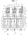
- Fig. 1 is a front view of an essential part of the vacuum switchgear system of an embodiment of the present invention
- Fig. 2 is a plane view of the switchgear system shown in Fig. 1.
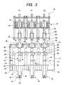
- Fig. 3 is a cross sectional view of the essential part of the switchgear system shown in Fig. 1.
- a three-phase vacuum switchgear system comprises a U phase vacuum container 10, a V phase vacuum container 12 and a W phase vacuum container 14.
- Each of the vacuum containers 10, 12, 14 made of stainless steel accommodates as switches three earth switches 16 and three circuit breakers (or a load break switches) 18 in corresponding to a first line to third line.
- Three operation units 20 for operating the earth switches 16 and three operation units 22 for operating the circuit breakers 18 are disposed above the vacuum containers 10, 12, 14 of the respective phases in corresponding to the earth switches 16 and the circuit breakers 18 of the respective phases.
- the operation units 20, 22 of the respective phases are arranged alternately, and they are arranged zigzag for each phase in a same plane as shown in Fig. 2.
- the operation units 20 are connected with earth switches 16 by means of operating rods 24, and the operation units 22 of the respective phases are connected with the circuit breakers 18 by means of operating rods 24. That is, the operation units 20, 22 of the respective phases are disposed above the vacuum containers 10, 12, 14 in opposite relation with the earth switches 10 and circuit breakers 18, and arranged coaxially with the earth switches 16 and the circuit breakers 18 along the axis of the operating rod 24.
- the operation units 20, 22 of the first line to third line of the respective phases are separately constituted so as to operate independently from each other for the respective phases.
- the operation units 20, 22 of the first line, the operation units 20, 22 of the second line and the operation units 20, 22 of the third line are connected with related operation units by means of link mechanisms 26.
- the operation units 20, 22 of the U phase in the first line are connected with the operation units 20, 22 of the other two phases (V phase and W phase) by means of the link mechanisms. That is, the operation units in different phases are independently operated and synchronously operated in the same phase in the same vacuum container.
- the vacuum containers 10, 12, 14 of the respective phases to be earthed are provided with cable heads 28 in corresponding to the respective circuit breakers 18.
- Each of the cable heads 28 is fixed to the lower plate member 30 in such a state that a part thereof is projected from the bottom of the vacuum container 10, 12, 14 through the through-holes 32 formed in the lower plate member 30.
- Each of the cable heads 28 comprises a conductor 34 of a columnar shape made of copper and an insulating bushing 36 made of ceramics that surrounds the conductor 34. Screw portions 38 are formed at the axial ends of the conductor 34. Cables to be connected with the distribution system are screwed to the screw portions, and one end of the conductor 34 is connected with the load conductor or the bus conductor of the three phases by means of cables. The other end of the conductor 34 is connected with the circuit breaker 18 and also connected with the earth switch 16 by means of the plate conductor 40.
- the circuit breakers 18 of the first line to third line are provided with movable electrodes 42 and fixed electrodes 44 as control switches for opening-closing the conducting circuits connecting between the load conductors and the bus conductors, and the movable electrodes 42 and the fixed electrodes 44 are arranged in opposite relation.
- the upper parts of the movable electrodes 42 connected with the operating rods 24, and also connected with the conductor 48 by means of a flexible conductor 48.
- the plate conductors 48 are arranged over the circuit breakers 18 for the first line to the third line.
- Each of the conductors 48 has a through-hole 50 at a position corresponding to an axis of the circuit breaker 18.
- Each of the operating rods 24 is inserted into the through-hole 50 in reciprocal relation (up and down movement).
- the operating rod 24 is inserted into the through-hole 54 formed in the upper plate member 52 in reciprocal relation (up and down movement).
- the upper part of the operating rod 24 is covered with a cylindrical bellows 56 and a disc base 58; the bellows 58 is fixed to the surface of the upper plate 52.
- Each of the earth switches 16 for earthing each of the circuit breakers comprises a movable electrode 60 and a fixed electrode 62; the electrodes are arranged to oppose to each other.
- the fixed electrode 62 is connected with a conductor 40; a ceramic supporting member 64, which is fixed to the lower plate member 30 supports the fixed electrode side of the conductor 40.
- the movable electrode 60 is connected with the operating rod 24 of the operation unit 20 for the earth switch and connected with the conductor 48 by means of a flexible conductor 68.
- the conductor 68 which is shaped into a plate as same as the plate conductor 48 is arranged over the switches 16 of the first line to the third line.
- the end of the plate conductor is connected with a connecting terminal 70. That is, the earth switches 16 ground the circuit breakers 18 with the conductor 40, the earth switches 16, the flexible conductor 66, the conductor 68 and the earthing terminal 70 upon contacting the movable electrode 60 with the fixed electrode 62.
- the conductor 68 is provided with a through-hole (not shown) for reciprocating the operating rod 24 (up and down movement).
- the bellows 56 and the base surround the operating rod 24.
- each of the operation units 20, 22 of each of the phases is fixed to the fixing plates 72 as shown in Fig. 4.
- a switchboard (not shown) supports the fixing plates 72.
- Each of the operation units 20, 22 of each phase is arranged in a line for each of the first line to the third line.
- each of the operation units 20, 22 comprises an electro-magnet 74, a permanent magnet 76, a driving rod 78, etc.
- Each of the operation units 20, 22 is provided with a trip spring 80 so that operation force of the elastic force in the reverse direction of that of the magneto-motive force is imparted to each of the operating rods 24 upon opening of each of the earth switches 16 and each of the circuit breakers 18. Further, each of the driving rods 78 is connected with the link mechanism 26 for each of the first line, the second line and the third line, thereby to perform three phase operation.
- the electro-magnet 74 is provided with a driving rod 78 as one element, and also provided with a movable iron core (plunger) 82, a fixed iron core 84, a coil bobbin 86, a coil 88, movable disc plates 90, 92, iron supporters 94, 96, 98 of disc form, iron covers 100, 102 of a cylindrical form, a fixed rod 104, etc.
- the lower part of the fixed rod 104 is fixed to the fixing base plate 72 by means of a bolt and a nut.
- the driving rod 78 having a columnar shape is arranged on a coaxial line of the operating rod 24 so that the driving rod 78 is capable of reciprocating up and down in the through-hole or a hollow formed in the center of the iron supporters 94, 96, 98.
- the movable iron core 82 and the movable plates 90, 92 are fixed around the driving rod 78, and a fixed iron core 84 is disposed opposite to the diving rod 78.
- the fixed iron core 78 of an annular shape is fixed to the surface of the iron supporter 98.
- the coil bobbin 86 of an annular shape is disposed to surround the driving rod 78 and the fixed iron core 84.
- the coil bobbin 86 of an annular shape is arranged to surround the driving rod 78 and the fixed iron core 84.
- the supporters 96, 98 support the top end and the bottom end of the coil bobbin.
- An annular coil 88 is disposed in the coil bobbin 86.
- An annular permanent magnet 76 is disposed adjoining the coil 88 and is supported by the supporting plate 96.
- the coil 88 is provided with current in response to a closing signal or an opening signal.
- a magnetic field is generated around the coil 88 a path consisting of movable iron core 82 - fixed iron core 84 - supporting plate 98 - cover 102 - supporting plate 96 - movable iron core 82.
- the magnetic field causes the bottom portion of the movable iron core 82 in the axial direction thereof generate an attractive force in the downward direction so that the movable iron core 82 and the driving rod 78 move toward the fixed iron core 84.
- the movable iron core 82 is adsorbed to the fixed iron core 84 to make contact between the movable iron core 82 and the fixed iron core 84.
- the movable iron core 82 moves toward the fixed iron core 84 in such state that the magneto-motive force generated by the electro-magnets 74 is enhanced, i.e. the adsorption force is enhanced.
- the magneto-motive force generated by the electro-magnets 74 and the permanent magnets 76 is imparted to the driving rod 78 as an operating force for pressing down the driving rod 78 (toward the operating rod 24).
- the lower part of the driving rod 78 is connected with the upper part of the operating rod 24 by means of the connecting rods 106, 108. Therefore, the operating rod 24 moves downward as the driving rod moves downward so that the earth switch 16 or the circuit breaker 18 is switched on.
- the connecting rod 106 is inserted together with the connecting rod 108 into the through-hole 110 formed in the fixing plate 72, thereby to reciprocate (up and down movement).
- the supporting plate 112 is fixed to the upper side of the connecting rod 106.
- a trip spring 80 is disposed between the supporting plate 112 and the fixing plate 72. An elastic force (spring force) is accumulated in the trip spring 80 when the driving rod 78 moves down.
- the trip spring 80 imparts accumulated elastic force (spring force) to the driving rod 18 and the operating rod 24 when the coil 88 becomes non-conduction in response to opening signal or opening operation.
- the operating force of the elastic force is set to be larger than the magneto-motive force of the permanent magnet 76; when the elastic force accumulated in the trip spring is imparted to the driving rod 78 and the operating rod 24 as the operating force, the driving rod 78 and the operating rod 24 moves upward against the magneto-motive force of the permanent magnet 76 to open the earth switch 16 or circuit breaker 18.
- the link mechanism 26 converts operating force along the vertical direction with respect to the operating rod 24 to an operating force in the direction intersecting the driving rod 78 and the operating rod 24, that is, the direction along the horizontal direction so that the operation units of the respective three phases are operated.
- the link mechanism 26 comprises links 114, 116, 118, 120 and connecting rods 122, 124; one end of the link 114 is connected swingingly with the base 128 by means of a pin 126.
- the base 128 is fixed to the supporting plate 94 by means of a bolt and a nut.
- the other end of the link 114 is connected swingingly with one end of the link 116.
- the link 116 is connected swingingly as a link for W phase with the base 134 by means of the pin 132, and the base 134 is fixed to the supporting plate 94 by means of a bolt and a nut.
- the link 116 is disposed swingingly with respect to the pin 132 as a fulcrum.
- Pins 136, 138 are fixed to the link 116 on the line connecting the center of the pin 130 and pin 132, wherein the pin 132 is located between the pins 136 and 138.
- a pin 140 is fixed at a position that intersects the line connecting the center of the pin 130 and the center of the pin 138.
- the driving rod 78 is connected with the pin 136 to swing, and one end of the connecting rod 122 is connected with the pin 140 to swing.
- a stopper 142 is disposed below the pin 138, which is fixed to the supporting plate 94. The pin 138 prevents the link 116 from downward swinging by contacting with the stopper 142, when the operation units 20, 22 of
- the connecting rod 122 is disposed reciprocally along the horizontal direction that intersects the driving rod 78, and the one end of the axis of the connecting rod 122 is connected swingingly with the link 118 by means of the pin 144.
- the link 118 as a link for V phase is swingingly connected with the base 148 by means of the pin 146.
- the base 148 is fixed to the supporting plate 94 by means of a bolt and a nut.
- the link 118 is disposed swingingly with respect to the pin 146 as a fulcrum.
- the pin 150 is fixed on the line connecting the center of the pin 146 and the center of the pin 144.
- the pin 152 is fixed in the direction interesting the line connecting the center of the pin 146 and the center of the pin 150.
- the pin 152 is connected swingingly with the driving rod 78, and the pin 150 is connected swingingly with the connecting rod 124.
- the connecting rod 124 is disposed swingingly in the direction that intersects the driving rod 78 and the operating rod 24, i.e. the horizontal direction.
- One end of the oprtating rod 24 in the axial direction is swingingly connected with the pin 154 of the link 120.
- the link 120 as a link for U phase is provided with the pin 156; the pin 156 is connected swingingly with the base 158.
- the base 156 is fixed to the supporting plate 94 by means of a bolt and a nut.
- the link 120 is disposed swingingly with respect to the pin 156 as a fulcrum.
- the pin 160 is fixed in the direction perpendicular to the line connecting the center of the pin 154 and the pin 156.
- the pin 160 is connecting swingingly with the end portion of the driving rod 78.
- the operation units 20, 22 of each of the phases are switched on, the magneto-motive force generated from the electro-magnets 74 and the permanent magnets 76 is given the driving rod 78 and the operating rod 24, and if the operation units 20, 22 of each of the phases are switched off, the elastic force accumulated in the trip spring is given the driving rod 78 and the operating rod 24. Accordingly, the operation units 20, 22 can be made smaller than the operation units using only elastic force of springs.
- the operation units of the respective phases are constituted by the same elements, the elements can be shared , and assembly work is simplified.
- the distance between the operation units 20, 22 and the vacuum containers 10, 12, 14 can be made small so that the switchgears and the installation area can be made small.
- the distance between the operation units 20, 22 can be made small so that the installation area can be made further small.
- the earth switches 16 and the circuit breakers 18 of the respective phases are accommodated in separate vacuum containers; the earth switches 16 and the circuit breakers 18 of the respective phases can be accommodated in a single vacuum container.
- the permanent magnets 76 can be omitted if the electro magnets generate the magneto-motive force of a sufficient strength.
- the coils of the electro-magnets 20, 22 are made switched off (non-conductive) when the operation units 20, 22 are switched off, current is supplied to the coils 88 of the operation units 20, 22 in the direction opposite to that of switching on, the magneto-motive force whose direction is opposite to that of switching on is generated from the electro-magnet 74 and the magneto-motive force is given the driving rod 78.
- the trip spring having a smaller elastic force (spring force) than the spring in the former embodiment can be employed.
- the arc shields shield metal vapor generated at the time of contacting and separating of the electrodes.
Landscapes
- Physics & Mathematics (AREA)
- Electromagnetism (AREA)
- Driving Mechanisms And Operating Circuits Of Arc-Extinguishing High-Tension Switches (AREA)
- Gas-Insulated Switchgears (AREA)
- High-Tension Arc-Extinguishing Switches Without Spraying Means (AREA)
Abstract
Description
(Patent document 1); Japanese patent laid-open 2000-26868
(pages 3 to 6, Figs. 1 - 3)
Claims (15)
- A vacuum switchgear system for a three phase electric power transmission system, which comprises three switchgears each comprising a vacuum switch and an operation unit, wherein each of the vacuum switches comprises a vacuum container and at least a main switch and earth switch and each of the operation units is coaxially connected with an operating rod of each of the switches, wherein the operation units of each of the switchgears are connected with the adjoining operation units of the switchgear in the same phase by means of a link mechanism connected with respect to driving rods of the operation units, and wherein the link mechanism transmits a force of the driving rod to the adjoining driving rods so that the switches in the same phase are operated in synchronism in response to a switch-on signal or a switch-off signal.
- The vacuum switchgear system according to claim 1, wherein each of the link mechanism comprises a swing member one end of which is connected with one end of the driving rod of each of the operation units to convert a reciprocal movement of the driving rod into a swing movement and a connecting rod one end of which is connected with the swing member and the other end is connected with the adjoining swing member to convert the swing movement into a lateral movement.
- The vacuum switchgear system according to claim 1, wherein the driving rod is assisted by an electromagnet in closing the switches and is assisted by the electromagnet and a permanent magnet in opening the switches.
- The vacuum switchgear system according to claim 1, wherein the link mechanisms are restrained in the system so as to synchronize the lateral movement of the connecting rods of the three switchgears.
- A vacuum switchgear system, which comprises three switchgears for three phases each comprising a vacuum switch and an operation unit, wherein each of the switches comprises an earth switch and a circuit breaker accommodated in a vacuum container, each of the operation units being coaxially connected with an operating rod of each of the switches, wherein the operation units of the three switchgears are connected with the adjoining operation units of the switchgears by means of link mechanisms, each of the link mechanisms having a first member which is connected with one end of a driving rod of each of the operation units and is disposed to swing around its connecting point as a fulcrum and a second member which is connected with one end of the first member to convert a swing movement of the first member into a lateral movement and transmit the lateral force to the adjoining link mechanisms, whereby the three switchgears are operated synchronously in response to a switch on signal or a switch off signal.
- The vacuum switchgear system according to claim 1, wherein each of the operation units being connected with each of the switches by means of an operating rod, wherein each of the operation units imparts the operating force by magneto-motive force to the operating rod in closing the switches.
- The vacuum switchgear system according to claim 1, wherein in opening of the switches an operating force by elasticity in the reverse direction with respect to the electro-motive force to the operating rod, each of the operation units of each of the phases being connected with two switches having relation with the operation unit.
- The vacuum switchgear system according to claim 1, wherein each of the switches and each of the operation units having relation with the switch are arranged in the closest relation on a same axis with respect to the operating rod.
- The vacuum switchgear system according to claim 1, wherein each of the operation units is disposed above each of the switches having relation with the operation unit on an axis of the operating rod.
- The vacuum switchgear system according to claim 1, wherein each of the switches comprises three load break switches, a circuit breaker and earth switches.
- The vacuum switchgear system according to claim 10, wherein the operation units for each switchgear are arranged zigzag in a plane.
- The vacuum switchgear according to claim 1, wherein each of the plurality of operation units comprises a driving rod connected with the operating rod, one end of which is disposed in a coaxial relation with the operating rod in a manner as to reciprocate; a movable iron core fixed to the driving rod; a fixed iron core disposed at a position which is closer to the operating rod than the movable iron core; electro-magnets arranged around the movable iron core and the fixed iron core to generate electro-motive force in response to a closing signal or an opening signal, whereby the electro-motive force is imparted to the driving rods as a force for contacting the movable iron core and the fixed iron core and generation of the electro-motive force in response to the opening signal or opening operation is stopped; and trip springs each connected with the driving rod for accumulating elastic force by movement of the driving rod due to generation of the electro-motive force, whereby the accumulated force is imparted to the movable iron core and the fixed iron core as an operating force to separate them when the generation of the electro-motive force is stopped.
- The vacuum switchgear according to claim 1, wherein each of the plurality of operation units comprises a driving rod connected in a coaxial relation with each of the operating rod and in reciprocating relation with each of the operating rod at one end thereof, a movable iron core fixed to the driving rod, a fixed iron core disposed opposite to the movable iron core at a position closer to the operating rod than to the movable rod, electro-magnets arranged around the movable iron core and the fixed iron core for generating electro-motive force in response to a closing signal or an closing operation so that a first electro-motive force is imparted to the driving rod thereby to contact the movable iron core and the fixed iron core and in response to an opening signal or an opening operation a second electro-motive force is generated in the direction opposite to the first electro-motive force, and trip springs each of which is connected with the driving rod and accumulates elastic force by movement of the movable iron core and the fixed iron core so as to contact them, and when an electro-motive force in the second electro-motive force is generated, the separation force is imparted to the operating rod.
- The vacuum switchgear according to claim 1, wherein each of the plurality of operation units comprises a driving rod one end of which is connected with each of the operating rods in coaxial relation for reciprocating, a movable iron core, a fixed iron core disposed at a position closer to the operating rod than to the movable iron core, electro-magnets arranged around the movable iron core and the fixed iron core, whereby magneto-motive force is generated in response to a closing signal or a closing operation, and whereby the magneto-motive force is imparted to the driving rod in response to contact the movable iron core and the fixed iron core or to stop the generation of magneto-motive force in response to an opening signal or an operation signal, permanent magnets arranged adjoining the electro-magnets for generating magneto-motive force in the same direction of that of the magnet-motive force generated by the electro-magnets, the magneto-motive force generated by the permanent magnets being imparted to the driving rods as an operating force for contacting the movable iron core and the fixed iron core, and trip springs connected with the driving rod for accumulating elastic force by movement of the driving rod upon generation of the magneto-motive force , when the generation of magneto-motive force stops, the accumulated elastic force is imparted to the operating rod as an operating force for separating the movable iron core and the fixed iron core.
- The vacuum switchgear according to claim 1, wherein each of the plurality of operation units comprises a driving rod one end of which is connected with each of the operating rods in coaxial relation for reciprocating, a movable iron core, a fixed iron core disposed at a position closer to the operating rod than to the movable iron core, electro-magnets arranged around the movable iron core and the fixed iron core, whereby magneto-motive force is generated in response to a closing signal or a closing operation, and whereby the magneto-motive force is imparted to the driving rod in response to contact the movable iron core and the fixed iron core or to stop the generation of magneto-motive force in a direction opposite to that of the above magneto-motive force in response to an opening signal or an operation signal, permanent magnets arranged adjoining the electro-magnets for generating magneto-motive force in the same direction as that of the electro-magnets in the same direction of that of the magnet-motive force generated by the electro-magnets, the magneto-motive force generated by the permanent magnets being imparted to the driving rods as an operating force for contacting the movable iron core and the fixed iron core, and trip springs connected with the driving rod for accumulating elastic force by movement of the driving rod for contacting the movable iron core and the fixed iron core, when the magneto-motive force generates in the opposite direction, the accumulated elastic force is imparted to the operating rod as an operating force for separating the movable iron core and the fixed iron core.
Applications Claiming Priority (2)
| Application Number | Priority Date | Filing Date | Title |
|---|---|---|---|
| JP2003433376A JP4277198B2 (en) | 2003-12-26 | 2003-12-26 | Vacuum switchgear |
| JP2003433376 | 2003-12-26 |
Publications (2)
| Publication Number | Publication Date |
|---|---|
| EP1548778A1 true EP1548778A1 (en) | 2005-06-29 |
| EP1548778B1 EP1548778B1 (en) | 2007-05-23 |
Family
ID=34545078
Family Applications (1)
| Application Number | Title | Priority Date | Filing Date |
|---|---|---|---|
| EP04030164A Expired - Lifetime EP1548778B1 (en) | 2003-12-26 | 2004-12-20 | Vacuum switchgear system |
Country Status (7)
| Country | Link |
|---|---|
| US (1) | US20050139579A1 (en) |
| EP (1) | EP1548778B1 (en) |
| JP (1) | JP4277198B2 (en) |
| KR (1) | KR101039084B1 (en) |
| CN (1) | CN100373515C (en) |
| DE (1) | DE602004006593T2 (en) |
| TW (1) | TWI246702B (en) |
Cited By (3)
| Publication number | Priority date | Publication date | Assignee | Title |
|---|---|---|---|---|
| EP1628315B1 (en) * | 2004-08-17 | 2012-05-23 | Hitachi, Ltd. | Vacuum insulated switchgear |
| WO2013112519A1 (en) * | 2012-01-23 | 2013-08-01 | Electro-Mechanical Corporation | Switchgear visible disconnect mechanical interlock |
| US9070517B2 (en) | 2012-08-13 | 2015-06-30 | Electro-Mechanical Corporation | Vacuum interrupter and linear disconnect switch |
Families Citing this family (19)
| Publication number | Priority date | Publication date | Assignee | Title |
|---|---|---|---|---|
| TWI251847B (en) * | 2003-12-26 | 2006-03-21 | Hitachi Ltd | Vacuum switchgear system and kit for system |
| DE102007016720A1 (en) * | 2007-04-07 | 2008-10-09 | Areva Energietechnik Gmbh | Electrical switching device e.g. high voltage circuit breaker, has testing device connected with monitoring device and switching device pole and comprising valve for separating switching device pole from monitoring device |
| US7829814B2 (en) * | 2007-09-26 | 2010-11-09 | Eaton Corporation | Vacuum circuit interrupter grounding assembly |
| US9434443B2 (en) * | 2008-08-18 | 2016-09-06 | Shimano Inc. | Cable operating mechanism |
| KR101209782B1 (en) * | 2008-09-11 | 2012-12-07 | 현대중공업 주식회사 | Moving terminal driving device |
| JP5230819B2 (en) | 2009-10-29 | 2013-07-10 | 三菱電機株式会社 | Electromagnet device and switchgear using electromagnet device |
| KR101100707B1 (en) | 2009-12-31 | 2012-01-02 | 엘에스산전 주식회사 | Vacuum circuit breaker |
| KR101037027B1 (en) | 2009-12-31 | 2011-05-25 | 엘에스산전 주식회사 | Vacuum circuit breaker |
| TWI391307B (en) * | 2010-01-15 | 2013-04-01 | Advanced Semiconductor Eng | Suction head and transporting machine applying the same |
| JP6106528B2 (en) * | 2013-06-05 | 2017-04-05 | 株式会社日立産機システム | Contactor operation device |
| JP6121251B2 (en) * | 2013-06-07 | 2017-04-26 | 株式会社日立産機システム | Opening and closing device and opening and closing method thereof |
| JP6437356B2 (en) * | 2015-03-18 | 2018-12-12 | 株式会社ダイヘン | Switchgear |
| CN104752984B (en) * | 2015-03-26 | 2017-04-12 | 深圳市飞越开关设备有限公司 | Environmentally-friendly gas insulated switching cabinet and operation method thereof |
| EP3136414B1 (en) * | 2015-08-31 | 2019-06-26 | ABB Schweiz AG | Gas-insulated medium voltage switchgear with a circuit breaker pole part arrangement |
| US9653224B2 (en) * | 2015-10-13 | 2017-05-16 | Eaton Corporation | Interruption apparatus employing actuator having movable engagement element |
| DE102017206746A1 (en) * | 2017-04-21 | 2018-10-25 | Siemens Aktiengesellschaft | Arrangement and method for parallel switching of high currents in high voltage engineering |
| FR3072510B1 (en) * | 2017-10-12 | 2019-09-27 | Schneider Electric Industries Sas | ASSEMBLY COMPRISING A MODULAR ELECTRICAL APPARATUS AND A MODULAR AUXILIARY FIT TO BE ASSOCIATED WITH THIS APPARATUS ON A MOUNTING RAIL |
| AU2020215624B2 (en) * | 2019-01-31 | 2021-05-20 | S&C Electric Company | Manual close assist control mechanism |
| CN113374351B (en) * | 2021-04-20 | 2024-03-26 | 安徽海科电气有限公司 | Intelligent metering box with intelligent object interlocking tool |
Family Cites Families (15)
| Publication number | Priority date | Publication date | Assignee | Title |
|---|---|---|---|---|
| US4713505A (en) * | 1978-09-06 | 1987-12-15 | Cooper Industries, Inc. | Load break switch |
| JPH07320611A (en) * | 1994-05-23 | 1995-12-08 | Hitachi Ltd | Gas insulated switchgear |
| DE4419380C1 (en) * | 1994-05-30 | 1995-10-19 | Siemens Ag | Circuit breaker module |
| US5600112A (en) * | 1995-07-07 | 1997-02-04 | S & C Electric Company | Bushing assembly with circuit interrupters including polyphase operating mechanism |
| JP4297549B2 (en) * | 1999-03-17 | 2009-07-15 | 三菱電機株式会社 | Switchgear |
| JP3775939B2 (en) * | 1999-04-01 | 2006-05-17 | 三菱電機株式会社 | Switchgear |
| AU3629199A (en) * | 1999-05-07 | 2000-11-21 | Mitsubishi Denki Kabushiki Kaisha | Vacuum switch gear |
| US6198062B1 (en) * | 1999-05-17 | 2001-03-06 | Joslyn Hi-Voltage Corporation | Modular, high-voltage, three phase recloser assembly |
| US6156989A (en) * | 1999-09-30 | 2000-12-05 | Rockwell Technologies, Llc | Multi-phase vacuum switch arrangement including an electromagnet actuating mechanism |
| JP3577247B2 (en) * | 1999-11-10 | 2004-10-13 | 三菱電機株式会社 | Switchgear |
| JP2001237118A (en) * | 2000-02-23 | 2001-08-31 | Hitachi Ltd | Electromagnet and switch operating mechanism using the same |
| JP2002033034A (en) * | 2000-07-13 | 2002-01-31 | Hitachi Ltd | Switchgear and system switching device using the same |
| JP2003308762A (en) * | 2002-04-12 | 2003-10-31 | Toshiba Corp | Switchgear |
| JP3760382B2 (en) * | 2002-04-16 | 2006-03-29 | 株式会社日立製作所 | Vacuum switch |
| US6881917B2 (en) * | 2002-04-16 | 2005-04-19 | Hitachi, Ltd. | Vacuum switchgear |
-
2003
- 2003-12-26 JP JP2003433376A patent/JP4277198B2/en not_active Expired - Fee Related
-
2004
- 2004-10-28 TW TW093132744A patent/TWI246702B/en not_active IP Right Cessation
- 2004-12-20 DE DE602004006593T patent/DE602004006593T2/en not_active Expired - Lifetime
- 2004-12-20 EP EP04030164A patent/EP1548778B1/en not_active Expired - Lifetime
- 2004-12-23 US US11/020,033 patent/US20050139579A1/en not_active Abandoned
- 2004-12-24 KR KR1020040111955A patent/KR101039084B1/en not_active Expired - Fee Related
- 2004-12-24 CN CNB2004100970907A patent/CN100373515C/en not_active Expired - Fee Related
Non-Patent Citations (1)
| Title |
|---|
| No Search * |
Cited By (4)
| Publication number | Priority date | Publication date | Assignee | Title |
|---|---|---|---|---|
| EP1628315B1 (en) * | 2004-08-17 | 2012-05-23 | Hitachi, Ltd. | Vacuum insulated switchgear |
| WO2013112519A1 (en) * | 2012-01-23 | 2013-08-01 | Electro-Mechanical Corporation | Switchgear visible disconnect mechanical interlock |
| US8729985B2 (en) | 2012-01-23 | 2014-05-20 | Electro-Mechanical Corporation | Switchgear visible disconnect mechanical interlock |
| US9070517B2 (en) | 2012-08-13 | 2015-06-30 | Electro-Mechanical Corporation | Vacuum interrupter and linear disconnect switch |
Also Published As
| Publication number | Publication date |
|---|---|
| EP1548778B1 (en) | 2007-05-23 |
| JP2005190919A (en) | 2005-07-14 |
| US20050139579A1 (en) | 2005-06-30 |
| JP4277198B2 (en) | 2009-06-10 |
| KR101039084B1 (en) | 2011-06-07 |
| CN1637990A (en) | 2005-07-13 |
| TW200522113A (en) | 2005-07-01 |
| KR20050067064A (en) | 2005-06-30 |
| CN100373515C (en) | 2008-03-05 |
| TWI246702B (en) | 2006-01-01 |
| DE602004006593T2 (en) | 2008-01-31 |
| DE602004006593D1 (en) | 2007-07-05 |
Similar Documents
| Publication | Publication Date | Title |
|---|---|---|
| EP1548778B1 (en) | Vacuum switchgear system | |
| EP2312606B1 (en) | Circuit-breaker with a common housing | |
| US5905242A (en) | High voltage hybrid circuit-breaker | |
| KR101704807B1 (en) | operation device using electromagnetic repulsion force for circuit breaker | |
| US11749477B2 (en) | Vacuum circuit interrupter with dual plate actuation | |
| CN101740260A (en) | Vacuum switchgear | |
| US10957505B2 (en) | Disconnect switch assemblies with a shared actuator that concurrently applies motive forces in opposing directions and related circuit breakers and methods | |
| US3163735A (en) | Electric circuit breaker with sealed interrupting unit | |
| CN1037232A (en) | Vacuum circuit-breaker | |
| KR20050067063A (en) | Vacuum switch gear system | |
| US11145471B2 (en) | Arrangement and method for driving a movable contact of a vacuum interrupter in a high-voltage circuit breaker | |
| KR19990047296A (en) | Multi-circuit automatic breaker for underground line using magnetic actuator | |
| KR20140080435A (en) | Circuit-breaker pole part with a flexible conductor for connecting a movable electrical contact | |
| RU2767186C1 (en) | Electrically controlled switch for high-current switching operations with various configurations of fixed contact terminals | |
| GB2030777A (en) | Vacuum-type switching apparatus | |
| CA3028224C (en) | Switch having an arc-quenching device | |
| RU2224318C1 (en) | Vacuum switch | |
| US3671907A (en) | Vacuum switch with power fuse | |
| CA3117799C (en) | Electromagnetic drive for a power circuit-breaker with a vacuum interrupter | |
| CN222637168U (en) | A switch contact device and a control switch | |
| CN220065545U (en) | Outdoor all-insulated circuit breaker of electrified railway | |
| RU25643U1 (en) | VACUUM CIRCUIT BREAKER | |
| SU311308A1 (en) | VACUUM SWITCH | |
| RU2095874C1 (en) | Vacuum switch | |
| RU2040815C1 (en) | Vacuum switch |
Legal Events
| Date | Code | Title | Description |
|---|---|---|---|
| PUAI | Public reference made under article 153(3) epc to a published international application that has entered the european phase |
Free format text: ORIGINAL CODE: 0009012 |
|
| AK | Designated contracting states |
Kind code of ref document: A1 Designated state(s): AT BE BG CH CY CZ DE DK EE ES FI FR GB GR HU IE IS IT LI LT LU MC NL PL PT RO SE SI SK TR |
|
| AX | Request for extension of the european patent |
Extension state: AL BA HR LV MK YU |
|
| 17P | Request for examination filed |
Effective date: 20050519 |
|
| AKX | Designation fees paid |
Designated state(s): CH DE FR LI |
|
| GRAP | Despatch of communication of intention to grant a patent |
Free format text: ORIGINAL CODE: EPIDOSNIGR1 |
|
| GRAS | Grant fee paid |
Free format text: ORIGINAL CODE: EPIDOSNIGR3 |
|
| GRAA | (expected) grant |
Free format text: ORIGINAL CODE: 0009210 |
|
| AK | Designated contracting states |
Kind code of ref document: B1 Designated state(s): CH DE FR LI |
|
| REG | Reference to a national code |
Ref country code: CH Ref legal event code: EP Ref country code: CH Ref legal event code: NV Representative=s name: TROESCH SCHEIDEGGER WERNER AG |
|
| REF | Corresponds to: |
Ref document number: 602004006593 Country of ref document: DE Date of ref document: 20070705 Kind code of ref document: P |
|
| ET | Fr: translation filed | ||
| PLBE | No opposition filed within time limit |
Free format text: ORIGINAL CODE: 0009261 |
|
| STAA | Information on the status of an ep patent application or granted ep patent |
Free format text: STATUS: NO OPPOSITION FILED WITHIN TIME LIMIT |
|
| 26N | No opposition filed |
Effective date: 20080226 |
|
| PGFP | Annual fee paid to national office [announced via postgrant information from national office to epo] |
Ref country code: DE Payment date: 20141216 Year of fee payment: 11 Ref country code: CH Payment date: 20141212 Year of fee payment: 11 |
|
| PGFP | Annual fee paid to national office [announced via postgrant information from national office to epo] |
Ref country code: FR Payment date: 20141208 Year of fee payment: 11 |
|
| REG | Reference to a national code |
Ref country code: DE Ref legal event code: R119 Ref document number: 602004006593 Country of ref document: DE |
|
| REG | Reference to a national code |
Ref country code: CH Ref legal event code: PL |
|
| REG | Reference to a national code |
Ref country code: FR Ref legal event code: ST Effective date: 20160831 |
|
| PG25 | Lapsed in a contracting state [announced via postgrant information from national office to epo] |
Ref country code: CH Free format text: LAPSE BECAUSE OF NON-PAYMENT OF DUE FEES Effective date: 20151231 Ref country code: DE Free format text: LAPSE BECAUSE OF NON-PAYMENT OF DUE FEES Effective date: 20160701 Ref country code: LI Free format text: LAPSE BECAUSE OF NON-PAYMENT OF DUE FEES Effective date: 20151231 |
|
| PG25 | Lapsed in a contracting state [announced via postgrant information from national office to epo] |
Ref country code: FR Free format text: LAPSE BECAUSE OF NON-PAYMENT OF DUE FEES Effective date: 20151231 |