EP1548770A1 - Formed product for electrolytic capacitor anode element, formed product with substrate, method for manufacture thereof and method for manufacturing electrolytic capacitor anode element - Google Patents
Formed product for electrolytic capacitor anode element, formed product with substrate, method for manufacture thereof and method for manufacturing electrolytic capacitor anode element Download PDFInfo
- Publication number
- EP1548770A1 EP1548770A1 EP03730545A EP03730545A EP1548770A1 EP 1548770 A1 EP1548770 A1 EP 1548770A1 EP 03730545 A EP03730545 A EP 03730545A EP 03730545 A EP03730545 A EP 03730545A EP 1548770 A1 EP1548770 A1 EP 1548770A1
- Authority
- EP
- European Patent Office
- Prior art keywords
- molding
- substratum
- resin
- layer
- protective layer
- Prior art date
- Legal status (The legal status is an assumption and is not a legal conclusion. Google has not performed a legal analysis and makes no representation as to the accuracy of the status listed.)
- Withdrawn
Links
Images




Classifications
-
- H—ELECTRICITY
- H01—ELECTRIC ELEMENTS
- H01G—CAPACITORS; CAPACITORS, RECTIFIERS, DETECTORS, SWITCHING DEVICES, LIGHT-SENSITIVE OR TEMPERATURE-SENSITIVE DEVICES OF THE ELECTROLYTIC TYPE
- H01G9/00—Electrolytic capacitors, rectifiers, detectors, switching devices, light-sensitive or temperature-sensitive devices; Processes of their manufacture
- H01G9/004—Details
- H01G9/04—Electrodes or formation of dielectric layers thereon
- H01G9/042—Electrodes or formation of dielectric layers thereon characterised by the material
-
- H—ELECTRICITY
- H01—ELECTRIC ELEMENTS
- H01G—CAPACITORS; CAPACITORS, RECTIFIERS, DETECTORS, SWITCHING DEVICES, LIGHT-SENSITIVE OR TEMPERATURE-SENSITIVE DEVICES OF THE ELECTROLYTIC TYPE
- H01G9/00—Electrolytic capacitors, rectifiers, detectors, switching devices, light-sensitive or temperature-sensitive devices; Processes of their manufacture
- H01G9/004—Details
- H01G9/04—Electrodes or formation of dielectric layers thereon
- H01G9/048—Electrodes or formation of dielectric layers thereon characterised by their structure
- H01G9/052—Sintered electrodes
Definitions
- the present invention relates to a molding with a substratum which has a molding comprising valve action metal such as tantalum and binder resin; and to a production method therefore, and within the aforementioned; to a molding with a substratum for sintering process and a production method therefore, more particularly, the present invention relates to a molding with a substratum, in which the molding is employed in sintering to form a porous sintered body for an electrolytic capacitor anode; and to a production method therefore.
- a dielectric layer comprising oxide with a controllable thickness can be formed in the surface of the porous body by using an anodic oxidation, and such porous bodies have been widely employed as anode elements for electrolytic capacitors by making use of the wide surface area of the porous body.
- tantalum has high resistance to heat and corrosion, it has been employed as a sintered body for filament material, chemical equipment parts, artificial bone and the like, and its use as an electrolytic capacitor is overwhelming.
- tantalum electrolytic capacitors have the property of enabling a large capacity in a small size, and have been greatly researched with the goal of further decreasing size and thickness.
- tantalum metal examples include various metal materials like aluminum, niobium and titanium, however, tantalum metal is highly demanded for its heat resistance and forming capability of a dielectric layer.
- the tantalum is used as an anode metal powder, and the tantalum metal powder and resin which functions as binder are filled in a metal die, and are subjected to pressure processing and chipping, to form a molding for anode element.
- a component (typically a tantalum lead wire) which becomes the anode terminal is provided to the molding for an anode element.
- This lead wire is typically inserted within the tantalum metal powder set in the metal die, and is fixed in place by pressure molding of the tantalum metal powder.
- An anode element obtained through the above steps then goes through a process to vaporize and remove the unnecessary resin therein by subjecting the element to high temperature heating treatment in a vacuum.
- a tantalum electrolytic capacitor anode element obtained in this way is dipped in a electrolytic bath, a prescribed DC voltage is applied, and a chemical conversion treatment is carried out, to form a dielectric layer comprising tantalum oxide on the surface of the tantalum metal powder, thereafter, a solid electrolyte coating of manganese dioxide or functional polymer coating is formed on the dielectric layer.
- ESR Equivalent Series Resistance
- Japanese Patent Application, First Publication No. Sho. 56-83022 discloses a method for producing an electrolytic capacitor anode element in which valve action metal powder, binder including a thermoplastic resin, and an organic solvent are mixed together to form a paste; and by using the paste, a sheet is formed (i.e., a molding in the form of a thin film), and lead wire is connected to the sheet; and a debinder treatment is carried out, and sintering is performed to obtain the desired product.
- the quantity of binder resin be limited to as small as possible in order to ensure good capacitor properties such as low residual carbon and small leakage current, however, the reduction of the blending amount of binder resin causes to the decrease of the mechanical strength of the sheet (molding) and to difficult handling. In some cases, yield may decline due to, for example, damage to a portion of the molding during the separation of molding from the substratum or after the separation of molding from the substratum, in the production process.
- the binder resin is required to be present at a specific proportional amount or greater.
- the blended binder resin is sufficient to ensure strength, the residual carbon increases as described above, and as a result, causes such problems as degradation in the electric properties of the capacitor anode element.
- the present invention was conceived in view of the above-described circumstances and has as its objective the provision of a molding with a substratum, which has a molding having excellent workability, and a production method therefore, and particularly, the provision of a molding with a substratum for sintering process and a production method therefore. Moreover, the present invention aims to provide a molding with a substratum for sintering process having a molding with which a capacitor anode element with excellent electric properties can be obtained, and which has excellent workability that can be used to make a porous anode element for an electrolytic capacitor.
- the molding with a substratum of the present invention has a sheet-shaped substratum and a molding that is provided on the sheet-shaped substratum such that the molding can be separated, and the molding has a protective layer and a porous-body-forming layer, in which the protective layer contains resin as a main component and the porous-body-forming layer contains valve action metal powder and binder resin.
- the production method for producing the molding with a substratum of the present invention includes a step for forming a protective layer having resin as a main component on a sheet-shaped substratum, and a step for forming a porous-body-forming layer with valve action metal powder and binder resin on the protective layer, wherein the adhesive strength between the protective layer and the porous-body-forming layer is made to be greater than the adhesive strength between the sheet-shaped substratum and the protective layer.
- the other production method for producing the molding with a substratum of the present invention includes a step for forming a coated layer on a sheet-shaped substratum by coating a paint for forming porous body including valve action metal powder, binder resin, and a solvent, and a step for forming a protective layer with resin as a main component in the surface of the coated layer caused by the settling of the valve action metal powder in the coated layer.
- the present invention further provides a molding for a capacitor anode element that is provided with valve action metal layer comprising valve action metal powder and binder resin, and that has a sheet-like region for protecting the valve action metal layer, containing resin as a main component on at least one surface of the molding.
- the molding of the present invention has a sheet-shaped region (protective layer) having resin as a main component in order to protect the porous molding layer having valve action metal powder and binder resin, this region functions as the reinforcement of the molding, making it possible to prevent the molding from crumbling and the like.
- this layer-shaped region (protective layer) having resin as a main component for protecting the porous-body-forming layer may be provided to a small portion of the surface region of the molding, it is possible to decrease the residual carbon in the sintered body, and as a result, when this sintered body is then employed as a porous anode for an electrolytic capacitor, excellent electrical properties can be ensured for the electrolytic capacitor anode element.
- the term "molding” shall be used to refer to a variety of forms prior to the sintering step, including both a molding with a substratum and a molding without a substratum.
- the term shall be used without further modification when there is no doubt about the form, however, when it is desirable to make clear the relationship with the substratum, then the terms "with a substratum” or "without a substratum” will be added.
- molding element refers to an arrangement in which a lead wire is attached to the aforementioned “molding without a substratum,” and indicates the embodiment of the molding before sintering, when making the electrolytic capacitor anode element.
- anode element indicates the conformation after sintering of the "molding element.”
- the "protective layer having resin as a main component for protecting the porous-body-forming layer” may be one that includes essentially no valve action metal powder, or may be one that includes valve action metal powder, provided that the resin concentration is enough to permit to protect the porous-body-forming layer.
- the resin concentration in the area of highest concentration thereof is 10% by weight or greater, and preferably 15% by weight or greater, it is preferable to set this concentration such that the function of protecting the porous-body-forming layer is sufficiently performed.
- the resin concentration is preferably 9% by weight or less, and more preferably 5% by weight or less, in the case where the valve action metal is Ta, for example.
- the protective layer having resin as a main component may be present as an independent layer separate from the porous-body-forming layer, or may be separately formed and then laminated onto the porous-body-forming layer.
- this protective layer may be a layer with a high resin concentration that is formed by using resin concentration gradient in a surface layer of the porous-body-forming layer (for example, a layer which is formed in a unitary manner with the porous-body-forming layer, and which is present essentially as one part of the porous-body-forming layer, forming the surface of the porous-body-forming layer).
- the protective layer having resin as a main component preferably can be formed as the surface layer of the porous-body-forming layer, or be formed as an independent layer (protective layer) which is adjacent to the porous-body-forming layer.
- the paint for forming the porous-body-forming layer can be used, and resin concentration gradient can be formed in the porous-body-forming layer, as explained below. Further, by using the paint for the porous-body-forming layer and a different paint having a higher resin concentration which is compatible with the paint for the porous-body-forming layer, and by forming a coated film with a two-layer structure (laminated body), and by making a mutually unitary structure with the layers formed from these two paints as a result, it is possible to make a protective layer having resin as a main component in which resin concentration gradient is formed in the unified layers.
- the protective layer having resin as a main component may be formed in the surface layer of the molding, and may be formed in one or both surfaces of the molding, when employing the sintered body as a porous anode for an electrolytic capacitor, it is preferable to provide the protective layer in only one side of the molding for the purpose of reducing the residual carbon.
- the first embodiment is a production method for a molding in which a first layer being made of paint for a protective layer having resin as a main component, and a second layer being made of paint for a porous-body-forming layer, are formed on a substratum in this order, wherein the adhesive strength between the first layer and the second layer is made to be greater than the adhesive strength between the first layer and the substratum.
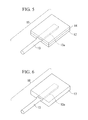
- Figures 1 and 2 show a production method for a molding with a substratum according to the present embodiment.
- a solution preferably containing resin and a solvent is coated onto a sheet-shaped substratum 1 and dried to form a protective layer 2, and a metal-powder-dispersion fluid containing valve action metal powder 3a, binder resin 3b, and a solvent is coated onto the protective layer 2, and dried to form a porous-body-forming layer 3.
- the aforementioned solution when coating the aforementioned solution onto the porous-body-forming layer 3 in order to form the protective layer 2 on the porous-body-forming layer 3, for example, the aforementioned solution might penetrate the porous-body-forming layer depending on the properties of the material, as a result, it may become impossible to obtain the protective layer region having resin as a main component. For this reason, it is typically easier to form previously the protective layer on the substratum.
- the binder resin 3b which forms the porous-body-forming layer 3 and the resin which forms the protective layer 2 are compatible, part or all (preferred, all) of the boundary between the binder resin 3b of the porous-body-forming layer 3 and the resin which forms the protective layer 2 disappears to form a unitary structure.
- resin concentration gradient is formed towards the substratum 1 extending from the porous-body-forming layer 3 to the protective layer 2, which make a unitary structure with the porous-body-forming layer 3, and the resin concentration (concentration of organic compounds) gradually becomes higher in the direction from the second layer 3 to the first layer 2.
- the protective layer 2 and the porous-body-forming layer 3 make a unitary structure in this way, the protective layer 6, which is essentially surface part of the unified porous-body-forming layer 5 and has resin as a main component is formed in the surface of the molding 4. As a result, it is possible to improve the mechanical strength of the molding 4.
- the ratio Catm/Xatm on the substratum 1 side becomes greater than on the surface of the opposite side of molding 4.
- the ratio Catm/Xatm is preferably 1.0 or greater, more preferably 1.2 or greater, and most preferably 1.3 or greater.
- the second embodiment is a production method for a molding in which a protective layer having resin as a main component is formed by forming a coated film on a substratum by using a metal-powder-dispersion fluid containing valve action metal powder, binder resin, and a solvent, and settling down the valve action metal powder in the coated film to form the region where resin is concentrated in the surface of the coated film (i.e., the side opposite the substratum).
- a metal-powder-dispersion fluid including valve action metal powder 3'a and binder resin 3'b is coated on a substratum 1' that is the same substratum 1 shown in Figure 1, to form a film 3', and in this film 3', the valve action metal powder 3'a is settled down onto the substratum 1' side, to form a protective layer 6', having resin as a main component, in a surface layer of the coated film 3'. Under this protective layer 6' there is a porous-body-forming layer 7' containing valve action metal powder as a main component.
- this coated film 3' by coating a metal-powder-dispersion fluid, it is also possible to form that using various other methods such as printing, etc.
- the gradient of the resin concentration is formed within the coated film 3'.
- the concentration gradient of the binder resin 3'b is formed, thereby, a protective layer 6' containing resin as a main component is formed.
- the protective layer 6' which is essentially part of the porous-body-forming layer 5', is formed in the surface layer.
- the viscosity of the metal-powder-dispersion fluid be 5 Pa ⁇ s or less, and more preferably 1 Pa ⁇ s or less.
- the measurement of this viscosity is carried out using a B-type viscometer, and the measured temperature is the temperature during manufacturing operation. If a porous-body-forming layer is formed by a generally used method by using a metal-powder-dispersion fluid which has low viscosity as mentioned, then, it is natural that the valve action metal powder gradually settles down in the coating layer of the metal-powder-dispersion fluid during drying process thereof, and concentration gradients of the resin and valve action metal powder are formed.
- the protective layer 6' can be formed as a result of adjusting the viscosity during coating, therefore, the sort of material used and production process could be more simpler and preferable.
- Materials which can be used as a sheet-shaped substratum include plastic films and sheets comprising, for example, polyethylene film, polypropylene film, polyvinyl chloride film, polyvinylidene chloride film, polyethylene naphthalate film, polyvinyl alcohol film, polyethylene terephthalate (PET) film, polycarbonate film, nylon film, polystyrene film, ethylene vinyl acetate copolymer film, ethylene vinyl copolymer film, and the like; metal sheets such as aluminum; paper or impregnated paper; and composites consisting of the aforementioned various materials.
- PET film polyethylene film
- PET film polycarbonate film
- nylon film polystyrene film
- ethylene vinyl acetate copolymer film ethylene vinyl copolymer film
- metal sheets such as aluminum
- paper or impregnated paper and composites consisting of the aforementioned various materials.
- the most suitable from among these is employed after taking into consideration the adhesive and peeling properties that will result from the resin which
- the thickness of the substratum is not particularly restricted but may be, for example, 5 ⁇ m to 500 ⁇ m, and preferably 10 ⁇ m to 100 ⁇ m.
- the peelable substratum is one in which the film-shaped material itself has peelable properties, or in which there is a peelable layer formed on the surface of the film-shaped material.
- the surface on the substratum side of the molding has peelable properties with respect to the substratum, it is possible to smoothly carry out processing without using the peelable substratum.
- a layer having acrylic resin or polyvinyl acetal resin as a main component is formed as the first layer coated on the substratum, thereby making it possible to provide excellent peelablity between the first layer and the substratum.
- resins employed in the protective layer will depend on such factors as the method of production, from the perspective of their sepatating properties with PET, resins such as polyvinyl alcohol resin, polyvinyl acetal resin, butyral resin, or acrylic resin are preferably employed. Thus, resin including one or more selected from this group is preferred. In these resins, acrylic resin is particularly desirable from the perspective of decreasing residual carbon.
- a protective layer region is formed by binder resin for the valve action metal powder.
- resin disclosed above it is desirable to employ resin disclosed above as the binder resin.
- acrylic resin in particular tends to attain complete decomposition combustion when sintered in the presence of a metal powder, and easily forms a porous metal sintered body having a low residual carbon.
- the adhesive strength varies depending on various conditions such as the type of resin forming each layer (resin compatibility), coating speed, and so forth, it is preferable to carry out testing under actual production conditions and evaluating, and select that which satisfies the desirable properties.
- the first layer and the second layer form a unitary structure, and delamination between the layers does not occur, so this is preferable.
- the degree of which a solvent in a paint which is employed in the formation of the porous-body-forming layer dissolve the resin in the protective layer having resin as a main component is high, there is a possibility that the thickness of the protective layer containing resin as a main component will itself become thinner.
- the resin employed contains a component with a molecular weight of 250,000 or more, and more preferably that the aforementioned component with a molecular weight of 250,000 or more be included in the amount of 30% by weight or more of the total resin.
- the protective layer having resin as a main component can be formed on the sheet-shaped substratum 1 using a variety of methods such as an example shown in Figure 1.
- roller coating methods may be cited as examples of coating methods, including, specifically, air doctor coating, blade coating, rod coating, extrusion coating, air knife coating, squeegee coating, impregnation coating, reverse roll coating, transfer roll coating, gravure coating, kiss coating, cast coating, and spray coating.
- the thickness is not particularly restricted, however, provided it is within a range in which the molding maintains its shape without being destroyed at least during the time period until sintering is initiated.
- a range of 1 ⁇ m to 20 ⁇ m is preferred, and within this range, there is not a large increase in the total amount of resin in the molding, and the amount of residual carbon after sintering does not increasing greatly.
- the range of 1 ⁇ m to 10 ⁇ m is preferred because this does not have much influence to the amount of residual carbon left after sintering, and the strength of the coating can be maintained to a suitable extent.
- the metal-powder-dispersion fluid that is used to form the porous-body-forming layer can be produced by mixing and dispersing valve action metal powder, binder, and a solvent, as well as additive agents as necessary.
- valve action metals as tantalum, aluminum, niobium, titanium, and the like can be used as the valve action metal powder.
- tantalum and niobium are optimal, with the employment of tantalum being particularly preferably.
- the tantalum metal preferably has a purity of 99.5% or greater, with an average primary particle diameter in the range of 0.01 to 5.0 ⁇ m being preferred, and an average primary particle diameter in the range of 0.01 to 2.0 ⁇ m being particularly preferred.
- Solvent-soluble binder resin may be employed as the binder resin.
- suitable binder resins include polyvinyl alcohol resin, polyvinyl acetal resin, butyral resin, phenol resin, acrylic resin, urea resin, vinyl acetate emulsion, polyurethane resin, polyvinyl acetate resin, epoxy resin, melamine resin, alkyd resin, nitrocellulose resin, natural resins, and the like. These resins may be used alone or in combinations of two or more.
- polyvinyl alcohol resin polyvinyl acetal resin, butyral resin, and acrylic resin are suitably employed among the resins cited above.
- acrylic resin is preferred since it is almost entirely decomposed during binder processing in a vacuum so that there is little residual carbon, and it is thus possible to prevent an increase in leakage current from the electrolytic capacitor when making an electrolytic capacitor anode element from the molding.
- the glass transition point of the aforementioned resin be 50°C or less, and more preferably below room temperature. Since when the glass transition point is 50°C or less, it is possible to provide flexibility to the porous-body-forming layer 3 shown in Figures 1 and 2, thereby the molding is not readily destroyed and handling thereof is improved, it is preferable that the glass transition point is 50°C or less.
- the protective layer having resin as a main component it is likewise preferable to select the binder resin so as to satisfy the adhesive strength relationship.
- the amount of the binder resin employed is preferably in the range of 0.01 to 30 parts by weight, and more preferably 0.01 to 15 parts by weight, per 100 parts by weight.
- solvents examples include water, or alcohols such as methanol, 2-propanol (isopropyl alcohol), and diethylene glycol; cellosolves such as methyl cellosolve; ketones such as acetone, methylethylketone, and isophorone; amides such as N,N-dimethylformamide; esters such as ethyl acetate; ethers such as dioxane; chlorinated solvents such as methyl chloride; aromatic hydrocarbons such as toluene and xylene; and the like. These solvents may be used alone or in combinations of two or more.
- alcohols such as methanol, 2-propanol (isopropyl alcohol), and diethylene glycol
- cellosolves such as methyl cellosolve
- ketones such as acetone, methylethylketone, and isophorone
- amides such as N,N-dimethylformamide
- esters such as ethyl a
- the amount of the solvent is set to a degree such the process of coating the metal-powder-dispersion fluid can be carried out smoothly.
- various types of suitable additives can be mixed in the metal-powder-dispersion fluid employed, to provide suitable properties for coating or printing the metal-powder-dispersion fluid to the substratum surface, with the purpose of stably maintaining the metal powder dispersion or flow properties.
- suitable additives include dispersing agents such as phthalic acid esters, phosphoric esters, and fatty acid esters; plasticizers such as glycols; low boiling point alcohols; defoaming agents such as silicon systems and non-silicon systems; silane coupling agents; titanium coupling agents; and dispersing agents such as SOLSPERSE and quaternary ammonium salts, and these may be suitably used as necessary.
- a fatty acid ester having a melting point of 30°C or less it is possible to improve the workability of the molding that is formed from the metal-powder-dispersion fluid, so that damage or defects to portions of the molding during manufacturing become less likely to occur.
- the amount of these additive agents employed is, for example, in the case of tantalum, preferably in the range of 0.01 to 5.0 parts by weight with respect to 100 parts by weight of the tantalum metal powder.
- valve action metal powder, solvent, solvent-soluble binder resin, and additives to be mixed in as needed are added all at once, or respectively in sequence, and these are then dispersed using various kneading and dispersing instruments, to obtain the metal-powder-dispersion fluid.
- Such machines may be employed as an agitator; roll kneaders such as double or triple roll kneaders; blade kneaders such as vertical kneaders, pressure kneaders, and planetary mixers; dispersing machines such as ball-type rotating mills, sand mills, and grinding machines; ultrasonic dispersers; nanomizers, and so forth.
- an example may be cited of 0.01 to 30 parts by weight, and preferably 0.01 to 15 parts by weight, of binder, 5 to 160 parts by weight of solvent, and 0 to 5 parts by weight of additive, with respect to 100 parts by weight tantalum metal powder.
- the viscosity of the dispersion fluid of the valve action metal powder is 1 to 1000 Pa ⁇ s, and preferably 5 to 100 Pa ⁇ s.
- the viscosity of the dispersion fluid of the valve action metal powder be 5 Pa ⁇ s or less, and more preferably 1 Pa ⁇ s or less.
- a B-type viscosimeter was used as the method for measuring viscosity, and the measured temperature is the temperature during operations.
- the dispersion fluid of the valve action metal powder obtained in this way is coated on the substratum in accordance with the production method employed.
- the aforementioned metal-powder-dispersion fluid is coated on the protective layer 2 and dried, to obtain the porous-body-forming layer 3.
- the molding 4 including the porous-body-forming layer 3 and the protective layer 2 having resin as a main component is obtained.
- the thickness of the molding 4 can be optimally set. In the case in which forming a porous anode for an electrolytic capacitor using a sintered body, it is possible to optimally set the thickness of the molding based on the desired capacitance that is required for the electrolytic capacitor, and the thickness of the coating of the dispersion fluid of the metal powder before drying (wet thickness) can be thinned to a range of several ⁇ m to 300 ⁇ m.
- the porous-body-forming layer have a dry thickness of 0.5 mm or less.
- the dry thickness is preferably 0.4 mm or less, more preferably 0.3 to 0.05 mm, and most preferably 0.2 to 0.05 mm.
- the molding 4 shown in Figure 1 preferably with the sheet-shaped substratum 1a is slit to a predetermined width.
- slitting method including for example, a laser cutter method, a shear cutter method employing a shearing effect that moves between a knife and a roller, and the like.
- Shear cutters have good cutter accuracy, and are also good for cutting the thick material.
- a rotary cutter having a plurality of blades can also be employed to make a slit.
- the coated material After coating the dispersion fluid of a metal in stripe state on a first layer 2 shown in Figure 1, drying and then cutting along the coated shape, the coated material can be wound into a reel.
- Slitting can be carried out according to the same methods as described above.
- the molding obtained in this manner is uniformly formed on the substratum, and the film thickness distribution is narrow, and there is superior flexibility and bendability. As a result, the molding can be easily wound into the reel with the sheet-shaped substratum without occurring positional deviations.
- the molding for a sintered body that is wound into a reel after slitting in this way offers superior easiness for storage and transportation.
- An electrolytic capacitor anode element can be made by using the molding of the present invention formed by the method described above. The concrete method will be described below.
- electrolytic capacitor anode element employing the molding of the present invention can be made as described below.
- the molding is separated from the substratum, and cut to a prescribed length, thereafter, as shown in Figure 5, a lead wire, preferably a flat component 13a of a flat lead wire 13, is placed on thereof, and another molding 14 is stacked on them, suitable pressure processing is carried out as necessary, and the two moldings 12,14 and the flat lead wire 13 are closely adhered together, thereby, a molding element 15 for an electrolytic capacitor anode element (hereinafter referred to simply as "molding element 15”) is formed.
- the molding of the present invention has a protective layer having resin as a main component for protecting the porous-body-forming layer, the molding is not damaged nor does it fall from the substratum, during slitting or during winding after slitting, moreover, the molding is not readily damaged during pressure processing to sandwich a lead wire between moldings.
- the aforementioned flat lead wire comprises valve action metal such as tantalum, and at least the portion that is embedded in the anode element, or the entire part, is made to be flat.
- This flat lead wire can be formed by flattening at least a portion of a tantalum wire by using pressure molding.
- the thickness and width of the flat portion of the flat lead wire can be optimally set on the grounds that the thickness of the anode element to be produced, the strength of the lead wire, and so forth, and it is preferable to flatten this portion to a thickness, the range of which is 5 to 70% of that of the molding.
- the molding element 15 for an electrolytic capacitor anode element is dried as necessary, and the organic material (binder) is removed by a heat treatment at approximately 300 to 600°C in a vacuum, after that, a high-temperature heat treatment (sintering) at around 1200 to 1600°C is further carried out for approximately 10 to 30 minutes, thereby the tantalum metal particles are fused together, and the tantalum metal powder and the lead wire, preferably flat lead wire 13, are fused.
- a tantalum electrolytic capacitor anode element 18 is produced, having a structure in which the lead wire 13, preferably the flat component 13a of the flat lead wire, is embedded inside a thin, rectangular tantalum porous sintered body 17, as shown in Figure 6.
- Thus-obtained tantalum electrolytic capacitor anode element 18 has an arrangement such that the tantalum porous sintered body and the lead wire 13 are strongly adhered together.
- the anode element 18 In order to produce a tantalum electrolytic capacitor using a tantalum electrolytic capacitor anode element 18, the anode element 18 is immersed in an electrolyte bath, a prescribed direct current voltage is applied to the anode element 18 to carry out a chemical conversion treatment, thereby a tantalum oxide dielectric layer is formed in the surface of the anode element 18.
- a solid state electrolyte such as a manganese dioxide layer or a functional polymer layer is formed on the oxide film.
- a carbon (graphite) layer and a silver paste layer are formed, and as shown in Figure 7, for example, one end of an anode terminal 32 is connected to the surface of this capacitor element 31 by solder 34, at the same time, the end portion of a flat lead wire 13 is connected to an anode terminal 33 by spot welding (joining point is indicated by numeric symbol 35), after which resin sheathing 36 is executed by, for example, resin molding or by soaking in a resin solution, resulting in forming a tantalum electrolytic capacitor 30.
- the production method of the present invention can be also applied to the production of a laminated electrolytic capacitor.
- This type of laminated electrolytic capacitor can be formed by laminating an extremely thin electrolytic capacitor produced according to the production method of the present invention and then joining them.
- a toluene solution including 20% by weight of solid component of acrylic resin "IB-30” (manufactured by FUJIKURA KASEI Co., Ltd., component substance: isobutylmethacrylate, weight average molecular weight: 200,000 to 300,000) was developed over a PET film 50 ⁇ m thick using a #16 wire bar to provide a protective layer having a thickness of 4 ⁇ m.
- the tantalum-metal-powder-dispersion fluid (A) was developed over the above first layer using a 450 ⁇ m deep applicator, to obtain a dried coated film of the tantalum-metal-powder-dispersion fluid (A) (porous-body-forming layer).
- the binder resin for the porous-body-forming layer and the resin employed in the protective layer include compatible resins, a cross-section is obtained of an electrolytic capacitor anode element in which a portion of the boundary between the protective layer and the porous-body-forming layer has disappeared, and a protective layer contains high concentration of resin.
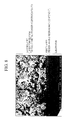
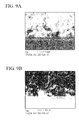
- mapping date for the carbon atoms and the tantalum atoms is shown respectively in Figures 9A and 9B.
- the mapping data is obtained by measuring K line of carbon and L line of tantalum using SEM-EDS.
- the detector employed was manufactured by EDX, and the time constant and other measured conditions were carried out using standard measurement conditions of EDX.
- a molding for an electrolytic capacitor anode element was prepared in the same manner as in Example 1, with the exception that an acrylic resin having the same structural composition as "IB-30” with a weight average molecular weight of 230,000 to 290,000 in the amount of 75% by weight, and an acrylic resin having the same component substances as "IB-30” with a weight average molecular weight of 70,000 to 90,000 in the amount of 25% by weight were employed as the acrylic resin employed in the first layer, and the Catm/Taatm in the surfaces of the molding on the substratum side and on the opposite side was measured in the same way as in Example 1, and found to be 1.25 to 1.41 and 0.64 to 0.74, respectively.
- a molding for an electrolytic capacitor anode element was prepared in the same manner as in Example 1, with the exception that an acrylic resin having the same component substances as "IB-30” with a weight average molecular weight of 230,000 to 290,000 in the amount of 50% by weight, and an acrylic resin having the same structural composition as "IB-30” with a weight average molecular weight of 70,000 to 90,000 in the amount of 50% by weight were employed as the acrylic resin employed in the first layer, and the Catm/Taatm in the surfaces of the molding on the substratum side and on the opposite side was measured in the same way as in Example 1, and found to be 1.08 to 1.28 and 0.37 to 0.42, respectively.
- the tantalum-metal-powder-dispersion fluid (B) was spread with using an applicator having a depth of 450 ⁇ m on a PET film50 ⁇ m thick as a substratum, and dried to obtain a dried layer of the tantalum-metal-powder-dispersion fluid (B) having a thickness of 200 ⁇ m.
- the tantalum metal powder in the porous-body-forming layer is settled down to the PET film side, and the concentration of the binder resin becomes higher in the direction to the surface of the porous-body-forming layer, so that a cross-section of the molding for the electrolytic capacitor anode element was obtained in which a protective layer having high concentration of resin as a main component was formed near the surface.
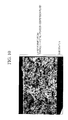
- mapping of these carbon atoms is shown in Figure 11.
- the mapping data was obtained using the same measurement conditions as in Example 1.
- the ratio of the number of atoms Catm/Taatm for the amount of tantalum atoms present and the amount of carbon atoms present on the substratum side surface of the molding for the electrolytic capacitor anode element, and the ratio of the number of atoms Catm/Taatm on the opposite surface (the side where the protective layer having resin as a main component is formed) was measured, and found to be 0.46 to 0.69 and 1.29 to 3.50, respectively.
- a dried layer (porous-body-forming layer) made of tantalum-metal-powder-dispersion fluid (A) having a thickness of 200 ⁇ m was obtained in the same manner as Example 1, with the exception that a protective layer having resin as a main component was not formed.
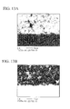
- mapping data of these carbon atoms and tantalum atoms are shown respectively in Figure 13A and 13B. Here, mapping data was obtained using the same measurement conditions as in Example 1.
- the ratio of the number of atoms Catm/Taatm for the amount of tantalum atoms present and the amount of carbon atoms present on the substratum side surface of the molding for the electrolytic capacitor anode element, and the ratio of the number of atoms Catm/Taatm on the opposite surface was measured. Each was found to be 0.60 to 0.75.
- the molding was slit to a width of 3.6 mm with the PET (substratum), and the molding with the substratum was wound into a reel.
- the molding wound into a reel was separated from the PET, spread out in a straight line, and then chipped by cutting into 3.6 x 4.4 mm sizes.
- the flat portion of a flat lead wire formed by applying pressure to flatten the tip of a 0.2 mm diameter lead wire was sandwiched between the moldings and stacked, to form a molding element 15 for an electrolytic capacitor anode element shown in Figure 5.
- the molding element 15 for an electrolytic capacitor anode element was heated to 350°C in a vacuum at 6.6 x 10 -3 Pa (5x10 -5 torr) and subjected to a heat treatment for 90 minutes to decompose and remove the organic material (binder).
- a sintering treatment was then carried out at 1300°C for 20 minutes, as a result, a tantalum electrolytic capacitor anode element 18 was obtained having a structure as shown in Figure 6, in which the flat portion 13a of the flat lead wire 13 was embedded inside a thin rectangular tantalum porous sintered body 17.
- the protective layer having resin as a main component because mechanical strength of the molding for an electrolytic capacitor anode element was provided by the protective layer having resin as a main component in this way, the shape of the reel or the chip of molding was maintained throughout the processing steps, i.e., throughout slitting, separating the substratum, spreading in a straight line, cutting, sandwiching and pressurizing the lead wire, etc., even under impacts during bending, cutting, etc. or under pressure application when forming a unitary structure with the lead wire. So workability of the molding for electrolytic capacitor anode element was extremely good. Further, since the molding element for an electrolytic capacitor anode element could be continuously formed from a reeled molding, the production efficiency was extremely good for the molding element for an electrolytic capacitor anode element and the electrolytic capacitor anode element.
- the present invention provides mechanical strength to the molding through the provision of a protective layer having resin as a main component, as a result, even when the amount of binder resin included in the porous-body-forming layer is reduced so that the amount of residual carbon after sintering can be decreased, the present invention enables provision of a molding having excellent workability.
- the protective layer having resin as a main component that is for protecting the valve action metal may be disposed in the surface of the molding, it is easy to remove the carbon during sintering.
- the molding present invention
Landscapes
- Engineering & Computer Science (AREA)
- Power Engineering (AREA)
- Microelectronics & Electronic Packaging (AREA)
- Chemical & Material Sciences (AREA)
- Materials Engineering (AREA)
- Powder Metallurgy (AREA)
Abstract
The present invention provides a molding having excellent workability and a
production method therefore. In addition, the present invention provides a molding with
which a capacitor element having excellent electric properties can be obtained, and which
has excellent workability that can be used to make a porous anode element for an
electrolytic capacitor. The molding with a substratum has a sheet-shaped substratum and
a molding which is provided on this sheet-shaped substratum such that the molding can
be separated, in which the molding has a protective layer and a porous-body-forming
layer, the protective layer includes resin as a main component, and the porous-body-forming
layer includes valve action metal powder and binder resin.
Description
The present invention relates to a molding with a substratum which has a molding
comprising valve action metal such as tantalum and binder resin; and to a production
method therefore, and within the aforementioned; to a molding with a substratum for
sintering process and a production method therefore, more particularly, the present
invention relates to a molding with a substratum, in which the molding is employed in
sintering to form a porous sintered body for an electrolytic capacitor anode; and to a
production method therefore.
In a porous body comprising valve action metal such as tantalum, niobium or the
like, a dielectric layer comprising oxide with a controllable thickness can be formed in
the surface of the porous body by using an anodic oxidation, and such porous bodies
have been widely employed as anode elements for electrolytic capacitors by making use
of the wide surface area of the porous body. Particularly as tantalum has high resistance
to heat and corrosion, it has been employed as a sintered body for filament material,
chemical equipment parts, artificial bone and the like, and its use as an electrolytic
capacitor is overwhelming.
Technology in miniaturization of surface-mounted devices have progressed
rapidly in recent years, and technologies for mounting to component boards in electronic
devices such as cellular telephones, personal computers and digital cameras have been
highly integrated. Under this background, various research efforts have also been
conducted in the field of capacitor elements, which are electronic parts, catching up with
the demand for a smaller, thinner, larger capacity product.
Among capacitor elements that are typically employed at the present time, in
particular tantalum electrolytic capacitors have the property of enabling a large capacity
in a small size, and have been greatly researched with the goal of further decreasing size
and thickness.
Examples of materials having the same properties as tantalum metal, i.e., so-called
valve action metals, include various metal materials like aluminum, niobium and
titanium, however, tantalum metal is highly demanded for its heat resistance and forming
capability of a dielectric layer.
As for a method for producing an electrolytic capacitor employing the
aforementioned valve action metal powder such as tantalum for example, typically, the
tantalum is used as an anode metal powder, and the tantalum metal powder and resin
which functions as binder are filled in a metal die, and are subjected to pressure
processing and chipping, to form a molding for anode element.
A component (typically a tantalum lead wire) which becomes the anode terminal
is provided to the molding for an anode element. This lead wire is typically inserted
within the tantalum metal powder set in the metal die, and is fixed in place by pressure
molding of the tantalum metal powder.
An anode element obtained through the above steps then goes through a process
to vaporize and remove the unnecessary resin therein by subjecting the element to high
temperature heating treatment in a vacuum.
Through this process, in which the resin present in the tantalum metal powder is
vaporized and removed and the tantalum metal particles are fused at their points of
contact, a tantalum electrolytic capacitor anode element with a porous body is obtained.
A tantalum electrolytic capacitor anode element obtained in this way is dipped in
a electrolytic bath, a prescribed DC voltage is applied, and a chemical conversion
treatment is carried out, to form a dielectric layer comprising tantalum oxide on the
surface of the tantalum metal powder, thereafter, a solid electrolyte coating of manganese
dioxide or functional polymer coating is formed on the dielectric layer.
Next, after a process of forming a cathode layer using carbon and silver paste is
carried out and resin outer sheathing is provided, to obtain the final tantalum electrolytic
capacitor.
In response to the demands for smaller and thinner electrolytic capacitors,
research has been proceeding to further decrease the size and thickness of the dimensions
of the capacitor. The capacitor is made thinner, for example, so as to be embedded in the
board=or to be laminated, so that it is possible to realize low Equivalent Series Resistance
(ESR) and to improve high frequency properties. However, in conventional methods
using a die, it is difficult to make a thin-type electrolytic capacitor anode element with a
thickness of 0.5 mm or less efficiently, and moreover, it has also been difficult to form a
large type electrolytic capacitor anode element even if the thickness is around 1 mm.
As for a method for making the aforementioned anode element thinner, Japanese
Patent Application, First Publication No. Sho. 56-83022 discloses a method for
producing an electrolytic capacitor anode element in which valve action metal powder,
binder including a thermoplastic resin, and an organic solvent are mixed together to form
a paste; and by using the paste, a sheet is formed (i.e., a molding in the form of a thin
film), and lead wire is connected to the sheet; and a debinder treatment is carried out, and
sintering is performed to obtain the desired product.
However, when forming a sheet by using a paste comprising a mixture of valve
action metal powder, binder resin, and an organic solvent as described above, there were
the following problems to be solved.
In particular, when an electrolytic capacitor anode element is made by sintering a
molding for this purpose, it is preferable that the quantity of binder resin be limited to as
small as possible in order to ensure good capacitor properties such as low residual carbon
and small leakage current, however, the reduction of the blending amount of binder resin
causes to the decrease of the mechanical strength of the sheet (molding) and to difficult
handling. In some cases, yield may decline due to, for example, damage to a portion of
the molding during the separation of molding from the substratum or after the separation
of molding from the substratum, in the production process.
In other words, when the blending amount of the valve action metal powder is
increased, the adhesive effect provided by the binder resin decreases, and in particular,
when the element is made thinner, then the molding is more fragile, accordingly, the
binder resin is required to be present at a specific proportional amount or greater.
On the other hand, if the blended binder resin is sufficient to ensure strength, the
residual carbon increases as described above, and as a result, causes such problems as
degradation in the electric properties of the capacitor anode element.
The present invention was conceived in view of the above-described
circumstances and has as its objective the provision of a molding with a substratum,
which has a molding having excellent workability, and a production method therefore,
and particularly, the provision of a molding with a substratum for sintering process
and a production method therefore. Moreover, the present invention aims to provide a
molding with a substratum for sintering process having a molding with which a capacitor
anode element with excellent electric properties can be obtained, and which has excellent
workability that can be used to make a porous anode element for an electrolytic capacitor.
In order to solve the above-described problems, the molding with a substratum of
the present invention has a sheet-shaped substratum and a molding that is provided on the
sheet-shaped substratum such that the molding can be separated, and the molding has a
protective layer and a porous-body-forming layer, in which the protective layer contains
resin as a main component and the porous-body-forming layer contains valve action
metal powder and binder resin.
The production method for producing the molding with a substratum of the
present invention includes a step for forming a protective layer having resin as a main
component on a sheet-shaped substratum, and a step for forming a porous-body-forming
layer with valve action metal powder and binder resin on the protective layer, wherein
the adhesive strength between the protective layer and the porous-body-forming layer is
made to be greater than the adhesive strength between the sheet-shaped substratum and
the protective layer.
The other production method for producing the molding with a substratum of the
present invention includes a step for forming a coated layer on a sheet-shaped substratum
by coating a paint for forming porous body including valve action metal powder,
binder resin, and a solvent, and a step for forming a protective layer with resin as a main
component in the surface of the coated layer caused by the settling of the valve action
metal powder in the coated layer.
The present invention further provides a molding for a capacitor anode element
that is provided with valve action metal layer comprising valve action metal powder and
binder resin, and that has a sheet-like region for protecting the valve action metal layer,
containing resin as a main component on at least one surface of the molding.
Since the molding of the present invention has a sheet-shaped region (protective
layer) having resin as a main component in order to protect the porous molding layer
having valve action metal powder and binder resin, this region functions as the
reinforcement of the molding, making it possible to prevent the molding from crumbling
and the like.
Since this layer-shaped region (protective layer) having resin as a main
component for protecting the porous-body-forming layer may be provided to a small
portion of the surface region of the molding, it is possible to decrease the residual carbon
in the sintered body, and as a result, when this sintered body is then employed as a
porous anode for an electrolytic capacitor, excellent electrical properties can be ensured
for the electrolytic capacitor anode element.
The production method for a molding with a substratum of the present invention
is hereinafter explained by using a number of embodiments as examples.
Here, in the specification, the term "molding" shall be used to refer to a variety of
forms prior to the sintering step, including both a molding with a substratum and a
molding without a substratum. In the specification, the term shall be used without further
modification when there is no doubt about the form, however, when it is desirable to
make clear the relationship with the substratum, then the terms "with a substratum" or
"without a substratum" will be added.
The term "molding element" refers to an arrangement in which a lead wire is
attached to the aforementioned "molding without a substratum," and indicates the
embodiment of the molding before sintering, when making the electrolytic capacitor
anode element.
The term "anode element" indicates the conformation after sintering of the
"molding element."
In the present specification, the "protective layer having resin as a main
component for protecting the porous-body-forming layer" may be one that includes
essentially no valve action metal powder, or may be one that includes valve action metal
powder, provided that the resin concentration is enough to permit to protect the porous-body-forming
layer.
Since the "layer having resin as a main component" depends on the properties of
the employed material and on the conformation of the protective layer which relies on the
method of production therefore, an all-inclusive definition of the "layer having resin as a
main component" cannot be provided, however, for example, when tantalum is employed
for the valve action metal, the resin concentration in the area of highest concentration
thereof is 10% by weight or greater, and preferably 15% by weight or greater, it is
preferable to set this concentration such that the function of protecting the porous-body-forming
layer is sufficiently performed.
On the contrary, with regard to the porous-body-forming layer, having valve
action metal powder as a main component, which becomes a porous body after sintering,
as is determined later by the preferred blending ratios, the resin concentration is
preferably 9% by weight or less, and more preferably 5% by weight or less, in the case
where the valve action metal is Ta, for example.
In addition, the protective layer having resin as a main component may be present
as an independent layer separate from the porous-body-forming layer, or may be
separately formed and then laminated onto the porous-body-forming layer.
Alternatively, this protective layer may be a layer with a high resin concentration that is
formed by using resin concentration gradient in a surface layer of the porous-body-forming
layer (for example, a layer which is formed in a unitary manner with the porous-body-forming
layer, and which is present essentially as one part of the porous-body-forming
layer, forming the surface of the porous-body-forming layer).
In other words, the protective layer having resin as a main component preferably
can be formed as the surface layer of the porous-body-forming layer, or be formed as an
independent layer (protective layer) which is adjacent to the porous-body-forming layer.
Here, when forming the protective layer having resin as a main component as the
aforementioned surface layer of the porous-body-forming layer, the paint for forming the
porous-body-forming layer can be used, and resin concentration gradient can be formed
in the porous-body-forming layer, as explained below. Further, by using the paint for the
porous-body-forming layer and a different paint having a higher resin concentration
which is compatible with the paint for the porous-body-forming layer, and by forming a
coated film with a two-layer structure (laminated body), and by making a mutually
unitary structure with the layers formed from these two paints as a result, it is possible to
make a protective layer having resin as a main component in which resin concentration
gradient is formed in the unified layers.
Here, though the protective layer having resin as a main component may be
formed in the surface layer of the molding, and may be formed in one or both surfaces of
the molding, when employing the sintered body as a porous anode for an
electrolytic capacitor, it is preferable to provide the protective layer in only one side of
the molding for the purpose of reducing the residual carbon.
The first embodiment is a production method for a molding in which a first layer
being made of paint for a protective layer having resin as a main component, and a
second layer being made of paint for a porous-body-forming layer, are formed on a
substratum in this order, wherein the adhesive strength between the first layer and the
second layer is made to be greater than the adhesive strength between the first layer and
the substratum.
Figures 1 and 2 show a production method for a molding with a substratum
according to the present embodiment.
First, a solution preferably containing resin and a solvent is coated onto a sheet-shaped
substratum 1 and dried to form a protective layer 2, and a metal-powder-dispersion
fluid containing valve action metal powder 3a, binder resin 3b, and a solvent
is coated onto the protective layer 2, and dried to form a porous-body-forming layer 3.
Here, in addition to coating, it is also acceptable to employ a variety of methods,
such as printing, to form the protective layer 2 or the porous-body-forming layer 3 by
using the aforementioned solution or metal-powder-dispersion fluid.
In addition, opposite to the case shown in Figures 1 and 2, it is also possible to
form previously the porous-body-forming layer 3 on the substratum 1.by using the metal-powder-dispersion
fluid.
However, in this case, when coating the aforementioned solution onto the porous-body-forming
layer 3 in order to form the protective layer 2 on the porous-body-forming
layer 3, for example, the aforementioned solution might penetrate the porous-body-forming
layer depending on the properties of the material, as a result, it may become
impossible to obtain the protective layer region having resin as a main component. For
this reason, it is typically easier to form previously the protective layer on the substratum.
In this way, opposite to the case shown in Figures 1 and 2, when first providing
the porous-body-forming layer 3 on the substratum 1, and then forming the protective
layer 2 on this porous-body-forming layer 3, it is preferable to provide a high viscosity to
the solution containing the resin and the solvent for forming the protective layer 2, in
order to prevent the solution from penetrating too much into the porous-body-forming
layer 3 when coating the solution on the porous-body-forming layer 3.
Alternatively, it is also acceptable to form a separate protective layer on the other
substratum, and then to laminate this layer on the porous-body-forming layer 3 by using
a transferring method.
Next, when separating from the substratum 1, since the adhesive strength between
the protective layer 2 and the porous-body-forming layer 3 is greater than the adhesive
strength between the substratum 1 and the protective layer 2, as shown in Figure 2, the
protective layer 2 is pulled off from the substratum 1 keeping a unitary structure with the
porous-body-forming layer 3, thereby a molding 4 is obtained in which the protective
layer 2 having resin as a main component is provided on one surface of the porous-body-forming
layer 3, i.e., on the surface of the molding 4.
Further, in the case that the binder resin 3b which forms the porous-body-forming
layer 3 and the resin which forms the protective layer 2 are compatible, part or all
(preferred, all) of the boundary between the binder resin 3b of the porous-body-forming
layer 3 and the resin which forms the protective layer 2 disappears to form a unitary
structure. As a result, as shown in Figure 3, resin concentration gradient is formed
towards the substratum 1 extending from the porous-body-forming layer 3 to the
protective layer 2, which make a unitary structure with the porous-body-forming layer
3, and the resin concentration (concentration of organic compounds) gradually becomes
higher in the direction from the second layer 3 to the first layer 2.
By having the protective layer 2 and the porous-body-forming layer 3 make a
unitary structure in this way, the protective layer 6, which is essentially surface part of
the unified porous-body-forming layer 5 and has resin as a main component is formed in
the surface of the molding 4. As a result, it is possible to improve the mechanical
strength of the molding 4.
As shown in Figures 2 and 3, whether the separation occur at the boundary
surface of the substratum 1 and the protective layer 2 (or 6) can be determined by
measuring the ratio Catm/Xatm at the separating surface of molding 4, where Catm
denotes the amount of carbon atoms present and Xatm denotes the amount of valve
action metal atoms X present, as the count ratio of the electric signal pulse corresponding
to their respective characteristic x-rays, by applying micro-analytical methods such as
electron probe microanalysis (EPMA) or SEM-EDS.
In other words, when the protective layer 2 or 6 is formed, since the protective
layer 2 or 6 comprises an organic compound having resin as a main component, the ratio
Catm/Xatm on the substratum 1 side becomes greater than on the surface of the opposite
side of molding 4.
In the protective layer having resin as a main component, the ratio Catm/Xatm is
preferably 1.0 or greater, more preferably 1.2 or greater, and most preferably 1.3 or
greater.
In addition, since it is possible to maintain the form of molding 4 (porous-body-forming
layer 5 or porous-body-forming layer 3 and protective layer 2) in the subsequent
processing steps to the sintering step by forming the protective layer 2 or 6, so that
workability can be improved, it is possible to confirm the presence of the protective layer
2 or 6 by the improvement of aptitude for processing in testing of production workability.
The second embodiment is a production method for a molding in which a
protective layer having resin as a main component is formed by forming a coated film on
a substratum by using a metal-powder-dispersion fluid containing valve action metal
powder, binder resin, and a solvent, and settling down the valve action metal powder in
the coated film to form the region where resin is concentrated in the surface of the coated
film (i.e., the side opposite the substratum).
For example, as shown in Figure 4, a metal-powder-dispersion fluid including
valve action metal powder 3'a and binder resin 3'b is coated on a substratum 1' that is
the same substratum 1 shown in Figure 1, to form a film 3', and in this film 3', the valve
action metal powder 3'a is settled down onto the substratum 1' side, to form a protective
layer 6', having resin as a main component, in a surface layer of the coated film 3'.
Under this protective layer 6' there is a porous-body-forming layer 7' containing valve
action metal powder as a main component.
Here, in addition to forming this coated film 3' by coating a metal-powder-dispersion
fluid, it is also possible to form that using various other methods such as
printing, etc.
In this case, as in the case shown in Figure 3, the gradient of the resin
concentration is formed within the coated film 3'. In this case, the concentration gradient
of the binder resin 3'b is formed, thereby, a protective layer 6' containing resin as a main
component is formed. In other words, the protective layer 6', which is essentially part
of the porous-body-forming layer 5', is formed in the surface layer.
For this reason, even if the substratum 1' is ripped away, a suitable amount of
strength is provided by the effect of the protective layer 6' which is formed in the surface
layer of the porous-body-forming layer 5', as a result, the effect of improved workability
of the moldig4' is obtained.
In order to form the protective layer 6' by settling down the valve action metal in
this way, it is preferable that the viscosity of the metal-powder-dispersion fluid be 5 Pa·s
or less, and more preferably 1 Pa·s or less. The measurement of this viscosity is carried
out using a B-type viscometer, and the measured temperature is the temperature during
manufacturing operation. If a porous-body-forming layer is formed by a generally used
method by using a metal-powder-dispersion fluid which has low viscosity as mentioned,
then, it is natural that the valve action metal powder gradually settles down in the coating
layer of the metal-powder-dispersion fluid during drying process thereof, and
concentration gradients of the resin and valve action metal powder are formed.
In this present embodiment, only with the substratum 1' and a paint for the
porous-body-forming layer 5', the protective layer 6' can be formed as a result of
adjusting the viscosity during coating, therefore, the sort of material used and production
process could be more simpler and preferable.
In addition, in either the first and the second embodiments, as shown in Figure 2,
prior to separating the substratum 1 in manufacturing process, it is preferable to slit the
molding 4 with the substratum 1 shown in Figure 1 to a predetermined width, since this
provides a remarkable improvement in the continuous workability in continuous
manufacturing of the molding for an electrolytic capacitor anode element. In addition,
this is also preferable for the perspective that there is no useless part, the so-called
"lug", generated during the punching process. Further, when coating a metal-powder-dispersion
fluid on the first layer 2, it is also possible to coat the fluid in a stripe pattern
and dry, and then cut along the coated shape.
The various components employed in the production of a molding with a
substratum described in the summary above will now be explained in detail, along with
the production steps.
Materials which can be used as a sheet-shaped substratum include plastic films
and sheets comprising, for example, polyethylene film, polypropylene film, polyvinyl
chloride film, polyvinylidene chloride film, polyethylene naphthalate film, polyvinyl
alcohol film, polyethylene terephthalate (PET) film, polycarbonate film, nylon film,
polystyrene film, ethylene vinyl acetate copolymer film, ethylene vinyl copolymer film,
and the like; metal sheets such as aluminum; paper or impregnated paper; and composites
consisting of the aforementioned various materials. The most suitable from among these
is employed after taking into consideration the adhesive and peeling properties that will
result from the resin which makes up the layer that is formed on the substratum.
Materials other than the aforementioned may be used without particular restriction, so
long as they are equipped with the required strength and flexibility, more preferably,
peeling properties. From the perspective of strength, solvent resistance, and price, PET
film is typically employed.
The thickness of the substratum is not particularly restricted but may be, for
example, 5 µm to 500 µm, and preferably 10 µm to 100 µm.
It is acceptable to use a peelable substratum as the aforementioned substratum
so that the boundary between the substratum and the molding can be easily separated.
The peelable substratum is one in which the film-shaped material itself has peelable
properties, or in which there is a peelable layer formed on the surface of the film-shaped
material. Here, when the surface on the substratum side of the molding has peelable
properties with respect to the substratum, it is possible to smoothly carry out processing
without using the peelable substratum.
In the case where, for example, PET film is employed as the substratum as
described below, a layer having acrylic resin or polyvinyl acetal resin as a main
component is formed as the first layer coated on the substratum, thereby making it
possible to provide excellent peelablity between the first layer and the substratum.
Although selection of the resin employed in the protective layer will depend on
such factors as the method of production, from the perspective of their sepatating
properties with PET, resins such as polyvinyl alcohol resin, polyvinyl acetal resin,
butyral resin, or acrylic resin are preferably employed. Thus, resin including one or more
selected from this group is preferred. In these resins, acrylic resin is particularly
desirable from the perspective of decreasing residual carbon.
Here, as shown in Figure 4, when forming a protective layer having resin as a
main component by using a metal-powder-dispersion fluid and settling down valve
action metal powder, a protective layer region is formed by binder resin for the valve
action metal powder. In this case, it is desirable to employ resin disclosed above as the
binder resin.
In these resins, acrylic resin in particular tends to attain complete
decomposition combustion when sintered in the presence of a metal powder, and easily
forms a porous metal sintered body having a low residual carbon.
Further, as described above, when providing a protective layer as the first layer
and a porous-body-forming layer as the second layer on the sheet-shaped substratum in
this order, and making the adhesive strength between the protective layer and the porous-body-forming
layer greater than the adhesive strength between the sheet-shaped
substratum and the protective layer, it is necessary to set the adhesive strength so that the
aforementioned conditions are satisfied.
Since the adhesive strength varies depending on various conditions such as the
type of resin forming each layer (resin compatibility), coating speed, and so forth, it is
preferable to carry out testing under actual production conditions and evaluating, and
select that which satisfies the desirable properties.
Although there are no restrictions in particular, when employing PET film as the
substratum, the following types of resin combinations may be cited specifically:
A combination of acrylic resin for the first layer (protective layer), and same type
of acrylic resin as the first layer for the second layer (porous-body-forming layer); or a
combination of polyvinyl acetal resin for the first layer (protective layer), and acrylic
resin for the second layer (porous-body-forming layer).
Here, when the same type of resin is employed for the protective layer and the
porous-body-forming layer, the boundary between the protective layer 2 and the porous-body-forming
layer 3 disappears as shown in Figure 3 due to compatibility, and resin
concentration gradient is formed.
By eliminating the boundary in this way, the first layer and the second layer
form a unitary structure, and delamination between the layers does not occur, so this is
preferable.
However, the degree of which a solvent in a paint which is employed in the
formation of the porous-body-forming layer dissolve the resin in the protective layer
having resin as a main component is high, there is a possibility that the thickness of the
protective layer containing resin as a main component will itself become thinner. For
this reason, it is preferable that the resin employed contains a component with a
molecular weight of 250,000 or more, and more preferably that the aforementioned
component with a molecular weight of 250,000 or more be included in the amount of
30% by weight or more of the total resin.
The protective layer having resin as a main component can be formed on the
sheet-shaped substratum 1 using a variety of methods such as an example shown in
Figure 1.
Conventionally known roller coating methods may be cited as examples of
coating methods, including, specifically, air doctor coating, blade coating, rod coating,
extrusion coating, air knife coating, squeegee coating, impregnation coating, reverse roll
coating, transfer roll coating, gravure coating, kiss coating, cast coating, and spray
coating.
Further, a solution in which the optimal resin has been dissolved in a suitable
concentration can be employed. The same solvents that form the metal-powder-dispersion
fluid described below may be employed for the solvent here.
Since there are various embodiments of the protective layer itself, it is difficult to
clearly prescribe a thickness for the protective layer having resin as a main component,
therefore, the thickness is not particularly restricted, however, provided it is within a
range in which the molding maintains its shape without being destroyed at least during
the time period until sintering is initiated.
For example, a range of 1 µm to 20 µm is preferred, and within this range, there
is not a large increase in the total amount of resin in the molding, and the amount of
residual carbon after sintering does not increasing greatly. Specifically, the range of 1
µm to 10 µm is preferred because this does not have much influence to the amount of
residual carbon left after sintering, and the strength of the coating can be maintained to a
suitable extent.
The metal-powder-dispersion fluid that is used to form the porous-body-forming
layer can be produced by mixing and dispersing valve action metal powder, binder, and a
solvent, as well as additive agents as necessary.
Powders of such valve action metals as tantalum, aluminum, niobium, titanium,
and the like can be used as the valve action metal powder. In these valve action metals,
tantalum and niobium are optimal, with the employment of tantalum being particularly
preferably.
The following explanation will employ tantalum metal powder as the example.
The tantalum metal preferably has a purity of 99.5% or greater, with an average
primary particle diameter in the range of 0.01 to 5.0 µm being preferred, and an average
primary particle diameter in the range of 0.01 to 2.0 µm being particularly preferred.
Solvent-soluble binder resin may be employed as the binder resin. Examples of
suitable binder resins that may be cited include polyvinyl alcohol resin, polyvinyl acetal
resin, butyral resin, phenol resin, acrylic resin, urea resin, vinyl acetate emulsion,
polyurethane resin, polyvinyl acetate resin, epoxy resin, melamine resin, alkyd resin,
nitrocellulose resin, natural resins, and the like. These resins may be used alone or in
combinations of two or more.
As in the case of the protective layer having resin as a main component, polyvinyl
alcohol resin, polyvinyl acetal resin, butyral resin, and acrylic resin are suitably
employed among the resins cited above.
Among these, acrylic resin is preferred since it is almost entirely decomposed
during binder processing in a vacuum so that there is little residual carbon, and it is thus
possible to prevent an increase in leakage current from the electrolytic capacitor when
making an electrolytic capacitor anode element from the molding.
It is preferable that the glass transition point of the aforementioned resin be 50°C
or less, and more preferably below room temperature. Since when the glass transition
point is 50°C or less, it is possible to provide flexibility to the porous-body-forming layer
3 shown in Figures 1 and 2, thereby the molding is not readily destroyed and handling
thereof is improved, it is preferable that the glass transition point is 50°C or less.
Here, as was discussed above in the explanation of the protective layer having
resin as a main component, it is likewise preferable to select the binder resin so as to
satisfy the adhesive strength relationship.
In the case of tantalum metal powder, for example, the amount of the binder
resin employed is preferably in the range of 0.01 to 30 parts by weight, and more
preferably 0.01 to 15 parts by weight, per 100 parts by weight.
In the case in which the amount of binder resin compounded is too large, the
amount of residual carbon after sintering will increase and, for example, when making an
electrolytic capacitor anode element from the molding, there is a risk that such
undesirable circumstances will occur as a deterioration in the capacitor properties.
Examples of solvents which may be cited include water, or alcohols such as
methanol, 2-propanol (isopropyl alcohol), and diethylene glycol; cellosolves such as
methyl cellosolve; ketones such as acetone, methylethylketone, and isophorone; amides
such as N,N-dimethylformamide; esters such as ethyl acetate; ethers such as dioxane;
chlorinated solvents such as methyl chloride; aromatic hydrocarbons such as toluene and
xylene; and the like. These solvents may be used alone or in combinations of two or
more.
The amount of the solvent is set to a degree such the process of coating the metal-powder-dispersion
fluid can be carried out smoothly.
In addition to the aforementioned tantalum metal powder, binder resin, and
solvent, various types of suitable additives can be mixed in the metal-powder-dispersion
fluid employed, to provide suitable properties for coating or printing the metal-powder-dispersion
fluid to the substratum surface, with the purpose of stably maintaining the
metal powder dispersion or flow properties.
Examples of suitable additives include dispersing agents such as phthalic acid
esters, phosphoric esters, and fatty acid esters; plasticizers such as glycols; low boiling
point alcohols; defoaming agents such as silicon systems and non-silicon systems; silane
coupling agents; titanium coupling agents; and dispersing agents such as SOLSPERSE
and quaternary ammonium salts, and these may be suitably used as necessary. In
particular, by employing a fatty acid ester having a melting point of 30°C or less, it is
possible to improve the workability of the molding that is formed from the metal-powder-dispersion
fluid, so that damage or defects to portions of the molding during
manufacturing become less likely to occur. The amount of these additive agents
employed is, for example, in the case of tantalum, preferably in the range of 0.01 to 5.0
parts by weight with respect to 100 parts by weight of the tantalum metal powder.
The aforementioned valve action metal powder, solvent, solvent-soluble binder
resin, and additives to be mixed in as needed, are added all at once, or respectively in
sequence, and these are then dispersed using various kneading and dispersing instruments,
to obtain the metal-powder-dispersion fluid.
For kneading and dispersing, such machines may be employed as an agitator; roll
kneaders such as double or triple roll kneaders; blade kneaders such as vertical kneaders,
pressure kneaders, and planetary mixers; dispersing machines such as ball-type rotating
mills, sand mills, and grinding machines; ultrasonic dispersers; nanomizers, and so forth.
Regarding the mixing ratio for the dispersion fluid of valve action metal powder,
an example may be cited of 0.01 to 30 parts by weight, and preferably 0.01 to 15 parts by
weight, of binder, 5 to 160 parts by weight of solvent, and 0 to 5 parts by weight of
additive, with respect to 100 parts by weight tantalum metal powder.
The viscosity of the dispersion fluid of the valve action metal powder is 1 to 1000
Pa·s, and preferably 5 to 100 Pa·s. Here, when employing a production method in which
the dispersion fluid of the valve action metal is coated on a substratum, the valve action
metal is settled down, thereby a protective layer having resin as a main component is
formed in a surface layer of a porous-body-forming layer, it is preferable that the
viscosity of the dispersion fluid of the valve action metal powder be 5 Pa·s or less, and
more preferably 1 Pa·s or less. A B-type viscosimeter was used as the method for
measuring viscosity, and the measured temperature is the temperature during operations.
The dispersion fluid of the valve action metal powder obtained in this way is
coated on the substratum in accordance with the production method employed. For
example, after forming the protective layer 2 on the sheet-shaped substratum 1 as shown
in Figure 1 and described above, the aforementioned metal-powder-dispersion fluid is
coated on the protective layer 2 and dried, to obtain the porous-body-forming layer 3. As
a result, the molding 4 including the porous-body-forming layer 3 and the protective
layer 2 having resin as a main component is obtained.
As a method for coating the dispersion fluid of the valve action metal powder,
various coating methods can be employed in the same manner as for the separating layer
described above.
When drying the dispersion fluid of the valve action metal powder, warm air at
a temperature in the range of preferably 40 to 120°C is employed, to volatize the solvent
in the dispersion fluid. After volatizing the solvent in this way, the molding with the
substratum can be wound into a reel. In other words, since the first layer which functions
as a protective layer is present, even if the molding is wound into a reel, the molding is
not damaged and does not fall off from the substratum. For this reason, it is possible to
form a molding on a substratum using a continuous coating process while winding the
coated molding with the substratum into a reel.
The thickness of the molding 4 can be optimally set. In the case in which
forming a porous anode for an electrolytic capacitor using a sintered body, it is possible
to optimally set the thickness of the molding based on the desired capacitance that is
required for the electrolytic capacitor, and the thickness of the coating of the dispersion
fluid of the metal powder before drying (wet thickness) can be thinned to a range of
several µm to 300 µm.
Generally, in order to form an electrolytic capacitor anode element corresponding
to a thin-type electrolytic capacitor, it is more preferable that the porous-body-forming
layer have a dry thickness of 0.5 mm or less. Moreover, the dry thickness is preferably
0.4 mm or less, more preferably 0.3 to 0.05 mm, and most preferably 0.2 to 0.05 mm.
Next, the molding 4 shown in Figure 1, preferably with the sheet-shaped
substratum 1a is slit to a predetermined width.
Conventionally known methods may be employed as the slitting method,
including for example, a laser cutter method, a shear cutter method employing a shearing
effect that moves between a knife and a roller, and the like. Shear cutters have good
cutter accuracy, and are also good for cutting the thick material. A rotary cutter having a
plurality of blades can also be employed to make a slit.
After coating the dispersion fluid of a metal in stripe state on a first layer 2 shown
in Figure 1, drying and then cutting along the coated shape, the coated material can be
wound into a reel. When coating in stripe state, it is necessary to slit along the coated
shape after drying. Slitting can be carried out according to the same methods as
described above.
The molding obtained in this manner is uniformly formed on the substratum, and
the film thickness distribution is narrow, and there is superior flexibility and bendability.
As a result, the molding can be easily wound into the reel with the sheet-shaped
substratum without occurring positional deviations. The molding for a sintered body that
is wound into a reel after slitting in this way offers superior easiness for storage and
transportation.
An electrolytic capacitor anode element can be made by using the molding of the
present invention formed by the method described above. The concrete method will be
described below.
For example, the electrolytic capacitor anode element employing the molding of
the present invention can be made as described below.
First, the molding is separated from the substratum, and cut to a prescribed
length, thereafter, as shown in Figure 5, a lead wire, preferably a flat component 13a of a
flat lead wire 13, is placed on thereof, and another molding 14 is stacked on them,
suitable pressure processing is carried out as necessary, and the two moldings 12,14 and
the flat lead wire 13 are closely adhered together, thereby, a molding element 15 for an
electrolytic capacitor anode element (hereinafter referred to simply as "molding element
15") is formed.
By adjusting the slitting width in advance so that it coincides with the width of
the electrolytic capacitor anode element that is to be formed by sandwiching the lead
wire and applying pressure treatment, it is possible to obtain molding of the desired size
for electrolytic capacitor anode element, simply by cutting the slitted molding to a
prescribed length. As compared to a method in which a molding of the desired size is
punched out from a wide sheet-shaped molding, this method does not generate excess
parts to be wasted from the molding, thus this method offers good production efficiency
and is suitable to mass production.
Because the molding of the present invention has a protective layer having resin
as a main component for protecting the porous-body-forming layer, the molding is not
damaged nor does it fall from the substratum, during slitting or during winding after
slitting, moreover, the molding is not readily damaged during pressure processing to
sandwich a lead wire between moldings.
The aforementioned flat lead wire comprises valve action metal such as tantalum,
and at least the portion that is embedded in the anode element, or the entire part, is made
to be flat. This flat lead wire can be formed by flattening at least a portion of a tantalum
wire by using pressure molding. The thickness and width of the flat portion of the flat
lead wire can be optimally set on the grounds that the thickness of the anode element to
be produced, the strength of the lead wire, and so forth, and it is preferable to flatten this
portion to a thickness, the range of which is 5 to 70% of that of the molding.
Next, the molding element 15 for an electrolytic capacitor anode element is dried
as necessary, and the organic material (binder) is removed by a heat treatment at
approximately 300 to 600°C in a vacuum, after that, a high-temperature heat treatment
(sintering) at around 1200 to 1600°C is further carried out for approximately 10 to 30
minutes, thereby the tantalum metal particles are fused together, and the tantalum metal
powder and the lead wire, preferably flat lead wire 13, are fused. As a result of these
treatment, a tantalum electrolytic capacitor anode element 18 is produced, having a
structure in which the lead wire 13, preferably the flat component 13a of the flat lead
wire, is embedded inside a thin, rectangular tantalum porous sintered body 17, as shown
in Figure 6. Thus-obtained tantalum electrolytic capacitor anode element 18 has an
arrangement such that the tantalum porous sintered body and the lead wire 13 are
strongly adhered together.
In order to produce a tantalum electrolytic capacitor using a tantalum electrolytic
capacitor anode element 18, the anode element 18 is immersed in an electrolyte bath, a
prescribed direct current voltage is applied to the anode element 18 to carry out a
chemical conversion treatment, thereby a tantalum oxide dielectric layer is formed in the
surface of the anode element 18.
After forming the oxide film, a solid state electrolyte such as a manganese
dioxide layer or a functional polymer layer is formed on the oxide film.
On the thus-obtained capacitor element 31 in which the tantalum oxide layer, and
the manganese dioxide layer or the functional polymer layer are formed, a carbon
(graphite) layer and a silver paste layer are formed, and as shown in Figure 7, for
example, one end of an anode terminal 32 is connected to the surface of this capacitor
element 31 by solder 34, at the same time, the end portion of a flat lead wire 13 is
connected to an anode terminal 33 by spot welding (joining point is indicated by numeric
symbol 35), after which resin sheathing 36 is executed by, for example, resin molding or
by soaking in a resin solution, resulting in forming a tantalum electrolytic capacitor 30.
The production method of the present invention can be also applied to the
production of a laminated electrolytic capacitor. This type of laminated electrolytic
capacitor can be formed by laminating an extremely thin electrolytic capacitor produced
according to the production method of the present invention and then joining them.
The present invention will now be explained in detail using examples.
The following two types of blending compositions were each poured in a 100 cc
plastic bottle, and kneed for 1 hour using an oscillator (paint vibrator), thereby tantalum-metal-powder-dispersion
fluids (A), (B) were obtained.
50 g of tantalum metal powder having an average primary particle diameter of 0.5 µm;
6.0 g (2.5 g) of acrylic resin "NCB-166" (manufactured by Dainippon Ink and Chemicals, Inc.) as the binder resin (solid weight is indicated by number within parenthesis);
5.5 g of mixed solvent of cyclohexanone and toluene as the solvent; and
50 g of 3 mm diameter steel balls.
50 g of tantalum metal powder having an average primary particle diameter of 0.5 µm;
6.0 g (2.5 g) of acrylic resin "NCB-166" (manufactured by Dainippon Ink and Chemicals, Inc.) as the binder resin (solid weight is indicated by number within parenthesis);
12.9 g of mixed solvent of cyclohexanone and toluene as the solvent; and
50 g of 3 mm diameter steel balls.
A toluene solution including 20% by weight of solid component of acrylic resin
"IB-30" (manufactured by FUJIKURA KASEI Co., Ltd., component substance:
isobutylmethacrylate, weight average molecular weight: 200,000 to 300,000) was developed over a PET film 50 µm thick using a #16 wire bar to provide a protective layer having a thickness of 4 µm.
isobutylmethacrylate, weight average molecular weight: 200,000 to 300,000) was developed over a PET film 50 µm thick using a #16 wire bar to provide a protective layer having a thickness of 4 µm.
Next, the tantalum-metal-powder-dispersion fluid (A) was developed over the
above first layer using a 450 µm deep applicator, to obtain a dried coated film of the
tantalum-metal-powder-dispersion fluid (A) (porous-body-forming layer).
An image of the cross-section of the thus-obtained molding with a substratum for
an electrolytic capacitor anode element is shown in Figure 8.
As is clear from this image, because the binder resin for the porous-body-forming
layer and the resin employed in the protective layer include compatible resins, a cross-section
is obtained of an electrolytic capacitor anode element in which a portion of the
boundary between the protective layer and the porous-body-forming layer has
disappeared, and a protective layer contains high concentration of resin.
The mapping date for the carbon atoms and the tantalum atoms is shown
respectively in Figures 9A and 9B. Here, the mapping data is obtained by measuring K
line of carbon and L line of tantalum using SEM-EDS. The detector employed was
manufactured by EDX, and the time constant and other measured conditions were carried
out using standard measurement conditions of EDX.
SEM-EDS was used to measure the ratio of the number of atoms Catm/Taatm on
the substratum side surface (the side where the protective layer having resin as a main
component is formed) and the atomic ratio Catm/Taatm on the opposite surface of the
molding for the electrolytic capacitor anode element, where Taatm is the amount of
tantalum atoms present and Catm is the amount of carbon atoms present, as a result, the
values 1.49 to 3.50 and 0.65 to 0.73, respectively, were obtained.
A molding for an electrolytic capacitor anode element was prepared in the same
manner as in Example 1, with the exception that an acrylic resin having the same
structural composition as "IB-30" with a weight average molecular weight of 230,000 to
290,000 in the amount of 75% by weight, and an acrylic resin having the same
component substances as "IB-30" with a weight average molecular weight of 70,000 to
90,000 in the amount of 25% by weight were employed as the acrylic resin employed in
the first layer, and the Catm/Taatm in the surfaces of the molding on the substratum side
and on the opposite side was measured in the same way as in Example 1, and found to be
1.25 to 1.41 and 0.64 to 0.74, respectively.
A molding for an electrolytic capacitor anode element was prepared in the same
manner as in Example 1, with the exception that an acrylic resin having the same
component substances as "IB-30" with a weight average molecular weight of 230,000 to
290,000 in the amount of 50% by weight, and an acrylic resin having the same structural
composition as "IB-30" with a weight average molecular weight of 70,000 to 90,000 in
the amount of 50% by weight were employed as the acrylic resin employed in the first
layer, and the Catm/Taatm in the surfaces of the molding on the substratum side and on
the opposite side was measured in the same way as in Example 1, and found to be 1.08 to
1.28 and 0.37 to 0.42, respectively.
The tantalum-metal-powder-dispersion fluid (B) was spread with using an
applicator having a depth of 450 µm on a PET film50 µm thick as a substratum, and
dried to obtain a dried layer of the tantalum-metal-powder-dispersion fluid (B) having a
thickness of 200 µm.
An image of the cross-section of the obtained molding with a substratum for an
electrolytic capacitor anode element is shown in Figure 10.
As is clear from this image, the tantalum metal powder in the porous-body-forming
layer is settled down to the PET film side, and the concentration of the binder
resin becomes higher in the direction to the surface of the porous-body-forming layer, so
that a cross-section of the molding for the electrolytic capacitor anode element was
obtained in which a protective layer having high concentration of resin as a main
component was formed near the surface.
Mapping of these carbon atoms is shown in Figure 11. Here, the mapping data
was obtained using the same measurement conditions as in Example 1.
The ratio of the number of atoms Catm/Taatm for the amount of tantalum atoms
present and the amount of carbon atoms present on the substratum side surface of the
molding for the electrolytic capacitor anode element, and the ratio of the number of
atoms Catm/Taatm on the opposite surface (the side where the protective layer having
resin as a main component is formed) was measured, and found to be 0.46 to 0.69 and
1.29 to 3.50, respectively.
A dried layer (porous-body-forming layer) made of tantalum-metal-powder-dispersion
fluid (A) having a thickness of 200 µm was obtained in the same manner as
Example 1, with the exception that a protective layer having resin as a main component
was not formed.
An image of the cross-section of the obtained molding with substratum is
shown in Figure 12.
Mapping data of these carbon atoms and tantalum atoms are shown respectively
in Figure 13A and 13B. Here, mapping data was obtained using the same measurement
conditions as in Example 1.
The ratio of the number of atoms Catm/Taatm for the amount of tantalum atoms
present and the amount of carbon atoms present on the substratum side surface of the
molding for the electrolytic capacitor anode element, and the ratio of the number of
atoms Catm/Taatm on the opposite surface was measured. Each was found to be 0.60 to
0.75.
Using the molding with the substratum obtained in Examples 1 and 2, an
electrolytic capacitor anode element was produced in the following manner.
Using a slitter, the molding was slit to a width of 3.6 mm with the PET
(substratum), and the molding with the substratum was wound into a reel.
Next, the molding wound into a reel was separated from the PET, spread out in a
straight line, and then chipped by cutting into 3.6 x 4.4 mm sizes. Next, the flat portion
of a flat lead wire formed by applying pressure to flatten the tip of a 0.2 mm diameter
lead wire was sandwiched between the moldings and stacked, to form a molding element
15 for an electrolytic capacitor anode element shown in Figure 5.
Next, the molding element 15 for an electrolytic capacitor anode element was
heated to 350°C in a vacuum at 6.6 x 10⁻³ Pa (5x10⁻⁵ torr) and subjected to a heat
treatment for 90 minutes to decompose and remove the organic material (binder). A
sintering treatment was then carried out at 1300°C for 20 minutes, as a result, a tantalum
electrolytic capacitor anode element 18 was obtained having a structure as shown in
Figure 6, in which the flat portion 13a of the flat lead wire 13 was embedded inside a thin
rectangular tantalum porous sintered body 17.
Because mechanical strength of the molding for an electrolytic capacitor anode
element was provided by the protective layer having resin as a main component in this
way, the shape of the reel or the chip of molding was maintained throughout the
processing steps, i.e., throughout slitting, separating the substratum, spreading in a
straight line, cutting, sandwiching and pressurizing the lead wire, etc., even under
impacts during bending, cutting, etc. or under pressure application when forming a
unitary structure with the lead wire. So workability of the molding for electrolytic
capacitor anode element was extremely good. Further, since the molding element for an
electrolytic capacitor anode element could be continuously formed from a reeled molding,
the production efficiency was extremely good for the molding element for an electrolytic
capacitor anode element and the electrolytic capacitor anode element.
Using the molding element for the electrolytic capacitor anode element obtained
in Comparative Example 1, an electrolytic capacitor anode element was produced in the
same manner as Example 2.
However, after separating from the PET, the shape of the molding gave way and
processing could not be carried out.
By comparing the Examples according to the present invention with the
Comparative Examples based on these results, it was confirmed that the molding for an
electrolytic capacitor anode element having excellent workability, such that an
improvement in production efficiency could be anticipated, even when the amount of
binder employed in a metal-powder-dispersion fluid was reduced to decrease the amount
of residual carbon after sintering.
The present invention provides mechanical strength to the molding through the
provision of a protective layer having resin as a main component, as a result, even when
the amount of binder resin included in the porous-body-forming layer is reduced so that
the amount of residual carbon after sintering can be decreased, the present invention
enables provision of a molding having excellent workability.
In addition, since the protective layer having resin as a main component that is for
protecting the valve action metal may be disposed in the surface of the molding, it is easy
to remove the carbon during sintering. As a result, when employing the molding (present
invention) in an electrolytic capacitor anode element, it is possible to form an electrolytic
capacitor anode element with excellent workability and excellent electric properties as
low leakage current.
Claims (15)
- A molding for an electrolytic capacitor anode element having valve action metal layer which includes valve action metal powder and binder resin, said molding comprising a region having resin as its main component for protecting said valve action metal layer in at least one surface of said molding.
- A molding with a substratum comprising a sheet-shaped substratum and a molding provided on said sheet-shaped substratum such that said molding can be separated, wherein:said molding has a protective layer and a porous-body-forming layer;said protective layer has resin as a main component; andsaid porous-body-forming layer has valve action metal powder and binder resin.
- A molding with a substratum according to claim 2, wherein said protective layer is present on said sheet-shaped substratum, and said porous-body-forming layer is present on said protective layer.
- A molding with a substratum according to claim 2, wherein the adhesive strength between said protective layer and said porous-body-forming layer is greater than the adhesive strength between said sheet-shaped substratum and said protective layer.
- A molding with a substratum according to claim 2, wherein said protective layer and said porous-body-forming layer were formed in a unitary manner by after forming a coated film on the sheet-shaped substratum by coating a paint for the porous-body-forming layer that includes valve action metal powder and binder resin, settling down said valve action metal powder in said coated film.
- A molding with a substratum according to any one of claims 2 to 5, wherein said molding is a molding for an electrolytic capacitor anode element.
- A molding with a substratum according to claim 6, wherein said valve action metal powder is tantalum powder or niobium powder.
- A molding with a substratum according to any one of claims 2 to 5, wherein said resin included in said protective layer as a main component comprises at least one selected from among the group of polyvinyl resin, polyvinyl acetal resin, butyral resin, and acrylic resin.
- A molding with a substratum according to claim 2, wherein said molding with a substratum is wound into a reel.
- A molding with a substratum according to claim 9, wherein said molding with a substratum is slit.
- A production method for a molding with a substratum, comprising a step for forming a protective layer having resin as a main component on a sheet-shaped substratum, and a step for forming a porous-body-forming layer having valve action metal powder and binder resin on said protective layer,
wherein the adhesive strength between said protective layer and said porous-body-forming layer is made to be greater than the adhesive strength between said substratum and said protective layer. - A production method for a molding with a substratum, comprising:a step for forming a coated film by coating a paint that includes valve action metal powder and binder resin on a sheet-shaped substratum; anda step for forming a porous-body-forming layer having said valve action metal powder and said binder resin, and a protective layer having resin as a main component positioned on the surface of said porous-body-forming layer, by settling down said valve action metal powder in said coated film.
- A production method for a molding with a substratum according to claim 11 or 12,
wherein the resin forming said protective layer having resin as a main component comprises at least one selected from among the group of polyvinyl resin, polyvinyl acetal resin, butyral resin, and acrylic resin. - A production method for a molding with a substratum according to claim 11 or 12,
wherein said valve action metal powder is tantalum powder or niobium powder. - A production method for an electrolytic capacitor anode element comprising:a first step for separating said molding from said sheet-shaped substrate of said molding with a substrate produced by the production method of claim 11 or 12, and cutting said molding to a specific dimension, anda second step for applying pressure on a plurality of cut moldings with a lead wire sandwiched therebetween, followed by sintering.
Applications Claiming Priority (3)
| Application Number | Priority Date | Filing Date | Title |
|---|---|---|---|
| JP2002188529 | 2002-06-27 | ||
| JP2002188529 | 2002-06-27 | ||
| PCT/JP2003/006343 WO2004003948A1 (en) | 2002-06-27 | 2003-05-21 | Formed product for electrolytic capacitor anode element, formed product with substrate, method for manufacture thereof and method for manufacturing electrolytic capacitor anode element |
Publications (2)
| Publication Number | Publication Date |
|---|---|
| EP1548770A1 true EP1548770A1 (en) | 2005-06-29 |
| EP1548770A4 EP1548770A4 (en) | 2008-12-17 |
Family
ID=29996823
Family Applications (1)
| Application Number | Title | Priority Date | Filing Date |
|---|---|---|---|
| EP03730545A Withdrawn EP1548770A4 (en) | 2002-06-27 | 2003-05-21 | FORMED PRODUCT FOR AN ELECTROLYTIC CAPACITOR ANODE ELEMENT AND MANUFACTURING METHOD, AND PRODUCT FORMED ON A SUBSTRATE AND METHOD OF MANUFACTURING THE SAME |
Country Status (3)
| Country | Link |
|---|---|
| US (1) | US7295425B2 (en) |
| EP (1) | EP1548770A4 (en) |
| WO (1) | WO2004003948A1 (en) |
Families Citing this family (9)
| Publication number | Priority date | Publication date | Assignee | Title |
|---|---|---|---|---|
| JP4601440B2 (en) * | 2005-02-02 | 2010-12-22 | 三洋電機株式会社 | Solid electrolytic capacitor and manufacturing method thereof |
| DE102005016055A1 (en) * | 2005-04-07 | 2006-10-19 | Epcos Ag | Anode for a solid electrolytic capacitor |
| US7316605B1 (en) * | 2006-07-03 | 2008-01-08 | San Fang Chemical Industry Co., Ltd. | Sheet for mounting polishing workpiece and method for making the same |
| US7789738B2 (en) * | 2006-07-03 | 2010-09-07 | San Fang Chemical Industry Co., Ltd. | Sheet for mounting polishing workpiece and method for making the same |
| US20080064310A1 (en) * | 2006-09-08 | 2008-03-13 | Chung-Chih Feng | Polishing pad having hollow fibers and the method for making the same |
| US20090252876A1 (en) * | 2007-05-07 | 2009-10-08 | San Fang Chemical Industry Co., Ltd. | Sheet for mounting polishing workpiece and method for making the same |
| JP5004232B2 (en) * | 2007-11-06 | 2012-08-22 | Necトーキン株式会社 | Solid electrolytic capacitor, solid electrolytic capacitor element and manufacturing method thereof |
| JP5330191B2 (en) * | 2009-10-27 | 2013-10-30 | サン電子工業株式会社 | Solid electrolytic capacitor and manufacturing method thereof |
| US20230066503A1 (en) * | 2021-09-02 | 2023-03-02 | Dr. Dabber Inc. | Porous Heating Element With Embedded Temperature Sensor And A Vaporizer Cartridge Having A Porous Heating Element With Embedded Temperature Sensor |
Family Cites Families (12)
| Publication number | Priority date | Publication date | Assignee | Title |
|---|---|---|---|---|
| US3889357A (en) * | 1973-07-05 | 1975-06-17 | Sprague Electric Co | Screen printed solid electrolytic capacitor |
| JP2727203B2 (en) * | 1988-10-12 | 1998-03-11 | 共同印刷株式会社 | Transfer type magnetic sheet |
| JPH0353511A (en) * | 1989-07-21 | 1991-03-07 | Nec Corp | Manufacture of solid electrolytic capacitor |
| JP2770636B2 (en) * | 1992-03-03 | 1998-07-02 | 日本電気株式会社 | Chip type solid electrolytic capacitor |
| EP0599534B1 (en) * | 1992-11-18 | 1997-04-16 | Mitsui Petrochemical Industries, Ltd. | Novel carbonate compounds, non-aqueous electrolytic solutions and batteries comprising nonaqueous electrolytic solutions |
| JP2682478B2 (en) * | 1994-12-12 | 1997-11-26 | 日本電気株式会社 | Chip-shaped solid electrolytic capacitor and manufacturing method thereof |
| JP2921464B2 (en) * | 1995-09-08 | 1999-07-19 | 日本電気株式会社 | Method for manufacturing solid electrolytic capacitor and anode body for solid electrolytic capacitor |
| JP3696341B2 (en) | 1996-08-30 | 2005-09-14 | ローム株式会社 | Structure of array type solid electrolytic capacitor and manufacturing method thereof |
| US6381121B1 (en) * | 1999-05-24 | 2002-04-30 | Showa Denko Kabushiki Kaisha | Solid electrolytic capacitor |
| JP2001203130A (en) * | 2000-01-18 | 2001-07-27 | Dainippon Ink & Chem Inc | A tantalum metal powder dispersion, an anode element for a tantalum electrolytic capacitor, a tantalum electrolytic capacitor using the same, and a method for manufacturing an anode element for a tantalum electrolytic capacitor. |
| US6556427B2 (en) * | 2000-03-28 | 2003-04-29 | Showa Denko Kabushiki Kaisha | Solid electrolytic capacitor and method for producing the same |
| US6426866B2 (en) * | 2000-04-14 | 2002-07-30 | Matsushita Electric Industrial Co., Ltd. | Solid electrolytic capacitor and method of manufacturing the same |
-
2003
- 2003-05-21 US US10/517,617 patent/US7295425B2/en not_active Expired - Fee Related
- 2003-05-21 EP EP03730545A patent/EP1548770A4/en not_active Withdrawn
- 2003-05-21 WO PCT/JP2003/006343 patent/WO2004003948A1/en not_active Ceased
Also Published As
| Publication number | Publication date |
|---|---|
| US7295425B2 (en) | 2007-11-13 |
| EP1548770A4 (en) | 2008-12-17 |
| US20050233194A1 (en) | 2005-10-20 |
| WO2004003948A1 (en) | 2004-01-08 |
Similar Documents
| Publication | Publication Date | Title |
|---|---|---|
| US6497780B1 (en) | Methods of preparing a microporous article | |
| CN102362324B (en) | Electrode structure, capacitor, battery, and method for producing electrode structure | |
| US9053856B2 (en) | Conductive paste for inner electrode and multilayer ceramic electronic component having the same | |
| US7295425B2 (en) | Molding for electrolytic capacitor anode element, molding with substratum, production methods therefor, and production method for electrolytic capacitor anode element | |
| DE102008000329A1 (en) | Wet electrolytic capacitor containing a plurality of thin, powder-shaped anodes | |
| CN111009419B (en) | Coated electrode foil, manufacturing method thereof and electrolytic capacitor | |
| DE102008000333A1 (en) | Anode for use in electrolytic capacitors | |
| CA2584335A1 (en) | Capacitors having a high energy density | |
| JP4604946B2 (en) | Method for producing porous metal sintered body | |
| JP2004088091A (en) | Thin-film molded body for anode element of electrolytic capacitor | |
| JP4219616B2 (en) | Anode element for valve action electrolytic capacitor and manufacturing method thereof | |
| JP4665889B2 (en) | Manufacturing method of valve metal composite electrode foil | |
| JP2002050550A (en) | A tantalum metal powder dispersion, an anode element for a tantalum electrolytic capacitor, a tantalum electrolytic capacitor using the same, and a method for manufacturing an anode element for a tantalum electrolytic capacitor. | |
| JPH10214520A (en) | Conductive paste | |
| JP2007332446A (en) | Nickel particles with dielectric material particles and method for producing the nickel particles with dielectric material particles | |
| JP2004153087A (en) | Electrode for anode element of electrolytic capacitor and method of manufacturing the same | |
| TW200400526A (en) | Formed article for anode element of electrolytic capacitor, formed article with substrate, process for producing the same, and process for producing anode element of electrolytic capacitor | |
| JP2001203130A (en) | A tantalum metal powder dispersion, an anode element for a tantalum electrolytic capacitor, a tantalum electrolytic capacitor using the same, and a method for manufacturing an anode element for a tantalum electrolytic capacitor. | |
| JP2005303282A (en) | Thick-film dielectric composition and thick-film conductive composition | |
| EP4310873A1 (en) | Electrode material for aluminum electrolytic capacitors and method for producing same | |
| JP2003173938A (en) | Molded body for electrolytic capacitor anode element, method for producing the same, and electrolytic capacitor anode element using the same | |
| TW202509962A (en) | Electrode structure and method for manufacturing the same | |
| JP2004153263A (en) | Electrolytic capacitor anode element and electrolytic capacitor using the same | |
| JP2007173450A (en) | Nickel powder for multilayer ceramic capacitor electrode, electrode forming paste and multilayer ceramic capacitor | |
| EP1975127A1 (en) | Complex oxide film and method for producing same, composite body and method for producing same, dielectric material, piezoelectric material, capacitor and electronic device |
Legal Events
| Date | Code | Title | Description |
|---|---|---|---|
| PUAI | Public reference made under article 153(3) epc to a published international application that has entered the european phase |
Free format text: ORIGINAL CODE: 0009012 |
|
| 17P | Request for examination filed |
Effective date: 20041227 |
|
| AK | Designated contracting states |
Kind code of ref document: A1 Designated state(s): AT BE BG CH CY CZ DE DK EE ES FI FR GB GR HU IE IT LI LU MC NL PT RO SE SI SK TR |
|
| RBV | Designated contracting states (corrected) |
Designated state(s): DE GB |
|
| RAP1 | Party data changed (applicant data changed or rights of an application transferred) |
Owner name: DIC CORPORATION |
|
| A4 | Supplementary search report drawn up and despatched |
Effective date: 20081113 |
|
| STAA | Information on the status of an ep patent application or granted ep patent |
Free format text: STATUS: THE APPLICATION HAS BEEN WITHDRAWN |
|
| 18W | Application withdrawn |
Effective date: 20090130 |