EP1548407A1 - System and method of displaying predicted traffic information - Google Patents
System and method of displaying predicted traffic information Download PDFInfo
- Publication number
- EP1548407A1 EP1548407A1 EP04030624A EP04030624A EP1548407A1 EP 1548407 A1 EP1548407 A1 EP 1548407A1 EP 04030624 A EP04030624 A EP 04030624A EP 04030624 A EP04030624 A EP 04030624A EP 1548407 A1 EP1548407 A1 EP 1548407A1
- Authority
- EP
- European Patent Office
- Prior art keywords
- traffic congestion
- congestion information
- time
- predicted traffic
- information
- Prior art date
- Legal status (The legal status is an assumption and is not a legal conclusion. Google has not performed a legal analysis and makes no representation as to the accuracy of the status listed.)
- Withdrawn
Links
Images


Classifications
-
- G—PHYSICS
- G01—MEASURING; TESTING
- G01C—MEASURING DISTANCES, LEVELS OR BEARINGS; SURVEYING; NAVIGATION; GYROSCOPIC INSTRUMENTS; PHOTOGRAMMETRY OR VIDEOGRAMMETRY
- G01C21/00—Navigation; Navigational instruments not provided for in groups G01C1/00 - G01C19/00
- G01C21/26—Navigation; Navigational instruments not provided for in groups G01C1/00 - G01C19/00 specially adapted for navigation in a road network
- G01C21/34—Route searching; Route guidance
- G01C21/36—Input/output arrangements for on-board computers
- G01C21/3691—Retrieval, searching and output of information related to real-time traffic, weather, or environmental conditions
-
- G—PHYSICS
- G08—SIGNALLING
- G08G—TRAFFIC CONTROL SYSTEMS
- G08G1/00—Traffic control systems for road vehicles
- G08G1/09—Arrangements for giving variable traffic instructions
- G08G1/0962—Arrangements for giving variable traffic instructions having an indicator mounted inside the vehicle, e.g. giving voice messages
- G08G1/0968—Systems involving transmission of navigation instructions to the vehicle
- G08G1/0969—Systems involving transmission of navigation instructions to the vehicle having a display in the form of a map
Definitions
- a conventional road map display device is provided with a road map memory in which statistical traffic congestion information data corresponding to days of the week and time periods is stored.
- traffic congestion information for the time period of the specified day are displayed on a road map by means of a superimposed display.
- the above-described conventional road map display device only traffic congestion information for the one specified time period of the specified day is displayed so that a user can not know about the transition of traffic congestion information for the specified time period, i.e., whether it is getting worse or better. Thus, a user may not efficiently plan a trip.
- various implementations provide a method of displaying predicted traffic congestion information including predicting traffic congestion information at each of a plurality of times through statistical processing of traffic information. If the predicted traffic congestion information is conspicuously changed within a predetermined time period of a setting time, the predicted traffic congestion information may be display at display times defined by the times at which the predicted traffic congestion information is conspicuously changed.
- Various implementations provide a navigation system including a controller that may predict traffic congestion information at each of a plurality of times through statistical processing of traffic information.
- the controller may display the predicted traffic congestion information at display times by the times at which the predicted traffic congestion information is conspicuously changed if the predicted traffic congestion information is conspicuously changed within a predetermined time period of a setting time.
- Fig. 1 is a block diagram showing an exemplary navigation system
- Fig. 2 is a flowchart showing an exemplary navigation method
- Fig. 3 is a flowchart showing another exemplary navigation method
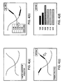
- Fig. 4(a)-(d) are drawings showing an example of reference data in which predicted traffic congestion information may be displayed
- Figs. 5(a)-(d) are drawings showing an example of reference data in which predicted traffic congestion information may be displayed;
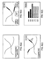
- Figs. 6(a)-(d) are drawings showing an example of reference data in which predicted traffic congestion information may be displayed.
- Figs. 7(a)-(d) are drawings showing an example of reference data in which predicted traffic congestion information may be displayed.
- Fig. 1 is a block diagram showing an exemplary navigation system which may be applied to a vehicle.
- This navigation system may be physically, conceptually, or functionally divided into, for example, a navigation apparatus N and an information communication system C, for example, installed in an information center.
- the navigation apparatus N may be provided with a current position detector 10, such as, for example, a GPS receiver that may receive radio waves sent from an artificial satellite of a satellite navigation system (also known as GPS) and may detect a current position of the vehicle as well as a present day and time.
- a current position detector 10 such as, for example, a GPS receiver that may receive radio waves sent from an artificial satellite of a satellite navigation system (also known as GPS) and may detect a current position of the vehicle as well as a present day and time.
- GPS satellite navigation system
- the navigation apparatus N may be provided with an input unit 20, such as, for example, a portable remote controller, the operation of which may send information to a controller 30 (described later).
- a controller 30 may also be employed as the input unit 20.
- the navigation apparatus N may be provided with, for example, a controller 30, a memory 40, a communication unit 50, and/or an output unit 60.
- the controller 30 may execute, for example, the exemplary navigation methods shown in Figs. 2 and/or 3.
- control of display of the output unit 60 and control required for route guidance of the vehicle may be performed by controller 30 based upon, for example, information from the current position detection unit 10, the input unit 20, the memory 40, and/or the communication unit 50.
- a receiver may be built into the controller 30 and/or may be externally attached to the controller 30.
- the controller 30 may operate using electricity supplied from, for example, a battery via an ignition switch of the vehicle. Accordingly, the controller 30 may initiate execution of a navigation method, such as, for example, the exemplary method shown in Figs. 2 and/or 3. Note that the navigation method may be written in advance as instructions on, for example, a ROM of the controller 30 and may be readable by the controller 30.
- the memory 40 may include, for example, a hard disk. Map data may be stored in the memory 40, for example, in a database or other data structure.
- the communication unit 50 may receive data sent from, for example, a communication unit 80 of the information communication system C. The received data may be output to the controller 30. In addition, the communication unit 50 may send data output from, for example, the controller 30 to, for example, the information communication system C.
- the output unit 60 may include, for example, a display device. Under control of the controller 30, the output unit 60 may display, for example, information required for navigation on a display panel.
- the information communication system C may communicate with the navigation apparatus N, and may be provided with, for example, a controller 70, the communication unit 80, and/or a memory 90.
- the controller 70 may execute, for example, the exemplary navigation methods shown in Figs. 2 and/or 3.
- the controller may control, for example, storage or manipulation of data from, for example, the communication unit 80, storing data in the memory 90, and outputting data from the memory 90 to the communication unit 80.
- the communication unit 80 may receive data from, for example, the communication unit 50 of the navigation apparatus N and/or from, for example, a road traffic information communication system T (hereinafter also referred to as VICS (registered trademark) T), which it may output to the controller 70.
- the communication unit 80 may also send data from the controller 70 to the navigation apparatus N.
- the road traffic information communication system T may be designed so as to send information including traffic conditions such as a link travel time, vehicle speed, traffic congestion degree, roads closed to traffic and traffic regulations as traffic information data.
- each road may consist of a plurality of componential units called links.
- Each link may be separated and defined by, for example, an intersection, an intersection having more than three roads, a curve, and/or a point at which the road type changes.
- a link travel time is the amount of time necessary to travel a particular link.
- the memory 90 may consist of, for example, a hard disk. Traffic information, statistical traffic information, and/or predictive traffic information may be stored in the memory 90, for example, in a database or other data structure that may be readable by the controller 70.
- the traffic information may include a link travel time, vehicle speed, traffic congestion degree, and/or roads closed due to traffic and traffic regulations. Such information may be sent from, for example, the road traffic information communication system T.
- the statistical traffic information may include past traffic information that may be sent from, for example, the road traffic information communication system T and may be statistically processed.
- the predictive traffic information may be future traffic information data that may be calculated from, for example, traffic information and/or statistical traffic information.
- Traffic congestion degrees may include degrees of traffic congestion determined by, for example, a vehicle speed and may be rated according to, for example, a scale of four (4) levels. For example, in order of traffic congestion degree, "Congested”, “Crowded”, “Not congested”, and "Uncertain” may be used as levels, for example, as shown in table 1. Note that, in general, traffic congestion degrees may be rated according to any scale including two or more degrees.
- the controller 30 may execute, for example, the exemplary navigation method shown in Fig. 2, and the controller 70 may execute, for example, the exemplary navigation method shown in Fig. 3.
- the controllers 30, 70 individually.
- step 101 predictive traffic information (e.g., as shown in Fig. 4(a), Fig. 5(a), Fig. 6(a), and Fig. 7(a)) may be requested.
- the controller 30 may request predicted traffic congestion information base on, for example and input from the input unit 20.
- the request may be sent to, for example, controller 70 of the information to the information communication system C via, for example, the communication units 50, 80.
- the controller 30, may output display area information including, for example, road information on a map displayed on an output unit 60 of the navigation apparatus N, map area information, and/or current position information to the controller 70 of the information to the information communication system C via, for example, the communication units 50, 80.
- the display area information may also include, for example, a destination, points passed, and/or a route to a destination.
- step 201 of Fig. 3 a determination is made whether a request (e.g., step 101) has been received.
- controller 70 may receive a request to send predicted traffic congestion information along with the sent display area information and via communication unit 80. If a request has been received, operation continues to step 202.
- step 202n is set to 1.
- traffic congestion is predicted.
- the controller 70 may predict traffic information based on predictive traffic information, stored in, for example, memory 90.
- the controller 70 may use the predictive traffic information calculated from, for example, the statistical traffic information data in memory 90, and may search link travel times in a target area received in, for example, the display area information. This search may be initiated from, for example, a current time and may be executed for a maximum transition duration of X minutes at minimum predictive time period Ta-minute intervals.
- the minimum prediction period Ta may be 5 minutes and the maximum transition duration X may be longer, for example, 30 minutes.
- the traffic congestion prediction processing may be performed over a period of 30 minutes at 5-minute intervals. Operation continues to step 204.
- step 204 it is determined whether there is a time at which a link travel time is conspicuously changed compared to, for example, a previous travel time for that link traffic information. This determination may be made, for example, by controller 70. If there is such time at which a link travel time is conspicuously changed, operation continues to step 205. If there is not such time at which a link travel time is conspicuously changed, operation continues to sep 206.
- a time tn' at which the link travel time is changed and corresponding predicted traffic congestion information at the time tn' is extracted.
- a link travel time may be considered conspicuously changed when, for example, a difference between the link travel time being considered and a precious link travel time (for example, at a time Xn-1) is more than a predetermined value, for example, within a minimum prediction time period Ta.
- link travel times may be considered changed if the link travel times are doubled compared to one or more previous values.
- predicted traffic congestion information may include, for example, locations of traffic congestion, link travel times, and traffic congestion degrees, and/or the like.
- the maximum predictive time Y is a setting time period, for example, 120 minutes.
- the minimum predictive time Ta is 5 minutes and the maximum transition duration X is 30 minutes
- the traffic congestion prediction processing is performed over a period of 30 minutes at 5-minute intervals from a current time. More specifically, the traffic congestion prediction processing is executed from the current time to 120 minutes later.
- step 207 If, in step 207, the current duration of predicted traffic information Xn is longer than maximum predictive time Y, operation continues to sep 209.
- step 209 a time tn' at which a link travel time is conspicuously changed, predicted traffic congestion information at time tn', or predicted traffic congestion information which is Xn minutes later than the predicted traffic congestion is output.
- the information may be output, for example, by controller 70 to controller 30 of the navigation apparatus N via communication units 50, 80.
- step 102 a determination is made whether predicted traffic information (e.g., a time tn' at which a link travel time is conspicuously changed, predicted traffic congestion information at time tn', or predicted traffic congestion information which is Xn minutes later than the predicted traffic congestion) is received. This determination may be made by, for example, the controller 30. If it is received, operation continues to step 103.
- predicted traffic information e.g., a time tn' at which a link travel time is conspicuously changed, predicted traffic congestion information at time tn', or predicted traffic congestion information which is Xn minutes later than the predicted traffic congestion
- step 103 the time tn' at which the received link travel time is conspicuously changed or a time which is passed over the maximum transition duration is displayed, for example, as shown in Figs. 4(b), 5(b), 6(b), and 7(b). This information may be displayed, for example, by controller 30 on output unit 60.
- a time at which is a setting time period later from a current time, or a time which is passed over the maximum transition duration is displayed, for example, on a display panel.
- the time at which the link travel time is conspicuously changed or the time which is passed over the maximum transition duration may also be displayed, for example, on the display panel.
- the controller 30 may display each predictive time at which link travel times are conspicuously changed (for example, as found in step 205) as shown in Fig. 4(b).
- the controller 30 may display each predictive time of predicted traffic congestion information at maximum x-minute (e.g., 30 mins.) transition duration intervals (for example, as found in step 206) when link travel times in the display area have no change.
- a current time and preceding/following time of the current time may be displayed, for example, on a display panel.
- time tn' at which a link travel time is conspicuously changed may be displayed as preceding/following times of the current time. For example, as shown in Fig. 6(b) "30 minutes before” or “20 minutes after” the current time are times at which a link travel time is conspicuously changed.
- the current time and the preceding/following time period at maximum x-minute transition duration intervals (30-minute intervals in Fig. 7(b)) may be shown when link travel times in the display area have no change.
- step 104 it is determined whether a desired time or a preceding/following time of the desired time is selected.
- a desired time or a preceding/following time for example displayed on the display as shown in Figs. 4(b), 5(b), 6(b), and 7(b), may be selected by a user, for example, through operation of the input unit 20. If a desired time or a preceding/following time of the desired time is selected, the extracted and predicted traffic congestion information at the desired time are displayed in step 105. Such may be displayed, for example, on the output unit 60, as shown in Figs. 4(c), 5(c), 6(c), and 7(c) (for example, thick line segments may indicate traffic congestion locations). Operation continues to step 106.
- step 106 it is determined whether a congestion location is selected.
- a congestion location may be selected, for example, by the user through operation of the input unit 20. If a congestion location is selected, link travel time information for each time regarding the selected traffic congestion location is output in step 107.
- the information may be output on the output unit 60, as shown in Figs. 4(d), 5(d), 6(d), and 7(d), wherein the link travel time information for each time may be displayed, for example, as a histogram.
- each extracted link travel times where there is a link travel time which is conspicuously changed may be displayed.
- each time link travel times at maximum x-minute transition duration intervals may be displayed when link travel times in the display area have no change. Then, operation of the method ends.
- the time tn' is extracted with predicted traffic congestion information at the time tn'.
- traffic congestion prediction processing starts from a current time since the current time may be a setting time.
- the user may specify a setting time, for example, 10:00 a.m. of a next day, execute traffic congestion prediction processing at the specified time, and then may display the predicted traffic congestion information at the time.
- the information communication system C receives VICS data from the road traffic information communication system T, executes various data processing, and sends the data to the navigation apparatus N.
- the navigation apparatus N may directly receive VICS data from the road traffic information communication system T and then execute the processing.
- a personal computer, cellular phone, PDA, or any other device containing a capable controller 30 may be used in place of the navigation apparatus N.
Abstract
Systems and methods of displaying predicted traffic congestion information may predict
traffic congestion information at each of a plurality of times through statistical processing
of traffic information. If the predicted traffic congestion information is not conspicuously
changed at a setting time or within a predetermined time period of the setting time, the
predicted traffic congestion information may be displayed at display times defined by
regular time intervals. If the predicted traffic congestion information is conspicuously
changed at a setting time or within a predetermined time period of the setting time, the
predicted traffic congestion information may be displayed at display times defined by the
times at which the predicted traffic congestion information is conspicuously changed.
Description
- The disclosure of Japanese Patent Application Nos. 2003-434703 filed on December 26, 2003 and 2003-284930 filed on September 29, 2004 including the specifications, drawings, and abstracts are incorporated herein by reference in their entirety.
- Related technical fields include systems and methods of displaying predicted traffic congestion information.
- A conventional road map display device is provided with a road map memory in which statistical traffic congestion information data corresponding to days of the week and time periods is stored. When a day of the week or time period is specified, traffic congestion information for the time period of the specified day are displayed on a road map by means of a superimposed display. (Refer to, for example, Japanese Unexamined Patent Application Publication No. 9-113290).
- In, for example, the above-described conventional road map display device, only traffic congestion information for the one specified time period of the specified day is displayed so that a user can not know about the transition of traffic congestion information for the specified time period, i.e., whether it is getting worse or better. Thus, a user may not efficiently plan a trip.
- Accordingly, various implementations provide a method of displaying predicted traffic congestion information including predicting traffic congestion information at each of a plurality of times through statistical processing of traffic information. If the predicted traffic congestion information is conspicuously changed within a predetermined time period of a setting time, the predicted traffic congestion information may be display at display times defined by the times at which the predicted traffic congestion information is conspicuously changed.
- Various implementations provide a navigation system including a controller that may predict traffic congestion information at each of a plurality of times through statistical processing of traffic information. The controller may display the predicted traffic congestion information at display times by the times at which the predicted traffic congestion information is conspicuously changed if the predicted traffic congestion information is conspicuously changed within a predetermined time period of a setting time.
- Examples will now be described with reference to the accompanying drawings, wherein:
- Fig. 1 is a block diagram showing an exemplary navigation system;
- Fig. 2 is a flowchart showing an exemplary navigation method;
- Fig. 3 is a flowchart showing another exemplary navigation method;
- Fig. 4(a)-(d) are drawings showing an example of reference data in which predicted traffic congestion information may be displayed;
- Figs. 5(a)-(d) are drawings showing an example of reference data in which predicted traffic congestion information may be displayed;
- Figs. 6(a)-(d) are drawings showing an example of reference data in which predicted traffic congestion information may be displayed; and
- Figs. 7(a)-(d) are drawings showing an example of reference data in which predicted traffic congestion information may be displayed.
- Fig. 1 is a block diagram showing an exemplary navigation system which may be applied to a vehicle. This navigation system may be physically, conceptually, or functionally divided into, for example, a navigation apparatus N and an information communication system C, for example, installed in an information center. The navigation apparatus N may be provided with a
current position detector 10, such as, for example, a GPS receiver that may receive radio waves sent from an artificial satellite of a satellite navigation system (also known as GPS) and may detect a current position of the vehicle as well as a present day and time. - In addition, the navigation apparatus N may be provided with an
input unit 20, such as, for example, a portable remote controller, the operation of which may send information to a controller 30 (described later). For example, a touch panel, keyboard, mouse, and/or a voice recognition device may also be employed as theinput unit 20. - Furthermore, the navigation apparatus N may be provided with, for example, a
controller 30, amemory 40, acommunication unit 50, and/or anoutput unit 60. Thecontroller 30 may execute, for example, the exemplary navigation methods shown in Figs. 2 and/or 3. During execution of the program, for example, control of display of theoutput unit 60 and control required for route guidance of the vehicle may be performed bycontroller 30 based upon, for example, information from the currentposition detection unit 10, theinput unit 20, thememory 40, and/or thecommunication unit 50. - A receiver may be built into the
controller 30 and/or may be externally attached to thecontroller 30. Thecontroller 30 may operate using electricity supplied from, for example, a battery via an ignition switch of the vehicle. Accordingly, thecontroller 30 may initiate execution of a navigation method, such as, for example, the exemplary method shown in Figs. 2 and/or 3. Note that the navigation method may be written in advance as instructions on, for example, a ROM of thecontroller 30 and may be readable by thecontroller 30. - The
memory 40 may include, for example, a hard disk. Map data may be stored in thememory 40, for example, in a database or other data structure. - The
communication unit 50 may receive data sent from, for example, acommunication unit 80 of the information communication system C. The received data may be output to thecontroller 30. In addition, thecommunication unit 50 may send data output from, for example, thecontroller 30 to, for example, the information communication system C. - The
output unit 60 may include, for example, a display device. Under control of thecontroller 30, theoutput unit 60 may display, for example, information required for navigation on a display panel. - The information communication system C may communicate with the navigation apparatus N, and may be provided with, for example, a
controller 70, thecommunication unit 80, and/or amemory 90. Thecontroller 70 may execute, for example, the exemplary navigation methods shown in Figs. 2 and/or 3. The controller may control, for example, storage or manipulation of data from, for example, thecommunication unit 80, storing data in thememory 90, and outputting data from thememory 90 to thecommunication unit 80. - The
communication unit 80 may receive data from, for example, thecommunication unit 50 of the navigation apparatus N and/or from, for example, a road traffic information communication system T (hereinafter also referred to as VICS (registered trademark) T), which it may output to thecontroller 70. Thecommunication unit 80 may also send data from thecontroller 70 to the navigation apparatus N. Note that the road traffic information communication system T may be designed so as to send information including traffic conditions such as a link travel time, vehicle speed, traffic congestion degree, roads closed to traffic and traffic regulations as traffic information data. - As used herein, the term link refers to, for example, a road or portion of a road. For example, according to one type of road data, each road may consist of a plurality of componential units called links. Each link may be separated and defined by, for example, an intersection, an intersection having more than three roads, a curve, and/or a point at which the road type changes. A link travel time is the amount of time necessary to travel a particular link.
- The
memory 90 may consist of, for example, a hard disk. Traffic information, statistical traffic information, and/or predictive traffic information may be stored in thememory 90, for example, in a database or other data structure that may be readable by thecontroller 70. The traffic information may include a link travel time, vehicle speed, traffic congestion degree, and/or roads closed due to traffic and traffic regulations. Such information may be sent from, for example, the road traffic information communication system T. - The statistical traffic information may include past traffic information that may be sent from, for example, the road traffic information communication system T and may be statistically processed. The predictive traffic information may be future traffic information data that may be calculated from, for example, traffic information and/or statistical traffic information. Traffic congestion degrees may include degrees of traffic congestion determined by, for example, a vehicle speed and may be rated according to, for example, a scale of four (4) levels. For example, in order of traffic congestion degree, "Congested", "Crowded", "Not congested", and "Uncertain" may be used as levels, for example, as shown in table 1. Note that, in general, traffic congestion degrees may be rated according to any scale including two or more degrees.
Congested Crowded Not Congested General road V≤10km/h 10km/h<V≤20km/h 20km/h<V Urban highway V≤20km/h 20km/h<V≤40km/h 40km/h<V Intercity highway V≤40km/h 40km/h<V≤60km/h 60km/h<V - As described above, the
controller 30 may execute, for example, the exemplary navigation method shown in Fig. 2, and thecontroller 70 may execute, for example, the exemplary navigation method shown in Fig. 3. Although, either or both of the exemplary methods shown in Figs. 2 and 3 may be executed by either of thecontrollers - As shown in Fig. 2. In
step 101, predictive traffic information (e.g., as shown in Fig. 4(a), Fig. 5(a), Fig. 6(a), and Fig. 7(a)) may be requested. For example, thecontroller 30 may request predicted traffic congestion information base on, for example and input from theinput unit 20. The request may be sent to, for example,controller 70 of the information to the information communication system C via, for example, thecommunication units controller 30, for example, may output display area information including, for example, road information on a map displayed on anoutput unit 60 of the navigation apparatus N, map area information, and/or current position information to thecontroller 70 of the information to the information communication system C via, for example, thecommunication units - Then, in
step 201 of Fig. 3, a determination is made whether a request (e.g., step 101) has been received. For example,controller 70 may receive a request to send predicted traffic congestion information along with the sent display area information and viacommunication unit 80. If a request has been received, operation continues to step 202. In step 202n is set to 1. For example, thecontroller 70 may set, for example, enumeration data as n=1. Then, instep 203, traffic congestion is predicted. For example, thecontroller 70 may predict traffic information based on predictive traffic information, stored in, for example,memory 90. Specifically, thecontroller 70 may use the predictive traffic information calculated from, for example, the statistical traffic information data inmemory 90, and may search link travel times in a target area received in, for example, the display area information. This search may be initiated from, for example, a current time and may be executed for a maximum transition duration of X minutes at minimum predictive time period Ta-minute intervals. For example, the minimum prediction period Ta may be 5 minutes and the maximum transition duration X may be longer, for example, 30 minutes. Thus, for example, the traffic congestion prediction processing may be performed over a period of 30 minutes at 5-minute intervals. Operation continues to step 204. - In
step 204, it is determined whether there is a time at which a link travel time is conspicuously changed compared to, for example, a previous travel time for that link traffic information. This determination may be made, for example, bycontroller 70. If there is such time at which a link travel time is conspicuously changed, operation continues to step 205. If there is not such time at which a link travel time is conspicuously changed, operation continues tosep 206. - In
step 205, a time tn' at which the link travel time is changed and corresponding predicted traffic congestion information at the time tn' is extracted. A link travel time may be considered conspicuously changed when, for example, a difference between the link travel time being considered and a precious link travel time (for example, at a time Xn-1) is more than a predetermined value, for example, within a minimum prediction time period Ta. For instance, link travel times may be considered changed if the link travel times are doubled compared to one or more previous values. In addition, predicted traffic congestion information may include, for example, locations of traffic congestion, link travel times, and traffic congestion degrees, and/or the like. - In
step 206, predicted traffic congestion information in Xn minutes is extracted. Note that, for example, in the first traffic congestion prediction processing, Xn is equal to X1 since an enumeration data is n=1. Therefore, the traffic congestion may be predicted starting from a current time to X1 minutes later, (e.g. 30 minutes later). Operation continues to step 207. - In
step 207 is determined whether Y≤Xn. For example, according to extracted traffic congestion predictive information instep step 208. Then operation returns to step 203. Accordingly, for example, the second traffic congestion prediction processing from X1 to X2, for example, from 30 minutes to 60 minutes are executed and the determination processing instep 207 is repeated. - The maximum predictive time Y is a setting time period, for example, 120 minutes. When the minimum predictive time Ta is 5 minutes and the maximum transition duration X is 30 minutes, the traffic congestion prediction processing is performed over a period of 30 minutes at 5-minute intervals from a current time. More specifically, the traffic congestion prediction processing is executed from the current time to 120 minutes later.
- If, in
step 207, the current duration of predicted traffic information Xn is longer than maximum predictive time Y, operation continues tosep 209. Instep 209, a time tn' at which a link travel time is conspicuously changed, predicted traffic congestion information at time tn', or predicted traffic congestion information which is Xn minutes later than the predicted traffic congestion is output. The information may be output, for example, bycontroller 70 tocontroller 30 of the navigation apparatus N viacommunication units - Returning to Fig. 2, in step 102 a determination is made whether predicted traffic information (e.g., a time tn' at which a link travel time is conspicuously changed, predicted traffic congestion information at time tn', or predicted traffic congestion information which is Xn minutes later than the predicted traffic congestion) is received. This determination may be made by, for example, the
controller 30. If it is received, operation continues to step 103. - In
step 103, the time tn' at which the received link travel time is conspicuously changed or a time which is passed over the maximum transition duration is displayed, for example, as shown in Figs. 4(b), 5(b), 6(b), and 7(b). This information may be displayed, for example, bycontroller 30 onoutput unit 60. - In Figs. 4(b) and 5(b), a time at which is a setting time period later from a current time, or a time which is passed over the maximum transition duration is displayed, for example, on a display panel. The time at which the link travel time is conspicuously changed or the time which is passed over the maximum transition duration may also be displayed, for example, on the display panel. At this time, the
controller 30 may display each predictive time at which link travel times are conspicuously changed (for example, as found in step 205) as shown in Fig. 4(b). As shown in Fig. 5(b), thecontroller 30 may display each predictive time of predicted traffic congestion information at maximum x-minute (e.g., 30 mins.) transition duration intervals (for example, as found in step 206) when link travel times in the display area have no change. - Alternatively, as shown in Figs. 6(b) and 7(b), a current time and preceding/following time of the current time may be displayed, for example, on a display panel. Also in the display panel, time tn' at which a link travel time is conspicuously changed may be displayed as preceding/following times of the current time. For example, as shown in Fig. 6(b) "30 minutes before" or "20 minutes after" the current time are times at which a link travel time is conspicuously changed. Also as shown in Fig. 7(b) the current time and the preceding/following time period at maximum x-minute transition duration intervals (30-minute intervals in Fig. 7(b)) may be shown when link travel times in the display area have no change.
- Returning to Fig. 2, in
step 104 it is determined whether a desired time or a preceding/following time of the desired time is selected. A desired time or a preceding/following time, for example displayed on the display as shown in Figs. 4(b), 5(b), 6(b), and 7(b), may be selected by a user, for example, through operation of theinput unit 20. If a desired time or a preceding/following time of the desired time is selected, the extracted and predicted traffic congestion information at the desired time are displayed instep 105. Such may be displayed, for example, on theoutput unit 60, as shown in Figs. 4(c), 5(c), 6(c), and 7(c) (for example, thick line segments may indicate traffic congestion locations). Operation continues to step 106. - In
step 106, it is determined whether a congestion location is selected. A congestion location may be selected, for example, by the user through operation of theinput unit 20. If a congestion location is selected, link travel time information for each time regarding the selected traffic congestion location is output instep 107. For example, the information may be output on theoutput unit 60, as shown in Figs. 4(d), 5(d), 6(d), and 7(d), wherein the link travel time information for each time may be displayed, for example, as a histogram. As shown in Figs. 4(d) and 6(d), each extracted link travel times where there is a link travel time which is conspicuously changed may be displayed. As shown in Figs. 5(d) and 7(d), each time link travel times at maximum x-minute transition duration intervals may be displayed when link travel times in the display area have no change. Then, operation of the method ends. - According to the above described examples, it is possible for a user to obtain predicted traffic congestion information at each time corresponding to the transition of link travel times. That is, if a link travel time is conspicuously changed, it is possible to obtain predicted traffic congestion information for shorter time periods and if the transition of link travel times is not conspicuous, predicted traffic congestion information at no-changed time periods can be reduced. Therefore, predicted traffic congestion information corresponding to the transition of link travel times can be obtained.
- Further, according to the above described examples, after it is determined whether there is a time at which a link travel time is conspicuously changed, the time tn' is extracted with predicted traffic congestion information at the time tn'. However, it may only be determined whether there is a time at which at least one of link travel times and traffic congestion degrees is conspicuously changed and the time tn' may be extracted with predicted traffic congestion information at the time tn'.
- Further, according to the above described examples, traffic congestion prediction processing starts from a current time since the current time may be a setting time. However, the user may specify a setting time, for example, 10:00 a.m. of a next day, execute traffic congestion prediction processing at the specified time, and then may display the predicted traffic congestion information at the time.
- Furthermore, according to the above described examples, the information communication system C receives VICS data from the road traffic information communication system T, executes various data processing, and sends the data to the navigation apparatus N. However, the navigation apparatus N may directly receive VICS data from the road traffic information communication system T and then execute the processing.
- Note that a personal computer, cellular phone, PDA, or any other device containing a
capable controller 30 may be used in place of the navigation apparatus N. - While various features have been described in conjunction with the examples outlined above, various alternatives, modifications, variations and/or improvements of those features may be possible. Accordingly, the various examples, as set forth above, are intended to be illustrative. Various changes may be made without departing from the broad spirit and scope of underlining principles.
Claims (20)
- A method of displaying predicted traffic congestion information, comprising:predicting traffic congestion information at each of a plurality of times through statistical processing of traffic information; anddisplaying, if the predicted traffic congestion information is conspicuously changed within a predetermined time period of a setting time, the predicted traffic congestion information at display times defined by the times at which the predicted traffic congestion information is conspicuously changed.
- The method of claim 1, further comprising:displaying, if the predicted traffic congestion information is not conspicuously changed within a predetermined time period of the setting time, the predicted traffic congestion information at display times defined by regular time intervals.
- The method of claim 1, further comprising:selecting one of the display times; anddisplaying predicted traffic congestion information at the selected display time.
- The method of claim 1, wherein the setting time is a current time or a time specified by a user.
- The method of claim 1, wherein:the predicted traffic congestion information comprises a link travel time or a traffic congestion degree.
- The method of claim 1, wherein:the predicted traffic congestion information is conspicuously changed if the link travel time or traffic congestion degree is changed by more than a predetermined value.
- The method of claim 1, further comprising:displaying the predicted traffic congestion information as preceding or following times of a current time.
- A storage medium storing a set of program instructions executable on a data processing device and usable for performing the method recited in claim 1.
- A navigation system, comprising:a controller that:predicts traffic congestion information at each of a plurality of times through statistical processing of traffic information, anddisplays the predicted traffic congestion information at display times defined by the times at which the predicted traffic congestion information is conspicuously changed if the predicted traffic congestion information is conspicuously changed within a predetermined time period of a setting time.
- The system of claim 9, wherein the controller:displays the predicted traffic congestion information at display times defined by regular time intervals if the predicted traffic congestion information is not conspicuously changed within a predetermined time period of the setting time.
- The system of claim 9, wherein the controller:selects one of the display times; anddisplays predicted traffic congestion information at the selected display time.
- The system of claim 9, wherein the setting time is a current time or a time specified by a user.
- The system of claim 9, wherein:the predicted traffic congestion information comprises a link travel time or a traffic congestion degree.
- The system of claim 9, wherein:the predicted traffic congestion information is conspicuously changed if the link travel time or traffic congestion degree is changed by more than a predetermined value.
- The system of claim 9, wherein the controller:displays the predicted traffic congestion information as preceding or following times of a current time.
- A navigation information center comprising the system of claim 9.
- A navigation apparatus comprising the system of claim 9.
- The navigation apparatus of claim 17, wherein the navigation apparatus comprises at least one of an apparatus installed in a vehicle, a personal computer, a cellular phone, and a PDA.
- A navigation system, comprising:means for predicting traffic congestion information at each of a plurality of times through statistical processing of traffic information; andmeans for displaying the predicted traffic congestion information at display times defined by the times at which the predicted traffic congestion information is conspicuously changed if the predicted traffic congestion information is conspicuously changed within a predetermined time period of a setting time.
- The system of claim 19, further comprising:means for selecting one of the display times; andmeans for displaying predicted traffic congestion information at the selected display time.
Applications Claiming Priority (4)
| Application Number | Priority Date | Filing Date | Title |
|---|---|---|---|
| JP2003434703 | 2003-12-26 | ||
| JP2003434703 | 2003-12-26 | ||
| JP2004284930 | 2004-09-29 | ||
| JP2004284930A JP3928639B2 (en) | 2003-12-26 | 2004-09-29 | Car navigation system |
Publications (1)
| Publication Number | Publication Date |
|---|---|
| EP1548407A1 true EP1548407A1 (en) | 2005-06-29 |
Family
ID=34554889
Family Applications (1)
| Application Number | Title | Priority Date | Filing Date |
|---|---|---|---|
| EP04030624A Withdrawn EP1548407A1 (en) | 2003-12-26 | 2004-12-23 | System and method of displaying predicted traffic information |
Country Status (4)
| Country | Link |
|---|---|
| US (1) | US20050140525A1 (en) |
| EP (1) | EP1548407A1 (en) |
| JP (1) | JP3928639B2 (en) |
| CN (1) | CN1637382A (en) |
Cited By (4)
| Publication number | Priority date | Publication date | Assignee | Title |
|---|---|---|---|---|
| EP1635141A1 (en) | 2004-09-08 | 2006-03-15 | Aisin Aw Co., Ltd. | Navigation apparatus and method |
| WO2007083899A3 (en) * | 2006-01-19 | 2009-08-20 | Lg Electronics Inc | Method and apparatus for providing congestion and travel time information to users |
| CN110914882A (en) * | 2017-07-05 | 2020-03-24 | 三菱电机株式会社 | Display system and display method |
| CN112530157A (en) * | 2020-10-16 | 2021-03-19 | 浙江工业大学 | Road traffic congestion propagation prediction method based on knowledge graph and Conv1D-LSTM-D |
Families Citing this family (15)
| Publication number | Priority date | Publication date | Assignee | Title |
|---|---|---|---|---|
| JP2007011558A (en) * | 2005-06-29 | 2007-01-18 | Nissan Motor Co Ltd | Apparatus and method for predicting traffic jam |
| US20070208498A1 (en) * | 2006-03-03 | 2007-09-06 | Inrix, Inc. | Displaying road traffic condition information and user controls |
| US8700296B2 (en) | 2006-03-03 | 2014-04-15 | Inrix, Inc. | Dynamic prediction of road traffic conditions |
| US7899611B2 (en) * | 2006-03-03 | 2011-03-01 | Inrix, Inc. | Detecting anomalous road traffic conditions |
| US7912628B2 (en) | 2006-03-03 | 2011-03-22 | Inrix, Inc. | Determining road traffic conditions using data from multiple data sources |
| US7908076B2 (en) * | 2006-08-18 | 2011-03-15 | Inrix, Inc. | Representative road traffic flow information based on historical data |
| JP4891792B2 (en) * | 2007-01-26 | 2012-03-07 | クラリオン株式会社 | Traffic information distribution method and traffic information distribution device |
| CN101339042B (en) * | 2008-08-11 | 2011-04-13 | 肖禄生 | Personalized dynamic road condition information creation and navigation system |
| US9200913B2 (en) * | 2008-10-07 | 2015-12-01 | Telecommunication Systems, Inc. | User interface for predictive traffic |
| EP2422330B1 (en) | 2009-04-22 | 2015-02-25 | Inrix, Inc. | Predicting expected road traffic conditions based on historical and current data |
| US20130222154A1 (en) * | 2012-02-24 | 2013-08-29 | Research In Motion Limited | System and method for providing traffic notifications |
| EP2986944A1 (en) * | 2013-04-17 | 2016-02-24 | TomTom Navigation B.V. | Routing engine |
| CN104933860B (en) * | 2015-05-20 | 2017-07-11 | 重庆大学 | Bus traffic congestion delay time at stop Forecasting Methodology based on gps data |
| JP6529429B2 (en) * | 2015-12-22 | 2019-06-12 | 本田技研工業株式会社 | Traffic information output system and traffic information output method |
| CN106052709A (en) * | 2016-05-16 | 2016-10-26 | 腾讯科技(深圳)有限公司 | Congestion information processing method and device |
Citations (3)
| Publication number | Priority date | Publication date | Assignee | Title |
|---|---|---|---|---|
| JPH09113290A (en) * | 1995-10-18 | 1997-05-02 | Sumitomo Electric Ind Ltd | Road map displaying device |
| JPH11281378A (en) * | 1998-03-26 | 1999-10-15 | Sanyo Electric Co Ltd | Navigation device |
| JP2001093078A (en) * | 1999-09-21 | 2001-04-06 | Omron Corp | Congesting situation display system |
Family Cites Families (26)
| Publication number | Priority date | Publication date | Assignee | Title |
|---|---|---|---|---|
| US5164904A (en) * | 1990-07-26 | 1992-11-17 | Farradyne Systems, Inc. | In-vehicle traffic congestion information system |
| JP2771911B2 (en) * | 1991-08-09 | 1998-07-02 | 三菱電機株式会社 | Car navigation system |
| US5610821A (en) * | 1994-11-18 | 1997-03-11 | Ibm Corporation | Optimal and stable route planning system |
| DE69535394T2 (en) * | 1994-12-28 | 2007-10-31 | Omron Corp. | Traffic Information System |
| JP3743037B2 (en) * | 1995-11-01 | 2006-02-08 | 株式会社日立製作所 | Information providing method to mobile terminal, information providing system, and mobile terminal |
| US5790974A (en) * | 1996-04-29 | 1998-08-04 | Sun Microsystems, Inc. | Portable calendaring device having perceptual agent managing calendar entries |
| SE9800280L (en) * | 1998-01-30 | 1999-05-25 | Dinbis Ab | Method and device for network control of traffic |
| EP2009609B1 (en) * | 1998-11-23 | 2010-10-27 | Integrated Transport Information Services Limited | Instantaneous traffic monitoring system |
| US6466862B1 (en) * | 1999-04-19 | 2002-10-15 | Bruce DeKock | System for providing traffic information |
| US6490519B1 (en) * | 1999-09-27 | 2002-12-03 | Decell, Inc. | Traffic monitoring system and methods for traffic monitoring and route guidance useful therewith |
| US6615130B2 (en) * | 2000-03-17 | 2003-09-02 | Makor Issues And Rights Ltd. | Real time vehicle guidance and traffic forecasting system |
| US6480783B1 (en) * | 2000-03-17 | 2002-11-12 | Makor Issues And Rights Ltd. | Real time vehicle guidance and forecasting system under traffic jam conditions |
| US6282486B1 (en) * | 2000-04-03 | 2001-08-28 | International Business Machines Corporation | Distributed system and method for detecting traffic patterns |
| US6650948B1 (en) * | 2000-11-28 | 2003-11-18 | Applied Generics Limited | Traffic flow monitoring |
| JP3849435B2 (en) * | 2001-02-23 | 2006-11-22 | 株式会社日立製作所 | Traffic situation estimation method and traffic situation estimation / provision system using probe information |
| US6594576B2 (en) * | 2001-07-03 | 2003-07-15 | At Road, Inc. | Using location data to determine traffic information |
| US6539300B2 (en) * | 2001-07-10 | 2003-03-25 | Makor Issues And Rights Ltd. | Method for regional system wide optimal signal timing for traffic control based on wireless phone networks |
| US6922629B2 (en) * | 2001-08-10 | 2005-07-26 | Aisin Aw Co., Ltd. | Traffic information retrieval method, traffic information retrieval system, mobile communication device, and network navigation center |
| CN100353142C (en) * | 2001-10-25 | 2007-12-05 | 爱信艾达株式会社 | Information display system |
| US7221287B2 (en) * | 2002-03-05 | 2007-05-22 | Triangle Software Llc | Three-dimensional traffic report |
| DE60332275D1 (en) * | 2002-12-24 | 2010-06-02 | Navitime Japan Co Ltd | SERVER, SYSTEM AND METHOD FOR ROUTE SEARCH |
| JP4255007B2 (en) * | 2003-04-11 | 2009-04-15 | 株式会社ザナヴィ・インフォマティクス | Navigation device and travel time calculation method thereof |
| US7440842B1 (en) * | 2003-05-09 | 2008-10-21 | Dimitri Vorona | System for transmitting, processing, receiving, and displaying traffic information |
| JP4346472B2 (en) * | 2004-02-27 | 2009-10-21 | 株式会社ザナヴィ・インフォマティクス | Traffic information prediction device |
| EP1640691B1 (en) * | 2004-09-24 | 2015-05-06 | Aisin Aw Co., Ltd. | Navigation systems, methods, and programs |
| US7908076B2 (en) * | 2006-08-18 | 2011-03-15 | Inrix, Inc. | Representative road traffic flow information based on historical data |
-
2004
- 2004-09-29 JP JP2004284930A patent/JP3928639B2/en not_active Expired - Fee Related
- 2004-12-03 US US11/002,792 patent/US20050140525A1/en not_active Abandoned
- 2004-12-23 EP EP04030624A patent/EP1548407A1/en not_active Withdrawn
- 2004-12-24 CN CNA2004100817305A patent/CN1637382A/en active Pending
Patent Citations (3)
| Publication number | Priority date | Publication date | Assignee | Title |
|---|---|---|---|---|
| JPH09113290A (en) * | 1995-10-18 | 1997-05-02 | Sumitomo Electric Ind Ltd | Road map displaying device |
| JPH11281378A (en) * | 1998-03-26 | 1999-10-15 | Sanyo Electric Co Ltd | Navigation device |
| JP2001093078A (en) * | 1999-09-21 | 2001-04-06 | Omron Corp | Congesting situation display system |
Non-Patent Citations (3)
| Title |
|---|
| PATENT ABSTRACTS OF JAPAN vol. 1997, no. 09 30 September 1997 (1997-09-30) * |
| PATENT ABSTRACTS OF JAPAN vol. 2000, no. 01 31 January 2000 (2000-01-31) * |
| PATENT ABSTRACTS OF JAPAN vol. 2000, no. 21 3 August 2001 (2001-08-03) * |
Cited By (6)
| Publication number | Priority date | Publication date | Assignee | Title |
|---|---|---|---|---|
| EP1635141A1 (en) | 2004-09-08 | 2006-03-15 | Aisin Aw Co., Ltd. | Navigation apparatus and method |
| US7739029B2 (en) | 2004-09-08 | 2010-06-15 | Aisin Aw Co., Ltd. | Navigation apparatus and method with traffic ranking and display |
| WO2007083899A3 (en) * | 2006-01-19 | 2009-08-20 | Lg Electronics Inc | Method and apparatus for providing congestion and travel time information to users |
| CN101627282B (en) * | 2006-01-19 | 2012-05-23 | Lg电子株式会社 | Method and apparatus for providing congestion and travel time information to users |
| CN110914882A (en) * | 2017-07-05 | 2020-03-24 | 三菱电机株式会社 | Display system and display method |
| CN112530157A (en) * | 2020-10-16 | 2021-03-19 | 浙江工业大学 | Road traffic congestion propagation prediction method based on knowledge graph and Conv1D-LSTM-D |
Also Published As
| Publication number | Publication date |
|---|---|
| CN1637382A (en) | 2005-07-13 |
| US20050140525A1 (en) | 2005-06-30 |
| JP3928639B2 (en) | 2007-06-13 |
| JP2005208040A (en) | 2005-08-04 |
Similar Documents
| Publication | Publication Date | Title |
|---|---|---|
| EP1548407A1 (en) | System and method of displaying predicted traffic information | |
| US6941222B2 (en) | Navigation system, server system for a navigation system, and computer-readable information recorded medium in which destination prediction program is recorded | |
| US7660663B2 (en) | Traffic information transmitting apparatus, transmitting method, and transmitting program | |
| US8694242B2 (en) | Traveling information creating device, traveling information creating method and program | |
| US6362751B1 (en) | Navigation system with a route exclusion list system | |
| KR100522999B1 (en) | Method for searching car navigation path by using log file | |
| EP1750092A1 (en) | Position information reception device and shape matching method | |
| US8706408B2 (en) | Navigation system and route search method | |
| JP4207793B2 (en) | Route search apparatus and route search method | |
| US20050143906A1 (en) | Systems, methods, and data structures for smoothing navigation data | |
| WO2006070583A1 (en) | Route searching device, route searching method, route searching program, and recording medium | |
| JP3966321B2 (en) | Car navigation system | |
| JP4108150B2 (en) | Road information transmission device and road information display device | |
| JP3960158B2 (en) | Road traffic jam prediction device and program | |
| EP1783722A1 (en) | Position information transmitter, position information receiver, position information transmitting method,and position information transmission program | |
| US20090254267A1 (en) | Route Search System | |
| JP2008082884A (en) | Navigation device | |
| JP2000283780A (en) | Method and system for searching course | |
| JP4470634B2 (en) | Information providing system and program | |
| US11892315B2 (en) | Information processor | |
| EP2040034A1 (en) | Navigation device and method, navigation program, and storage medium | |
| JP4395535B2 (en) | Navigation device, search control method, search control program, and recording medium | |
| JP2008281341A (en) | Navigation device | |
| JP2005010168A (en) | Car navigation system | |
| JP2008082795A (en) | Navigation device, its method, and program |
Legal Events
| Date | Code | Title | Description |
|---|---|---|---|
| PUAI | Public reference made under article 153(3) epc to a published international application that has entered the european phase |
Free format text: ORIGINAL CODE: 0009012 |
|
| AK | Designated contracting states |
Kind code of ref document: A1 Designated state(s): AT BE BG CH CY CZ DE DK EE ES FI FR GB GR HU IE IS IT LI LT LU MC NL PL PT RO SE SI SK TR |
|
| AX | Request for extension of the european patent |
Extension state: AL BA HR LV MK YU |
|
| 17P | Request for examination filed |
Effective date: 20051213 |
|
| AKX | Designation fees paid |
Designated state(s): DE FR GB |
|
| STAA | Information on the status of an ep patent application or granted ep patent |
Free format text: STATUS: THE APPLICATION HAS BEEN WITHDRAWN |
|
| 18W | Application withdrawn |
Effective date: 20110913 |