EP1548403A1 - Apparatus and method for driving mems structure and detecting motion of the driven mems structure using a single electrode - Google Patents
Apparatus and method for driving mems structure and detecting motion of the driven mems structure using a single electrode Download PDFInfo
- Publication number
- EP1548403A1 EP1548403A1 EP04029996A EP04029996A EP1548403A1 EP 1548403 A1 EP1548403 A1 EP 1548403A1 EP 04029996 A EP04029996 A EP 04029996A EP 04029996 A EP04029996 A EP 04029996A EP 1548403 A1 EP1548403 A1 EP 1548403A1
- Authority
- EP
- European Patent Office
- Prior art keywords
- motion
- signal
- mems structure
- driving signal
- driving
- Prior art date
- Legal status (The legal status is an assumption and is not a legal conclusion. Google has not performed a legal analysis and makes no representation as to the accuracy of the status listed.)
- Granted
Links
Images


Classifications
-
- B—PERFORMING OPERATIONS; TRANSPORTING
- B81—MICROSTRUCTURAL TECHNOLOGY
- B81B—MICROSTRUCTURAL DEVICES OR SYSTEMS, e.g. MICROMECHANICAL DEVICES
- B81B7/00—Microstructural systems; Auxiliary parts of microstructural devices or systems
- B81B7/02—Microstructural systems; Auxiliary parts of microstructural devices or systems containing distinct electrical or optical devices of particular relevance for their function, e.g. microelectro-mechanical systems [MEMS]
-
- G—PHYSICS
- G01—MEASURING; TESTING
- G01C—MEASURING DISTANCES, LEVELS OR BEARINGS; SURVEYING; NAVIGATION; GYROSCOPIC INSTRUMENTS; PHOTOGRAMMETRY OR VIDEOGRAMMETRY
- G01C19/00—Gyroscopes; Turn-sensitive devices using vibrating masses; Turn-sensitive devices without moving masses; Measuring angular rate using gyroscopic effects
- G01C19/56—Turn-sensitive devices using vibrating masses, e.g. vibratory angular rate sensors based on Coriolis forces
- G01C19/5776—Signal processing not specific to any of the devices covered by groups G01C19/5607 - G01C19/5719
Definitions
- the present invention relates to an apparatus and a method for driving a MEMS (Micro Electro Mechanical Systems) structure and detecting the motion of the driven MEMS structure.
- MEMS Micro Electro Mechanical Systems
- MEMS has realized the integration of mechanical components into microelectronic elements using semiconductor processes, and promises to revolutionize numerous industrial fields including electronics, mechanics, medical, and defense industries.
- MEMS makes it possible to realize machines and equipments having a hyperfine structure under several ⁇ m.
- sensors fabricated in a hyperfine structure through MEMS technology are embedded in compact devices such as a cellular phone and detect the mechanical motion in the range of several ten nm - several ⁇ m as an electronic signal of several pico F.
- the displacement of the MEMS structure is detected using the amount by which capacitance changes.
- a conventional apparatus for driving a MEMS structure and detecting the motion of the driven MEMS structure is described below.
- FIG 1 is a circuit diagram showing the conventional apparatus for driving a MEMS structure and detecting the motion of the driven MEMS structure.
- the apparatus comprises a driving source 5, a first variable capacitor 6a being supplied with a driving signal from the driving source 5 to drive the MEMS structure, a second variable capacitor 6b serially connected to the first variable capacitor 6a, for detecting the motion of the MEMS structure and supplying a motion signal, and an amplifying circuit 8 connected to the second variable capacitor 6b, for outputting an amplified voltage signal V out with respect to an input signal in a current form.
- FIG 2 is a view showing configurations of the first and the second variable capacitors 6a and 6b of FIG 1.
- the conventional apparatus for driving the MEMS structure and detecting the motion of the driven MEMS structure comprises a first fixed electrode plate 11a supplied with the driving signal, a second fixed electrode plate 11b disposed apart from the first fixed electrode plate 11b by a predetermined distance and opposite to the first fixed electrode plate 11b, and a movable electrode plate 15 integrally formed with the MEMS structure 14, which is supported on a spring 12 and a damper 13 to be movable to a predetermined direction, and located between the first an second fixed electrode plates 11a and 11b.
- the first variable capacitor 6a is embodied by the first fixed electrode plate 11 a and the movable electrode plate 15
- the second fixed electrode plate 11b is embodied by the movable electrode plate 15 and the second fixed electrode plate 11b.
- an aspect of the present invention is to provide an apparatus for driving a MEMS structure and detecting the motion of the driven MEMS structure using a single electrode.
- an apparatus for driving a MEMS structure and detecting motion of the driven MEMS structure using a single electrode comprising: a driving signal generation part for generating and outputting a driving signal to drive the MEMS structure; a motion detection part configured by one single variable capacitor, for detecting the motion of the MEMS structure driven according to the driving signal and outputting a motion current signal corresponding to the motion of the MEMS structure; an amplification part for amplifying the motion current signal output from the motion detection part and outputting a motion voltage signal; a gain adjustment part for amplifying the driving signal input from the driving signal generation part and outputting a driving signal amplified by a predetermined gain; a differential circuit part for performing adding and subtracting operations with respect to the respective signals output from the amplifying and the gain adjustment part and outputting a motion signal without the driving signal by which the driving signal is compensated; and a motion signal detection part for selecting and outputting a motion signal of a predetermined frequency out of the motion signals output from the differential circuit part.
- the variable capacitor may be configured by a movable electrode plate integrally formed with the MEMS structure and supplied with the driving signal and a fixed electrode plate disposed opposite to the movable electrode plate and virtually grounded.
- the amplification part may comprise: an amplifier having a negative input terminal connected to the fixed electrode plate, a positive terminal connected to a grounded electrode, and an output terminal; and a first capacitor connected to the amplifier in parallel.
- the variable capacitor may be configured by a movable electrode plate integrally formed with the MEMS structure, and a fixed electrode plate disposed opposite to the movable electrode plate, supplied with the driving signal, and virtually grounded.
- the amplification part may comprise: an amplifier having a negative input terminal connected to the fixed electrode plate, a positive input terminal connected to the driving signal generation part, and an output terminal; and a second capacitor connected to the amplifier in parallel.
- the motion signal detection part may be a band pass filter
- the gain adjustment part may be an amplifier for amplifying the driving signal to the amplitude of the driving signal included in the motion signal output from the amplification part.
- Another aspect of the invention includes a method for achieving the above.
- FIG 1 is a circuit diagram showing a conventional apparatus for driving a MEMS structure and detecting motion of the driven MEMS structure
- FIG 2 is a view showing the configurations of the first and the second variable capacitors of FIG 1;
- FIG 3 is a block diagram showing an apparatus for driving a MEMS structure and detecting motion of the driven MEMS structure according to an embodiment of the present invention
- FIG 4 is a circuit diagram showing a first example of the apparatus for driving a MEMS structure and detecting the motion of the driven MEMS structure according to the embodiment of the present invention
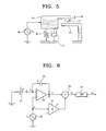
- FIG 5 is a view showing the variable capacitor of FIG 4;
- FIG 6 is a circuit diagram showing a second example of the apparatus for driving a MEMS structure and detecting the motion of the driven MEMS structure according to the embodiment of the present invention.
- FIG 7 is a view showing the variable capacitor of FIG 6.
- FIG 3 is a block diagram showing an apparatus for driving a MEMS structure and detecting motion of the driven MEMS structure according to an embodiment of the present invention.
- the apparatus for driving a MEMS structure and detecting motion of the driven MEMS structure comprises a driving signal generation part 20, a motion detection part 21, an amplification part 22, a gain adjustment part 24, a differential circuit part 25, and a motion signal detection part 26.
- the driving signal generation part 20 may be embodied as a voltage source or a current source for outputting a driving signal V s in a periodic square wave or sine wave form to drive the MEMS structure.
- the motion detection part 21 detects motion information of the MEMS structure driven in response to the driving signal V s and supplies a motion signal I.
- the motion signal I obtained by the motion detection part 21 contains the driving signal V s .
- the motion detection part 21 is embodied by a variable capacitor consisting of a movable electrode plate integrally formed with the MEMS structure and a fixed electrode.
- the MEMS structure, which is subjected to the motion detection, such as electrostatic accelerators, actuators, and gyroscopes has to be modeled by the variable capacitor. Accordingly, the detection of change in a capacitance of the variable capacitor enables obtaining the motion information of the MEMS structure.
- the amplification part 22 transforms the motion signal I in a current form supplied from the motion detection part 21 into an amplified motion signal V 1 in a voltage form and outputs the transformed signal.
- the amplification part 22 may be embodied by a charge amplifier constructed by the combination of an amplifier and a capacitor.
- the gain adjustment part 24 is connected to the motion detection part 21 in parallel, for amplifying the driving signal V s output from the driving signal generation part 20 by a predetermined gain.
- the gain adjustment part 24 may be embodied by the combination of an operational amplifier and a resistor or a capacitor connected to the operational amplifier in parallel, or may be embodied by a variable resistor or a multiplier.
- the differential circuit part 25 is supplied with the amplified motion signal V 1 including the driving signal and the driving signal amplified by the gain adjustment part 24, and performs addition and subtraction with respect to the signals.
- the gain adjustment 24 adjusts the gain to make the driving signal included in the amplified motion signal V 1 equal to the driving signal input into the differential circuit part 25 after passing through the gain adjustment part 24, in amplitude.
- the differential circuit part 25 is operated so that the two input driving signals are counterbalanced by each other. Accordingly, a motion signal V 2 output from the differential circuit part 25 excludes the driving signal V s .
- the motion signal V 2 supplied to the motion signal detection part 26 includes a signal corresponding to the change amount ( ⁇ C) of the capacitance, as well as a DC signal corresponding to a nominal capacitance C 0 and a second high frequency signal, it is necessary to remove these signals.
- the motion signal detection part 26 blocks these unnecessary signals and detects and outputs only the motion signal V out corresponding to the change amount ( ⁇ C) of the capacitance.
- FIG 4 is a circuit diagram showing a first example of an apparatus for driving a MEMS structure and detecting motion of the driven MEMS structure according to an embodiment of the preset invention.
- a driving signal V s output from a driving source 30 and having a predetermined frequency ⁇ is separated at a node 1 N 1 to be supplied to a variable capacitor 31 and a variable amplifier 34.
- variable capacitor 31 is embodied by a fixed electrode plate 41 and a movable electrode plate 45 integrally formed with a movable MEMS structure 44.
- the driving signal V s of the frequency ⁇ is supplied to the movable electrode plate 45, the MEMS structure 44 supported on a spring 42 and a damper 43 and the movable electrode plate 45 vibrate with the frequency ⁇ in response to the driving signal V s . That is, the motion of the movable electrode plate 45 causes the capacitance C (C 0 + ⁇ C) of the variable capacitor 31, which consists of the two electrode plates 41 and 45, to be changed. Information about the change in the capacitance C is output as a signal in a current form.
- the variable amplifier 34 amplifies the input driving signal V s by a predetermined gain to make the driving signal V s equal to the driving signal of the frequency ⁇ of the output signals V 1 in an amplitude and outputs the amplified signal to an adder 35.
- the adder 35 performs an operation to counterbalance the two input driving signals of the frequency ⁇ and output a signal V 2 to a band pass filter (BPF) 36.
- BPF band pass filter
- the band pass filter 36 selects and outputs only the motion signal V out of the frequency ⁇ among the input signals V 2 . Using the selected motion signal V out , information about the motion of the variable capacitor 31, i.e., the motion of the MEMS structure can be obtained.
- FIG 6 is a circuit diagram showing a second example of an apparatus for driving a MEMS structure and detecting motion of the driven MEMS structure according to an embodiment of the present invention.
- a driving signal V s output from a driving source 50 and having a predetermined frequency ⁇ is separated at a node 1 P 1 to be supplied to a positive terminal of an amplifier 52 and a variable amplifier 54.
- a variable capacitor 51 having one end connected to a grounded electrode.
- variable capacitor 51 is embodied by a fixed electrode plate 61 to be supplied with the driving signal V s and a movable electrode plate 65 integrally formed with a MEMS structure 64.
- the driving signal V s of the frequency ⁇ is supplied to the fixed electrode plate 61
- the MEMS structure 64 supported on a spring 62 and a damper 63 and the movable electrode plate 65 vibrate with the frequency ⁇ in response to the driving signal V s . That is, the motion of the movable electrode plate 65 causes a capacitance C (C 0 + ⁇ C ) of the variable capacitor 51 consisting of the two electrode plates 61 and 65 to be changed.
- Information about the change in the capacitance C is output as a signal i in a current form.
- an electrical potential at a node 2 P 2 becomes the driving signal V s and the current signal i flowing from the variable capacitor 51 to the node 2 P 2 is output to a capacitor C f 53.
- V 1 denotes an electrical potential at a node 3 P 3 .
- the variable amplifier 54 amplifies the input driving signal Vs by a predetermined gain to the amplitude of the driving signal of frequency ⁇ among the output signals V 1 , and outputs the amplified signal to an adder 55.
- the adder 55 performs an operation so that the two input driving signals of the frequency ⁇ are counterbalanced by each other, and outputs a signal V 2 to a band pass filter (BPF) 56.
- BPF band pass filter
- the band pass filter 56 selects and outputs only the motion signal V out of the frequency ⁇ of the input signals V 2 . Using the selected motion signal V out , information about the motion of the variable capacitor 51, i.e., the motion of the MEMS structure is obtained.
- Another embodiment of the invention includes a method for driving a MEMS (Micro Electro Mechanical System) structure and detecting motion of the driven MEMS structure using a single electrode.
- the method includes generating and outputting a first driving signal to drive the MEMS structure.
- the motion of the MEMS structure driven according to the first driving signal is detected with a variable capacitor and a motion current signal corresponding to the motion of the MEMS structure is outputted.
- the motion current signal is amplified and a motion voltage signal is outputted.
- the first driving signal input is amplified and a second driving signal amplified by a predetermined gain is outputted. Adding and subtracting operations with respect to the motion voltage signal and the second driving signal is performed and a motion signal without the second driving signal is outputted.
- a motion signal of a predetermined frequency is selected and outputted from the motion signal.
- variable capacitor includes a movable electrode plate integral to the MEMS structure and supplied with the first driving signal and a fixed electrode plate disposed opposite to the movable electrode plate and virtually grounded.
- the apparatus for driving the MEMS structure and detecting the motion of the driven MEMS structure is embodied by one single electrode, which reduces overall size of the MEMS structure and also increases voltage efficiency.
Abstract
Description
- This application claims the benefit of Korean Patent Application No. 2003-94617, filed on December 22, 2003, in the Korean Intellectual Property Office, the disclosure of which is incorporated herein by reference.
- The present invention relates to an apparatus and a method for driving a MEMS (Micro Electro Mechanical Systems) structure and detecting the motion of the driven MEMS structure.
- MEMS has realized the integration of mechanical components into microelectronic elements using semiconductor processes, and promises to revolutionize numerous industrial fields including electronics, mechanics, medical, and defense industries. MEMS makes it possible to realize machines and equipments having a hyperfine structure under several µm. Especially, sensors fabricated in a hyperfine structure through MEMS technology are embedded in compact devices such as a cellular phone and detect the mechanical motion in the range of several ten nm - several µm as an electronic signal of several pico F. The displacement of the MEMS structure is detected using the amount by which capacitance changes. A conventional apparatus for driving a MEMS structure and detecting the motion of the driven MEMS structure is described below.
- FIG 1 is a circuit diagram showing the conventional apparatus for driving a MEMS structure and detecting the motion of the driven MEMS structure. Referring to FIG 1, the apparatus comprises a
driving source 5, afirst variable capacitor 6a being supplied with a driving signal from thedriving source 5 to drive the MEMS structure, asecond variable capacitor 6b serially connected to thefirst variable capacitor 6a, for detecting the motion of the MEMS structure and supplying a motion signal, and an amplifyingcircuit 8 connected to thesecond variable capacitor 6b, for outputting an amplified voltage signal Vout with respect to an input signal in a current form. - FIG 2 is a view showing configurations of the first and the
second variable capacitors electrode plate 11a supplied with the driving signal, a second fixedelectrode plate 11b disposed apart from the first fixedelectrode plate 11b by a predetermined distance and opposite to the first fixedelectrode plate 11b, and amovable electrode plate 15 integrally formed with theMEMS structure 14, which is supported on aspring 12 and adamper 13 to be movable to a predetermined direction, and located between the first an second fixedelectrode plates variable capacitor 6a is embodied by the first fixedelectrode plate 11 a and themovable electrode plate 15, and thesecond variable capacitor 6b is embodied by themovable electrode plate 15 and the second fixedelectrode plate 11b. - In the conventional driving of the MEMS structure and detecting of the motion of the driven MEMS structure, it is necessary to comprise a driving electrode for driving the
MEMS structure 14 and a detecting electrode for detecting the motion of theMEMS structure 14, separately. Due to the addition of the detecting electrode which does not contribute to the driving of theMEMS structure 14, a problem of volume increase is created in the system that is required to be small-sized. - The present invention has been developed in order to solve the above problem in the related art. Accordingly, an aspect of the present invention is to provide an apparatus for driving a MEMS structure and detecting the motion of the driven MEMS structure using a single electrode.
- The above aspect is achieved by providing an apparatus for driving a MEMS structure and detecting motion of the driven MEMS structure using a single electrode, comprising: a driving signal generation part for generating and outputting a driving signal to drive the MEMS structure; a motion detection part configured by one single variable capacitor, for detecting the motion of the MEMS structure driven according to the driving signal and outputting a motion current signal corresponding to the motion of the MEMS structure; an amplification part for amplifying the motion current signal output from the motion detection part and outputting a motion voltage signal; a gain adjustment part for amplifying the driving signal input from the driving signal generation part and outputting a driving signal amplified by a predetermined gain; a differential circuit part for performing adding and subtracting operations with respect to the respective signals output from the amplifying and the gain adjustment part and outputting a motion signal without the driving signal by which the driving signal is compensated; and a motion signal detection part for selecting and outputting a motion signal of a predetermined frequency out of the motion signals output from the differential circuit part.
- The variable capacitor may be configured by a movable electrode plate integrally formed with the MEMS structure and supplied with the driving signal and a fixed electrode plate disposed opposite to the movable electrode plate and virtually grounded.
- The amplification part may comprise: an amplifier having a negative input terminal connected to the fixed electrode plate, a positive terminal connected to a grounded electrode, and an output terminal; and a first capacitor connected to the amplifier in parallel.
- The variable capacitor may be configured by a movable electrode plate integrally formed with the MEMS structure, and a fixed electrode plate disposed opposite to the movable electrode plate, supplied with the driving signal, and virtually grounded.
- The amplification part may comprise: an amplifier having a negative input terminal connected to the fixed electrode plate, a positive input terminal connected to the driving signal generation part, and an output terminal; and a second capacitor connected to the amplifier in parallel.
- The motion signal detection part may be a band pass filter, and the gain adjustment part may be an amplifier for amplifying the driving signal to the amplitude of the driving signal included in the motion signal output from the amplification part.
- Another aspect of the invention includes a method for achieving the above.
- The above aspect and other advantages of the present invention will be more apparent by describing embodiments of the present invention with reference to the accompanying drawings, in which:
- FIG 1 is a circuit diagram showing a conventional apparatus for driving a MEMS structure and detecting motion of the driven MEMS structure;
- FIG 2 is a view showing the configurations of the first and the second variable capacitors of FIG 1;
- FIG 3 is a block diagram showing an apparatus for driving a MEMS structure and detecting motion of the driven MEMS structure according to an embodiment of the present invention;
- FIG 4 is a circuit diagram showing a first example of the apparatus for driving a MEMS structure and detecting the motion of the driven MEMS structure according to the embodiment of the present invention;
- FIG 5 is a view showing the variable capacitor of FIG 4;
- FIG 6 is a circuit diagram showing a second example of the apparatus for driving a MEMS structure and detecting the motion of the driven MEMS structure according to the embodiment of the present invention; and
- FIG 7 is a view showing the variable capacitor of FIG 6.
- Hereinafter, the present invention will be described in detail with reference to the accompanying drawings.
- FIG 3 is a block diagram showing an apparatus for driving a MEMS structure and detecting motion of the driven MEMS structure according to an embodiment of the present invention. Referring to FIG 3, the apparatus for driving a MEMS structure and detecting motion of the driven MEMS structure comprises a driving
signal generation part 20, amotion detection part 21, anamplification part 22, again adjustment part 24, adifferential circuit part 25, and a motionsignal detection part 26. - The driving
signal generation part 20 may be embodied as a voltage source or a current source for outputting a driving signal Vs in a periodic square wave or sine wave form to drive the MEMS structure. - The
motion detection part 21 detects motion information of the MEMS structure driven in response to the driving signal Vs and supplies a motion signal I. The motion signal I obtained by themotion detection part 21 contains the driving signal Vs. Themotion detection part 21 is embodied by a variable capacitor consisting of a movable electrode plate integrally formed with the MEMS structure and a fixed electrode. The MEMS structure, which is subjected to the motion detection, such as electrostatic accelerators, actuators, and gyroscopes has to be modeled by the variable capacitor. Accordingly, the detection of change in a capacitance of the variable capacitor enables obtaining the motion information of the MEMS structure. - The
amplification part 22 transforms the motion signal I in a current form supplied from themotion detection part 21 into an amplified motion signal V1 in a voltage form and outputs the transformed signal. Theamplification part 22 may be embodied by a charge amplifier constructed by the combination of an amplifier and a capacitor. - The
gain adjustment part 24 is connected to themotion detection part 21 in parallel, for amplifying the driving signal Vs output from the drivingsignal generation part 20 by a predetermined gain. Thegain adjustment part 24 may be embodied by the combination of an operational amplifier and a resistor or a capacitor connected to the operational amplifier in parallel, or may be embodied by a variable resistor or a multiplier. - The
differential circuit part 25 is supplied with the amplified motion signal V1 including the driving signal and the driving signal amplified by thegain adjustment part 24, and performs addition and subtraction with respect to the signals. Here, thegain adjustment 24 adjusts the gain to make the driving signal included in the amplified motion signal V1 equal to the driving signal input into thedifferential circuit part 25 after passing through thegain adjustment part 24, in amplitude. Also, thedifferential circuit part 25 is operated so that the two input driving signals are counterbalanced by each other. Accordingly, a motion signal V2 output from thedifferential circuit part 25 excludes the driving signal Vs. - Because the motion signal V2 supplied to the motion
signal detection part 26 includes a signal corresponding to the change amount (ΔC) of the capacitance, as well as a DC signal corresponding to a nominal capacitance C0 and a second high frequency signal, it is necessary to remove these signals. The motionsignal detection part 26 blocks these unnecessary signals and detects and outputs only the motion signal Vout corresponding to the change amount (ΔC) of the capacitance. - FIG 4 is a circuit diagram showing a first example of an apparatus for driving a MEMS structure and detecting motion of the driven MEMS structure according to an embodiment of the preset invention. Referring to FIG 4, a driving signal Vs output from a
driving source 30 and having a predetermined frequency ω is separated at a node 1 N1 to be supplied to avariable capacitor 31 and avariable amplifier 34. - The configuration of the
variable capacitor 31 is described below with reference to the FIG 5. Thevariable capacitor 31 is embodied by afixed electrode plate 41 and amovable electrode plate 45 integrally formed with amovable MEMS structure 44. When the driving signal Vs of the frequency ω is supplied to themovable electrode plate 45, theMEMS structure 44 supported on aspring 42 and adamper 43 and themovable electrode plate 45 vibrate with the frequency ω in response to the driving signal Vs. That is, the motion of themovable electrode plate 45 causes the capacitance C (C0 +ΔC) of thevariable capacitor 31, which consists of the twoelectrode plates - Meanwhile, referring back to FIG 4, since an
amplifier 32 has a positive terminal connected to a grounded electrode, an electrical potential at a node 2 N2 becomes 0 and a current signal flowing from thevariable capacitor 31 to the node 2 N2 is output to a capacitor Cf. This is expressed by the following equation 1:equation 1 makes the following equation 2. That is, the amplified output signal V1 is obtained by the following equation 2:V - The
variable amplifier 34 amplifies the input driving signal Vs by a predetermined gain to make the driving signal Vs equal to the driving signal of the frequency ω of the output signals V1 in an amplitude and outputs the amplified signal to anadder 35. Theadder 35 performs an operation to counterbalance the two input driving signals of the frequency ω and output a signal V2 to a band pass filter (BPF) 36. Theband pass filter 36 selects and outputs only the motion signal Vout of the frequency ω among the input signals V2. Using the selected motion signal Vout, information about the motion of thevariable capacitor 31, i.e., the motion of the MEMS structure can be obtained. - FIG 6 is a circuit diagram showing a second example of an apparatus for driving a MEMS structure and detecting motion of the driven MEMS structure according to an embodiment of the present invention. Referring to FIG 6, a driving signal Vs output from a driving
source 50 and having a predetermined frequency ω is separated at a node 1 P1 to be supplied to a positive terminal of anamplifier 52 and avariable amplifier 54. To a negative terminal of theamplifier 52 is connected avariable capacitor 51 having one end connected to a grounded electrode. - The configuration of the
variable capacitor 51 is described below with reference to FIG 7. Thevariable capacitor 51 is embodied by a fixedelectrode plate 61 to be supplied with the driving signal Vs and amovable electrode plate 65 integrally formed with aMEMS structure 64. When the driving signal Vs of the frequency ω is supplied to the fixedelectrode plate 61, theMEMS structure 64 supported on aspring 62 and adamper 63 and themovable electrode plate 65 vibrate with the frequency ω in response to the driving signal Vs. That is, the motion of themovable electrode plate 65 causes a capacitance C (C0 + ΔC ) of thevariable capacitor 51 consisting of the twoelectrode plates - Meanwhile, referring back to FIG 6, an electrical potential at a node 2 P2 becomes the driving signal Vs and the current signal i flowing from the
variable capacitor 51 to the node 2 P2 is output to acapacitor C f 53. This is expressed by the following equation:V - The
variable amplifier 54 amplifies the input driving signal Vs by a predetermined gain to the amplitude of the driving signal of frequency ω among the output signals V1, and outputs the amplified signal to anadder 55. Theadder 55 performs an operation so that the two input driving signals of the frequency ω are counterbalanced by each other, and outputs a signal V2 to a band pass filter (BPF) 56. Theband pass filter 56 selects and outputs only the motion signal Vout of the frequency ω of the input signals V2. Using the selected motion signal Vout, information about the motion of thevariable capacitor 51, i.e., the motion of the MEMS structure is obtained. - Another embodiment of the invention includes a method for driving a MEMS (Micro Electro Mechanical System) structure and detecting motion of the driven MEMS structure using a single electrode. The method includes generating and outputting a first driving signal to drive the MEMS structure. The motion of the MEMS structure driven according to the first driving signal is detected with a variable capacitor and a motion current signal corresponding to the motion of the MEMS structure is outputted. The motion current signal is amplified and a motion voltage signal is outputted. The first driving signal input is amplified and a second driving signal amplified by a predetermined gain is outputted. Adding and subtracting operations with respect to the motion voltage signal and the second driving signal is performed and a motion signal without the second driving signal is outputted. A motion signal of a predetermined frequency is selected and outputted from the motion signal.
- Yet another embodiment of the invention includes the embodiment described above wherein the variable capacitor includes a movable electrode plate integral to the MEMS structure and supplied with the first driving signal and a fixed electrode plate disposed opposite to the movable electrode plate and virtually grounded.
- As described above, according to the present invention, the apparatus for driving the MEMS structure and detecting the motion of the driven MEMS structure is embodied by one single electrode, which reduces overall size of the MEMS structure and also increases voltage efficiency.
- The foregoing embodiment and advantages are merely exemplary and are not to be construed as limiting the present invention. The description of the present invention is intended to be illustrative, and not to limit the scope of the claims. Many alternatives, modifications, and variations will be apparent to those skilled in the art. In the claims, means-plus-function clauses are intended to cover the structures described herein as performing the recited function and not only structural equivalents but also equivalent structures.
Claims (9)
- An apparatus for driving a MEMS (Micro Electro Mechanical System) structure and detecting motion of the driven MEMS structure using a single electrode, comprising:a driving signal generation part for generating and outputting a first driving signal to drive the MEMS structure;a motion detection part comprising a variable capacitor, for detecting the motion of the MEMS structure driven according to the first driving signal and outputting a motion current signal corresponding to the motion of the MEMS structure;an amplification part for amplifying the motion current signal output from the motion detection part and outputting a motion voltage signal;a gain adjustment part for amplifying the first driving signal input from the driving signal generation part and outputting a second driving signal amplified by a predetermined gain;a differential circuit part for performing adding and subtracting operations with respect to the motion voltage signal output from the amplifying part and the second driving signal output from the gain adjustment part and outputting a motion signal without the second driving signal; anda motion signal detection part for selecting and outputting a motion signal of a predetermined frequency out of the motion signal output from the differential circuit part.
- The apparatus as claimed in claim 1, wherein the variable capacitor comprises a movable electrode plate integral to the MEMS structure and supplied with the first driving signal and a fixed electrode plate disposed opposite to the movable electrode plate and virtually grounded.
- The apparatus as claimed in claim 2, wherein the amplification part comprises:an amplifier having a negative input terminal connected to the fixed electrode plate, a positive terminal connected to a grounded electrode, and an output terminal; anda first capacitor connected to the amplifier in parallel.
- The apparatus as claimed in claim 1, wherein the variable capacitor comprises a movable electrode plate integral to the MEMS structure and grounded, and a fixed electrode plate disposed opposite to the movable electrode plate and supplied with the first driving signal.
- The apparatus as claimed in claim 4, wherein the amplification part comprises:an amplifier having a negative input terminal connected to the fixed electrode plate, a positive input terminal connected to the driving signal generation part, and an output terminal; anda second capacitor connected to the amplifier in parallel.
- The apparatus as claimed in claim 1, wherein the motion signal detection part is a band pass filter.
- The apparatus as claimed in claim 1, wherein the gain adjustment part is an amplifier for amplifying the first driving signal to an amplitude of a third driving signal included in the motion signal output from the amplification part.
- A method for driving a MEMS (Micro Electro Mechanical System) structure and detecting motion of the driven MEMS structure using a single electrode, comprising:generating and outputting a first driving signal to drive the MEMS structure;detecting the motion of the MEMS structure driven according to the first driving signal with a variable capacitor and outputting a motion current signal corresponding to the motion of the MEMS structure;amplifying the motion current signal and outputting a motion voltage signal;amplifying the first driving signal input and outputting a second driving signal amplified by a predetermined gain;performing adding and subtracting operations with respect to the motion voltage signal and the second driving signal and outputting a motion signal without the second driving signal; andselecting and outputting a motion signal of a predetermined frequency from the motion signal.
- The method as claimed in claim 8, wherein the variable capacitor comprises a movable electrode plate integral to the MEMS structure and supplied with the first driving signal and a fixed electrode plate disposed opposite to the movable electrode plate and virtually grounded.
Applications Claiming Priority (2)
| Application Number | Priority Date | Filing Date | Title |
|---|---|---|---|
| KR2003094617 | 2003-12-22 | ||
| KR1020030094617A KR100565800B1 (en) | 2003-12-22 | 2003-12-22 | Apparatus for driving and motion detection of MEMS structure using single electrode |
Publications (2)
| Publication Number | Publication Date |
|---|---|
| EP1548403A1 true EP1548403A1 (en) | 2005-06-29 |
| EP1548403B1 EP1548403B1 (en) | 2015-03-04 |
Family
ID=34545887
Family Applications (1)
| Application Number | Title | Priority Date | Filing Date |
|---|---|---|---|
| EP04029996.8A Expired - Fee Related EP1548403B1 (en) | 2003-12-22 | 2004-12-17 | Apparatus and method for driving mems structure and detecting motion of the driven mems structure using a single electrode |
Country Status (4)
| Country | Link |
|---|---|
| US (1) | US7178397B2 (en) |
| EP (1) | EP1548403B1 (en) |
| JP (1) | JP4180047B2 (en) |
| KR (1) | KR100565800B1 (en) |
Cited By (1)
| Publication number | Priority date | Publication date | Assignee | Title |
|---|---|---|---|---|
| CN104390639A (en) * | 2014-10-31 | 2015-03-04 | 中国人民解放军国防科学技术大学 | Method and device for improving scale factor stability of micromechanical gyroscope |
Families Citing this family (13)
| Publication number | Priority date | Publication date | Assignee | Title |
|---|---|---|---|---|
| JP4919819B2 (en) * | 2007-01-24 | 2012-04-18 | 富士通株式会社 | Micromachine device drive control method and apparatus |
| JP4610576B2 (en) | 2007-03-30 | 2011-01-12 | 富士通株式会社 | Micromachine device drive control method and apparatus |
| US8368490B2 (en) | 2008-12-18 | 2013-02-05 | Analog Devices, Inc. | Micro-electro-mechanical switch beam construction with minimized beam distortion and method for constructing |
| US8294539B2 (en) * | 2008-12-18 | 2012-10-23 | Analog Devices, Inc. | Micro-electro-mechanical switch beam construction with minimized beam distortion and method for constructing |
| US8291765B2 (en) * | 2009-05-04 | 2012-10-23 | Raytheon Company | Carrier modulating accelerometer |
| US8102637B2 (en) * | 2009-07-22 | 2012-01-24 | Analog Devices, Inc. | Control techniques for electrostatic microelectromechanical (MEM) structure |
| US8587328B2 (en) * | 2009-08-25 | 2013-11-19 | Analog Devices, Inc. | Automatic characterization of an actuator based on capacitance measurement |
| JP5538831B2 (en) * | 2009-11-17 | 2014-07-02 | キヤノン株式会社 | Control device and control method of electromechanical transducer, and measurement system |
| JP5722681B2 (en) * | 2011-03-30 | 2015-05-27 | 株式会社ダイヘン | Simulated load device |
| CN103105531B (en) * | 2013-01-18 | 2015-09-30 | 东南大学 | The online microwave frequency detector of microelectron-mechanical and detection method thereof |
| JP6197323B2 (en) * | 2013-03-22 | 2017-09-20 | セイコーエプソン株式会社 | Detection device, sensor, gyro sensor, electronic device, and moving object |
| FR3005204A1 (en) * | 2013-04-30 | 2014-10-31 | St Microelectronics Rousset | INTEGRATED SWITCHABLE CAPACITIVE DEVICE |
| KR101764338B1 (en) | 2015-07-14 | 2017-08-03 | 주식회사 인디고엔터테인먼트 | Treadmill motion tracking device of chair type |
Citations (5)
| Publication number | Priority date | Publication date | Assignee | Title |
|---|---|---|---|---|
| US5349855A (en) * | 1992-04-07 | 1994-09-27 | The Charles Stark Draper Laboratory, Inc. | Comb drive micromechanical tuning fork gyro |
| US5604309A (en) * | 1994-03-28 | 1997-02-18 | The Charles Stark Draper Laboratory, Inc. | Electronics for Coriolis force and other sensors |
| US6079272A (en) * | 1997-08-13 | 2000-06-27 | California Institute Of Technology | Gyroscopes and compensation |
| EP1160574A1 (en) * | 2000-06-02 | 2001-12-05 | Murata Manufacturing Co., Ltd. | Capacitance-type external-force detecting device with improved sensitivity |
| US20020059829A1 (en) * | 2000-10-24 | 2002-05-23 | Minekazu Sakai | Semiconductor dynamic quantity sensor for detecting dynamic quantity in two axes with X-shaped mass portion |
Family Cites Families (5)
| Publication number | Priority date | Publication date | Assignee | Title |
|---|---|---|---|---|
| JPH1073437A (en) * | 1996-08-30 | 1998-03-17 | Fujitsu Ltd | Oscillation gyro and detection circuit thereof |
| US5986497A (en) * | 1997-05-16 | 1999-11-16 | Mitsubishi Denki Kabushiki Kaisha | Interface circuit for capacitive sensor |
| US6253612B1 (en) * | 1998-06-05 | 2001-07-03 | Integrated Micro Instruments, Inc. | Generation of mechanical oscillation applicable to vibratory rate gyroscopes |
| US6731121B1 (en) * | 1999-10-15 | 2004-05-04 | Microsensors Corp. | Highly configurable capacitive transducer interface circuit |
| US6393914B1 (en) * | 2001-02-13 | 2002-05-28 | Delphi Technologies, Inc. | Angular accelerometer |
-
2003
- 2003-12-22 KR KR1020030094617A patent/KR100565800B1/en not_active IP Right Cessation
-
2004
- 2004-12-17 EP EP04029996.8A patent/EP1548403B1/en not_active Expired - Fee Related
- 2004-12-21 JP JP2004369203A patent/JP4180047B2/en not_active Expired - Fee Related
- 2004-12-22 US US11/018,830 patent/US7178397B2/en not_active Expired - Fee Related
Patent Citations (5)
| Publication number | Priority date | Publication date | Assignee | Title |
|---|---|---|---|---|
| US5349855A (en) * | 1992-04-07 | 1994-09-27 | The Charles Stark Draper Laboratory, Inc. | Comb drive micromechanical tuning fork gyro |
| US5604309A (en) * | 1994-03-28 | 1997-02-18 | The Charles Stark Draper Laboratory, Inc. | Electronics for Coriolis force and other sensors |
| US6079272A (en) * | 1997-08-13 | 2000-06-27 | California Institute Of Technology | Gyroscopes and compensation |
| EP1160574A1 (en) * | 2000-06-02 | 2001-12-05 | Murata Manufacturing Co., Ltd. | Capacitance-type external-force detecting device with improved sensitivity |
| US20020059829A1 (en) * | 2000-10-24 | 2002-05-23 | Minekazu Sakai | Semiconductor dynamic quantity sensor for detecting dynamic quantity in two axes with X-shaped mass portion |
Cited By (2)
| Publication number | Priority date | Publication date | Assignee | Title |
|---|---|---|---|---|
| CN104390639A (en) * | 2014-10-31 | 2015-03-04 | 中国人民解放军国防科学技术大学 | Method and device for improving scale factor stability of micromechanical gyroscope |
| CN104390639B (en) * | 2014-10-31 | 2017-10-03 | 中国人民解放军国防科学技术大学 | Scale factor stability method for improving and device for micromechanical gyro |
Also Published As
| Publication number | Publication date |
|---|---|
| JP2005177985A (en) | 2005-07-07 |
| EP1548403B1 (en) | 2015-03-04 |
| US7178397B2 (en) | 2007-02-20 |
| US20050132806A1 (en) | 2005-06-23 |
| KR100565800B1 (en) | 2006-03-29 |
| JP4180047B2 (en) | 2008-11-12 |
| KR20050063238A (en) | 2005-06-28 |
Similar Documents
| Publication | Publication Date | Title |
|---|---|---|
| EP1548403A1 (en) | Apparatus and method for driving mems structure and detecting motion of the driven mems structure using a single electrode | |
| US10523162B2 (en) | Split signal differential MEMS microphone | |
| JP5319368B2 (en) | Amplifier circuit for condenser microphone | |
| EP2178208A2 (en) | Systems and methods to overcome DC offsets in amplifiers used to start resonant micro-electro mechanical systems | |
| EP3694223A1 (en) | Sensor arrangement and method for providing a sensor signal | |
| EP1988366A1 (en) | Readout-interface circuit for a capacitive microelectromechanical sensor, and corresponding sensor | |
| KR101077383B1 (en) | Inertia force sensor | |
| JP2005192181A (en) | Capacitor microphone for smd | |
| JP2007256233A5 (en) | ||
| JP2006229336A (en) | Capacitive microphone | |
| US10656006B2 (en) | Sensing circuit comprising an amplifying circuit and an amplifying circuit | |
| JP2008281555A (en) | Methods and systems for driver noise reduction in mems gyro | |
| CN100387946C (en) | Device for operating a vibrating unit of a vibration resonator | |
| US9201165B2 (en) | Detection circuit | |
| JP2017156314A (en) | Drive circuit, angular velocity detection device, electronic apparatus and mobile body | |
| JP2006352533A (en) | Portable terminal apparatus | |
| US10264361B2 (en) | Transducer with a high sensitivity | |
| KR101493510B1 (en) | MEMS microphone system | |
| CN110740411A (en) | Interface circuit, micro-electromechanical acoustic sensor, and driving method of interface circuit | |
| WO2007111611A1 (en) | Methods and apparatus for differential signaling using absolute pressure sensors | |
| EP3324647A1 (en) | An assembly and an amplifier for use in the assembly | |
| Dean et al. | Experimental validation and testing of components for active damping control for micromachined mechanical vibration isolation filters using electrostatic actuation |
Legal Events
| Date | Code | Title | Description |
|---|---|---|---|
| PUAI | Public reference made under article 153(3) epc to a published international application that has entered the european phase |
Free format text: ORIGINAL CODE: 0009012 |
|
| 17P | Request for examination filed |
Effective date: 20041217 |
|
| AK | Designated contracting states |
Kind code of ref document: A1 Designated state(s): AT BE BG CH CY CZ DE DK EE ES FI FR GB GR HU IE IS IT LI LT LU MC NL PL PT RO SE SI SK TR |
|
| AX | Request for extension of the european patent |
Extension state: AL BA HR LV MK YU |
|
| AKX | Designation fees paid |
Designated state(s): DE FR GB |
|
| 17Q | First examination report despatched |
Effective date: 20060630 |
|
| RAP1 | Party data changed (applicant data changed or rights of an application transferred) |
Owner name: SAMSUNG ELECTRONICS CO., LTD. |
|
| REG | Reference to a national code |
Ref country code: DE Ref legal event code: R079 Ref document number: 602004046719 Country of ref document: DE Free format text: PREVIOUS MAIN CLASS: G01C0019560000 Ipc: G01C0019577600 |
|
| RIC1 | Information provided on ipc code assigned before grant |
Ipc: G01C 19/5776 20120101AFI20130919BHEP |
|
| GRAP | Despatch of communication of intention to grant a patent |
Free format text: ORIGINAL CODE: EPIDOSNIGR1 |
|
| INTG | Intention to grant announced |
Effective date: 20140624 |
|
| GRAP | Despatch of communication of intention to grant a patent |
Free format text: ORIGINAL CODE: EPIDOSNIGR1 |
|
| INTG | Intention to grant announced |
Effective date: 20141024 |
|
| GRAS | Grant fee paid |
Free format text: ORIGINAL CODE: EPIDOSNIGR3 |
|
| GRAA | (expected) grant |
Free format text: ORIGINAL CODE: 0009210 |
|
| AK | Designated contracting states |
Kind code of ref document: B1 Designated state(s): DE FR GB |
|
| REG | Reference to a national code |
Ref country code: GB Ref legal event code: FG4D |
|
| REG | Reference to a national code |
Ref country code: DE Ref legal event code: R096 Ref document number: 602004046719 Country of ref document: DE Effective date: 20150416 |
|
| REG | Reference to a national code |
Ref country code: DE Ref legal event code: R097 Ref document number: 602004046719 Country of ref document: DE |
|
| PLBE | No opposition filed within time limit |
Free format text: ORIGINAL CODE: 0009261 |
|
| STAA | Information on the status of an ep patent application or granted ep patent |
Free format text: STATUS: NO OPPOSITION FILED WITHIN TIME LIMIT |
|
| 26N | No opposition filed |
Effective date: 20151207 |
|
| REG | Reference to a national code |
Ref country code: DE Ref legal event code: R119 Ref document number: 602004046719 Country of ref document: DE |
|
| GBPC | Gb: european patent ceased through non-payment of renewal fee |
Effective date: 20151217 |
|
| REG | Reference to a national code |
Ref country code: FR Ref legal event code: ST Effective date: 20160831 |
|
| PG25 | Lapsed in a contracting state [announced via postgrant information from national office to epo] |
Ref country code: GB Free format text: LAPSE BECAUSE OF NON-PAYMENT OF DUE FEES Effective date: 20151217 Ref country code: DE Free format text: LAPSE BECAUSE OF NON-PAYMENT OF DUE FEES Effective date: 20160701 |
|
| PG25 | Lapsed in a contracting state [announced via postgrant information from national office to epo] |
Ref country code: FR Free format text: LAPSE BECAUSE OF NON-PAYMENT OF DUE FEES Effective date: 20151231 |