EP1548244A1 - Assembly device of support mat and for ceramic catalyst carrier - Google Patents
Assembly device of support mat and for ceramic catalyst carrier Download PDFInfo
- Publication number
- EP1548244A1 EP1548244A1 EP04293134A EP04293134A EP1548244A1 EP 1548244 A1 EP1548244 A1 EP 1548244A1 EP 04293134 A EP04293134 A EP 04293134A EP 04293134 A EP04293134 A EP 04293134A EP 1548244 A1 EP1548244 A1 EP 1548244A1
- Authority
- EP
- European Patent Office
- Prior art keywords
- support mat
- catalyst carrier
- pressing
- ceramic catalyst
- unit
- Prior art date
- Legal status (The legal status is an assumption and is not a legal conclusion. Google has not performed a legal analysis and makes no representation as to the accuracy of the status listed.)
- Granted
Links
Images





Classifications
-
- B—PERFORMING OPERATIONS; TRANSPORTING
- B21—MECHANICAL METAL-WORKING WITHOUT ESSENTIALLY REMOVING MATERIAL; PUNCHING METAL
- B21D—WORKING OR PROCESSING OF SHEET METAL OR METAL TUBES, RODS OR PROFILES WITHOUT ESSENTIALLY REMOVING MATERIAL; PUNCHING METAL
- B21D53/00—Making other particular articles
- B21D53/88—Making other particular articles other parts for vehicles, e.g. cowlings, mudguards
-
- F—MECHANICAL ENGINEERING; LIGHTING; HEATING; WEAPONS; BLASTING
- F01—MACHINES OR ENGINES IN GENERAL; ENGINE PLANTS IN GENERAL; STEAM ENGINES
- F01N—GAS-FLOW SILENCERS OR EXHAUST APPARATUS FOR MACHINES OR ENGINES IN GENERAL; GAS-FLOW SILENCERS OR EXHAUST APPARATUS FOR INTERNAL-COMBUSTION ENGINES
- F01N13/00—Exhaust or silencing apparatus characterised by constructional features
- F01N13/18—Construction facilitating manufacture, assembly, or disassembly
-
- F—MECHANICAL ENGINEERING; LIGHTING; HEATING; WEAPONS; BLASTING
- F01—MACHINES OR ENGINES IN GENERAL; ENGINE PLANTS IN GENERAL; STEAM ENGINES
- F01N—GAS-FLOW SILENCERS OR EXHAUST APPARATUS FOR MACHINES OR ENGINES IN GENERAL; GAS-FLOW SILENCERS OR EXHAUST APPARATUS FOR INTERNAL-COMBUSTION ENGINES
- F01N3/00—Exhaust or silencing apparatus having means for purifying, rendering innocuous, or otherwise treating exhaust
- F01N3/08—Exhaust or silencing apparatus having means for purifying, rendering innocuous, or otherwise treating exhaust for rendering innocuous
- F01N3/10—Exhaust or silencing apparatus having means for purifying, rendering innocuous, or otherwise treating exhaust for rendering innocuous by thermal or catalytic conversion of noxious components of exhaust
- F01N3/24—Exhaust or silencing apparatus having means for purifying, rendering innocuous, or otherwise treating exhaust for rendering innocuous by thermal or catalytic conversion of noxious components of exhaust characterised by constructional aspects of converting apparatus
- F01N3/28—Construction of catalytic reactors
- F01N3/2839—Arrangements for mounting catalyst support in housing, e.g. with means for compensating thermal expansion or vibration
- F01N3/2853—Arrangements for mounting catalyst support in housing, e.g. with means for compensating thermal expansion or vibration using mats or gaskets between catalyst body and housing
-
- F—MECHANICAL ENGINEERING; LIGHTING; HEATING; WEAPONS; BLASTING
- F01—MACHINES OR ENGINES IN GENERAL; ENGINE PLANTS IN GENERAL; STEAM ENGINES
- F01N—GAS-FLOW SILENCERS OR EXHAUST APPARATUS FOR MACHINES OR ENGINES IN GENERAL; GAS-FLOW SILENCERS OR EXHAUST APPARATUS FOR INTERNAL-COMBUSTION ENGINES
- F01N2330/00—Structure of catalyst support or particle filter
- F01N2330/06—Ceramic, e.g. monoliths
-
- F—MECHANICAL ENGINEERING; LIGHTING; HEATING; WEAPONS; BLASTING
- F01—MACHINES OR ENGINES IN GENERAL; ENGINE PLANTS IN GENERAL; STEAM ENGINES
- F01N—GAS-FLOW SILENCERS OR EXHAUST APPARATUS FOR MACHINES OR ENGINES IN GENERAL; GAS-FLOW SILENCERS OR EXHAUST APPARATUS FOR INTERNAL-COMBUSTION ENGINES
- F01N2350/00—Arrangements for fitting catalyst support or particle filter element in the housing
- F01N2350/02—Fitting ceramic monoliths in a metallic housing
- F01N2350/04—Fitting ceramic monoliths in a metallic housing with means compensating thermal expansion
-
- Y—GENERAL TAGGING OF NEW TECHNOLOGICAL DEVELOPMENTS; GENERAL TAGGING OF CROSS-SECTIONAL TECHNOLOGIES SPANNING OVER SEVERAL SECTIONS OF THE IPC; TECHNICAL SUBJECTS COVERED BY FORMER USPC CROSS-REFERENCE ART COLLECTIONS [XRACs] AND DIGESTS
- Y10—TECHNICAL SUBJECTS COVERED BY FORMER USPC
- Y10T—TECHNICAL SUBJECTS COVERED BY FORMER US CLASSIFICATION
- Y10T29/00—Metal working
- Y10T29/49—Method of mechanical manufacture
- Y10T29/49345—Catalytic device making
Definitions
- the present invention relates to an assembly device automatically assembling a support mat to a ceramic catalyst carrier used in an exhaust system of a combustion engine of a motor vehicle, and others.
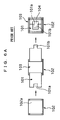
- FIG. 6A shows a process chart illustrating plane viewed states of the support mat 101 and the ceramic catalyst carrier 103 in three steps of an assembly procedure of them
- FIG. 6B shows a process chart illustrating front viewed states of them corresponding to the steps of FIG. 6A.
- the support mat 101 is assembled to a ceramic catalyst carrier 103 by using a jig 102 having a recess 102 with a semicircular cross section. Their assembly is performed by the following procedure. First, a rectangular metal plate to be the support mat 101 and the ceramic catalyst carrier 103 are prepared. This support mat 101 is formed to have a main body, and engagement portions consisting of a depression 101 a and a projection 101b that are provided in the main body at both end portions in a winding direction of thereof, respectively, and can be fitted with each other.
- the above formed support mat 101 is placed on the jig 102, and then the ceramic catalyst carrier 103 is pushed into the recess 102a of the jig 102, pressing the support mat 101 toward the recess 102 to deform a intermediate portion of the support mat, so that the intermediate portion of the support mat 101 is formed to curve along an arc-shaped bottom surface of the ceramic catalyst carrier 103. Then, the both end portions of the support mat 101, which are brought into a substantially perpendicularly standing state when the ceramic catalyst carrier 103 is pushed into the recess 102a, are pressed from both side portions thereof to approach each other so that the both end portions are curved along an arc-shaped upper surface of the ceramic catalyst carrier 103.
- An adhesive seal 104 is pasted on the engagement portions where the depression 101a and the projection 101b are engaged with each other, to thereby tentatively join the both end portions of the support mat 101. Then, the ceramic catalyst carrier 103 having the support mat 101 assembled around the outer periphery thereof is taken out of the recess 102a of the jib 102. All these processes have been manually carried out.
- An assembly device of a support mat for a ceramic catalyst carrier of the present invention includes: a base capable of holding a support mat in a flat plate shape substantially horizontally, the support mat having in both end portions a depression and a projection engageable with the depression; a shaping die provided on an intermediate portion of the base and having a recess that has a shape substantially fitting a semicircular bottom surface of the ceramic catalyst carrier; a push-in unit capable of pushing the ceramic catalyst carrier together with the support mat into the recess of the shaping die; a first pressing unit and a second pressing unit that press both end portions of the support mat from side faces so as to curve the both end portions of the support mat along an arc-shaped upper surface of the catalyst carrier; and a push-up unit provided on a bottom of the recess of the shaping die and capable of pushing up the ceramic catalyst carrier together with the support mat.
- the assembly device of the support mat for the ceramic catalyst carrier of the present invention assembles the support mat to the ceramic catalyst carrier, for example, in the following order.
- the assembly device of the support mat for the ceramic catalyst carrier it is possible to automate many assembly processes and to enhance positioning accuracy in assembling the support mat to the ceramic catalyst carrier, thereby preventing poor conditions that may possibly occur when the assembled body is press-fitted into a container constituting part of an exhaust passage.
- the support mat has in the both end portions thereof, respectively, a depression and a projection engageable with the depression.
- This engagement prevents misalignment in a latitudinal direction of the support mat of the engagement portions of the depression and the projection.
- the assembly devices further comprises an automatic tape feeder to feed an adhesive tape to an upper surface of one end portion of the base.
- This automatically tape feeding enables the adhesive tape to be arranged at the desired position of the base without undesirable variation.
- one of the first pressing unit and the second pressing unit that is to press one of the end portions of the support mat where the adhesive tape is not pasted is driven before the other one of the first and second pressing units is driven.
- This pressing brings a certain stick of the adhesive tape to the upper surfaces of the engagement portions of the depression and the projection.
- the assembly device further comprises a tape/support mat pressing unit that presses the other end portion of the support mat toward the adhesive tape while the other end portion of the support mat is placed on an upper surface of the adhesive tape, thereby sticking the adhesive tape to the other end portion.
- a tape/support mat pressing unit that presses the other end portion of the support mat toward the adhesive tape while the other end portion of the support mat is placed on an upper surface of the adhesive tape, thereby sticking the adhesive tape to the other end portion.
- This pressing brings a certain stick of the adhesive tape to the other end portion of the support mat.
- the push-in unit is composed of: a tool base provided above the shaping die and driven by a first actuator to be vertically movable; and a push-in device provided in the tool base and driven by a second actuator to be capable of pushing the ceramic catalyst carrier together with the support mat into the recess of the shaping die; and the first pressing unit and the second pressing unit are provided on the tool base.
- the assembly device further comprises a plurality of first pressing pieces and at least one second pressing piece that are integrally provided in tip portions of the first pressing unit and the second pressing unit respectively: the first pressing pieces covering areas of an upper surface excluding the depression in the depression-side end portion of the support mat; and the second pressing piece covering an area of the upper surface corresponding to the projection in the projection-side end portion of the support mat; and an elastic presser provided on a pressing surface of the push-in unit, having a thickness and elasticity, and capable of pressing the adhesive tape onto an upper surface of engagement portions of the depression and the projection of the support mat by pressing upper surfaces of the first pressing pieces and the second pressing piece.
- FIG. 1 is a front view showing the assembly device of the support mat for the ceramic catalyst carrier according to the first embodiment
- FIG. 2 is a right side view of the same
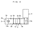
- FIG. 3 is a plane view of a base thereof
- FIG. 4 is a plane view of a main part having first pressing pieces and a second pressing piece to hold edge portions of the support mat.
- the assembly device of the support mat 13 for the ceramic catalyst carrier 14 includes a device main body 1, a base 2, a shaping die 3, an automatic tape feeder 4, a tape/support mat pressing unit 5, a tool base 6, a push-in device 7, a first pressing unit 8, a second pressing unit 9, first pressing pieces 10, a second pressing piece 11, and a push-up unit 12.
- the device main body 1 is formed to have a substantially L-shaped cross section, with a horizontal surface 1a and a vertical surface 1b.
- the base 2 is fixedly positioned on the horizontal surface 1a of the device main body 1, and its upper surface is formed as a flat surface 2a capable of holding a support mat 13 in a substantially horizontal state.
- the support mat 13 is formed in a rectangular shape, having a length long enough to be wound around an outer peripheral surface of a ceramic catalyst carrier 14 in a column shaped. Further, the support mat 13 has in both longitudinal end portions thereof, respectively, a square-shaped depression 13a and a square-shaped projection 13b engageable with the depression 13a, as shown in FIG. 3 and FIG. 4.
- the shaping die 3 is provided on an intermediate portion of the base 2 and has in an upper surface thereof a recess 3a having a shape substantially fitting a semicircular bottom surface of the ceramic catalyst carrier 14.
- the automatic tape feeder 4 is constructed to feed an adhesive tape 15 onto an upper surface of one end portion, corresponding to a right end portion in FIG. 1, of the base 2 and is fixedly positioned on the vertical surface 1b of the device main body 1. Since the automatic tape feeder 4 is a known technique, the structure thereof will not be described in detail herein. Further, the upper surface of the base 2 onto which the adhesive tape 15 is fed is coated with silicon, Teflon, or the like for adhesion prevention.
- the tape/support mat pressing unit 5 is constructed to press one end portion of the support mat 13 placed on an upper surface of the adhesive tape 15 toward the adhesive face of the adhesive tape 15 so that the adhesive tape 15 sticks to this one end portion.
- the tape/support mat pressing unit 5 is turnably disposed in one end portion, corresponding to a right end portion in FIG. 1, of the base 2.
- the tool base 6 is disposed above the shaping die 3 to be vertically movable along the vertical surface 1b of the device main body 1.
- the tool base 6 is driven in a vertical direction by a first hydraulic cylinder 6a provided in the device main body 1.
- the tool base 6 acts as a push-in unit of the present invention
- the first hydraulic cylinder 6a acts as a first actuator of the present invention.
- the push-in device 7 is provided in the tool base 6 to be vertically movable, and it has a function of pushing the ceramic catalyst carrier 14, which is placed on an upper surface of the support mat 13 placed on the upper surface of the base 2, into the recess 3a of the shaping die 3 together with the support mat 13.
- the push-in device 7 also has a function of pressing the vicinity of the engagement portions of the depression 13a and the projection 13b of the support mat 13 together with the adhesive tape 15 onto an upper surface of the ceramic catalyst carrier 14, with pressing on upper surfaces of the first pressing pieces 10 and 10 and the second pressing piece 11.
- a lower surface of the push-in device 7 has an arc shape fitting an arc-shaped upper surface of the ceramic catalyst carrier 14, and an elastic sheet 16 that is made of sponge or low-hardness silicon and has a predetermined elasticity is provided on this arc-shaped surface of the push-in device 7.
- the push-in device 7 acts as a push-in unit of the present invention, and the elastic sheet 16 corresponds to an elastic presser of the present invention.
- the push-in device 7 is driven in a direction perpendicular to the tool base 6 by a second hydraulic cylinder 7a provided in the tool base 6.
- the second hydraulic cylinder 7a acts as a second actuator of the present invention.
- the first pressing unit 8 and the second pressing unit 9 are provided on the tool base 6 so as to press the both end portions of the support mat 13 from side faces thereof so that the both end portions of the support mat 13 are curved along the arc-shaped upper surface of the ceramic catalyst carrier 14.
- the first pressing unit 8 and the second pressing unit 9 are horizontally driven toward the ceramic catalyst carrier 14 by a third hydraulic cylinder 8a and a fourth hydraulic cylinder 9a respectively.
- the third hydraulic cylinder 8a and the fourth cylinder 9a act each as an actuator of the present invention.
- the first pressing pieces 10 and the second pressing piece 11 are integrally provided in tip portions of the first pressing unit 8 and the second pressing unit 9, respectively. Specifically, the first pressing pieces 10 and 10 cover areas of the upper surface of the depression 13a side end portion of the support mat 13, excluding the depression 13a.
- the second pressing piece 11 covers an area of the upper surface of the adhesive tape 15 in the projection 13b side end portion of the support mat 13, the area corresponding to the projection 13b.
- the push-up unit 12 is provided on a bottom of the recess 3a of the shaping die 3 and it pushes up the ceramic catalyst carrier 14 together with the support mat 13.
- the push-up unit 12 is vertically driven by a fifth hydraulic cylinder 12a provided in the base 2.
- the fifth hydraulic cylinder 12a acts as an actuator of the present invention.
- the base 2 has a locking protrusion 2b for positioning the support mat 13 placed thereon. In this positioning, the locking protrusion 2b is fitted in the depression 13a of the support mat 13 to position the depression 13a side end portion of the support mat 13.
- Positioning protrusions 3b are protrudingly formed at respective four comers of an upper periphery of an opening of the recess 3a of the shaping die 3, and they are intended for width-direction positioning of an intermediate portion of the support mat 13.
- the assembly of the support mat 13 to the ceramic catalyst carrier 14 follows the procedure below.
- the existence of the elastic sheet 16 prevents the pushed upper surface of the ceramic catalyst carrier 14 from being scratched.
- the above constructed assembly device of the support mat 13 for the ceramic catalyst carrier 14 can provide the following effects. Work efficiency can be improved as a result of automating many assembly processes, and positioning accuracy in assembling the support mat 13 to the ceramic catalyst carrier 14 can be enhanced, thereby preventing poor conditions that may possibly occur when the assembled body is press-fitted into a container constituting part of an exhaust passage of an exhaust system of an engine.
- the automatic tape feeder 4 that feeds the adhesive tape 15 onto the upper surface of one of the end portions of the base 2, it is possible to set the adhesive tape 15 at a predetermined position of the base 2 without causing any undesirable variation.
- the first pressing unit 8 and the second pressing unit 9 the first pressing unit 8 to press the end portion (depression 13a side end portion) of the support mat 13 where the adhesive tape 15 is not pasted is first driven, so that the adhesive tape 15 can be surely pasted on the upper surfaces of the engagement portions.
- the tape/support mat pressing unit 5 presses the end portion (projection 13b side end portion) of the support mat 13, which is placed on the upper surface of the adhesive tape 15, toward the adhesive tape 15 so that the adhesive tape 15 sticks to the end portion.
- This structure makes it possible to surely paste the adhesive tape 15 on the end portion of the support mat 13.
- the first hydraulic cylinder 6a needs to work to concurrently carry out the two processes: namely, the process of moving down the tool base 6 to bring the push-in device 7 into contact with the upper surface of the ceramic catalyst carrier 14 placed on the upper surface of the support mat 13 while the push-up unit 12 is moved up to support the bottom of the support mat 13; and the process of moving down the first pressing unit 8 and the second pressing unit 9 to the position of the both side faces of the ceramic catalyst carrier 14 when they are to be driven. Therefore, the number of parts can be decreased and work efficiency can be improved.
- the assembly device has the two first pressing pieces 10 and 10 and the single second pressing piece 11, which are integrally formed in the tip portions of the first pressing unit 8 and the second pressing unit 9 respectively, and has the elastic sheet 16 provided on the pushing surface of the push-in device 7.
- the first pressing pieces 10 and 10 cover the areas of the upper surface excluding the depression 13a in the depression side end portion of the support mat 13
- the second pressing piece 11 covers the area of the upper surface corresponding to the projection 13b in the projection side end portion of the support mat 13
- the elastic sheet 16 has certain thickness and elasticity and when it presses the upper surfaces of the first pressing pieces 10 and 10 and the second pressing piece 11, the adhesive tape 15 can be pressed onto the upper surfaces of the engagement potions of the depression 13a and the projection 13b of the support mat 13.
- the adhesive tape 15 can be pressed from the upper surface of the first pressing pieces 10 and 10 and the second pressing piece 11. This makes it possible to press the entire vicinity of the engagement portions of the depression 13a and the projection 13b together with the adhesive tape 15 while the end portions of the support mat 13 are surely fitted along the arc-shaped upper surface of the ceramic catalyst carrier 14, so that misalignment and wrinkle of the adhesive tape 15 can be prevented.
- the assembly device of the second embodiment has the same structure as that of the first embodiment except that the position of the automatic tape feeder 4 is changed.
- the assembly device of the second embodiment is different from that of the first embodiment in that the adhesive tape 15 is fed from an end side of the base 2, as shown in the plane view in FIG. 5.
- the hydraulic cylinders are used as the first to fifth actuators, but air cylinders, electric motors, or the like can be used instead of them.
- a bottom portion of the depression 13a may be larger than an opening portion of thereof in width and a tip portion of the projection 13b may be larger than a base portion thereof in width.
Landscapes
- Engineering & Computer Science (AREA)
- Chemical & Material Sciences (AREA)
- Chemical Kinetics & Catalysis (AREA)
- Mechanical Engineering (AREA)
- Combustion & Propulsion (AREA)
- General Engineering & Computer Science (AREA)
- Health & Medical Sciences (AREA)
- Toxicology (AREA)
- Catalysts (AREA)
- Exhaust Gas After Treatment (AREA)
Abstract
Description
Claims (7)
- An assembly device of a support mat for a ceramic catalyst carrier, comprising:a base (2) capable of holding a support mat (13) in a flat plate shape substantially horizontally;a shaping die (3) provided on a substantially center portion of the base (2) and having a recess (3 a) that has a shape substantially fitting a semicircular bottom surface of the ceramic catalyst carrier (14);a push-in unit capable of pushing the ceramic catalyst carrier (14) together with the support mat (13) into the recess (3a) of the shaping die (3);a first pressing unit (8) and a second pressing unit (9) that press both end portions of the support mat (13) from side faces so as to curve the both end portions of the support mat (13) along an arc-shaped upper surface of the ceramic catalyst carrier (14); anda push-up unit (12) provided on a bottom of the recess (3a) in the shaping die (3) and capable of pushing up the ceramic catalyst carrier (14) together with the support mat (13).
- The assembly device of the support mat for the ceramic catalyst carrier according to claim 1, wherein
the support mat (13) has in the both end portions thereof, respectively, a depression (13a) and a projection (13b) engageable with the depression (13a). - The assembly device of the support mat for the ceramic catalyst carrier according to claim 1 or claim 2, further comprising
an automatic tape feeder (4) feeding an adhesive tape (15) to an upper surface of one end portion of the base (2). - The assembly device of the support mat for the ceramic catalyst carrier according to claim 3, wherein
one of the first pressing unit (8) and the second pressing unit (9) that is to press one of the end portions of the support mat (13) where the adhesive tape (15) is not pasted is driven before the other one of the first and second pressing units (8, 9) is driven. - The assembly device of the support mat for the ceramic catalyst carrier according to claim 3 or claim 4, further comprising
a tape/support mat pressing unit (5) that presses the other end portion of the support mat (13) toward the adhesive tape (15) while the other end portion of the support mat (13) is placed on an upper surface of the adhesive tape (15), thereby sticking the adhesive tape (15) to the other end portion. - The assembly device of the support mat for the ceramic catalyst carrier according to any one of to claim 1 to claim 5, wherein:the push-in unit is composed of: a tool base (6) provided above the shaping die (3) and driven by a first actuator (6a) to be vertically movable; and a push-in device (7) provided in the tool base (6) and driven by a second actuator (7a) to be capable of pushing the ceramic catalyst carrier (14) together with the support mat (13) into the recess (3 a) of the shaping die (3); andthe first pressing unit (8) and the second pressing unit (9) are provided on the tool base (6).
- The assembly device of the support mat for the ceramic catalyst carrier according to claim 6, further comprising:a plurality of first pressing pieces (10) and at least one second pressing piece (11) that are integrally provided in tip portions of the first pressing unit (8) and the second pressing unit (9) respectively: the first pressing pieces (10) covering areas of an upper surface excluding the depression (13a) in the depression-side end portion of the support mat (13); and the second pressing piece (11) covering an area of the upper surface corresponding to the projection (13b) in the projection-side end portion of the support mat (13); andan elastic presser (16) provided on a pressing surface of the push-in unit, having a thickness and elasticity, and capable of pressing the adhesive tape (15) onto an upper surfaces of engagement portions of the depression (13a) and the projection (13b) of the support mat (13) by pressing upper surfaces of the first pressing pieces (10) and the second pressing piece (11).
Applications Claiming Priority (2)
| Application Number | Priority Date | Filing Date | Title |
|---|---|---|---|
| JP2003433761 | 2003-12-26 | ||
| JP2003433761A JP2005186017A (en) | 2003-12-26 | 2003-12-26 | Apparatus for integrating holding mat with ceramic catalyst carrier |
Publications (2)
| Publication Number | Publication Date |
|---|---|
| EP1548244A1 true EP1548244A1 (en) | 2005-06-29 |
| EP1548244B1 EP1548244B1 (en) | 2006-08-30 |
Family
ID=34545085
Family Applications (1)
| Application Number | Title | Priority Date | Filing Date |
|---|---|---|---|
| EP04293134A Expired - Lifetime EP1548244B1 (en) | 2003-12-26 | 2004-12-24 | Assembly device of support mat and for ceramic catalyst carrier |
Country Status (4)
| Country | Link |
|---|---|
| US (1) | US7441333B2 (en) |
| EP (1) | EP1548244B1 (en) |
| JP (1) | JP2005186017A (en) |
| DE (1) | DE602004002184T2 (en) |
Cited By (1)
| Publication number | Priority date | Publication date | Assignee | Title |
|---|---|---|---|---|
| CN106216511A (en) * | 2016-07-26 | 2016-12-14 | 滁州达世汽车配件有限公司 | Automobile flanging and restriking mould with material pressing core |
Families Citing this family (3)
| Publication number | Priority date | Publication date | Assignee | Title |
|---|---|---|---|---|
| JP4647409B2 (en) * | 2005-06-22 | 2011-03-09 | 株式会社ヒロテック | Manufacturing method of catalytic converter and manufacturing apparatus used in the manufacturing method |
| BRPI0812787B1 (en) * | 2007-06-01 | 2019-10-29 | Yutaka Giken Co Ltd | method for compressing a mat of an exhaust gas cleaner having a catalyst and apparatus for compressing a mat against a cylindrical catalyst |
| DE102007034832B4 (en) | 2007-07-26 | 2018-11-15 | Volkswagen Ag | Winding element for a ceramic honeycomb body of a catalyst |
Citations (4)
| Publication number | Priority date | Publication date | Assignee | Title |
|---|---|---|---|---|
| JPH07269334A (en) * | 1994-03-31 | 1995-10-17 | Ibiden Co Ltd | How to install the converter heat insulating sealant for automobile exhaust gas purification |
| JPH09264126A (en) * | 1996-03-29 | 1997-10-07 | Ibiden Co Ltd | Method for manufacturing catalytic converter for purifying exhaust gas |
| JPH10131744A (en) * | 1996-10-28 | 1998-05-19 | Yamaha Motor Co Ltd | Method for supporting ceramic catalyst carrier and exhaust device with ceramic catalyst carrier |
| EP1344911A1 (en) * | 2002-03-05 | 2003-09-17 | Sango Co., Ltd. | Method and apparatus of producing a columnar member container |
Family Cites Families (8)
| Publication number | Priority date | Publication date | Assignee | Title |
|---|---|---|---|---|
| US1200190A (en) * | 1913-10-15 | 1916-10-03 | Paul R Hahnemann | Can-body-forming machine. |
| JPS5817335B2 (en) * | 1975-04-10 | 1983-04-06 | トヨタ自動車株式会社 | Method for manufacturing integrated catalyst component for exhaust gas purification |
| CA1119469A (en) * | 1979-10-09 | 1982-03-09 | George R. Usher | Apparatus and method for forming seamed tube |
| JP4652553B2 (en) * | 2000-11-10 | 2011-03-16 | イビデン株式会社 | Catalytic converter and manufacturing method thereof |
| US7252731B2 (en) * | 2000-11-20 | 2007-08-07 | 3M Innovative Properties Company | Apparatus and method for applying double-coated pressure sensitive adhesive tape, and method for producing catalytic converter |
| DE10242283B4 (en) * | 2002-09-12 | 2005-09-08 | J. Eberspächer GmbH & Co. KG | Apparatus and method for pressing a bearing mat to a monolith |
| JP2005194917A (en) * | 2004-01-05 | 2005-07-21 | Calsonic Kansei Corp | Mat installation device for holding ceramic catalyst carrier |
| US20060016063A1 (en) * | 2004-07-26 | 2006-01-26 | Gharib Mohamed T | Lockseaming process and apparatus for the same |
-
2003
- 2003-12-26 JP JP2003433761A patent/JP2005186017A/en active Pending
-
2004
- 2004-12-23 US US11/019,198 patent/US7441333B2/en not_active Expired - Fee Related
- 2004-12-24 DE DE602004002184T patent/DE602004002184T2/en not_active Expired - Fee Related
- 2004-12-24 EP EP04293134A patent/EP1548244B1/en not_active Expired - Lifetime
Patent Citations (4)
| Publication number | Priority date | Publication date | Assignee | Title |
|---|---|---|---|---|
| JPH07269334A (en) * | 1994-03-31 | 1995-10-17 | Ibiden Co Ltd | How to install the converter heat insulating sealant for automobile exhaust gas purification |
| JPH09264126A (en) * | 1996-03-29 | 1997-10-07 | Ibiden Co Ltd | Method for manufacturing catalytic converter for purifying exhaust gas |
| JPH10131744A (en) * | 1996-10-28 | 1998-05-19 | Yamaha Motor Co Ltd | Method for supporting ceramic catalyst carrier and exhaust device with ceramic catalyst carrier |
| EP1344911A1 (en) * | 2002-03-05 | 2003-09-17 | Sango Co., Ltd. | Method and apparatus of producing a columnar member container |
Non-Patent Citations (3)
| Title |
|---|
| PATENT ABSTRACTS OF JAPAN vol. 1996, no. 02 29 February 1996 (1996-02-29) * |
| PATENT ABSTRACTS OF JAPAN vol. 1998, no. 02 30 January 1998 (1998-01-30) * |
| PATENT ABSTRACTS OF JAPAN vol. 1998, no. 10 31 August 1998 (1998-08-31) * |
Cited By (2)
| Publication number | Priority date | Publication date | Assignee | Title |
|---|---|---|---|---|
| CN106216511A (en) * | 2016-07-26 | 2016-12-14 | 滁州达世汽车配件有限公司 | Automobile flanging and restriking mould with material pressing core |
| CN106216511B (en) * | 2016-07-26 | 2018-01-02 | 滁州达世汽车配件有限公司 | Automobile flanging and restriking mould with material pressing core |
Also Published As
| Publication number | Publication date |
|---|---|
| DE602004002184T2 (en) | 2007-07-19 |
| US20050142044A1 (en) | 2005-06-30 |
| US7441333B2 (en) | 2008-10-28 |
| EP1548244B1 (en) | 2006-08-30 |
| JP2005186017A (en) | 2005-07-14 |
| DE602004002184D1 (en) | 2006-10-12 |
Similar Documents
| Publication | Publication Date | Title |
|---|---|---|
| US7753351B2 (en) | Clamp device | |
| EP1548244B1 (en) | Assembly device of support mat and for ceramic catalyst carrier | |
| EP1550798B1 (en) | Assembly device of support mat for ceramic catalyst carrier | |
| EP1136148A3 (en) | Composite panel and method of bending the same | |
| FR3058284A1 (en) | PACKAGE OF SHEETS FIXED BETWEEN THEM BY ADHESION, METHOD AND INSTALLATION FOR MANUFACTURING SUCH A PACKAGE OF SHEETS | |
| EP0995511A3 (en) | Layered material and method for manufacturing same | |
| EP1738860B1 (en) | Clamp device | |
| US20070180695A1 (en) | Method and device for press-fitting, into storage outer tube, ceramic catalyst carrier having non-expansion mat wrapped therearound into storage outer tube | |
| JP2004202510A (en) | Hemming equipment | |
| JP3287958B2 (en) | Method and apparatus for assembling elastic ring member | |
| JPH0422908Y2 (en) | ||
| JP2534366B2 (en) | Automotive roof molding method | |
| JPH0517292U (en) | Plug-in welding flange | |
| JP2628501B2 (en) | Manufacturing method of unit tile | |
| JPH0423001Y2 (en) | ||
| JPH08246006A (en) | Sintering method of green compact | |
| JP2005014017A (en) | Welding jig system | |
| JP2000002214A (en) | Corner material forming jig | |
| JPH11185651A (en) | Aperture grill, assembling method and assembling apparatus | |
| JPH10233429A (en) | Adhesive tape sticking device to substrate | |
| JP2002101535A (en) | Attaching method of wire harness | |
| JP2001044311A (en) | Edge bonding structure of CAP for device | |
| JPH10104796A (en) | Method and apparatus for loading sheet-shaped photosensitive material | |
| JPH07237414A (en) | Bush boss fixing structure | |
| JPH04131517U (en) | automotive door trim |
Legal Events
| Date | Code | Title | Description |
|---|---|---|---|
| PUAI | Public reference made under article 153(3) epc to a published international application that has entered the european phase |
Free format text: ORIGINAL CODE: 0009012 |
|
| AK | Designated contracting states |
Kind code of ref document: A1 Designated state(s): AT BE BG CH CY CZ DE DK EE ES FI FR GB GR HU IE IS IT LI LT LU MC NL PL PT RO SE SI SK TR |
|
| AX | Request for extension of the european patent |
Extension state: AL BA HR LV MK YU |
|
| 17P | Request for examination filed |
Effective date: 20051006 |
|
| GRAP | Despatch of communication of intention to grant a patent |
Free format text: ORIGINAL CODE: EPIDOSNIGR1 |
|
| AKX | Designation fees paid |
Designated state(s): DE FR GB |
|
| GRAS | Grant fee paid |
Free format text: ORIGINAL CODE: EPIDOSNIGR3 |
|
| GRAA | (expected) grant |
Free format text: ORIGINAL CODE: 0009210 |
|
| AK | Designated contracting states |
Kind code of ref document: B1 Designated state(s): DE FR GB |
|
| REG | Reference to a national code |
Ref country code: GB Ref legal event code: FG4D |
|
| REF | Corresponds to: |
Ref document number: 602004002184 Country of ref document: DE Date of ref document: 20061012 Kind code of ref document: P |
|
| ET | Fr: translation filed | ||
| PLBE | No opposition filed within time limit |
Free format text: ORIGINAL CODE: 0009261 |
|
| STAA | Information on the status of an ep patent application or granted ep patent |
Free format text: STATUS: NO OPPOSITION FILED WITHIN TIME LIMIT |
|
| 26N | No opposition filed |
Effective date: 20070531 |
|
| PGFP | Annual fee paid to national office [announced via postgrant information from national office to epo] |
Ref country code: FR Payment date: 20081212 Year of fee payment: 5 |
|
| PGFP | Annual fee paid to national office [announced via postgrant information from national office to epo] |
Ref country code: DE Payment date: 20081219 Year of fee payment: 5 |
|
| PGFP | Annual fee paid to national office [announced via postgrant information from national office to epo] |
Ref country code: GB Payment date: 20081224 Year of fee payment: 5 |
|
| GBPC | Gb: european patent ceased through non-payment of renewal fee |
Effective date: 20091224 |
|
| REG | Reference to a national code |
Ref country code: FR Ref legal event code: ST Effective date: 20100831 |
|
| PG25 | Lapsed in a contracting state [announced via postgrant information from national office to epo] |
Ref country code: FR Free format text: LAPSE BECAUSE OF NON-PAYMENT OF DUE FEES Effective date: 20091231 |
|
| PG25 | Lapsed in a contracting state [announced via postgrant information from national office to epo] |
Ref country code: DE Free format text: LAPSE BECAUSE OF NON-PAYMENT OF DUE FEES Effective date: 20100701 |
|
| PG25 | Lapsed in a contracting state [announced via postgrant information from national office to epo] |
Ref country code: GB Free format text: LAPSE BECAUSE OF NON-PAYMENT OF DUE FEES Effective date: 20091224 |