EP1547852A2 - Power supply assembly for electric vehicle - Google Patents
Power supply assembly for electric vehicle Download PDFInfo
- Publication number
- EP1547852A2 EP1547852A2 EP04256252A EP04256252A EP1547852A2 EP 1547852 A2 EP1547852 A2 EP 1547852A2 EP 04256252 A EP04256252 A EP 04256252A EP 04256252 A EP04256252 A EP 04256252A EP 1547852 A2 EP1547852 A2 EP 1547852A2
- Authority
- EP
- European Patent Office
- Prior art keywords
- power supply
- main structural
- personalized
- housing
- supply unit
- Prior art date
- Legal status (The legal status is an assumption and is not a legal conclusion. Google has not performed a legal analysis and makes no representation as to the accuracy of the status listed.)
- Withdrawn
Links
Images


Classifications
-
- B—PERFORMING OPERATIONS; TRANSPORTING
- B62—LAND VEHICLES FOR TRAVELLING OTHERWISE THAN ON RAILS
- B62K—CYCLES; CYCLE FRAMES; CYCLE STEERING DEVICES; RIDER-OPERATED TERMINAL CONTROLS SPECIALLY ADAPTED FOR CYCLES; CYCLE AXLE SUSPENSIONS; CYCLE SIDECARS, FORECARS, OR THE LIKE
- B62K5/00—Cycles with handlebars, equipped with three or more main road wheels
- B62K5/02—Tricycles
- B62K5/023—Tricycles specially adapted for disabled riders, e.g. personal mobility type vehicles with three wheels
- B62K5/025—Tricycles specially adapted for disabled riders, e.g. personal mobility type vehicles with three wheels power-driven
-
- B—PERFORMING OPERATIONS; TRANSPORTING
- B60—VEHICLES IN GENERAL
- B60L—PROPULSION OF ELECTRICALLY-PROPELLED VEHICLES; SUPPLYING ELECTRIC POWER FOR AUXILIARY EQUIPMENT OF ELECTRICALLY-PROPELLED VEHICLES; ELECTRODYNAMIC BRAKE SYSTEMS FOR VEHICLES IN GENERAL; MAGNETIC SUSPENSION OR LEVITATION FOR VEHICLES; MONITORING OPERATING VARIABLES OF ELECTRICALLY-PROPELLED VEHICLES; ELECTRIC SAFETY DEVICES FOR ELECTRICALLY-PROPELLED VEHICLES
- B60L50/00—Electric propulsion with power supplied within the vehicle
- B60L50/50—Electric propulsion with power supplied within the vehicle using propulsion power supplied by batteries or fuel cells
- B60L50/60—Electric propulsion with power supplied within the vehicle using propulsion power supplied by batteries or fuel cells using power supplied by batteries
- B60L50/64—Constructional details of batteries specially adapted for electric vehicles
-
- B—PERFORMING OPERATIONS; TRANSPORTING
- B60—VEHICLES IN GENERAL
- B60L—PROPULSION OF ELECTRICALLY-PROPELLED VEHICLES; SUPPLYING ELECTRIC POWER FOR AUXILIARY EQUIPMENT OF ELECTRICALLY-PROPELLED VEHICLES; ELECTRODYNAMIC BRAKE SYSTEMS FOR VEHICLES IN GENERAL; MAGNETIC SUSPENSION OR LEVITATION FOR VEHICLES; MONITORING OPERATING VARIABLES OF ELECTRICALLY-PROPELLED VEHICLES; ELECTRIC SAFETY DEVICES FOR ELECTRICALLY-PROPELLED VEHICLES
- B60L50/00—Electric propulsion with power supplied within the vehicle
- B60L50/50—Electric propulsion with power supplied within the vehicle using propulsion power supplied by batteries or fuel cells
- B60L50/60—Electric propulsion with power supplied within the vehicle using propulsion power supplied by batteries or fuel cells using power supplied by batteries
- B60L50/66—Arrangements of batteries
-
- B—PERFORMING OPERATIONS; TRANSPORTING
- B60—VEHICLES IN GENERAL
- B60L—PROPULSION OF ELECTRICALLY-PROPELLED VEHICLES; SUPPLYING ELECTRIC POWER FOR AUXILIARY EQUIPMENT OF ELECTRICALLY-PROPELLED VEHICLES; ELECTRODYNAMIC BRAKE SYSTEMS FOR VEHICLES IN GENERAL; MAGNETIC SUSPENSION OR LEVITATION FOR VEHICLES; MONITORING OPERATING VARIABLES OF ELECTRICALLY-PROPELLED VEHICLES; ELECTRIC SAFETY DEVICES FOR ELECTRICALLY-PROPELLED VEHICLES
- B60L53/00—Methods of charging batteries, specially adapted for electric vehicles; Charging stations or on-board charging equipment therefor; Exchange of energy storage elements in electric vehicles
- B60L53/80—Exchanging energy storage elements, e.g. removable batteries
-
- B—PERFORMING OPERATIONS; TRANSPORTING
- B60—VEHICLES IN GENERAL
- B60L—PROPULSION OF ELECTRICALLY-PROPELLED VEHICLES; SUPPLYING ELECTRIC POWER FOR AUXILIARY EQUIPMENT OF ELECTRICALLY-PROPELLED VEHICLES; ELECTRODYNAMIC BRAKE SYSTEMS FOR VEHICLES IN GENERAL; MAGNETIC SUSPENSION OR LEVITATION FOR VEHICLES; MONITORING OPERATING VARIABLES OF ELECTRICALLY-PROPELLED VEHICLES; ELECTRIC SAFETY DEVICES FOR ELECTRICALLY-PROPELLED VEHICLES
- B60L2200/00—Type of vehicles
- B60L2200/24—Personal mobility vehicles
-
- Y—GENERAL TAGGING OF NEW TECHNOLOGICAL DEVELOPMENTS; GENERAL TAGGING OF CROSS-SECTIONAL TECHNOLOGIES SPANNING OVER SEVERAL SECTIONS OF THE IPC; TECHNICAL SUBJECTS COVERED BY FORMER USPC CROSS-REFERENCE ART COLLECTIONS [XRACs] AND DIGESTS
- Y02—TECHNOLOGIES OR APPLICATIONS FOR MITIGATION OR ADAPTATION AGAINST CLIMATE CHANGE
- Y02E—REDUCTION OF GREENHOUSE GAS [GHG] EMISSIONS, RELATED TO ENERGY GENERATION, TRANSMISSION OR DISTRIBUTION
- Y02E60/00—Enabling technologies; Technologies with a potential or indirect contribution to GHG emissions mitigation
- Y02E60/10—Energy storage using batteries
-
- Y—GENERAL TAGGING OF NEW TECHNOLOGICAL DEVELOPMENTS; GENERAL TAGGING OF CROSS-SECTIONAL TECHNOLOGIES SPANNING OVER SEVERAL SECTIONS OF THE IPC; TECHNICAL SUBJECTS COVERED BY FORMER USPC CROSS-REFERENCE ART COLLECTIONS [XRACs] AND DIGESTS
- Y02—TECHNOLOGIES OR APPLICATIONS FOR MITIGATION OR ADAPTATION AGAINST CLIMATE CHANGE
- Y02T—CLIMATE CHANGE MITIGATION TECHNOLOGIES RELATED TO TRANSPORTATION
- Y02T10/00—Road transport of goods or passengers
- Y02T10/60—Other road transportation technologies with climate change mitigation effect
- Y02T10/70—Energy storage systems for electromobility, e.g. batteries
-
- Y—GENERAL TAGGING OF NEW TECHNOLOGICAL DEVELOPMENTS; GENERAL TAGGING OF CROSS-SECTIONAL TECHNOLOGIES SPANNING OVER SEVERAL SECTIONS OF THE IPC; TECHNICAL SUBJECTS COVERED BY FORMER USPC CROSS-REFERENCE ART COLLECTIONS [XRACs] AND DIGESTS
- Y02—TECHNOLOGIES OR APPLICATIONS FOR MITIGATION OR ADAPTATION AGAINST CLIMATE CHANGE
- Y02T—CLIMATE CHANGE MITIGATION TECHNOLOGIES RELATED TO TRANSPORTATION
- Y02T10/00—Road transport of goods or passengers
- Y02T10/60—Other road transportation technologies with climate change mitigation effect
- Y02T10/7072—Electromobility specific charging systems or methods for batteries, ultracapacitors, supercapacitors or double-layer capacitors
-
- Y—GENERAL TAGGING OF NEW TECHNOLOGICAL DEVELOPMENTS; GENERAL TAGGING OF CROSS-SECTIONAL TECHNOLOGIES SPANNING OVER SEVERAL SECTIONS OF THE IPC; TECHNICAL SUBJECTS COVERED BY FORMER USPC CROSS-REFERENCE ART COLLECTIONS [XRACs] AND DIGESTS
- Y02—TECHNOLOGIES OR APPLICATIONS FOR MITIGATION OR ADAPTATION AGAINST CLIMATE CHANGE
- Y02T—CLIMATE CHANGE MITIGATION TECHNOLOGIES RELATED TO TRANSPORTATION
- Y02T90/00—Enabling technologies or technologies with a potential or indirect contribution to GHG emissions mitigation
- Y02T90/10—Technologies relating to charging of electric vehicles
- Y02T90/12—Electric charging stations
-
- Y—GENERAL TAGGING OF NEW TECHNOLOGICAL DEVELOPMENTS; GENERAL TAGGING OF CROSS-SECTIONAL TECHNOLOGIES SPANNING OVER SEVERAL SECTIONS OF THE IPC; TECHNICAL SUBJECTS COVERED BY FORMER USPC CROSS-REFERENCE ART COLLECTIONS [XRACs] AND DIGESTS
- Y02—TECHNOLOGIES OR APPLICATIONS FOR MITIGATION OR ADAPTATION AGAINST CLIMATE CHANGE
- Y02T—CLIMATE CHANGE MITIGATION TECHNOLOGIES RELATED TO TRANSPORTATION
- Y02T90/00—Enabling technologies or technologies with a potential or indirect contribution to GHG emissions mitigation
- Y02T90/10—Technologies relating to charging of electric vehicles
- Y02T90/14—Plug-in electric vehicles
-
- Y—GENERAL TAGGING OF NEW TECHNOLOGICAL DEVELOPMENTS; GENERAL TAGGING OF CROSS-SECTIONAL TECHNOLOGIES SPANNING OVER SEVERAL SECTIONS OF THE IPC; TECHNICAL SUBJECTS COVERED BY FORMER USPC CROSS-REFERENCE ART COLLECTIONS [XRACs] AND DIGESTS
- Y10—TECHNICAL SUBJECTS COVERED BY FORMER USPC
- Y10S—TECHNICAL SUBJECTS COVERED BY FORMER USPC CROSS-REFERENCE ART COLLECTIONS [XRACs] AND DIGESTS
- Y10S180/00—Motor vehicles
- Y10S180/907—Motorized wheelchairs
-
- Y—GENERAL TAGGING OF NEW TECHNOLOGICAL DEVELOPMENTS; GENERAL TAGGING OF CROSS-SECTIONAL TECHNOLOGIES SPANNING OVER SEVERAL SECTIONS OF THE IPC; TECHNICAL SUBJECTS COVERED BY FORMER USPC CROSS-REFERENCE ART COLLECTIONS [XRACs] AND DIGESTS
- Y10—TECHNICAL SUBJECTS COVERED BY FORMER USPC
- Y10S—TECHNICAL SUBJECTS COVERED BY FORMER USPC CROSS-REFERENCE ART COLLECTIONS [XRACs] AND DIGESTS
- Y10S180/00—Motor vehicles
- Y10S180/908—Motor vehicles with short wheelbase
Definitions
- the present invention relates to Power Supply Assemblies (PSAs) for Personalized Motorized Vehicles, and more particularly, to a new and useful detachable mounting assembly therefor which facilitates ease of attachment of a Power Supply Unit (PSU) to a main structural frame of the PMV, provides a positive electrical and structural connection therebetween, and integrates the power supply assembly with the external geometry of the PMV to provide an aesthetically pleasing external appearance.
- PSAs Power Supply Assemblies
- PSU Power Supply Unit
- PMVs Personalized Motorized Vehicles
- ADA Americans with Disabilities Act
- the ADA has, inter alia, effected sweeping changes to provide equal access and freedom of movement/mobility for disabled individuals.
- various structural changes have been mandated to the construction of homes, sidewalks, and even parkway/river crossings, e.g., bridges, to enlarge entrances and provide ramped surfaces to ease mobility for disabled persons in and around society.
- PMVs offer an environmentally friendly alternative to gasoline burning vehicles such as gas-powered scooters, mopeds, motorcycles, etc.
- various technologies have made the mass production of such PMVs fiscally rewarding to manufacturers and affordable for the consumer.
- long-life rechargeable power supply units e.g., lithium batteries, fuel cells, etc.
- each battery is mounted to a floor pan of the PMV by means of a pair of long threaded rods disposed on opposite sides of a battery for clamping the battery to the floor pan.
- Each rod has a L-bracket at one end for engaging an upper surface of the power supply unit and a J-hook at the other end engaging a mounting aperture of the floor pan.
- each L-bracket includes an aperture for engaging and sliding longitudinally along the rod. The rod is urged against the battery by a conventional wing-nut. Consequently, to remove the battery, the wing-nuts are loosened to disengage the L-brackets and the rods are displaced sufficiently to enable the battery to clear the brackets.
- each battery will include a strap extending across its top to facilitate handling of the battery. While this assembly provides a positive mounting arrangement for attaching the battery to the floor pan of the PMV (such positive mounting being especially critical for batteries subject to motion or vibration), this mounting arrangement does not facilitate rapid removal and reassembly.
- a typical hook & rail assembly may include, for example, J-shaped hooks disposed in combination with a battery/battery box for being hung on a pair of parallel rails attached to and supported by the PMV frame.
- the battery/battery box may be installed vertically and relies upon its own weight to prevent the hooks from disengaging the rails. While this mounting arrangement facilitates ease of installation or disassembly, it does not positively retain the battery/battery box and, consequently, may not be suited for certain PMVs which experience vertical motion/acceleration, e.g. travelling upon rough terrain.
- channels are formed in combination with the battery/battery box and engage tracks attached to the PMV frame. Installation and disassembly of the battery/battery box requires that the channels slideably engage the track by insertion of the channels through an open end of the track. As such the battery/battery box does not "dropped in” vertically (possible with the hook & rail assembly discussed supra), but slides in horizontally. While the channels and track can be configured to positively engage and retain the battery/battery box, the mounting arrangement requires that space be provided for the battery/battery box to slide in a horizontal plane for engaging the track. Accordingly, this mounting arrangement may be unsuitable for PMVs wherein space is a design constraint.
- the battery/battery box and/or mounting assemblies therefor produce an aesthetically unattractive external appearance. Consequently, such components and assemblies are typically occluded or hidden from sight by a more aesthetically pleasing chassis element or PMV component.
- a contoured external fuselage or a seat/seat support assembly may be disposed over the battery/battery box to preclude viewing of the battery/battery box and/or mounting arrangement. Consequently, these elements or assemblies must be additionally removed to access and disassemble the battery/battery box.
- a power supply assembly is provided for a Personalized Motorized Vehicle (PMV) including a detachable mounting assembly therefor which facilitates the ease of attachment of a Power Supply Unit (PSU) to a main structural frame of the PMV, provides a positive electrical and structural connection therebetween, and integrates the power supply assembly with the external geometry of the PMV to provide an aesthetically pleasing external profile.
- the power supply assembly includes a pair of PSUs, each unit having a housing structure which includes at least one segment projecting from a center body portion thereof. A segment of one PSU unit overlaps a segment of another PSU unit and another segment of one PSU overlaps a portion of the main structural frame. Electrical connectors are disposed in combination with the overlapping housing segments for electrically coupling the PSUs and at least one PSU to the PMV.
- the power supply assembly furthermore, includes a retention subassembly for structurally connecting each PSU to the main structural frame. More specifically, the retention subassembly comprises a base support for accepting a power supply unit and having retention walls for in-plane retention of the power supply unit, an aperture disposed in the housing structure and a latching mechanism engaging the aperture for vertically retaining the power supply unit.
- the power supply units produce a geometrically blended external profile when the housing structures are juxtaposed. Furthermore, the handle of the latching mechanism is externally accessible and geometrically blends with the external contour of the main structural frame.
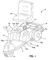
- FIG 1 is a perspective view of a Personalized Motorized Vehicle (PMV) employing a Power Supply Assembly (PSA) according to the present invention.
- PMV Personalized Motorized Vehicle
- PSA Power Supply Assembly
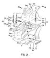
- FIG. 2 is an exploded view of the relevant components of the PSA including electrical connectors, a retaining subassembly, and a pair of Power Supply Units (PSU).
- PSU Power Supply Unit
- Figure 3a is an enlarged view isolated view of the male and female contacts of an electrical connector employed in the PSA of the present invention.
- Figure 3b is a cross sectional view all of an assembled connector employed in the PSA of the present invention.
- Figure 4 is a cross the sectional view of taken substantially along line 4-4 of Figure 1.
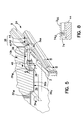
- Figure 5 is a partially broken away cross sectional view of the retention assembly according to the present invention.
- Figure 6 is a cross sectional view taken substantially along line 6-6 of Figure 5 depicting a pin engaging an aperture of a Power Supply Unit (PSU).
- PSU Power Supply Unit
- Figure 7 is a cross sectional view taken substantially along line 7-7 of Figure 5.
- Figure 8 is a cross sectional view taken substantially along line 8-8 of Figure 5.
- Fig. 1 depicts a Personalized Motorized Vehicle (PMV) 2 including a Power Supply Assembly (PSA) 20 according to the present invention.
- the PMV 2 is a three-wheeled scooter having a main structural frame 3, a seat 4a, a seat support stanchion 4b (raised relative to the main body), a front wheel 5 disposed in combination with a steering column 6, a pair of aft wheels 7 (only one being shown in the perspective view), a contoured chassis 9, and a pair of Power Supply Units (PSU) 10a, 10b, e.g., batteries.
- PSU Power Supply Units
- the main structural frame 3 includes a forward frame portion for mounting the steering column 6, an aft frame portion for mounting the aft wheels 7, side supports 3 SS for structurally interconnecting the forward and aft frame portions, and at least one cross member 3 CM for structurally interconnecting the side frame supports 3 SS .
- a drive train assembly (not shown) is disposed aft of the seat 4a and includes a high torque electric motor for driving the aft wheels 6 through a reduction gearbox.
- the PMV 2 is operated by conventional throttle controls 16 disposed on the steering column 8 for issuing commands to a controller (not shown) through a power distribution system (e.g., wiring harnesses) for providing electric power to the PMV 2.
- the PSA 20 comprises elements which effect electrical continuity between one of the PSU 10a, 10b and electrical systems/harnesses of the PMV 2, continuity between one of the PSU 10a, 10b and a charging unit, or continuity between two or more PSUs 10a, 10b.
- the PSA 20 comprises the elements which are interposed between the frame 3 and at least one of the power supply units 10a, 10b and functions to secure the power supply units 10a, 10b to the main structural frame 3.
- the PSA 20 comprises elements which integrate one of the PSUs 10a, 10b within or to the contoured chassis 9.
- the main structural frame 3 is defined to include any structural element rigidly affixed or stationary with respect to the frame 3.
- portions of the contoured chassis 9 may be viewed as sub-elements of the main structural frame 3.
- a PSU is defined to include elements which are integral with the PSU or, elements which, for all intents and purposes, are permanently affixed to a PSU and only removed or disconnected for repair and/or maintenance.
- a battery box or container which houses a battery and contains the necessary electrical connections therebetween, is also part of the PSU 10.
- the Power Supply Assembly 20 comprises (i) the Power Supply Units 10a, 10b, (ii) electrical connectors 22 for establishing electrical connections between: (i)(a) PSU 10a and PSU 10b, and (i)(b) one of the PSUs 10a, 10b and the PMV 2, and (ii) a retention subassembly 24 for positively engaging the PSUs 10a, 10b relative to the frame 3.
- the PSA 20 i.e., the electrical connector 22 and retention subassembly 24, will be discussed in greater detail in the subsequent paragraphs.
- each of the PSUs 10a, 10b includes a housing structure 30a, 30b, portions of which project from the center body portion, to support and facilitate alignment of the electrical connectors 22. More specifically, each of the PSU 10a, 10b includes laterally projecting/recessing housing segments 30 LA , one such segment 30 LAa geometrically interlocking with the other segment 30 Lb , to effect an electrical connection between the PSUs 10a, 10b.
- the segments 30 LAa , 30 LAb are juxtaposed in relation to the segments 30 LAa , 30 LAb , of the opposed housing structure 30a, 30b.
- the segments 30 LAa 30 LAb overlap such that relative vertical displacement of the PSUs 10a, 10b will effect electrical engagement of the contacts 22 L1 , 22 L2 . That is, the male contacts 22 M of the electrical connectors 22 L1 , 22 L2 are disposed in combination with the upper overlapping segment 30 LAa while female contacts 22 F are disposed in combination with the lower overlapping segment 30 LAb .
- the term "overlapping" means that the segments 30 La , 30 Lb and their respective connectors 22 M , 22 F define a substantially horizontal mating plane.
- each male contact 22 M includes a vertically oriented cylindrical post 22 MP (best seen in Fig. 3a) and each female contact 22 F includes an cylindrical array of longitudinal fingers 22 FLF .
- the cylindrical array of fingers 22 FLF spread to accept the post 22 MP (i.e., the long slender shape of fingers effects a series of cantilever springs which spread and capture the post 22 MP ).
- the PSU housing structures 30a, 30b include longitudinally projecting segments 30 LOa , 30 LOb for supporting and mounting the primary electrical connectors 22 P(+) , 22 N(-) , 22 G(0) for powering the PMV 2.
- the longitudinal segments 30 LOa , 30 LOb may also be viewed as overlapping with respect to the underlying main structural frame 3.
- the positive and negative contacts 22 P(+) , 22 N(-) are mounted in combination with one of the PSUs 10a while the ground contact 22 G(0) is mounted in combination with the other of the PSUs 10b.
- at least one of the PSUs 10a may include an electrical port 31 for recharging the PSUs 10a, 10b.
- the PSUs 10a, 10b are electrically coupled, i.e., coupled via lateral contacts 22 L1 , 22 L2 .
- PSUs 10a, 10b can be recharged while not attached to the PMV 2.
- PSUs 10a, 10b can be removed from the PMV 2, recoupled together, and recharged simultaneously as a unit via electrical port 31 while not attached to the PMV 2 using an external power source (e.g., battery charger coupled to a household electrical outlet).
- an external power source e.g., battery charger coupled to a household electrical outlet.
- housing structures 30a, 30b mate to form a geometrically blended external profile.
- geometrically blended means that portions of the housing structures are contiguous and are substantially flush (i.e., no abrupt changes in the external geometry, e.g., steps) at the juncture of the housing structures 30a, 30b.
- the overlapping segments 30 LAa 30 LAb form an interlocking ellipse (best seen in Fig. 1) wherein the visible portion of the housing segments, i.e., segment 30 LAb , smoothly blends at the juncture of the housing structures 30a, 30b.
- overlapping segments 30 LOa , 30 LOb geometrically blend with the contoured chassis profile rearward of the PSA 20.
- recesses 32a, 32b are provided in the PSU housing structures 30a, 30b to facilitate flush mounting of handles 33a, 33b for mounting or removing the PSUs 10a, 10b into and out of position.
- the retention subassembly 24 (Fig. 2) secures each of the PSUs 10a, 10b relative to the main structural frame 3. Inasmuch as each retention subassembly 24 is essentially identical (i.e., the mirror image) of the other, only one of the retention subassemblies 24 associated with the right-hand (from an occupant's perspective) PSU 10b will be described.
- the retention subassembly 24 comprises a base support 34 for accepting the power supply unit 10b, an aperture 36 formed along the underside 30 of the PSU housing 30a, and a latching mechanism 38 for vertically retaining the power supply unit 10b relative to the base support 24.
- the support base 34 is disposed in combination with the main support frame 3 and configured to match the shape/mate with the PSU 10b. More specifically, the support base 34 defines vertical retaining walls 34w which abut mating walls 30w of the PSU housing 30b. The vertical walls 34 W are also tapered to align the PSU 10b upon installation.
- a lateral channel 39 which forms a vertical wall 39 W .
- the aperture 36 is disposed through the vertical wall 40 W and at a location which closely corresponds to the centroid 30b C of the support base 34.
- the latching mechanism 38 comprises a cylindrical sleeve 40 mounting to the main structural frame 3, a pin 42 disposed through the sleeve 40, and a handle 44 operative to displace the pin 42 within the sleeve 40.
- the main structural frame 3 includes a lug 46 which in combination with the side support 3 SS , define aligned apertures 48L and 48S, respectively.
- the apertures 48L, 48S accept and support the cylindrical sleeve 40 in a substantially horizontal plane.
- the cylindrical sleeve 40 has a flanged end 50, a threaded end 52, and a longitudinal bore 54 extending the length of the sleeve 40.
- the cylindrical sleeve 40 includes first and second internal circular grooves 58, 60 formed along the internal wall 54 W of the bore 54.
- the grooves 58, 60 are spaced-apart and disposed between the flanged and threaded ends 50, 52 of the cylindrical sleeve 40.
- the flange 50 F of the sleeve 40 abuts the longitudinal side support 3 SS , and the threads 50 T are disposed on each side of the lug 46.
- a pair of nuts/washers 62 are employed to engage the threads 50 T , and capture the lug 46 therebetween.
- the pin 42 is disposed through the cylindrical bore 54 of the sleeve 40 and extends beyond each end 50 or 52 of the sleeve 40. More specifically, the pin 42 has an outboard end 42 OE which is pivotally mounted to the engagement handle 44 and a tapered inboard end 42 TE aligned with the aperture 36 along the underside 30 U of the PSU housing 30a. Further, the pin 42 includes a radially-biased ball catch 70 disposed between the inboard and outboard ends 42 OE , 42 TE .
- the engagement handle 44 is pivotally mounted to the longitudinal side support 3 SS and pivots outboard, away from the PSU 10b, relative to the side support 3 SS .
- a pivot connection 74 (Fig. 8) between the handle 44 and the side support 3 SS includes an elongated aperture 74 O to allow both rotational and translational motion. This feature will be understood when discussing the operation of the handle 40.
- the engagement handle 44 is disposed laterally outboard of the PSU 10b, and is externally accessible.
- the engagement handle 44 is positioned/rotated outwardly causing the pin 42 to traverse relative to the cylindrical sleeve 40.
- the pin 42 is recessed within the cylindrical sleeve 40 until the ball catch 70 aligns with and engages a first detent position created by the internal circular groove 58.
- the first detent position corresponds to a disengaged pin position which provides clearance for the housing structure 30b as it seats within the base support 34. More specifically, the first detent position ensures adequate clearance between the tapered end 42 TE of the pin 42 and the vertical wall 40 W which defines the aperture 36.
- the PSU 10b is then vertically lowered into the base support 34.
- the tapered walls 34 W thereof align the PSU 10b relative to the main structural frame 3 and, simultaneously, align the male and female contacts 22 M , 22 F . While some downward force may be required, the weight of the PSU 10b will generally be sufficient to cause the posts 22 P of the male contacts 22 M to engage and spread the longitudinal fingers 22 LF of the female contacts 22 F . As such, the requisite electrical connections are made.
- the aperture 36 of the PSU housing 30a will align with the tapered end 42 TE of the pin 42.
- the handle 44 is then rotated to effect linear displacement of the pin 42 to cause engagement thereof with the aperture 36.
- the pivot connection 74 must necessarily accommodate both rotational and translational motion. That is, the linear component of displacement caused by the arcuate motion of the handle 44 is accommodated by the elongate aperture 74 O of the pivot connection 74.
- the PSA assembly 20 therefore, effects all requisite electrical and structural connections by two simple movements. That is, all electrical connections are effected by a single downward (vertical) motion of the PSUs 10a, 10b while all structural connections are made by pivoting a handle 44 to effect pin engagement. With respect to the latter, the PSU 10a, 10b are retained laterally and longitudinally by the abutting walls 34 W of the base support 34 and retained vertically by the pin 42. As such, the retaining walls 34 W of the support base 34 react in-plane loads, i.e., principally in-plane inertial loads, acting on the PSU 10b, while the pin 42 and aperture 36 react vertical loads. Consequently, the electrical connectors 22 are essentially unloaded, thereby ensuring long-life and reliable service.
- both PSUs 10a, 10b can be removed without dismantling a chassis or frame as is typically required by prior art mounting assemblies.
- the PSA assembly 20 provides an ability to blend functional and structural components, i.e., the electrical connectors 22, PSA housing 30a, 30b, engagement handle 44, into an aesthetically pleasing package. Furthermore, the PSA assembly 20 provides a "excellentd" contour for reducing aerodynamic drag of the vehicle and, consequently, improving performance.
Landscapes
- Engineering & Computer Science (AREA)
- Mechanical Engineering (AREA)
- Power Engineering (AREA)
- Transportation (AREA)
- Life Sciences & Earth Sciences (AREA)
- Sustainable Development (AREA)
- Sustainable Energy (AREA)
- Arrangement Or Mounting Of Propulsion Units For Vehicles (AREA)
- Charge And Discharge Circuits For Batteries Or The Like (AREA)
Abstract
Description
- The present invention relates to Power Supply Assemblies (PSAs) for Personalized Motorized Vehicles, and more particularly, to a new and useful detachable mounting assembly therefor which facilitates ease of attachment of a Power Supply Unit (PSU) to a main structural frame of the PMV, provides a positive electrical and structural connection therebetween, and integrates the power supply assembly with the external geometry of the PMV to provide an aesthetically pleasing external appearance.
- Personalized Motorized Vehicles (PMVs) have become increasingly popular in the past decade due, in great part, to the societal changes effected by the Americans with Disabilities Act (ADA) of June 1990. The ADA has, inter alia, effected sweeping changes to provide equal access and freedom of movement/mobility for disabled individuals. Notably, various structural changes have been mandated to the construction of homes, sidewalks, and even parkway/river crossings, e.g., bridges, to enlarge entrances and provide ramped surfaces to ease mobility for disabled persons in and around society.
- Furthermore, electrically-powered PMVs offer an environmentally friendly alternative to gasoline burning vehicles such as gas-powered scooters, mopeds, motorcycles, etc. Finally, various technologies have made the mass production of such PMVs fiscally rewarding to manufacturers and affordable for the consumer. For example, the development of long-life rechargeable power supply units, e.g., lithium batteries, fuel cells, etc., has made PMVs practical for everyday use.
- While significant advances have been made, there are still many design challenges/limitations which require innovation and improvement. One such area relates to the transportability of such PMVs within other vehicles for use at other destinations. Generally, the size and weight of such PMVs presents challenges, even for individuals of considerable strength and dexterity, to lift the PMV into an automobile or disassemble the PMV into manageable subassemblies. Some of the heavier subassemblies to manipulate include the power supply units, e.g., rechargeable batteries, which, individually, can weight in excess of twenty 20 pounds.
- Conventionally, each battery is mounted to a floor pan of the PMV by means of a pair of long threaded rods disposed on opposite sides of a battery for clamping the battery to the floor pan. Each rod has a L-bracket at one end for engaging an upper surface of the power supply unit and a J-hook at the other end engaging a mounting aperture of the floor pan. Further, each L-bracket includes an aperture for engaging and sliding longitudinally along the rod. The rod is urged against the battery by a conventional wing-nut. Consequently, to remove the battery, the wing-nuts are loosened to disengage the L-brackets and the rods are displaced sufficiently to enable the battery to clear the brackets. Generally, each battery will include a strap extending across its top to facilitate handling of the battery. While this assembly provides a positive mounting arrangement for attaching the battery to the floor pan of the PMV (such positive mounting being especially critical for batteries subject to motion or vibration), this mounting arrangement does not facilitate rapid removal and reassembly.
- Other mounting arrangements designed with such assembly/disassembly attributes, typically include a hook & rail assembly or a channel & track arrangement disposed along the upper side surfaces of a power supply unit. A typical hook & rail assembly may include, for example, J-shaped hooks disposed in combination with a battery/battery box for being hung on a pair of parallel rails attached to and supported by the PMV frame. As such, the battery/battery box may be installed vertically and relies upon its own weight to prevent the hooks from disengaging the rails. While this mounting arrangement facilitates ease of installation or disassembly, it does not positively retain the battery/battery box and, consequently, may not be suited for certain PMVs which experience vertical motion/acceleration, e.g. travelling upon rough terrain.
- With respect to channel and track mounting arrangements, channels are formed in combination with the battery/battery box and engage tracks attached to the PMV frame. Installation and disassembly of the battery/battery box requires that the channels slideably engage the track by insertion of the channels through an open end of the track. As such the battery/battery box does not "dropped in" vertically (possible with the hook & rail assembly discussed supra), but slides in horizontally. While the channels and track can be configured to positively engage and retain the battery/battery box, the mounting arrangement requires that space be provided for the battery/battery box to slide in a horizontal plane for engaging the track. Accordingly, this mounting arrangement may be unsuitable for PMVs wherein space is a design constraint.
- In addition to the structural and/or functional disadvantages of the prior art, the battery/battery box and/or mounting assemblies therefor produce an aesthetically unattractive external appearance. Consequently, such components and assemblies are typically occluded or hidden from sight by a more aesthetically pleasing chassis element or PMV component. For example, a contoured external fuselage or a seat/seat support assembly may be disposed over the battery/battery box to preclude viewing of the battery/battery box and/or mounting arrangement. Consequently, these elements or assemblies must be additionally removed to access and disassemble the battery/battery box.
- A need, therefore, exists for an assembly which positively mounts a power supply unit to a base frame support, facilitates rapid disassembly/reassembly of the power supply unit from the base frame support, and produces an aesthetically pleasing external appearance.
- A power supply assembly is provided for a Personalized Motorized Vehicle (PMV) including a detachable mounting assembly therefor which facilitates the ease of attachment of a Power Supply Unit (PSU) to a main structural frame of the PMV, provides a positive electrical and structural connection therebetween, and integrates the power supply assembly with the external geometry of the PMV to provide an aesthetically pleasing external profile. The power supply assembly includes a pair of PSUs, each unit having a housing structure which includes at least one segment projecting from a center body portion thereof. A segment of one PSU unit overlaps a segment of another PSU unit and another segment of one PSU overlaps a portion of the main structural frame. Electrical connectors are disposed in combination with the overlapping housing segments for electrically coupling the PSUs and at least one PSU to the PMV.
- The power supply assembly, furthermore, includes a retention subassembly for structurally connecting each PSU to the main structural frame. More specifically, the retention subassembly comprises a base support for accepting a power supply unit and having retention walls for in-plane retention of the power supply unit, an aperture disposed in the housing structure and a latching mechanism engaging the aperture for vertically retaining the power supply unit.
- The power supply units produce a geometrically blended external profile when the housing structures are juxtaposed. Furthermore, the handle of the latching mechanism is externally accessible and geometrically blends with the external contour of the main structural frame.
- For the purpose of illustrating the invention, there is shown in the drawings various forms that are presently preferred; it being understood, however, that this invention is not limited to the precise arrangements and constructions particularly shown.
- Figure 1 is a perspective view of a Personalized Motorized Vehicle (PMV) employing a Power Supply Assembly (PSA) according to the present invention.
- Figure 2 is an exploded view of the relevant components of the PSA including electrical connectors, a retaining subassembly, and a pair of Power Supply Units (PSU).
- Figure 3a is an enlarged view isolated view of the male and female contacts of an electrical connector employed in the PSA of the present invention.
- Figure 3b is a cross sectional view all of an assembled connector employed in the PSA of the present invention.
- Figure 4 is a cross the sectional view of taken substantially along line 4-4 of Figure 1.
- Figure 5 is a partially broken away cross sectional view of the retention assembly according to the present invention.
- Figure 6 is a cross sectional view taken substantially along line 6-6 of Figure 5 depicting a pin engaging an aperture of a Power Supply Unit (PSU).
- Figure 7 is a cross sectional view taken substantially along line 7-7 of Figure 5.
- Figure 8 is a cross sectional view taken substantially along line 8-8 of Figure 5.
- Referring now to the drawings wherein like reference numerals identify like elements, components, subassemblies etc., Fig. 1 depicts a Personalized Motorized Vehicle (PMV) 2 including a Power Supply Assembly (PSA) 20 according to the present invention. In the described embodiment, the
PMV 2 is a three-wheeled scooter having a mainstructural frame 3, aseat 4a, aseat support stanchion 4b (raised relative to the main body), afront wheel 5 disposed in combination with asteering column 6, a pair of aft wheels 7 (only one being shown in the perspective view), acontoured chassis 9, and a pair of Power Supply Units (PSU) 10a, 10b, e.g., batteries. The mainstructural frame 3 includes a forward frame portion for mounting thesteering column 6, an aft frame portion for mounting the aft wheels 7, side supports 3SS for structurally interconnecting the forward and aft frame portions, and at least onecross member 3CM for structurally interconnecting the side frame supports 3SS. A drive train assembly (not shown) is disposed aft of theseat 4a and includes a high torque electric motor for driving theaft wheels 6 through a reduction gearbox. ThePMV 2 is operated byconventional throttle controls 16 disposed on the steering column 8 for issuing commands to a controller (not shown) through a power distribution system (e.g., wiring harnesses) for providing electric power to thePMV 2. - The
PSA 20 comprises elements which effect electrical continuity between one of thePSU PMV 2, continuity between one of thePSU more PSUs PSA 20 comprises the elements which are interposed between theframe 3 and at least one of thepower supply units power supply units structural frame 3. Additionally, thePSA 20 comprises elements which integrate one of thePSUs contoured chassis 9. Further, in the context used herein, the mainstructural frame 3 is defined to include any structural element rigidly affixed or stationary with respect to theframe 3. Hence, portions of thecontoured chassis 9 may be viewed as sub-elements of the mainstructural frame 3. Further, a PSU is defined to include elements which are integral with the PSU or, elements which, for all intents and purposes, are permanently affixed to a PSU and only removed or disconnected for repair and/or maintenance. Hence, a battery box or container, which houses a battery and contains the necessary electrical connections therebetween, is also part of the PSU 10. - In the preferred embodiment and referring to Fig. 2, the
Power Supply Assembly 20 comprises (i) thePower Supply Units electrical connectors 22 for establishing electrical connections between: (i)(a)PSU 10a andPSU 10b, and (i)(b) one of the PSUs 10a, 10b and thePMV 2, and (ii) aretention subassembly 24 for positively engaging the PSUs 10a, 10b relative to theframe 3. Each of the principle elements of thePSA 20, i.e., theelectrical connector 22 andretention subassembly 24, will be discussed in greater detail in the subsequent paragraphs. - In the exploded and cross sectional views of Figs. 3a, 3b, and 4, respectively, each of the PSUs 10a, 10b includes a
housing structure electrical connectors 22. More specifically, each of thePSU housing segments 30LA, onesuch segment 30LAa geometrically interlocking with theother segment 30Lb, to effect an electrical connection between the PSUs 10a, 10b. In the described embodiment, thesegments segments opposed housing structure segments 30LAa 30LAb overlap such that relative vertical displacement of the PSUs 10a, 10b will effect electrical engagement of thecontacts male contacts 22M of theelectrical connectors segment 30LAa whilefemale contacts 22F are disposed in combination with the lower overlappingsegment 30LAb. In the context used herein, the term "overlapping" means that thesegments respective connectors - In Figs. 2-4 each
male contact 22M includes a vertically oriented cylindrical post 22MP (best seen in Fig. 3a) and eachfemale contact 22F includes an cylindrical array oflongitudinal fingers 22FLF. As amale contact 22M makes contact with afemale contact 22F, the cylindrical array offingers 22FLF spread to accept the post 22MP (i.e., the long slender shape of fingers effects a series of cantilever springs which spread and capture the post 22MP). - In addition to the
electrical connectors PSUs 10a, 20b, three (3) primaryelectrical connectors structural frame 3. That is, a positive (+), negative (-), and ground (0) connection are made to provide power to the drive train assembly and/or other PMV components requiring electric power. In the described embodiment, thePSU housing structures segments electrical connectors PMV 2. Similar to thelateral segments 30LAa 30LAb, thelongitudinal segments structural frame 3. In the described embodiment, the positive andnegative contacts ground contact 22G(0) is mounted in combination with the other of the PSUs 10b. While not an element of the mounting/installation assembly 20, at least one of the PSUs 10a may include anelectrical port 31 for recharging the PSUs 10a, 10b. For recharging, the PSUs 10a, 10b are electrically coupled, i.e., coupled vialateral contacts PMV 2. PSUs 10a, 10b can be removed from thePMV 2, recoupled together, and recharged simultaneously as a unit viaelectrical port 31 while not attached to thePMV 2 using an external power source (e.g., battery charger coupled to a household electrical outlet). - In the Figures, it will be apparent that the
housing structures housing structures segments 30LAa 30LAb, form an interlocking ellipse (best seen in Fig. 1) wherein the visible portion of the housing segments, i.e.,segment 30LAb, smoothly blends at the juncture of thehousing structures segments PSA 20. Finally, recesses 32a, 32b are provided in thePSU housing structures handles - To maintain positive electrical continuity across the male and
female contacts electrical connectors 22 and to prevent in-plane loads (i.e., longitudinal and lateral) from acting on theconnectors 22, the retention subassembly 24 (Fig. 2) secures each of the PSUs 10a, 10b relative to the mainstructural frame 3. Inasmuch as eachretention subassembly 24 is essentially identical (i.e., the mirror image) of the other, only one of theretention subassemblies 24 associated with the right-hand (from an occupant's perspective)PSU 10b will be described. - In Figs. 2 and 5, the
retention subassembly 24 comprises abase support 34 for accepting thepower supply unit 10b, anaperture 36 formed along theunderside 30 of thePSU housing 30a, and alatching mechanism 38 for vertically retaining thepower supply unit 10b relative to thebase support 24. Before discussing the functional interaction of the various components of theretention subassembly 24, a brief description of the structural features of each will be provided to facilitate an understanding of its operation. - The
support base 34 is disposed in combination with themain support frame 3 and configured to match the shape/mate with thePSU 10b. More specifically, thesupport base 34 defines vertical retaining walls 34w which abut mating walls 30w of thePSU housing 30b. Thevertical walls 34W are also tapered to align thePSU 10b upon installation. - Along the
underside 30U of thePSA housing 30b is alateral channel 39 which forms avertical wall 39W. Theaperture 36 is disposed through thevertical wall 40W and at a location which closely corresponds to thecentroid 30bC of thesupport base 34. - In Figs. 5, 6 and 7, the
latching mechanism 38 comprises acylindrical sleeve 40 mounting to the mainstructural frame 3, apin 42 disposed through thesleeve 40, and ahandle 44 operative to displace thepin 42 within thesleeve 40. More specifically, the mainstructural frame 3 includes alug 46 which in combination with theside support 3SS, define alignedapertures apertures cylindrical sleeve 40 in a substantially horizontal plane. Thecylindrical sleeve 40 has aflanged end 50, a threadedend 52, and alongitudinal bore 54 extending the length of thesleeve 40. Further, thecylindrical sleeve 40 includes first and second internalcircular grooves internal wall 54W of thebore 54. Thegrooves cylindrical sleeve 40. When assembled in combination with theframe 3, theflange 50F of thesleeve 40 abuts thelongitudinal side support 3SS, and thethreads 50T are disposed on each side of thelug 46. As such, a pair of nuts/washers 62 are employed to engage thethreads 50T, and capture thelug 46 therebetween. - The
pin 42 is disposed through the cylindrical bore 54 of thesleeve 40 and extends beyond each end 50 or 52 of thesleeve 40. More specifically, thepin 42 has anoutboard end 42OE which is pivotally mounted to theengagement handle 44 and a taperedinboard end 42TE aligned with theaperture 36 along theunderside 30U of thePSU housing 30a. Further, thepin 42 includes a radially-biased ball catch 70 disposed between the inboard and outboard ends 42OE, 42TE. - Finally, in Figs. 5, 6 and 8, the engagement handle 44 is pivotally mounted to the
longitudinal side support 3SS and pivots outboard, away from thePSU 10b, relative to theside support 3SS. Further, a pivot connection 74 (Fig. 8) between thehandle 44 and theside support 3SS includes an elongated aperture 74O to allow both rotational and translational motion. This feature will be understood when discussing the operation of thehandle 40. Further, the engagement handle 44 is disposed laterally outboard of thePSU 10b, and is externally accessible. - With respect to the operation of the
PSA 20, (referring collectively to the Figures) the engagement handle 44 is positioned/rotated outwardly causing thepin 42 to traverse relative to thecylindrical sleeve 40. Thepin 42 is recessed within thecylindrical sleeve 40 until theball catch 70 aligns with and engages a first detent position created by the internalcircular groove 58. The first detent position corresponds to a disengaged pin position which provides clearance for thehousing structure 30b as it seats within thebase support 34. More specifically, the first detent position ensures adequate clearance between thetapered end 42TE of thepin 42 and thevertical wall 40W which defines theaperture 36. ThePSU 10b is then vertically lowered into thebase support 34. As thePSU 10b is lowered, the taperedwalls 34W thereof align thePSU 10b relative to the mainstructural frame 3 and, simultaneously, align the male andfemale contacts PSU 10b will generally be sufficient to cause theposts 22P of themale contacts 22M to engage and spread thelongitudinal fingers 22LF of thefemale contacts 22F. As such, the requisite electrical connections are made. - Once fully seated, the
aperture 36 of thePSU housing 30a will align with thetapered end 42TE of thepin 42. Thehandle 44 is then rotated to effect linear displacement of thepin 42 to cause engagement thereof with theaperture 36. In view of the pure linear motion of thepin 42 within the cylindrical sleeve (i.e., thesleeve 40 being fixedly mounted to the frame), the pivot connection 74 must necessarily accommodate both rotational and translational motion. That is, the linear component of displacement caused by the arcuate motion of thehandle 44 is accommodated by the elongate aperture 74O of the pivot connection 74. When thehandle 44 is fully engaged, theball catch 70 is aligned with and engages a second detent position created by theinternal groove 60. Furthermore, thehandle 44 is flush with the external profile of thechassis 9. - The
PSA assembly 20, therefore, effects all requisite electrical and structural connections by two simple movements. That is, all electrical connections are effected by a single downward (vertical) motion of the PSUs 10a, 10b while all structural connections are made by pivoting ahandle 44 to effect pin engagement. With respect to the latter, thePSU walls 34W of thebase support 34 and retained vertically by thepin 42. As such, the retainingwalls 34W of thesupport base 34 react in-plane loads, i.e., principally in-plane inertial loads, acting on thePSU 10b, while thepin 42 andaperture 36 react vertical loads. Consequently, theelectrical connectors 22 are essentially unloaded, thereby ensuring long-life and reliable service. - In addition to the positive electrical/structural connection effected by the
PSA assembly 20, the accessibility and ease with which thehandle 44 may lock or unlock thePSA 20 facilitates transport of thePMV 20 to alternate destinations. That is, both PSUs 10a, 10b can be removed without dismantling a chassis or frame as is typically required by prior art mounting assemblies. - Finally, it will be appreciated that the
PSA assembly 20 provides an ability to blend functional and structural components, i.e., theelectrical connectors 22,PSA housing PSA assembly 20 provides a "faired" contour for reducing aerodynamic drag of the vehicle and, consequently, improving performance. - In view of the foregoing, the present invention may be embodied in other specific forms without departing from the spirit or essential attributes thereof and, accordingly, reference should be made to the appended claims, rather than to the foregoing specification, as indicating the scope of the invention.
Claims (25)
- A power supply assembly for a Personalized Motorized Vehicle (PMV) having a main structural frame for mounting one or more electrical components, the power supply assembly comprising:at least one pair of power supply units disposed in combination with the main structural frame, each unit having a housing structure including at least one segment projecting from a center body portion thereof, a segment of one power supply unit overlapping a segment of another power supply unit, and another segment of one power supply unit overlapping a portion of said main structural frame; andelectrical connectors disposed in combination with the overlapping housing segments for electrically coupling the power supply units and at least one power supply unit to the PMV.
- The power supply assembly according to claim 1 further comprising:a retention subassembly including:a base support for accepting a power supply unit and having retention wall structures for in-plane retention of the power supply unit;said housing structure of at least one power supply unit including an aperture; anda latching mechanism engaging said aperture for vertically retaining the power supply unit in the base support.
- The power supply assembly according to claim 1 wherein said power supply units are juxtaposed and said housing structures of the power supply units producing a geometrically blended external profile.
- The power supply assembly according to claim 1 wherein said overlapping housing segments geometrically interlock and, in combination, form a generally elliptical shape.
- The power supply assembly according to claim 3 wherein said geometrically blended external profile is aerodynamically faired.
- The power supply assembly according to claim 3 wherein said overlapping housing segments geometrically interlock and, in combination, form a generally elliptical shape.
- The power supply assembly according to claim 2 wherein said latching mechanism includes a pin disposed in combination with the main structural frame and operative to engage said housing aperture, and a handle connecting to and displacing the pin into and out of engagement with the housing aperture.
- The power supply assembly according to claim 7 wherein said handle is pivotally mounted to the main structural frame, is externally accessible, and geometrically blends with the main structural frame in an engaged position.
- The power supply assembly according to claim 1 wherein each of the housing structures includes a recess, and a handle mounting to the housing structure, said installation handle furthermore extending across the recess for installing and removing a power supply unit from the respective base support.
- The power supply assembly according to claim 2 wherein the latching mechanism further includes:a cylindrical sleeve mounting to the main structural support and having a central bore extending the length of the cylindrical sleeve, the central bore having internal grooves defining first and second detent positions;a pin disposed within the central bore, said pin having an outboard end pivotally mounted to said handle, a tapered inboard end aligned with said aperture, and a ball catch disposed therebetween; anda handle pivotally connecting to and displacing the pin into and out of engagement with the housing aperture;said ball catch aligning with and engaging said internal grooves in response to a displacement of said pin, said first detent position corresponding to a disengaged position of said latching mechanism and said second detent position corresponding to an engaged position of said latching mechanism.
- The power supply assembly according to claim 1 further comprising an electrical port for connecting said pair of power supply units to an external power source for recharging.
- The power supply assembly according to claim 11, wherein said pair of power supply units is removed from said PMV during recharging.
- A Personalized Motorized Vehicle comprising:a front wheel disposed in combination with a steering column;a pair of aft wheels;a drive train assembly for driving at least one of said aft wheels;a main structural frame having a forward frame portion for mounting said steering column, an aft frame portion for mounting said aft wheels, side supports for structurally interconnecting said forward and aft frame portions, and at least one cross member for structurally interconnecting said side supports;a seat/seat support stanchion mounting to a cross member of said main structural frame;a means for distributing power to one or more electrical components; anda power supply assembly disposed in combination with a cross member support of said main structural frame and delivering power to said power distribution system including:a pair of juxtaposed power supply units, each unit having a housing structure which, in combination, produce a geometrically blended external profile.
- The Personalized Motorized Vehicle according to claim 13 wherein the power supply assembly further comprises a retention subassembly for vertically retaining each of the power supply units including:a base support for accepting a power supply unit and having retention wall structures for in-plane retention of the power supply unit;each of said housing structures including an aperture; anda latching mechanism engaging said aperture.
- The Personalized Motorized Vehicle according to claim 13 wherein said power supply units include at least one segment projecting from a center body portion thereof, a segment of one power supply unit overlapping a segment of another power supply unit; and electrical connectors disposed in combination with the overlapping housing segments for electrically coupling the power supply units.
- The Personalized Motorized Vehicle according to claim 13 wherein said overlapping housing segments geometrically interlock and, in combination, form a generally elliptical shape.
- The Personalized Motorized Vehicle according to claim 15 wherein said geometrically blended external profile is aerodynamically faired.
- The Personalized Motorized Vehicle according to claim 15 wherein said overlapping housing segments geometrically interlock and, in combination, form a generally elliptical shape.
- The Personalized Motorized Vehicle according to claim 14 wherein each said latching mechanism includes a pin disposed in combination with the main structural frame and operative to engage said housing aperture, and a handle connecting to and displacing the pin into and out of engagement with the housing aperture.
- The Personalized Motorized Vehicle according to claim 19 wherein each said handle is pivotally mounted to one of the side supports and is externally accessible, said handle, furthermore, pivoting outboard away from said side support and geometrically blending with the main structural frame in an engaged position.
- The Personalized Motorized Vehicle according to claim 11 wherein each of the housing structures includes a recess and a installation handle mounting to the housing structure, said installation handle furthermore extending across the recess for installing and removing a power supply unit from the respective base support.
- The Personalized Motorized Vehicle according to claim 14 wherein the latching mechanism further includes:a cylindrical sleeve mounting to the main structural support and having a central bore extending the length of the cylindrical sleeve, the central bore having internal grooves defining first and second detent positions;a pin disposed within the central bore, said pin having an outboard end pivotally mounted to said handle, a tapered inboard end aligned with said aperture, and a ball catch disposed therebetween; and ahandle pivotally connecting to and displacing the pin into and out of engagement with the housing aperture;said ball catch aligning with and engaging said internal grooves in response to a displacement of said pin, said first detent position corresponding to a disengaged position of said latching mechanism and said second detent position corresponding to an engaged position of said latching mechanism.
- The Personalized Motorized Vehicle according to claim 11 wherein said power supply assembly is disposed forward of said seat/seat support stanchion.
- The Personalized Motorized Vehicle according to claim 11 wherein said pair of power supply units further comprise an electrical port for connecting said pair of power supply units to an external power source for recharging.
- The Personalized Motor Vehicle according to claim 24, wherein said pair of power supply units can be removed from said PMV for recharging.
Applications Claiming Priority (2)
| Application Number | Priority Date | Filing Date | Title |
|---|---|---|---|
| US50949103P | 2003-10-08 | 2003-10-08 | |
| US509491P | 2003-10-08 |
Publications (2)
| Publication Number | Publication Date |
|---|---|
| EP1547852A2 true EP1547852A2 (en) | 2005-06-29 |
| EP1547852A3 EP1547852A3 (en) | 2006-08-23 |
Family
ID=34421808
Family Applications (1)
| Application Number | Title | Priority Date | Filing Date |
|---|---|---|---|
| EP04256252A Withdrawn EP1547852A3 (en) | 2003-10-08 | 2004-10-08 | Power supply assembly for electric vehicle |
Country Status (3)
| Country | Link |
|---|---|
| US (1) | US7431109B2 (en) |
| EP (1) | EP1547852A3 (en) |
| CA (1) | CA2484346A1 (en) |
Cited By (2)
| Publication number | Priority date | Publication date | Assignee | Title |
|---|---|---|---|---|
| GB2463563A (en) * | 2008-09-09 | 2010-03-24 | Pride Mobility Products Corp | Removable power supply assembly for personal motorised vehicles |
| WO2011009543A3 (en) * | 2009-07-24 | 2011-06-23 | Ismail Sanli | Removable battery circuit system for electric vehicles |
Families Citing this family (9)
| Publication number | Priority date | Publication date | Assignee | Title |
|---|---|---|---|---|
| US20070256872A1 (en) * | 2004-08-18 | 2007-11-08 | Shigeki Yamamuro | Electric Wheelchair |
| US20070107963A1 (en) * | 2005-11-12 | 2007-05-17 | Wu's Tech Co., Ltd. | Rapid-Assembly Battery Structure of Electric Scooter |
| US8616309B2 (en) | 2009-10-12 | 2013-12-31 | Pride Mobility Products Corporation | Wheelchair |
| US20130025950A1 (en) * | 2011-01-26 | 2013-01-31 | Dennis Brandon | Electric cart |
| JP5555739B2 (en) * | 2012-04-11 | 2014-07-23 | 富士重工業株式会社 | Vehicle battery device |
| US11811259B2 (en) * | 2017-03-17 | 2023-11-07 | Renew Health Ltd | Power pack |
| CN114523833B (en) * | 2020-11-23 | 2024-04-02 | 上海汽车集团股份有限公司 | Car battery frame fixing device and car |
| CN115284950B (en) * | 2021-11-30 | 2024-10-18 | 奥动新能源汽车科技有限公司 | Battery swap tray for electric vehicle and electric vehicle |
| US20240145832A1 (en) * | 2022-10-26 | 2024-05-02 | Brunswick Corporation | Battery box for marine vessel |
Family Cites Families (28)
| Publication number | Priority date | Publication date | Assignee | Title |
|---|---|---|---|---|
| US2978053A (en) * | 1957-10-21 | 1961-04-04 | Arthur O Schmidt | Driving and steering apparatus for wheel chairs |
| US3437164A (en) * | 1966-02-14 | 1969-04-08 | Rodney R Rabjohn | Battery support device for power-operated vehicles and the like |
| US3708028A (en) * | 1970-12-21 | 1973-01-02 | Boyertown Auto Body Works | Electrically driven vehicles |
| US3930552A (en) * | 1974-10-30 | 1976-01-06 | Fmc Corporation | Motor vehicle battery holder |
| DE2558456C2 (en) | 1975-12-23 | 1982-05-06 | Accumulatorenwerk Hoppecke Carl Zoellner & Sohn, 5000 Köln | Energy storage for electric vehicles |
| GB1569967A (en) | 1977-01-27 | 1980-06-25 | Jackson J | Electric batteries and containers therefor |
| US4216839A (en) * | 1978-07-20 | 1980-08-12 | Unique Mobility Inc. | Electrically powered motor vehicle |
| US4317497A (en) * | 1980-07-28 | 1982-03-02 | General Motors Corporation | Battery tray for electric vehicle |
| US4570739B1 (en) * | 1983-09-29 | 1994-04-19 | Burke Inc | Personal mobility vehicle |
| GB2183081A (en) | 1985-11-19 | 1987-05-28 | John Malcolm Bradley | Battery case |
| SE465015B (en) * | 1987-06-22 | 1991-07-15 | Inm Industriteknik Ab | ELECTRICALLY DISABLED VEHICLE CARES IN SPECIAL CHILD |
| US4944359A (en) * | 1988-07-28 | 1990-07-31 | Doman Trevor D | Vehicle and method of releasably coupling parts of the vehicle together |
| US4967864A (en) * | 1988-10-05 | 1990-11-06 | Everest & Jennings, Inc. | Modular power drive wheelchair |
| US5156226A (en) * | 1988-10-05 | 1992-10-20 | Everest & Jennings, Inc. | Modular power drive wheelchair |
| US5151855A (en) * | 1989-10-19 | 1992-09-29 | Saturn Corporation | Multiple microprocessor single power supply system shutdown |
| US5125849A (en) * | 1990-07-09 | 1992-06-30 | Amp Incorporated | Connector guide means |
| US5197559A (en) * | 1990-09-04 | 1993-03-30 | Fortress Life-Style, Inc. | Foldable wheelchair with optional power or manual drive |
| WO1992004200A1 (en) | 1990-09-04 | 1992-03-19 | Fortress Lite-Style, Inc. | Foldable wheelchair with optional power or manual drive |
| US5092774A (en) * | 1991-01-09 | 1992-03-03 | National Semiconductor Corporation | Mechanically compliant high frequency electrical connector |
| US5150762A (en) * | 1991-04-26 | 1992-09-29 | Ranger All Season Corp. | Personal mobility vehicle |
| FR2675688A1 (en) * | 1991-04-26 | 1992-10-30 | Poirier Ets | INDIVIDUAL VEHICLE FOR USE IN MANUAL OR MOTORIZED VERSION, IN PARTICULAR WHEELCHAIR OR TRICYCLE. |
| US5351774A (en) * | 1992-06-02 | 1994-10-04 | Quickie Designs Inc. | Powered wheelchair with a detachable power drive assembly |
| US5522734A (en) * | 1994-04-15 | 1996-06-04 | Invacare Corporation | Apparatus for interconnecting wheelchair batteries |
| JP3622021B2 (en) * | 1996-07-31 | 2005-02-23 | ヤマハ発動機株式会社 | Detachable battery box lock mechanism |
| JPH10203459A (en) | 1996-11-20 | 1998-08-04 | Yamaha Motor Co Ltd | Small vehicle |
| US6170592B1 (en) * | 1999-06-09 | 2001-01-09 | Donald P. H. Wu | Detachable framework for an electric cart |
| US6564893B2 (en) * | 2000-12-12 | 2003-05-20 | Murray Lipman | Pre-wired battery box for rapid installation and connection of batteries |
| TW566366U (en) * | 2002-09-27 | 2003-12-11 | Wus Tech Co Ltd | Labor-saving portable battery equipment for power-driven walking assisted scooter |
-
2004
- 2004-10-07 US US10/960,800 patent/US7431109B2/en not_active Expired - Fee Related
- 2004-10-08 EP EP04256252A patent/EP1547852A3/en not_active Withdrawn
- 2004-10-08 CA CA002484346A patent/CA2484346A1/en not_active Abandoned
Non-Patent Citations (1)
| Title |
|---|
| None |
Cited By (4)
| Publication number | Priority date | Publication date | Assignee | Title |
|---|---|---|---|---|
| US8267210B2 (en) | 2003-10-08 | 2012-09-18 | Pride Mobility Products Corporation | Power supply assembly for motorized vehicles |
| GB2463563A (en) * | 2008-09-09 | 2010-03-24 | Pride Mobility Products Corp | Removable power supply assembly for personal motorised vehicles |
| GB2463563B (en) * | 2008-09-09 | 2012-09-19 | Pride Mobility Products Corp | Power supply assembly for motorized vehicles |
| WO2011009543A3 (en) * | 2009-07-24 | 2011-06-23 | Ismail Sanli | Removable battery circuit system for electric vehicles |
Also Published As
| Publication number | Publication date |
|---|---|
| US20050161276A1 (en) | 2005-07-28 |
| EP1547852A3 (en) | 2006-08-23 |
| CA2484346A1 (en) | 2005-04-08 |
| US7431109B2 (en) | 2008-10-07 |
Similar Documents
| Publication | Publication Date | Title |
|---|---|---|
| US8267210B2 (en) | Power supply assembly for motorized vehicles | |
| US7431109B2 (en) | Power supply assembly for motorized vehicles | |
| TWI646009B (en) | Motor scooter | |
| US11338880B2 (en) | Personal transport vehicle | |
| CA2373275C (en) | Mechanical improvements to a personal vehicle | |
| US20110316253A1 (en) | Wheelchair | |
| US7207403B2 (en) | Transportable power wheelchair | |
| US20240383345A1 (en) | Electric All-Terrain Vehicle | |
| CN105253231A (en) | Modular bicycle | |
| US20040031632A1 (en) | Battery mounting arrangement for electrically powered vehicle | |
| US20130233631A1 (en) | Power assisted vehicle | |
| US20220306235A1 (en) | Seat caddy for charging cable | |
| EP4342779B1 (en) | All-terrain vehicle | |
| WO1993024342A1 (en) | Powered wheelchair with a detachable power drive assembly | |
| JP2013203149A (en) | Electric vehicle charging device | |
| US20060086554A1 (en) | Wheelchair reversible between front wheel drive and rear wheel drive | |
| US6851500B2 (en) | Two-wheeled vehicle-loadable vehicle and method of loading two-wheeled vehicle onto vehicle | |
| JPH11321748A (en) | Mounting type battery charger for electric assist bicycle | |
| CN105292334A (en) | Fast connection device and electric vehicle for handicapped | |
| WO2006047333A2 (en) | Wheelchair reversible between front wheel drive and rear wheel drive | |
| CN119117994B (en) | Device and equipment for installing a full-load passenger car powertrain | |
| CN2897786Y (en) | Electric navigating vehicle structure | |
| CN117199678A (en) | Battery pack mounting bracket and electric vehicle | |
| JP2026058023A (en) | vehicle | |
| CN115465395A (en) | Electric all-terrain vehicle |
Legal Events
| Date | Code | Title | Description |
|---|---|---|---|
| PUAI | Public reference made under article 153(3) epc to a published international application that has entered the european phase |
Free format text: ORIGINAL CODE: 0009012 |
|
| AK | Designated contracting states |
Kind code of ref document: A2 Designated state(s): AT BE BG CH CY CZ DE DK EE ES FI FR GB GR HU IE IT LI LU MC NL PL PT RO SE SI SK TR |
|
| AX | Request for extension of the european patent |
Extension state: AL HR LT LV MK |
|
| PUAL | Search report despatched |
Free format text: ORIGINAL CODE: 0009013 |
|
| AK | Designated contracting states |
Kind code of ref document: A3 Designated state(s): AT BE BG CH CY CZ DE DK EE ES FI FR GB GR HU IE IT LI LU MC NL PL PT RO SE SI SK TR |
|
| AX | Request for extension of the european patent |
Extension state: AL HR LT LV MK |
|
| AKX | Designation fees paid |
Designated state(s): AT BE BG CH CY CZ DE DK EE ES FI FR GB GR HU IE IT LI LU MC NL PL PT RO SE SI SK TR |
|
| STAA | Information on the status of an ep patent application or granted ep patent |
Free format text: STATUS: THE APPLICATION IS DEEMED TO BE WITHDRAWN |
|
| 18D | Application deemed to be withdrawn |
Effective date: 20070224 |