EP1547822A2 - Method and assembly of sensor ready tires - Google Patents
Method and assembly of sensor ready tires Download PDFInfo
- Publication number
- EP1547822A2 EP1547822A2 EP04106685A EP04106685A EP1547822A2 EP 1547822 A2 EP1547822 A2 EP 1547822A2 EP 04106685 A EP04106685 A EP 04106685A EP 04106685 A EP04106685 A EP 04106685A EP 1547822 A2 EP1547822 A2 EP 1547822A2
- Authority
- EP
- European Patent Office
- Prior art keywords
- tire
- transponder
- antenna
- splice region
- sensor
- Prior art date
- Legal status (The legal status is an assumption and is not a legal conclusion. Google has not performed a legal analysis and makes no representation as to the accuracy of the status listed.)
- Granted
Links
Images

Classifications
-
- H—ELECTRICITY
- H01—ELECTRIC ELEMENTS
- H01Q—ANTENNAS, i.e. RADIO AERIALS
- H01Q1/00—Details of, or arrangements associated with, antennas
- H01Q1/12—Supports; Mounting means
- H01Q1/22—Supports; Mounting means by structural association with other equipment or articles
- H01Q1/2208—Supports; Mounting means by structural association with other equipment or articles associated with components used in interrogation type services, i.e. in systems for information exchange between an interrogator/reader and a tag/transponder, e.g. in Radio Frequency Identification [RFID] systems
- H01Q1/2241—Supports; Mounting means by structural association with other equipment or articles associated with components used in interrogation type services, i.e. in systems for information exchange between an interrogator/reader and a tag/transponder, e.g. in Radio Frequency Identification [RFID] systems used in or for vehicle tyres
-
- B—PERFORMING OPERATIONS; TRANSPORTING
- B60—VEHICLES IN GENERAL
- B60C—VEHICLE TYRES; TYRE INFLATION; TYRE CHANGING; CONNECTING VALVES TO INFLATABLE ELASTIC BODIES IN GENERAL; DEVICES OR ARRANGEMENTS RELATED TO TYRES
- B60C23/00—Devices for measuring, signalling, controlling, or distributing tyre pressure or temperature, specially adapted for mounting on vehicles; Arrangement of tyre inflating devices on vehicles, e.g. of pumps or of tanks; Tyre cooling arrangements
- B60C23/02—Signalling devices actuated by tyre pressure
- B60C23/04—Signalling devices actuated by tyre pressure mounted on the wheel or tyre
- B60C23/0491—Constructional details of means for attaching the control device
- B60C23/0493—Constructional details of means for attaching the control device for attachment on the tyre
Definitions
- the subject invention relates generally to systems and methods for applying electronics to a tire for the purpose of monitoring tire condition parameters and, more specifically, to an assembly and method for manufacturing a sensor- ready tire so as to facilitate a post-cure incorporation of a sensor in the tire.
- annular apparatus including an antenna, for electronically transmitting tire or wheel identification or other data at radio frequency.
- Sensors used inside tires for the measurement of internal air pressure and temperature or strain sensors require attachment to an antenna that forms a complete circumferential loop within the tire. A complete loop is required for reading and powering the sensor in all tire positions and whether the tire is stationary or rotating.
- the apparatus includes a radiofrequency tag, or transponder, comprising an integrated circuit chip having data capacity at least sufficient to retain identification information for the tire or wheel.
- Other data such as the inflation pressure of the tire or the temperature of the tire or wheel at the transponder location, can be transmitted by the transponder along with the identification data.
- the annular antenna is tire-mounted and transmits, at radio frequencies, data from the transponder to a reader mounted on the wheel assembly.
- the antenna and transponder may be incorporated into a tire during "pre-cure" manufacture of the tire.
- the integrity of the connection between the tire and antenna is greatly enhanced by a pre-cure assembly procedure. In practice, however, it is very difficult to do this.
- Both radial ply and bias ply tires undergo a substantial diametric enlargement during the course of manufacture. Bias ply tires are expanded diametrically when inserted into a curing press, which typically has a bladder that forces the green tire into the toroidal shape of the mold enclosing it.
- an alternative known approach is to assemble the tag and antenna into a separate annular apparatus for post-cure attachment to the tire.
- the annular apparatus may be attached to the tire after the tire is cured by adhesive or other known techniques. While such an approach avoids damaging the tag electronics during tire manufacture, adhesive attachment of the antenna and tag to a tire in a post-cure procedure has certain drawbacks. First, the procedure adds labor, and hence cost, to the manufacturing process. Secondly, the security of the attachment between the annular apparatus and the tire is dependent upon the efficacy of the adhesive system employed. Development of a suitable adhesive that is inexpensive, convenient to use, and durable enough to function throughout the life cycle of a tire has proven problematic.
- the method may include the step of forming the antenna wire into an annular configuration and sheathing the antenna within an antenna cover compound.
- the transponder splice region identification indicia comprises overlapping ends of the antenna forming an overlap region. The overlap region may be sandwiched between layers of select material that will not bond to the tire inner liner or antenna cover compounds.
- a further aspect of the invention includes an air pocket in the sandwiched region by which to facilitate a post-cure location of the overlap region.
- Another aspect of the invention utilizes the deployment of a unique compound differentiated by color or other discernible means to seal and cover the overlap region.
- Yet a further aspect of the invention comprises using a rigid body to locate the splice in the tire.
- the rigid body incorporates electronic and mechanical connection terminals for post application of electronic devices to the splice region.
- the select material of the at least one layer comprises Teflon fabric.
- the step of incorporating transponder splice region identification indicia comprises using a differential second compound over at least a portion of the transponder splice region.
- the differential second compounds may be color coded.
- the secondary material that does not bond to the tire during a tire curing procedure is a Teflon fabric.
- the transponder splice region identification indicia means comprises a visually discernible air pocket entrapped in the transponder splice region or a differential second compound over at least a portion of the transponder splice region.
- a preferred embodiment 10 of the subject invention is shown deployed within a tire 12.
- the tire 12 is formed from conventional materials such as rubber or rubber composites by conventional means and may comprise a radial ply or bias ply configuration.
- a typical tire 12 is configured having a tread 14, a shoulder 16, an annular sidewall 18, and a terminal bead 20.
- An inner liner 22 is formed and defines a tire cavity 24.
- the tire 12 is intended for mounted location upon an annular rim 26 having a peripheral rim flange 28 and an outer rim flange surface 30.
- Rim 26 is conventionally configured and composed of a suitably strong metal such as steel.
- An annular antenna 32 is provided and, in the preferred embodiment, embodies a sinusoidal configuration.
- Antenna 32 may be alternatively configured into alternative patterns or comprise a straight wire(s) if desired and may be filament wire, or cord or stranded wire.
- Antenna 32 may be incorporated directly into the tire or by means of a carrier strip as described below.
- Acceptable materials for the wire include steel, aluminum, copper or other electrically conducting wire.
- the wire diameter is not generally considered critical for operation as an antenna and multiple strands of fine wire is preferred.
- the curvilinear form of antenna 32 provides flexibility and minimizes the risk of breakage during manufacture and use of the tire.
- a tag carrier 34 of the general type described above is provided and may include means for sensing tire parameters such as pressure and temperature.
- a carrier strip of material 36 formed into the annular configuration shown.
- Carrier strip 36 is formed of electrically insulating, preferably semi-rigid elastomeric material common to industry such as rubber or plastic.
- the strip 36 is formed to substantially encapsulate the antenna wire(s) 32 and at least a portion of the tag carrier 34.
- the apparatus 10 comprises antenna 32, tag carrier 34, and carrier strip 36, in a unitary, generally circular, assembly.
- the diameter of the apparatus assembly 10 is a function of the size of the tire 12.
- the preferred location of the antenna assembly 10 on the tire is on the tire just above the rim flange 30. Such a location minimizes stress forces on the assembly from operation of the tire and minimizes interference to RF communication between the tag and an external reader (not shown) that might otherwise be caused by the metal rim.
- Other mounting locations of the antenna assembly 10 on the tire may be employed if desired for specific tire applications.
- the invention forms annular apparatus 10 into a loop or ring 42 from antenna wire 32 sheathed by strip 36. Ends of the sheath 36 are stripped and bare ends 38, 40 are brought into overlapping mutual relationship, defining an overlap region 44.
- the antenna ring 42 composed of steel cord encapsulated in a rubber compound suitable to bond to the tire innerliner material 22 is assembled in a green tire and the sensor or transponder subsequently applied in the cured tire.
- the ring is made to the appropriate dimension plus an overlap region 44 ranging from approximately 50 to 100 mm.
- the dimension of the loop and overlap region may vary without departing from the invention.
- the overlap region can be identified and extracted from the cured tire for application of the sensor by means of the invention.
- the overlap region 44 is configured by a plurality of layers 46 in a preferred embodiment.
- the overlap region consisting of antenna ends 38, 40 is sandwiched in-between two sheets 48, 50 of material, such as Teflon, that does not bond to the innerliner 22 nor antenna compounds.
- the overlap region can also be identified by means of a different colored compound, such as a white gumstrip layer 52, that seals and covers the overlap region 44.
- a small amount of air is trapped in the overlap region 44 and crates an air pocket that is easily identified in the cured tire.
- the sensor 34 can be connected to the antenna ring via ends 38, 40 in a conventional manner. Once connected to the sensor 34, the ring splice may be applied, the excess wire from ends 38, 40 removed, and a sealant applied to the sensor to anchor it to the innerliner surface and seal the exposed antenna wire.
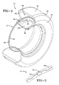
- FIG. 5 illustrates an alternative embodiment of the invention in which a rigid body 54 can be used to locate the splice region in the tire.
- the top surface of the rigid body 54 has a peal off layer of a non-stick material such as Teflon.
- the body 54 itself is composed of a rigid polymeric material of a known type that will bond to rubber.
- the Teflon layer After curing the body in the tire, the Teflon layer provides the same feature as that provided by the sandwich structure described previously. That is, the Teflon layer traps a small amount of air for location.
- the antenna ends 56, 58 may be terminated to electronic connection terminals 60, 52, respectively, within the body 54.
- Mechanical connector posts 64, 66 are further provided in the body 54 and provide the means for engaging electronic package sockets (not shown) whereby establishing an electrical connection between the electronic package and the antenna and a mechanical connection between the electronics package and the body 54.
- the Teflon layer on the top surface of body 54 further protects electronic and mechanical connection terminals incorporated in the rigid body 54 until post application of the electronic device occurs.
- the posts 64, 66 fix the alignment between the tag and body 54 while electrical contact between the antenna and the tag is established via terminals 60, 62.
- the rigid body 54 thus serves to mark the location of the transponder splice region to allow for a post-cure attachment of the transponder tag to body 54.
- the annular apparatus 10 may be created as a unitary assembly and post applied to a tire innerliner by using adhesive.
- the invention reduces the number of materials and process steps required to apply the assembly to tires and the ring assembly is permanently bonded by chemical cross-linking to the tire innerliner.
- the process steps for adhesive application typically involves first assembling and curing the antenna ring and sensor assembly, removing the residual mold release agents from the tire innerliner by using solvents and abrasive grinding, applying adhesive, applying the assembly, stitching, and waiting for the adhesive to cure.
Landscapes
- Engineering & Computer Science (AREA)
- Mechanical Engineering (AREA)
- Arrangements For Transmission Of Measured Signals (AREA)
- Tires In General (AREA)
- Tyre Moulding (AREA)
Abstract
Description
Claims (10)
- A method of manufacturing a tire (12) having a sensor and antenna (32) incorporated therein, the method comprising by the steps of
forming an antenna wire into a predetermined shape having first and second free ends (56, 58);
creating a transponder splice region between the first and second free antenna ends (56, 58);
incorporating transponder splice region identification indicia;
curing the antenna wire into the tire (12) during a tire manufacturing procedure;
locating the transponder splice region by means of the identification indicia; and
splicing the antenna wire ends to the sensor in a post-cure procedure. - The method according to claim 1, wherein the step of incorporating transponder splice region identification indicia comprises overlapping ends of the antenna (32) to form an overlap region (44) and at least partially covering the overlap region (44) with at least one layer (46) of select material that will not bond to the tire (12) compound during a tire curing procedure.
- The method according to claim 1, wherein the step of incorporating transponder splice region identification indicia comprises entrapping an air pocket in the transponder splice region by which to facilitate a post-cure location of the transponder splice region.
- The method according to claim 1, wherein the step of incorporating transponder splice region identification indicia comprises the steps of interposing a junction box between opposed ends of the antenna (32); and terminating opposed ends (56, 58) of the antenna (32) to terminal means within the junction box.
- A sensor-ready tire assembly comprising
an antenna wire (32) formed into a predetermined shape and having first and second free ends (56, 58), the free ends (56, 58) being positioned in an opposed orientation to form a transponder splice region;
a tire (12) having the antenna wire cured therein;
transponder splice region identification indicia means marking the transponder splice region for post-cure location identification. - The sensor-ready tire assembly according to claim 5, wherein the antenna wire is formed into an annular configuration and sheathed within an antenna cover compound.
- The sensor-ready tire assembly according to claim 5 or 6, wherein the transponder splice region identification indicia means comprises at least one layer (46) of a select secondary material covering at least a portion of the transponder splice region.
- The sensor-ready tire assembly according to claim 7, wherein the secondary material is selected from a material that does not bond to the tire (12) during a tire curing procedure.
- The sensor-ready tire assembly of at least one of the previous claims 5-8, including at least one sensor and a communication antenna incorporated therein, the assembly being formed by a process comprising the steps of
forming an antenna wire into a predetermined shape having first and second free ends;
creating a transponder splice region between first and second free antenna ends;
incorporating transponder splice region identification indicia;
curing the antenna wire into the tire during a tire manufacturing procedure;
locating the transponder splice region by means of the transponder splice region identification indicia; and
splicing the antenna wire ends to the sensor in a post-cure procedure. - The sensor-ready tire assembly according to claim 9, wherein the process includes the step of at least partially covering the transponder splice region with at least one layer (46) of select material that will not bond to the tire compound during a tire curing procedure.
Applications Claiming Priority (2)
| Application Number | Priority Date | Filing Date | Title |
|---|---|---|---|
| US744305 | 2003-12-22 | ||
| US10/744,305 US6978669B2 (en) | 2003-12-22 | 2003-12-22 | Method and assembly of sensor ready tires |
Publications (3)
| Publication Number | Publication Date |
|---|---|
| EP1547822A2 true EP1547822A2 (en) | 2005-06-29 |
| EP1547822A3 EP1547822A3 (en) | 2005-07-13 |
| EP1547822B1 EP1547822B1 (en) | 2009-02-11 |
Family
ID=34552845
Family Applications (1)
| Application Number | Title | Priority Date | Filing Date |
|---|---|---|---|
| EP04106685A Expired - Lifetime EP1547822B1 (en) | 2003-12-22 | 2004-12-17 | Method and assembly of sensor ready tires |
Country Status (6)
| Country | Link |
|---|---|
| US (1) | US6978669B2 (en) |
| EP (1) | EP1547822B1 (en) |
| JP (1) | JP4723854B2 (en) |
| BR (1) | BRPI0405787A (en) |
| CA (1) | CA2486273A1 (en) |
| DE (1) | DE602004019385D1 (en) |
Cited By (1)
| Publication number | Priority date | Publication date | Assignee | Title |
|---|---|---|---|---|
| CN109476191A (en) * | 2016-07-28 | 2019-03-15 | 株式会社普利司通 | Pneumatic tires |
Families Citing this family (21)
| Publication number | Priority date | Publication date | Assignee | Title |
|---|---|---|---|---|
| FR2867721A1 (en) * | 2004-03-18 | 2005-09-23 | Michelin Soc Tech | POCKET HOLDING ELECTRONIC SENSOR |
| JP4513412B2 (en) * | 2004-05-10 | 2010-07-28 | 横浜ゴム株式会社 | Wheel information notification system and wheel information notification method |
| US20060043196A1 (en) * | 2004-08-27 | 2006-03-02 | Goodyear Tire And Rubber Company | Air spring mount assembly with identification tag |
| US20070048759A1 (en) * | 2005-06-10 | 2007-03-01 | Dan Luo | Detection of target molecules with labeled nucleic acid detection molecules |
| EP1897078B1 (en) * | 2005-06-10 | 2013-08-07 | Michelin Recherche et Technique S.A. | Inductive coupling of pulses from piezoelectric device |
| US7185534B2 (en) * | 2005-08-03 | 2007-03-06 | The Goodyear Tire & Rubber Company | Ply wire sensor system for a tire |
| US20070222614A1 (en) * | 2006-03-24 | 2007-09-27 | Rapp Patricia A | System and method to monitor wear of an object |
| EP2015942B1 (en) * | 2006-04-26 | 2016-04-06 | Pirelli Tyre S.p.A. | A tyre comprising an electronic unit |
| US20090151828A1 (en) * | 2007-12-15 | 2009-06-18 | Junling Zhao | Tire with antenna encapsulated with rubber compound containing thermoplastic |
| US20090151829A1 (en) * | 2007-12-18 | 2009-06-18 | Robert Edward Lionetti | Tire with integral sensor mount |
| US8082961B2 (en) * | 2007-12-31 | 2011-12-27 | The Goodyear Tire & Rubber Company | Tire with retractable stud |
| US8430142B2 (en) * | 2009-02-25 | 2013-04-30 | The Goodyear Tire & Rubber Company | Environmentally resistant assembly containing an electronic device for use in a tire |
| US8441355B2 (en) * | 2009-10-23 | 2013-05-14 | The Goodyear Tire & Rubber Company | Product and electronic tag assembly |
| US8186985B2 (en) * | 2009-12-17 | 2012-05-29 | The Goodyear Tire & Rubber Company | Mold apparatus for forming grooves in tire shoulder |
| US8949041B2 (en) | 2010-12-02 | 2015-02-03 | Parker-Hannifin Corporation | System and method for monitoring health of a fluid seal member |
| US11143885B2 (en) * | 2017-09-25 | 2021-10-12 | Verily Life Sciences Llc | Smart contact lens with antenna and sensor |
| US11352077B2 (en) * | 2018-12-31 | 2022-06-07 | Contitech Transportbandsysteme Gmbh | Tethered temperature sensor for use in rubber embedded applications |
| US11021021B1 (en) | 2020-12-01 | 2021-06-01 | The Goodyear Tire & Rubber Company | RFID tag secured to a tire |
| WO2023009923A1 (en) | 2021-07-26 | 2023-02-02 | Bridgestone Americas Tire Operations, Llc | Tire with rfid enclosed in different rubber layers and related methods |
| WO2023009922A1 (en) * | 2021-07-26 | 2023-02-02 | Bridgestone Americas Tire Operations, Llc | Tire with rfid surrounded by a rubber layer and related methods |
| US12565066B2 (en) | 2023-10-02 | 2026-03-03 | The Goodyear Tire & Rubber Company | PCB impedance tuning to achieve wideband and high acceptance of coil antenna length variation |
Family Cites Families (14)
| Publication number | Priority date | Publication date | Assignee | Title |
|---|---|---|---|---|
| US4160234A (en) * | 1976-03-29 | 1979-07-03 | Gould Inc. | Abnormal tire condition sensing system |
| US5500065A (en) * | 1994-06-03 | 1996-03-19 | Bridgestone/Firestone, Inc. | Method for embedding a monitoring device within a tire during manufacture |
| WO1999029522A1 (en) * | 1997-12-09 | 1999-06-17 | The Goodyear Tire & Rubber Company | Pneumatic tyre with an antenna for radio transponder |
| CA2312153A1 (en) * | 1997-12-09 | 1999-06-17 | The Goodyear Tire & Rubber Company | Antenna for radio transponder |
| DE69916115T2 (en) * | 1998-08-03 | 2009-10-01 | The Goodyear Tire & Rubber Co., Akron | ASSEMBLY OF TRANSPONDERS IN AIR TIRES |
| US6919799B2 (en) * | 1999-04-29 | 2005-07-19 | Bridgestone/Firestone North American Tire, Llc | Monitoring device and tire combination |
| US6388567B1 (en) | 1999-04-29 | 2002-05-14 | Bridgestone/Firestone North American Tire, Llc | Combination monitoring device and patch for a pneumatic tire and method of installing the same |
| US6474380B1 (en) | 1999-04-29 | 2002-11-05 | Bridgestone/Firestone North American Tire, Llc | Pneumatic tire and monitoring device including dipole antenna |
| GB2364778A (en) | 2000-07-14 | 2002-02-06 | Hypoguard Ltd | Detection of Helicobacter pylori and apparatus therefor |
| DE10159703A1 (en) * | 2001-12-05 | 2003-06-18 | Continental Ag | Method for producing a vehicle tire with a transponder unit |
| US6734791B2 (en) * | 2002-07-31 | 2004-05-11 | Michelin Recherche Et Technique S.A. | Electronics component assembly in a tire for remotely monitoring tire conditions |
| US7138955B2 (en) * | 2003-10-23 | 2006-11-21 | Michelin Recherche Et Technique S.A. | Robust antenna connection for an electronics component assembly in a tire |
| US7017405B2 (en) * | 2003-12-22 | 2006-03-28 | The Goodyear Tire & Rubber Company | System and method for post-cure application of electronics to a tire |
| US20050133132A1 (en) * | 2003-12-23 | 2005-06-23 | Jean-Claude Girard | Apparatus and method for incorporating an annular antenna and electronics into a tire |
-
2003
- 2003-12-22 US US10/744,305 patent/US6978669B2/en not_active Expired - Fee Related
-
2004
- 2004-10-29 CA CA002486273A patent/CA2486273A1/en not_active Abandoned
- 2004-12-15 JP JP2004362512A patent/JP4723854B2/en not_active Expired - Fee Related
- 2004-12-15 BR BR0405787-2A patent/BRPI0405787A/en not_active IP Right Cessation
- 2004-12-17 EP EP04106685A patent/EP1547822B1/en not_active Expired - Lifetime
- 2004-12-17 DE DE602004019385T patent/DE602004019385D1/en not_active Expired - Fee Related
Cited By (2)
| Publication number | Priority date | Publication date | Assignee | Title |
|---|---|---|---|---|
| CN109476191A (en) * | 2016-07-28 | 2019-03-15 | 株式会社普利司通 | Pneumatic tires |
| CN109476191B (en) * | 2016-07-28 | 2020-10-09 | 株式会社普利司通 | Pneumatic tires |
Also Published As
| Publication number | Publication date |
|---|---|
| JP2005178381A (en) | 2005-07-07 |
| EP1547822A3 (en) | 2005-07-13 |
| EP1547822B1 (en) | 2009-02-11 |
| US6978669B2 (en) | 2005-12-27 |
| CA2486273A1 (en) | 2005-06-22 |
| JP4723854B2 (en) | 2011-07-13 |
| DE602004019385D1 (en) | 2009-03-26 |
| US20050132788A1 (en) | 2005-06-23 |
| BRPI0405787A (en) | 2005-09-06 |
Similar Documents
| Publication | Publication Date | Title |
|---|---|---|
| US6978669B2 (en) | Method and assembly of sensor ready tires | |
| US8237553B2 (en) | Method for mounting electronic device and antenna in tire | |
| US6653936B2 (en) | Patch and tire monitoring device | |
| EP1048492B1 (en) | Apparatus and method for providing electrical power to an active electronic device embedded within a tire | |
| US6546982B1 (en) | Mounting transponders in pneumatic tires | |
| EP1550568B1 (en) | System and method for post-cure application of electronics to a tire | |
| JP2000351308A (en) | Dipole antenna for tire tag | |
| AU2002234259A1 (en) | Monitoring device and tire combination | |
| EP1547826B1 (en) | Apparatus and method for incorporating an annular antenna and electronics into a tire | |
| US7736454B2 (en) | Method for incorporating an annular antenna and electronics into a tire |
Legal Events
| Date | Code | Title | Description |
|---|---|---|---|
| PUAI | Public reference made under article 153(3) epc to a published international application that has entered the european phase |
Free format text: ORIGINAL CODE: 0009012 |
|
| PUAL | Search report despatched |
Free format text: ORIGINAL CODE: 0009013 |
|
| AK | Designated contracting states |
Kind code of ref document: A2 Designated state(s): AT BE BG CH CY CZ DE DK EE ES FI FR GB GR HU IE IS IT LI LT LU MC NL PL PT RO SE SI SK TR |
|
| AX | Request for extension of the european patent |
Extension state: AL BA HR LV MK YU |
|
| AK | Designated contracting states |
Kind code of ref document: A3 Designated state(s): AT BE BG CH CY CZ DE DK EE ES FI FR GB GR HU IE IS IT LI LT LU MC NL PL PT RO SE SI SK TR |
|
| AX | Request for extension of the european patent |
Extension state: AL BA HR LV MK YU |
|
| 17P | Request for examination filed |
Effective date: 20060113 |
|
| AKX | Designation fees paid |
Designated state(s): DE FR GB IT |
|
| 17Q | First examination report despatched |
Effective date: 20061123 |
|
| 17Q | First examination report despatched |
Effective date: 20061123 |
|
| GRAP | Despatch of communication of intention to grant a patent |
Free format text: ORIGINAL CODE: EPIDOSNIGR1 |
|
| GRAS | Grant fee paid |
Free format text: ORIGINAL CODE: EPIDOSNIGR3 |
|
| GRAA | (expected) grant |
Free format text: ORIGINAL CODE: 0009210 |
|
| AK | Designated contracting states |
Kind code of ref document: B1 Designated state(s): DE FR GB IT |
|
| REG | Reference to a national code |
Ref country code: GB Ref legal event code: FG4D |
|
| REF | Corresponds to: |
Ref document number: 602004019385 Country of ref document: DE Date of ref document: 20090326 Kind code of ref document: P |
|
| PLBE | No opposition filed within time limit |
Free format text: ORIGINAL CODE: 0009261 |
|
| STAA | Information on the status of an ep patent application or granted ep patent |
Free format text: STATUS: NO OPPOSITION FILED WITHIN TIME LIMIT |
|
| 26N | No opposition filed |
Effective date: 20091112 |
|
| GBPC | Gb: european patent ceased through non-payment of renewal fee |
Effective date: 20091217 |
|
| REG | Reference to a national code |
Ref country code: FR Ref legal event code: ST Effective date: 20100831 |
|
| PG25 | Lapsed in a contracting state [announced via postgrant information from national office to epo] |
Ref country code: FR Free format text: LAPSE BECAUSE OF NON-PAYMENT OF DUE FEES Effective date: 20091231 |
|
| PG25 | Lapsed in a contracting state [announced via postgrant information from national office to epo] |
Ref country code: DE Free format text: LAPSE BECAUSE OF NON-PAYMENT OF DUE FEES Effective date: 20100701 |
|
| PG25 | Lapsed in a contracting state [announced via postgrant information from national office to epo] |
Ref country code: GB Free format text: LAPSE BECAUSE OF NON-PAYMENT OF DUE FEES Effective date: 20091217 |
|
| PG25 | Lapsed in a contracting state [announced via postgrant information from national office to epo] |
Ref country code: IT Free format text: LAPSE BECAUSE OF NON-PAYMENT OF DUE FEES Effective date: 20091217 |