EP1547640B1 - Insertion assisting tool for endoscope and endoscope operating method - Google Patents
Insertion assisting tool for endoscope and endoscope operating method Download PDFInfo
- Publication number
- EP1547640B1 EP1547640B1 EP04030057A EP04030057A EP1547640B1 EP 1547640 B1 EP1547640 B1 EP 1547640B1 EP 04030057 A EP04030057 A EP 04030057A EP 04030057 A EP04030057 A EP 04030057A EP 1547640 B1 EP1547640 B1 EP 1547640B1
- Authority
- EP
- European Patent Office
- Prior art keywords
- air
- balloon
- tube
- endoscope
- assisting tool
- Prior art date
- Legal status (The legal status is an assumption and is not a legal conclusion. Google has not performed a legal analysis and makes no representation as to the accuracy of the status listed.)
- Not-in-force
Links
Images

Classifications
-
- A—HUMAN NECESSITIES
- A61—MEDICAL OR VETERINARY SCIENCE; HYGIENE
- A61B—DIAGNOSIS; SURGERY; IDENTIFICATION
- A61B1/00—Instruments for performing medical examinations of the interior of cavities or tubes of the body by visual or photographical inspection, e.g. endoscopes; Illuminating arrangements therefor
- A61B1/31—Instruments for performing medical examinations of the interior of cavities or tubes of the body by visual or photographical inspection, e.g. endoscopes; Illuminating arrangements therefor for the rectum, e.g. proctoscopes, sigmoidoscopes, colonoscopes
-
- A—HUMAN NECESSITIES
- A61—MEDICAL OR VETERINARY SCIENCE; HYGIENE
- A61B—DIAGNOSIS; SURGERY; IDENTIFICATION
- A61B1/00—Instruments for performing medical examinations of the interior of cavities or tubes of the body by visual or photographical inspection, e.g. endoscopes; Illuminating arrangements therefor
- A61B1/00064—Constructional details of the endoscope body
- A61B1/00071—Insertion part of the endoscope body
- A61B1/0008—Insertion part of the endoscope body characterised by distal tip features
- A61B1/00082—Balloons
-
- A—HUMAN NECESSITIES
- A61—MEDICAL OR VETERINARY SCIENCE; HYGIENE
- A61B—DIAGNOSIS; SURGERY; IDENTIFICATION
- A61B1/00—Instruments for performing medical examinations of the interior of cavities or tubes of the body by visual or photographical inspection, e.g. endoscopes; Illuminating arrangements therefor
- A61B1/00147—Holding or positioning arrangements
- A61B1/00154—Holding or positioning arrangements using guiding arrangements for insertion
-
- A—HUMAN NECESSITIES
- A61—MEDICAL OR VETERINARY SCIENCE; HYGIENE
- A61B—DIAGNOSIS; SURGERY; IDENTIFICATION
- A61B1/00—Instruments for performing medical examinations of the interior of cavities or tubes of the body by visual or photographical inspection, e.g. endoscopes; Illuminating arrangements therefor
- A61B1/005—Flexible endoscopes
- A61B1/01—Guiding arrangements therefore
-
- A—HUMAN NECESSITIES
- A61—MEDICAL OR VETERINARY SCIENCE; HYGIENE
- A61B—DIAGNOSIS; SURGERY; IDENTIFICATION
- A61B1/00—Instruments for performing medical examinations of the interior of cavities or tubes of the body by visual or photographical inspection, e.g. endoscopes; Illuminating arrangements therefor
- A61B1/12—Instruments for performing medical examinations of the interior of cavities or tubes of the body by visual or photographical inspection, e.g. endoscopes; Illuminating arrangements therefor with cooling or rinsing arrangements
-
- A—HUMAN NECESSITIES
- A61—MEDICAL OR VETERINARY SCIENCE; HYGIENE
- A61M—DEVICES FOR INTRODUCING MEDIA INTO, OR ONTO, THE BODY; DEVICES FOR TRANSDUCING BODY MEDIA OR FOR TAKING MEDIA FROM THE BODY; DEVICES FOR PRODUCING OR ENDING SLEEP OR STUPOR
- A61M25/00—Catheters; Hollow probes
- A61M25/01—Introducing, guiding, advancing, emplacing or holding catheters
- A61M25/06—Body-piercing guide needles or the like
- A61M25/0662—Guide tubes
-
- A—HUMAN NECESSITIES
- A61—MEDICAL OR VETERINARY SCIENCE; HYGIENE
- A61M—DEVICES FOR INTRODUCING MEDIA INTO, OR ONTO, THE BODY; DEVICES FOR TRANSDUCING BODY MEDIA OR FOR TAKING MEDIA FROM THE BODY; DEVICES FOR PRODUCING OR ENDING SLEEP OR STUPOR
- A61M25/00—Catheters; Hollow probes
- A61M25/10—Balloon catheters
Definitions
- the present invention relates to an insertion assisting tool including a balloon at an tip end outer peripheral portion for an endoscope, comprising an endoscope insertion section and being suitable for guiding the endoscope insertion section into a body cavity.
- an endoscope apparatus which prevents excessive bending and deflection of the insertion section by inserting the insertion section into a body cavity with an insertion assisting tool called an over tube or a sliding tube attached to the insertion section of the endoscope, and guiding the insertion section with this insertion assisting tool (for example, Japanese Patent Application Publication No. 10-248794 ).
- a double balloon type endoscope apparatus disclosed in Japanese Patent Application Publication No. 2002-301019 includes an endoscope with a first inflatable and deflatable balloon attached to a tip end outer peripheral portion of an endoscope insertion section, and an over tube which serves as a guide at the time of insertion of the insertion section, with a second inflatable and deflatable balloon attached to the tip end peripheral portion, and the endoscope insertion section inserted into the over tube.
- This double balloon type endoscope apparatus is for inserting the endoscope insertion section into a deep part of an alimentary canal by carrying out an inserting operation of the over tube and the endoscope insertion section and the inflation and deflation operations of the first and the second balloons in accordance with a predetermined procedure.
- JP-10155733 The device known from JP-10155733 is regarded as closest prior art.
- the double balloon type endoscope apparatus in Japanese Patent Application Publication No. 2002-301019 has the problem that when, for example, the second balloon is inflated and closely fitted to the intestinal wall and thereafter, an operation of moving the over tube in the extracting direction is performed, the over tube cannot be smoothly moved. Namely, this is considered to result from addition of compression to the air stored at a base end part side of the over tube with respect to the second balloon (air stored in a gap between the over tube and the intestinal wall) by the operation of the over tube, and the air pressure caused by this gives a difficulty to the extracting operation of the over tube.
- the present invention is made in view of the above circumstances, and has its object to provide an insertion assisting tool for an endoscope and an endoscope operation method capable of smoothly performing an extracting operation of the insertion assisting tool in the state in which a balloon of the insertion assisting tool is inflated.
- a first aspect of the present invention is an insertion assisting tool for an endoscope according to claim 1.
- the air stored in the gap between the insertion assisting tool and the intestinal wall flows from the air hole of the insertion assisting tool, and is discharged to the outside via the insertion assisting tool.
- the air in the intestinal space sealed between the balloon of the insertion assisting tool and the balloon at the tip end of the endoscope insertion section is discharged to the outside from the air hole via the insertion assisting tool when the air pressure is to rise. Accordingly, air pressure rise in the intestinal space can be prevented, and therefore, influence on the intestinal wall by the air pressure rise can be eliminated.
- the air hole is formed at an outer periphery and/or the tip end part of the insertion assisting tool, and therefore, the extracting operation of the insertion assisting tool in the state in which the balloon of the insertion assisting tool is inflated can be performed smoothly.
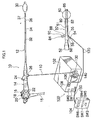
- Fig. 1 shows a system schematic diagram of an endoscope apparatus to which an insertion assisting tool according to the present invention is applied.
- the endoscope apparatus shown in the drawing is constructed by an endoscope 10, an over tube (corresponding to the insertion assisting tool) 50, and a balloon control device 100.
- the endoscope 10 includes a hand operation section 14, and an insertion section 12 connected to the hand operation section 14.
- a universal cable 15 is connected to the hand operation section 14, and a connecter (not shown) connected to a processor and a light source device not shown is provided at a tip end of the universal cable 15.
- An air/water passing button 16, a suction button 18, and a shutter button 20 which are operated by an operator are provided in parallel on the hand operation section 14, and a pair of angle knobs 22 and 22, and the forceps insertion part 24 are provided respectively at predetermined positions.
- the hand operation section 14 is provided with a balloon air port 26 for supplying air to a first balloon 30 and sucking air from the first balloon 30.
- the insertion section 12 is constructed by a flexible part 32, a curving part 34 and a tip end rigid part 36.
- the curving part 34 is constructed by connecting a plurality of node rings to be able to curve, and is remotely operated to curve by the rotational operation of a pair of angle knobs 22 and 22 provided on the hand operation section 14. Thereby, a tip end surface 37 of the tip end rigid part 36 can be faced in a desired direction.
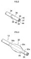
- the tip end surface 37 of the tip end rigid part 36 is provided with an object optical system 38, an illumination lens 40, air/water passing nozzle 42, a forceps port 44 and the like in predetermined positions.
- An air supply/suction port 28 is provided on an outer peripheral surface of the tip end rigid part 36, and this air supply/suction port 28 communicates with the balloon air port 26 in Fig. 1 via an air supply tube (not shown) with an inner diameter of about 0.8 mm which is inserted into the insertion section 12.
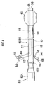
- the first balloon 30 constituted of an elastic body such as rubber is detachably attached to the tip end rigid part 36 of the insertion section 12.
- the fist balloon 30 is formed by a bulging portion 30c in a center and attaching portions 30a and 30b at both ends of the bulging portion 30c, and is attached to the tip end rigid part 36 side so that the air supply/suction port 28 is located inside the bulging portion 30c as shown in Fig. 3 .
- the attaching portions 30a and 30b are formed to have smaller diameters than the diameter of the tip end rigid portion 36, and after being closely fitted onto the tip end part 36 with their elastic forces, the attaching portions 30a and 30b are fixed with threads not shown wound around the attaching portions 30a and 30b.
- the fixation is not limited to the thread winding fixation, but the attaching portions 30a and 30b may be fixed to the tip end rigid part 36 by fitting fixing rings onto the attaching portions 30a and 30b.
- the first balloon 30 fitted onto the tip end rigid part 36 has its bulging portion 30c inflated in a substantially spherical shape by blowing air from the air supply/suction port 28 shown in Fig. 2 .
- the bulging portion 30c is deflated and is closely fitted onto the outer peripheral surface of the tip end rigid part 36.
- the over tube 50 shown in Fig. 1 is constructed by a tube body 51, and a gripping part 52.
- the tube body 51 is formed into a cylindrical shape and has a slightly larger inner diameter than an outer diameter of the insertion section 12, as shown in Figs. 4 and 5 .
- the tube body 51 is constructed by covering an outer side of a flexible resin tube made of urethane or the like with lubricating coat and covering an inner side with the lubricating coat.
- the gripping part 52 is formed into a cylindrical shape as shown in Fig. 4 , and constructed by a body portion 52A having a large diameter which is gripped by an operator, and a connecting portion 52B fitted onto the base end part of the tube body 51.
- the insertion section 12 of the endoscope 10 shown in Fig. 1 is inserted toward the tube body 51 from the body portion 52A of the gripping part 52 shown in Fig. 4 .
- a balloon air port 54 is provided at the base end side of the tube body 51.
- An air supply tube 56 with an inner diameter of about 1 mm is connected to the balloon air port 54, and this tube 56 is bonded to an outer peripheral surface of the tube body 51 and is provided to extend to a tip end portion of the tube body 51 as shown in Fig. 5 .
- a tip end 58 of the tube body 51 is formed into a tapered shape.
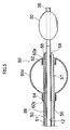
- a second balloon 60 constituted of an elastic body such as rubber is fitted onto the base end side of the tip end 58 of the tube body 51.
- the second balloon 60 is fitted in the state in which the tube body 51 penetrates through the balloon 60 as shown in Fig. 5 , and is constructed by a bulging portion 60c in a center, and attaching portions 60a and 60b at both ends of the bulging portion 60c.
- the attaching portion 60a at the tip end side is folded back to the inside of the bulging portion 60c, and the attaching portion 60a folded back is fixed to the tube body 51 with an X-ray contrast thread 62 wound around the attaching portion 60a which is folded back.
- the attaching portion 60b at the base end side is disposed outside the second balloon 60, and is fixed to the tube body 51 with a thread 64 wound around the attaching portion 60b.
- the bulging portion 60c is formed into a substantially spherical shape in a natural state (the state in which the bulging portion 60c does not inflate or deflate), and as for the size, the bulging portion 60c is formed to be larger than the size of the first balloon 30 in a natural state (the state in which the balloon 30 does not inflate or deflate). Accordingly, when the air is supplied to the first balloon 30 and the second balloon 60 at the same pressure, the outer diameter of the bulging portion 60c of the second balloon 60 becomes larger than the outer diameter of the bulging portion 30c of the first balloon 30.
- the outer diameter of the second balloon 60 is constructed so as to be ⁇ 50 mm when the outer diameter of the first balloon 30 is ⁇ 25 mm, for example.
- the aforementioned tube 56 is opened in the inside of the bulging portion 60c, and the opening is formed as an air supply/suction port 57. Accordingly, when air is supplied from the balloon air port 54, the air is blown from the air supply/suction port 57 and thereby, the bulging portion 60c is inflated. When air is sucked from the balloon air port 54, the air is sucked from the air supply/suction portion 57, and the second balloon 60 is deflated.
- Reference numeral 66 in Fig. 4 designates an inlet port for filling a lubricating liquid such as water into the tube body 51, and the inlet port 66 communicates with the base end part side of the tube body 51 via a tube 68 with a thin diameter.
- an air release hole (air hole) 80 is formed at a base end part side from the second balloon attaching position of the tube body 51.
- This air release hole 80 is opened as a suction hole 84 at the base end part of the tube body 51 via an air tube 82 integrally formed at or bonded to the tube body 51.
- the air release hole 80 is formed at only one location, but a plurality of air release holes 80 may be formed, and the forming position may be any position if only it is at the base end part side from the second balloon attaching position.
- This air release hole 80 has the function of releasing air stored between the tube body 51 and the intestinal canal (not shown), and therefore, it is preferable to form the air release holes 80 equidistantly around the tube body 51 and at equal spaces in the axial direction.
- an air release hole (air hole) 86 is formed at the tip end part side from the second balloon attaching position of the tube body 511.
- This air release hole 86 is opened at the base end part of the tube body 51 as a suction port 90 via an air tube 88 integrally formed at or bonded to the tube body 51.
- the air in an intestinal space sealed between the second balloon 60 and the first balloon 30 is discharged from the air release hole 86 to outside air from the suction port 90 at the base end part of the tube body 51 via the air tube 88.
- the balloon control device 100 in Fig. 1 is the device which supplies and sucks fluid such as air to and from the first balloon 30, and supplies and sucks fluid such as air to and from the second balloon 60.
- the balloon control device 100 is constructed by a device body 102 including a pump, sequencer and the like not shown, and a hand switch 104 for remote control.
- a front panel of the device body 102 is provided with a power supply switch SW1, a stop switch SW2, a pressure gauge 106 for the first balloon 30 and a pressure gauge 108 for the second balloon 60.
- a tube 110 for supplying/sucking air to and from the first balloon 30, and a tube 120 for supplying/sucking air to and from the second balloon 60 are attached to the front panel of the device body 102.
- Liquid storing tanks 130 and 140 for storing body fluid, which flows backward from the first balloon 30 and the second balloon 60 when the first balloon 30 and the second balloon 60 are broken, are respectively provided at midpoints of the respective tubes 110 and 120.
- the hand switch 104 is provided with a similar stop switch SW3 to the stop switch SW2 at the side of the device body 102, an ON/OFF switch SW4 for supporting pressurization/decompression of the first balloon 30, a pose switch SW5 for keeping the pressure of the first balloon 30, an ON/OFF switch SW6 for supporting pressurization/decompression of the second balloon 60, and a pose switch SW7 for keeping the pressure of the second balloon 60.
- This hand switch 104 is electrically connected to the device body 102 via a cable 150.
- the balloon control device 100 which is constructed as above supplies air to the first balloon 30 and the second balloon 60 and inflates the first balloon 30 and the second balloon 60, and controls the air pressure at a fixed value to keep the first balloon 30 and the second balloon 60 in the inflated state.
- the balloon control device 100 sucks air from the first balloon 30 and the second balloon 60 and deflates the first balloon 30 and the second balloon 60, and controls the air pressure at a fixed value to keep the first balloon 30 and the second balloon 60 in the deflated state.
- the insertion section 12 is inserted into an intestinal canal (for example, descending limb of duodenum) 70 in the state in which the over tube 50 covers the insertion section 12.
- an intestinal canal for example, descending limb of duodenum
- the first balloon 30 and the second balloon 60 are deflated.
- Fig. 6C only the insertion section 12 of the endoscope 10 is inserted to a deep part of the intestinal canal 70 with the over tube 50 as a guide.
- Fig. 6D air is supplied to the first balloon 30 to inflate the first balloon 30.
- the first balloon 30 is closely fitted and fixed to the intestinal canal 70.
- the first balloon 30 is smaller in the size at the time of inflation than the second balloon 60, and therefore the burden exerted on the intestinal canal 70 is small, thus making it possible to prevent damage to the intestinal canal 70.
- the over tube 50 is pushed in, and inserted along the insertion section 12, as shown in Fig. 6E .
- air is supplied to the second balloon 60 to inflate the second balloon 60 as shown in Fig. 6F .
- the second balloon 60 is closely fitted and fixed to the intestinal canal 70. Namely, the intestinal canal 70 is gripped by the second balloon 60.
- the operation of drawing in the intestinal canal 70 by operating the over tube 50 in the drawing direction is performed.
- the intestinal canal 70 contracts substantially straight, and excessive deflection and bending of the over tube 50 are eliminated.
- both the first balloon 30 and the second balloon 60 are caught in the intestinal canal 70, but the friction resistance of the first balloon 30 is smaller than the friction resistance of the second balloon 60. Therefore, even if the first balloon 30 and the second balloon 60 move to separate from each other, the first balloon 30 with small friction resistance slides with respect to the intestinal canal 70, and therefore, it does not happen that the intestinal canal 70 is damaged by being pulled by both the balloons 30 and 60.
- the air stored in the gap between the tube body 51 and the intestinal wall flows in from the air release hole 80 (see Fig. 4 ) of the tube body 51, and is discharged to the outside air from the suction port 84 formed at the base end part of the tube body 51 via the air tube 82.
- the stored air can be discharged by opening the suction port 84 to atmosphere, but a manual suction tool such as an injector is connected to the suction port 84, and the air may be forcefully discharged by the manual suction tool.
- the tip end rigid part 36 of the insertion section 12 is inserted into as deep a part of the intestinal canal 70 as possible. Namely, the inserting operation as shown in Fig. 6C is performed again. Thereby, the tip end rigid part 36 of the insertion section 12 can be inserted into a deep part of the intestinal canal 70.
- the pushing operation as shown in Fig. 6E is performed after the fixing operation as shown in Fig. 6D is performed, the gripping operation as shown in Fig. 6F and the drawing operation as shown in Fig. 6G , and the inserting operation as shown in Fig. 6H are repeatedly performed in sequence.
- the insertion section 12 can be further inserted into a deep part of the intestinal canal 70.
- the air release hole 86 is formed at the tip end part side from the second balloon attaching position of the tube body 51, and therefore, when the air pressure in the sealed intestinal space between the second balloon 60 and the first balloon 30 is to rise during the above operation, the air in the intestinal space is discharged from the air release hole 86 to the outside air from the suction port 90 formed at the base end part of the tube body 51. Accordingly, rise in the air pressure in the intestinal space can be prevented, and therefore, influence on the intestinal wall by the rise in the air pressure can be eliminated.
- the operation method of the endoscope apparatus there is the operation method of inserting the insertion section 12 and the over tube 50 into the intestinal canal 70 while inflating the intestinal canal 70 by injecting air from the air/water passing nozzle 42 after inserting the endoscope insertion section 12 into the intestine canal 70.
- the air stored in the intestinal canal 70 can be discharged from the air release hole 86 according to the over tube 50 in which the air release hole 86 is formed at the tip end part side of the tube body 51 of the over tube 50, and therefore, storing of air at the time of drawing in the intestinal canal 70 can be prevented.
- the over tube 50 is shown as an example as the insertion assisting tool, but the present invention is not limited to this, and a sliding tube which is inserted per anus can be used.
Abstract
Description
- The present invention relates to an insertion assisting tool including a balloon at an tip end outer peripheral portion for an endoscope, comprising an endoscope insertion section and being suitable for guiding the endoscope insertion section into a body cavity.
- When the insertion section of an endoscope is inserted into a deep alimentary canal such as a small intestine, by only pushing the insertion section into the deep alimentary canal, the force is difficult to transmit to a tip end of the insertion section due to complicated bending of an intestinal canal, and insertion into a deep part is difficult. Namely, if excessive bending and deflection occur to the insertion section, it is difficult to insert the insertion section further into a deeper part. Thus, there is proposed an endoscope apparatus which prevents excessive bending and deflection of the insertion section by inserting the insertion section into a body cavity with an insertion assisting tool called an over tube or a sliding tube attached to the insertion section of the endoscope, and guiding the insertion section with this insertion assisting tool (for example,
Japanese Patent Application Publication No. 10-248794 - Meanwhile, a double balloon type endoscope apparatus disclosed in
Japanese Patent Application Publication No. 2002-301019 - The device known from
JP-10155733 - However, the double balloon type endoscope apparatus in
Japanese Patent Application Publication No. 2002-301019 - The present invention is made in view of the above circumstances, and has its object to provide an insertion assisting tool for an endoscope and an endoscope operation method capable of smoothly performing an extracting operation of the insertion assisting tool in the state in which a balloon of the insertion assisting tool is inflated.
- In order to attain the above-described object, a first aspect of the present invention is an insertion assisting tool for an endoscope according to
claim 1. - According to the present invention, when the extracting operation of the insertion assisting tool in the state in which the balloon of the insertion assisting tool is inflated, the air stored in the gap between the insertion assisting tool and the intestinal wall flows from the air hole of the insertion assisting tool, and is discharged to the outside via the insertion assisting tool. Thereby, at the time of extracting operation of the insertion assisting tool, the air pressure is not exerted on the insertion assisting tool, and therefore, the extracting operation of the insertion assisting tool can be performed smoothly.
- According to the present invention, the air in the intestinal space sealed between the balloon of the insertion assisting tool and the balloon at the tip end of the endoscope insertion section is discharged to the outside from the air hole via the insertion assisting tool when the air pressure is to rise. Accordingly, air pressure rise in the intestinal space can be prevented, and therefore, influence on the intestinal wall by the air pressure rise can be eliminated.
- According to the insertion assisting tool for an endoscope and the endoscope operating method according to the present invention, the air hole is formed at an outer periphery and/or the tip end part of the insertion assisting tool, and therefore, the extracting operation of the insertion assisting tool in the state in which the balloon of the insertion assisting tool is inflated can be performed smoothly.
-
-
Fig. 1 is a system schematic diagram of an endoscope apparatus to which an over tube according to the present invention is applied; -
Fig. 2 is a perspective view showing a tip end part of an insertion section of an endoscope; -
Fig. 3 is a perspective view showing the tip end rigid part of the insertion section onto which a first balloon is fitted; -
Fig. 4 is a side view of an over tube; -
Fig. 5 is a sectional side view showing a tip end part of the over tube through which the insertion section is inserted; and -
Figs. 6A to 6H are explanatory views showing an operation method of the endoscope apparatus shown inFig. 1 . - A preferred embodiment of an insertion assisting tool for an endoscope according to the present invention will be explained in accordance with the following attached drawings. As an example, an endoscope operation method is shown too.
-
Fig. 1 shows a system schematic diagram of an endoscope apparatus to which an insertion assisting tool according to the present invention is applied. The endoscope apparatus shown in the drawing is constructed by anendoscope 10, an over tube (corresponding to the insertion assisting tool) 50, and aballoon control device 100. - The
endoscope 10 includes ahand operation section 14, and aninsertion section 12 connected to thehand operation section 14. Auniversal cable 15 is connected to thehand operation section 14, and a connecter (not shown) connected to a processor and a light source device not shown is provided at a tip end of theuniversal cable 15. - An air/
water passing button 16, a suction button 18, and a shutter button 20 which are operated by an operator are provided in parallel on thehand operation section 14, and a pair ofangle knobs forceps insertion part 24 are provided respectively at predetermined positions. Further, thehand operation section 14 is provided with aballoon air port 26 for supplying air to afirst balloon 30 and sucking air from thefirst balloon 30. - The
insertion section 12 is constructed by aflexible part 32, acurving part 34 and a tip endrigid part 36. The curvingpart 34 is constructed by connecting a plurality of node rings to be able to curve, and is remotely operated to curve by the rotational operation of a pair ofangle knobs hand operation section 14. Thereby, atip end surface 37 of the tip endrigid part 36 can be faced in a desired direction. - As shown in
Fig. 2 , thetip end surface 37 of the tip endrigid part 36 is provided with an objectoptical system 38, anillumination lens 40, air/water passing nozzle 42, aforceps port 44 and the like in predetermined positions. An air supply/suction port 28 is provided on an outer peripheral surface of the tip endrigid part 36, and this air supply/suction port 28 communicates with theballoon air port 26 inFig. 1 via an air supply tube (not shown) with an inner diameter of about 0.8 mm which is inserted into theinsertion section 12. Accordingly, air is blown out of the air supply/suction port 28 of the tip endrigid part 36 by supplying air to theballoon air port 26, and on the other hand, air is sucked from the air supply/suction port 28 by sucking air from theballoon air port 26. - As shown in
Fig. 1 , thefirst balloon 30 constituted of an elastic body such as rubber is detachably attached to the tip endrigid part 36 of theinsertion section 12. Thefist balloon 30 is formed by a bulgingportion 30c in a center and attachingportions portion 30c, and is attached to the tip endrigid part 36 side so that the air supply/suction port 28 is located inside the bulgingportion 30c as shown inFig. 3 . The attachingportions rigid portion 36, and after being closely fitted onto thetip end part 36 with their elastic forces, the attachingportions portions portions rigid part 36 by fitting fixing rings onto the attachingportions - The
first balloon 30 fitted onto the tip endrigid part 36 has its bulgingportion 30c inflated in a substantially spherical shape by blowing air from the air supply/suction port 28 shown inFig. 2 . On the other hand, by sucking air from the air supply/suction port 28, the bulgingportion 30c is deflated and is closely fitted onto the outer peripheral surface of the tip endrigid part 36. - The
over tube 50 shown inFig. 1 is constructed by atube body 51, and agripping part 52. Thetube body 51 is formed into a cylindrical shape and has a slightly larger inner diameter than an outer diameter of theinsertion section 12, as shown inFigs. 4 and5 . Thetube body 51 is constructed by covering an outer side of a flexible resin tube made of urethane or the like with lubricating coat and covering an inner side with the lubricating coat. - The
gripping part 52 is formed into a cylindrical shape as shown inFig. 4 , and constructed by abody portion 52A having a large diameter which is gripped by an operator, and a connectingportion 52B fitted onto the base end part of thetube body 51. Theinsertion section 12 of theendoscope 10 shown inFig. 1 is inserted toward thetube body 51 from thebody portion 52A of thegripping part 52 shown inFig. 4 . - A
balloon air port 54 is provided at the base end side of thetube body 51. Anair supply tube 56 with an inner diameter of about 1 mm is connected to theballoon air port 54, and thistube 56 is bonded to an outer peripheral surface of thetube body 51 and is provided to extend to a tip end portion of thetube body 51 as shown inFig. 5 . - A
tip end 58 of thetube body 51 is formed into a tapered shape. Asecond balloon 60 constituted of an elastic body such as rubber is fitted onto the base end side of thetip end 58 of thetube body 51. Thesecond balloon 60 is fitted in the state in which thetube body 51 penetrates through theballoon 60 as shown inFig. 5 , and is constructed by a bulgingportion 60c in a center, and attachingportions portion 60c. The attachingportion 60a at the tip end side is folded back to the inside of the bulgingportion 60c, and the attachingportion 60a folded back is fixed to thetube body 51 with anX-ray contrast thread 62 wound around the attachingportion 60a which is folded back. The attachingportion 60b at the base end side is disposed outside thesecond balloon 60, and is fixed to thetube body 51 with athread 64 wound around the attachingportion 60b. - The bulging
portion 60c is formed into a substantially spherical shape in a natural state (the state in which the bulgingportion 60c does not inflate or deflate), and as for the size, the bulgingportion 60c is formed to be larger than the size of thefirst balloon 30 in a natural state (the state in which theballoon 30 does not inflate or deflate). Accordingly, when the air is supplied to thefirst balloon 30 and thesecond balloon 60 at the same pressure, the outer diameter of the bulgingportion 60c of thesecond balloon 60 becomes larger than the outer diameter of the bulgingportion 30c of thefirst balloon 30. The outer diameter of thesecond balloon 60 is constructed so as to be φ50 mm when the outer diameter of thefirst balloon 30 is φ25 mm, for example. - The
aforementioned tube 56 is opened in the inside of the bulgingportion 60c, and the opening is formed as an air supply/suction port 57. Accordingly, when air is supplied from theballoon air port 54, the air is blown from the air supply/suction port 57 and thereby, the bulgingportion 60c is inflated. When air is sucked from theballoon air port 54, the air is sucked from the air supply/suction portion 57, and thesecond balloon 60 is deflated. -
Reference numeral 66 inFig. 4 designates an inlet port for filling a lubricating liquid such as water into thetube body 51, and theinlet port 66 communicates with the base end part side of thetube body 51 via atube 68 with a thin diameter. - Incidentally, in the over
tube 50 in this embodiment, an air release hole (air hole) 80 is formed at a base end part side from the second balloon attaching position of thetube body 51. Thisair release hole 80 is opened as asuction hole 84 at the base end part of thetube body 51 via anair tube 82 integrally formed at or bonded to thetube body 51. In the overtube 50 shown inFig. 4 , the example in which theair release hole 80 is formed at only one location, but a plurality of air release holes 80 may be formed, and the forming position may be any position if only it is at the base end part side from the second balloon attaching position. Thisair release hole 80 has the function of releasing air stored between thetube body 51 and the intestinal canal (not shown), and therefore, it is preferable to form the air release holes 80 equidistantly around thetube body 51 and at equal spaces in the axial direction. - In the over
tube 50, an air release hole (air hole) 86 is formed at the tip end part side from the second balloon attaching position of the tube body 511. Thisair release hole 86 is opened at the base end part of thetube body 51 as asuction port 90 via anair tube 88 integrally formed at or bonded to thetube body 51. As a result, the air in an intestinal space sealed between thesecond balloon 60 and thefirst balloon 30 is discharged from theair release hole 86 to outside air from thesuction port 90 at the base end part of thetube body 51 via theair tube 88. - Meanwhile, the
balloon control device 100 inFig. 1 is the device which supplies and sucks fluid such as air to and from thefirst balloon 30, and supplies and sucks fluid such as air to and from thesecond balloon 60. Theballoon control device 100 is constructed by adevice body 102 including a pump, sequencer and the like not shown, and ahand switch 104 for remote control. - A front panel of the
device body 102 is provided with a power supply switch SW1, a stop switch SW2, apressure gauge 106 for thefirst balloon 30 and apressure gauge 108 for thesecond balloon 60. Atube 110 for supplying/sucking air to and from thefirst balloon 30, and atube 120 for supplying/sucking air to and from thesecond balloon 60 are attached to the front panel of thedevice body 102.Liquid storing tanks first balloon 30 and thesecond balloon 60 when thefirst balloon 30 and thesecond balloon 60 are broken, are respectively provided at midpoints of therespective tubes - Meanwhile, the
hand switch 104 is provided with a similar stop switch SW3 to the stop switch SW2 at the side of thedevice body 102, an ON/OFF switch SW4 for supporting pressurization/decompression of thefirst balloon 30, a pose switch SW5 for keeping the pressure of thefirst balloon 30, an ON/OFF switch SW6 for supporting pressurization/decompression of thesecond balloon 60, and a pose switch SW7 for keeping the pressure of thesecond balloon 60. Thishand switch 104 is electrically connected to thedevice body 102 via a cable 150. - The
balloon control device 100 which is constructed as above supplies air to thefirst balloon 30 and thesecond balloon 60 and inflates thefirst balloon 30 and thesecond balloon 60, and controls the air pressure at a fixed value to keep thefirst balloon 30 and thesecond balloon 60 in the inflated state. Theballoon control device 100 sucks air from thefirst balloon 30 and thesecond balloon 60 and deflates thefirst balloon 30 and thesecond balloon 60, and controls the air pressure at a fixed value to keep thefirst balloon 30 and thesecond balloon 60 in the deflated state. - Next, an operation method of the endoscope apparatus will be explained in accordance with
Figs. 6A to 6H . This method does not fall within the scope of the invention. - First, as shown in
Fig. 6A , theinsertion section 12 is inserted into an intestinal canal (for example, descending limb of duodenum) 70 in the state in which the overtube 50 covers theinsertion section 12. At this time, thefirst balloon 30 and thesecond balloon 60 are deflated. - Next, as shown in
Fig. 6B , in the state in which thetip end 58 of theover tube 50 is inserted into a bent portion of theintestinal canal 70, air is supplied to thesecond balloon 60 to inflate thesecond balloon 60. As a result, thesecond balloon 60 is closely fitted to and caught by theintestinal canal 70, and thetip end 58 of theover tube 50 is fixed to theintestinal canal 70. - Next, as shown in
Fig. 6C , only theinsertion section 12 of theendoscope 10 is inserted to a deep part of theintestinal canal 70 with the overtube 50 as a guide. Then, as shown inFig. 6D , air is supplied to thefirst balloon 30 to inflate thefirst balloon 30. As a result, thefirst balloon 30 is closely fitted and fixed to theintestinal canal 70. In this case, thefirst balloon 30 is smaller in the size at the time of inflation than thesecond balloon 60, and therefore the burden exerted on theintestinal canal 70 is small, thus making it possible to prevent damage to theintestinal canal 70. - Next, after air is sucked from the
second balloon 60 to deflate thesecond balloon 60, the overtube 50 is pushed in, and inserted along theinsertion section 12, as shown inFig. 6E . Then, after thetip end 58 of theover tube 50 is pushed into the vicinity of thefirst balloon 30, air is supplied to thesecond balloon 60 to inflate thesecond balloon 60 as shown inFig. 6F . As a result, thesecond balloon 60 is closely fitted and fixed to theintestinal canal 70. Namely, theintestinal canal 70 is gripped by thesecond balloon 60. - Next, as shown in
Fig. 6G , the operation of drawing in theintestinal canal 70 by operating the overtube 50 in the drawing direction is performed. Thereby, theintestinal canal 70 contracts substantially straight, and excessive deflection and bending of theover tube 50 are eliminated. When the overtube 50 is drawn in at this time, both thefirst balloon 30 and thesecond balloon 60 are caught in theintestinal canal 70, but the friction resistance of thefirst balloon 30 is smaller than the friction resistance of thesecond balloon 60. Therefore, even if thefirst balloon 30 and thesecond balloon 60 move to separate from each other, thefirst balloon 30 with small friction resistance slides with respect to theintestinal canal 70, and therefore, it does not happen that theintestinal canal 70 is damaged by being pulled by both theballoons - At this time, the air stored in the gap between the
tube body 51 and the intestinal wall flows in from the air release hole 80 (seeFig. 4 ) of thetube body 51, and is discharged to the outside air from thesuction port 84 formed at the base end part of thetube body 51 via theair tube 82. As a result, at the time of the operation of theover tube 50 in the drawing direction, the air pressure occurring as a result that the air stored in the gap between theover tube 50 and the intestinal wall is compressed is not exerted on the overtube 50, and therefore, the operation of theover tube 50 in the drawing direction can be performed smoothly. The stored air can be discharged by opening thesuction port 84 to atmosphere, but a manual suction tool such as an injector is connected to thesuction port 84, and the air may be forcefully discharged by the manual suction tool. - Next, as shown in
Fig. 6H , air is sucked from thefirst balloon 30 to deflate thefirst balloon 30. Then, the tip endrigid part 36 of theinsertion section 12 is inserted into as deep a part of theintestinal canal 70 as possible. Namely, the inserting operation as shown inFig. 6C is performed again. Thereby, the tip endrigid part 36 of theinsertion section 12 can be inserted into a deep part of theintestinal canal 70. When theinsertion section 12 is further inserted into a deep part, the pushing operation as shown inFig. 6E is performed after the fixing operation as shown inFig. 6D is performed, the gripping operation as shown inFig. 6F and the drawing operation as shown inFig. 6G , and the inserting operation as shown inFig. 6H are repeatedly performed in sequence. Thus, theinsertion section 12 can be further inserted into a deep part of theintestinal canal 70. - In the over
tube 50 of the example, theair release hole 86 is formed at the tip end part side from the second balloon attaching position of thetube body 51, and therefore, when the air pressure in the sealed intestinal space between thesecond balloon 60 and thefirst balloon 30 is to rise during the above operation, the air in the intestinal space is discharged from theair release hole 86 to the outside air from thesuction port 90 formed at the base end part of thetube body 51. Accordingly, rise in the air pressure in the intestinal space can be prevented, and therefore, influence on the intestinal wall by the rise in the air pressure can be eliminated. - As an example of the operation method of the endoscope apparatus, there is the operation method of inserting the
insertion section 12 and the overtube 50 into theintestinal canal 70 while inflating theintestinal canal 70 by injecting air from the air/water passing nozzle 42 after inserting theendoscope insertion section 12 into theintestine canal 70. - When the drawing operation of the
intestinal canal 70 by the overtube 50 shown inFig. 6G is carried out after the above operation, the air does not sufficiently released when theintestinal canal 70 is to be drawn in since the air is inside theintestinal canal 70, thus causing the phenomena in which the air is stored in some mid point in some cases. In such a case, the air stored in theintestinal canal 70 can be discharged from theair release hole 86 according to the overtube 50 in which theair release hole 86 is formed at the tip end part side of thetube body 51 of theover tube 50, and therefore, storing of air at the time of drawing in theintestinal canal 70 can be prevented. - In this example, the over
tube 50 is shown as an example as the insertion assisting tool, but the present invention is not limited to this, and a sliding tube which is inserted per anus can be used.
Claims (1)
- An insertion assisting tool for an endoscope (10) which is a tubular insertion assisting tool (50) which is provided with an inflatable and deflatable ballon (60) attached to a tip end outer peripheral part, and has a main hole through which an insertion section (12) for an endoscope is capable of being inserted, wherein the endoscope insertion section (12) comprises an inflatable and deflatable ballon (30) at a tip end part of the endoscope insertion section (12), the insertion assisting tool being
characterized by comprising:• an air release hole (80) formed at an outer periphery of the insertion assisting tool and communicating with an air tube (82), which is different from the main hole; and/or• an air release hole (86) formed at a tip end part of the insertion assisting tool (50) and communicating with a further air tube (88), which is different from said main hole,wherein said air release hole (80, 86) is adapted to release air, thereby preventing air pressure rise.
Applications Claiming Priority (4)
| Application Number | Priority Date | Filing Date | Title |
|---|---|---|---|
| JP2003425105 | 2003-12-22 | ||
| JP2003425105 | 2003-12-22 | ||
| JP2004322796 | 2004-11-05 | ||
| JP2004322796A JP3804068B2 (en) | 2003-12-22 | 2004-11-05 | Endoscope insertion aid |
Publications (2)
| Publication Number | Publication Date |
|---|---|
| EP1547640A1 EP1547640A1 (en) | 2005-06-29 |
| EP1547640B1 true EP1547640B1 (en) | 2008-02-13 |
Family
ID=34554856
Family Applications (1)
| Application Number | Title | Priority Date | Filing Date |
|---|---|---|---|
| EP04030057A Not-in-force EP1547640B1 (en) | 2003-12-22 | 2004-12-17 | Insertion assisting tool for endoscope and endoscope operating method |
Country Status (6)
| Country | Link |
|---|---|
| US (1) | US8092372B2 (en) |
| EP (1) | EP1547640B1 (en) |
| JP (1) | JP3804068B2 (en) |
| CN (1) | CN100342817C (en) |
| AT (1) | ATE385823T1 (en) |
| DE (1) | DE602004011741T2 (en) |
Families Citing this family (56)
| Publication number | Priority date | Publication date | Assignee | Title |
|---|---|---|---|---|
| JP4994849B2 (en) * | 2004-02-09 | 2012-08-08 | スマート・メディカル・システムズ・リミテッド | Endoscope assembly |
| JP3981364B2 (en) * | 2004-03-19 | 2007-09-26 | オリンパス株式会社 | Double balloon endoscope system |
| JP3962999B2 (en) * | 2004-03-29 | 2007-08-22 | 有限会社エスアールジェイ | Endoscope device |
| US20080091063A1 (en) * | 2005-02-07 | 2008-04-17 | Smart Medical Systems, Ltd. | Endoscope assembly |
| JP2007014475A (en) * | 2005-07-06 | 2007-01-25 | Fujinon Corp | Balloon control device for endoscope apparatus |
| AU2013254919B2 (en) * | 2005-08-08 | 2016-06-16 | Smart Medical Systems Ltd. | Balloon guided endoscopy |
| EP2712537B1 (en) * | 2005-08-08 | 2017-06-28 | Smart Medical Systems Ltd. | Balloon guided endoscopy |
| JP4665671B2 (en) * | 2005-08-31 | 2011-04-06 | 富士フイルム株式会社 | Endoscope device |
| JP4786985B2 (en) * | 2005-09-28 | 2011-10-05 | 富士フイルム株式会社 | Endoscope |
| WO2007135665A2 (en) * | 2006-05-18 | 2007-11-29 | Smart Medical Systems Ltd. | Flexible endoscope system and functionality |
| US8529440B2 (en) * | 2006-07-06 | 2013-09-10 | Smart Medical Systems Ltd. | Endoscopy systems |
| JP4885640B2 (en) * | 2006-08-01 | 2012-02-29 | オリンパスメディカルシステムズ株式会社 | Endoscope insertion aid |
| JP2008200127A (en) | 2007-02-16 | 2008-09-04 | Olympus Medical Systems Corp | Medical apparatus |
| WO2008104973A1 (en) * | 2007-02-26 | 2008-09-04 | Vision - Sciences Inc. | Endoscopic reflector |
| JP2008278966A (en) * | 2007-05-08 | 2008-11-20 | Fujinon Corp | Insertion assisting tool |
| JP2008278968A (en) * | 2007-05-08 | 2008-11-20 | Fujinon Corp | Insertion assisting tool for endoscope |
| JP2008278967A (en) * | 2007-05-08 | 2008-11-20 | Fujinon Corp | Insertion assisting tool |
| EP2157996B1 (en) | 2007-05-21 | 2019-07-24 | Smart Medical Systems Ltd. | Catheter including a bendable portion |
| JP5128847B2 (en) * | 2007-05-22 | 2013-01-23 | オリンパスメディカルシステムズ株式会社 | Endoscope |
| JP2009022443A (en) * | 2007-07-18 | 2009-02-05 | Fujinon Corp | Insertion assisting device |
| CN101385634B (en) * | 2007-09-10 | 2010-08-04 | 飞秒光电科技(西安)有限公司 | Diameter variable male urethra dilator with endoscope |
| CN101385633B (en) * | 2007-09-10 | 2010-09-08 | 飞秒光电科技(西安)有限公司 | Male urethra dilator with endoscope |
| CN102046064B (en) * | 2008-03-31 | 2014-05-28 | 智能医疗系统有限公司 | Assemblies for use with an endoscope |
| CN101327117B (en) * | 2008-05-30 | 2011-05-25 | 北京智立医学技术股份有限公司 | Colon endoscope with monitoring function |
| US9867529B2 (en) | 2008-11-07 | 2018-01-16 | Izoscope Inc | Endoscope accessory |
| US9596979B2 (en) | 2009-05-29 | 2017-03-21 | Smart Medical Systems Ltd. | Anchoring assemblies for endoscopes |
| US11877722B2 (en) | 2009-12-15 | 2024-01-23 | Cornell University | Method and apparatus for manipulating the side wall of a body lumen or body cavity |
| US10149601B2 (en) | 2009-12-15 | 2018-12-11 | Lumendi Ltd. | Method and apparatus for manipulating the side wall of a body lumen or body cavity so as to provide increased visualization of the same and/or increased access to the same, and/or for stabilizing instruments relative to the same |
| US8979884B2 (en) | 2009-12-15 | 2015-03-17 | Cornell University | Method and apparatus for stabilizing, straightening, expanding and/or flattening the side wall of a body lumen and/or body cavity so as to provide increased visualization of the same and/or increased access to the same, and/or for stabilizing instruments relative to the same |
| US10485401B2 (en) | 2009-12-15 | 2019-11-26 | Lumendi Ltd. | Method and apparatus for manipulating the side wall of a body lumen or body cavity so as to provide increased visualization of the same and/or increased access to the same, and/or for stabilizing instruments relative to the same |
| US9986893B2 (en) | 2009-12-15 | 2018-06-05 | Cornell University | Method and apparatus for manipulating the side wall of a body lumen or body cavity so as to provide increased visualization of the same and/or increased access to the same, and/or for stabilizing instruments relative to the same |
| JP6108836B2 (en) | 2010-03-09 | 2017-04-05 | スマート・メディカル・システムズ・リミテッド | Balloon endoscope |
| JP5563852B2 (en) * | 2010-03-12 | 2014-07-30 | 富士フイルム株式会社 | Overtube with balloon and endoscope system |
| US9277855B2 (en) * | 2010-08-10 | 2016-03-08 | Boston Scientific Scimed, Inc. | Endoscopic system for enhanced visualization |
| JP2014510582A (en) | 2011-03-07 | 2014-05-01 | スマート・メディカル・システムズ・リミテッド | Endoscope device with balloon and method thereof |
| US9402547B2 (en) | 2012-10-30 | 2016-08-02 | Medicametrix, Inc. | Prostate glove with receiver fibers |
| US8838214B2 (en) | 2012-10-30 | 2014-09-16 | Medicametrix, Inc. | Finger clip for prostate glove |
| US9538952B2 (en) | 2012-10-30 | 2017-01-10 | Medicametrix, Inc. | Controller for measuring prostate volume |
| US9402564B2 (en) | 2012-10-30 | 2016-08-02 | Medicametrix, Inc. | Prostate glove with measurement grid |
| US8694079B1 (en) | 2012-10-30 | 2014-04-08 | Medicametrix, Inc. | Double membrane prostate glove |
| WO2014188402A1 (en) | 2013-05-21 | 2014-11-27 | Smart Medical Systems Ltd | Endoscope reprocessing system and method |
| CN103385688A (en) * | 2013-08-09 | 2013-11-13 | 广州宝胆医疗器械科技有限公司 | Sigmoidoscope with inflating air sac |
| KR101523598B1 (en) * | 2013-11-04 | 2015-05-29 | 최재홍 | The device and method of fixing and shortening of intestine during endoscopy |
| CN104287687B (en) * | 2014-10-31 | 2016-03-09 | 江苏瑞上医疗器械有限公司 | The enteroscope sleeve pipe of integrative-structure |
| CA2971140A1 (en) | 2014-12-22 | 2016-06-30 | Smart Medical Systems Ltd. | Balloon endoscope reprocessing system and method |
| JP6368256B2 (en) * | 2015-02-05 | 2018-08-01 | 富士フイルム株式会社 | Endoscope system |
| JP6962818B2 (en) | 2015-04-03 | 2021-11-05 | スマート・メディカル・システムズ・リミテッド | Endoscope system |
| US11553832B2 (en) * | 2015-06-05 | 2023-01-17 | Fujifilm Corporation | Endoscope system |
| US10136799B2 (en) | 2015-09-28 | 2018-11-27 | Bio-Medical Engineering (HK) Limited | Endoscopic systems, devices, and methods |
| US10765304B2 (en) | 2015-09-28 | 2020-09-08 | Bio-Medical Engineering (HK) Limited | Endoscopic systems, devices, and methods for performing in vivo procedures |
| US10448805B2 (en) | 2015-09-28 | 2019-10-22 | Bio-Medical Engineering (HK) Limited | Endoscopic systems, devices and methods |
| WO2017112782A1 (en) | 2015-12-22 | 2017-06-29 | Medicametrix, Inc. | Prostate glove, fingertip optical encoder, connector system, and related methods |
| US11134965B2 (en) | 2016-01-26 | 2021-10-05 | Asia Pacific Medical Technology Development Company, Ltd | Adjunctive localization systems and devices |
| JP6829321B2 (en) | 2017-10-11 | 2021-02-10 | 富士フイルム株式会社 | Overtube |
| CN108143390A (en) * | 2017-12-20 | 2018-06-12 | 安徽尤泰克医疗科技有限公司 | A kind of flexibility enteroscope |
| WO2020153006A1 (en) * | 2019-01-24 | 2020-07-30 | 富士フイルム株式会社 | Overtube |
Citations (1)
| Publication number | Priority date | Publication date | Assignee | Title |
|---|---|---|---|---|
| JPH10155733A (en) * | 1996-11-26 | 1998-06-16 | Olympus Optical Co Ltd | Inserting auxiliary tool for endoscope |
Family Cites Families (20)
| Publication number | Priority date | Publication date | Assignee | Title |
|---|---|---|---|---|
| US3057345A (en) * | 1960-05-16 | 1962-10-09 | Bausch & Lomb | Duodenoscope |
| US4040413A (en) * | 1974-07-18 | 1977-08-09 | Fuji Photo Optical Co. Ltd. | Endoscope |
| US4327720A (en) * | 1979-01-22 | 1982-05-04 | Bronson Paul A | Esophageal-endotracheal airway |
| US4584998A (en) * | 1981-09-11 | 1986-04-29 | Mallinckrodt, Inc. | Multi-purpose tracheal tube |
| US4445892A (en) * | 1982-05-06 | 1984-05-01 | Laserscope, Inc. | Dual balloon catheter device |
| US5088492A (en) * | 1987-09-16 | 1992-02-18 | Olympus Optical Co., Ltd. | Radioactive ray detecting endoscope |
| US5460610A (en) * | 1990-01-12 | 1995-10-24 | Don Michael; T. Anthony | Treatment of obstructions in body passages |
| US5143062A (en) * | 1990-10-26 | 1992-09-01 | Mallinckrodt Medical, Inc. | Endotracheal tube having irrigation means |
| US5478309A (en) * | 1994-05-27 | 1995-12-26 | William P. Sweezer, Jr. | Catheter system and method for providing cardiopulmonary bypass pump support during heart surgery |
| WO1996001130A1 (en) * | 1994-07-01 | 1996-01-18 | Origin Medsystems, Inc. | Everting cannula apparatus and method |
| US6022336A (en) * | 1996-05-20 | 2000-02-08 | Percusurge, Inc. | Catheter system for emboli containment |
| US5728134A (en) * | 1996-09-17 | 1998-03-17 | Barak; Shlomo | Method and apparatus for hemostasis |
| JP3798871B2 (en) | 1997-03-12 | 2006-07-19 | オリンパス株式会社 | Endoscope system |
| US6461327B1 (en) * | 1998-08-07 | 2002-10-08 | Embol-X, Inc. | Atrial isolator and method of use |
| US20020014238A1 (en) * | 1999-02-12 | 2002-02-07 | Robert F. Kotmel | Method and apparatus for removing collected secretions from cuffed ventilation tube in a patient's trachea |
| JP4517321B2 (en) * | 2000-06-05 | 2010-08-04 | 有限会社エスアールジェイ | Overtube |
| JP2002301019A (en) * | 2001-04-09 | 2002-10-15 | Hironori Yamamoto | Endoscope |
| JP3859491B2 (en) | 2001-11-15 | 2006-12-20 | オリンパス株式会社 | Endoscope sheath |
| JP3864344B2 (en) * | 2003-12-05 | 2006-12-27 | フジノン株式会社 | Endoscope insertion aid |
| JP3874296B2 (en) * | 2004-03-31 | 2007-01-31 | 有限会社エスアールジェイ | Balloon control device |
-
2004
- 2004-11-05 JP JP2004322796A patent/JP3804068B2/en not_active Expired - Fee Related
- 2004-12-17 US US11/013,380 patent/US8092372B2/en not_active Expired - Fee Related
- 2004-12-17 EP EP04030057A patent/EP1547640B1/en not_active Not-in-force
- 2004-12-17 DE DE602004011741T patent/DE602004011741T2/en active Active
- 2004-12-17 AT AT04030057T patent/ATE385823T1/en not_active IP Right Cessation
- 2004-12-21 CN CNB2004100817184A patent/CN100342817C/en not_active Expired - Fee Related
Patent Citations (1)
| Publication number | Priority date | Publication date | Assignee | Title |
|---|---|---|---|---|
| JPH10155733A (en) * | 1996-11-26 | 1998-06-16 | Olympus Optical Co Ltd | Inserting auxiliary tool for endoscope |
Also Published As
| Publication number | Publication date |
|---|---|
| DE602004011741T2 (en) | 2008-06-12 |
| JP2005205182A (en) | 2005-08-04 |
| US8092372B2 (en) | 2012-01-10 |
| JP3804068B2 (en) | 2006-08-02 |
| CN100342817C (en) | 2007-10-17 |
| EP1547640A1 (en) | 2005-06-29 |
| DE602004011741D1 (en) | 2008-03-27 |
| ATE385823T1 (en) | 2008-03-15 |
| US20050137457A1 (en) | 2005-06-23 |
| CN1636499A (en) | 2005-07-13 |
Similar Documents
| Publication | Publication Date | Title |
|---|---|---|
| EP1547640B1 (en) | Insertion assisting tool for endoscope and endoscope operating method | |
| EP1559362B1 (en) | Endoscope apparatus | |
| EP1582137B1 (en) | Endoscope apparatus | |
| EP1537891B1 (en) | Insertion assisting tool for endoscope | |
| JP4149987B2 (en) | Endoscope device | |
| EP2364637B1 (en) | An overtube with a balloon and an endoscope system | |
| JP5116985B2 (en) | Endoscope | |
| JP2007268137A (en) | Endoscopic equipment for large intestine | |
| JP4517252B2 (en) | Endoscope device | |
| JP3888359B2 (en) | Endoscope device | |
| JP3873968B2 (en) | Endoscope overtube | |
| JP4348713B2 (en) | Double balloon endoscope device | |
| JP3826928B2 (en) | Endoscope insertion aid | |
| JP3804069B1 (en) | Balloon, endoscope equipped with the same, insertion aid, and endoscope apparatus | |
| JP3922217B2 (en) | Endoscope device | |
| JP4491693B2 (en) | Endoscope device | |
| JP3761031B2 (en) | Endoscope insertion aid | |
| JP3864280B2 (en) | Double balloon endoscope device | |
| JP2007075284A (en) | Endoscope apparatus | |
| JP3755605B2 (en) | Endoscope device | |
| JP3888379B2 (en) | Insertion aid and endoscope device | |
| JP3874293B2 (en) | Endoscope device | |
| JP2007330468A (en) | Cover for endoscope and endoscope device furnished with it | |
| JP2004337324A (en) | Overtube |
Legal Events
| Date | Code | Title | Description |
|---|---|---|---|
| PUAI | Public reference made under article 153(3) epc to a published international application that has entered the european phase |
Free format text: ORIGINAL CODE: 0009012 |
|
| AK | Designated contracting states |
Kind code of ref document: A1 Designated state(s): AT BE BG CH CY CZ DE DK EE ES FI FR GB GR HU IE IS IT LI LT LU MC NL PL PT RO SE SI SK TR |
|
| AX | Request for extension of the european patent |
Extension state: AL BA HR LV MK YU |
|
| 17P | Request for examination filed |
Effective date: 20050617 |
|
| AKX | Designation fees paid |
Designated state(s): AT BE BG CH CY CZ DE DK EE ES FI FR GB GR HU IE IS IT LI LT LU MC NL PL PT RO SE SI SK TR |
|
| GRAP | Despatch of communication of intention to grant a patent |
Free format text: ORIGINAL CODE: EPIDOSNIGR1 |
|
| GRAS | Grant fee paid |
Free format text: ORIGINAL CODE: EPIDOSNIGR3 |
|
| GRAA | (expected) grant |
Free format text: ORIGINAL CODE: 0009210 |
|
| AK | Designated contracting states |
Kind code of ref document: B1 Designated state(s): AT BE BG CH CY CZ DE DK EE ES FI FR GB GR HU IE IS IT LI LT LU MC NL PL PT RO SE SI SK TR |
|
| REG | Reference to a national code |
Ref country code: GB Ref legal event code: FG4D |
|
| REG | Reference to a national code |
Ref country code: CH Ref legal event code: EP |
|
| REG | Reference to a national code |
Ref country code: IE Ref legal event code: FG4D |
|
| REF | Corresponds to: |
Ref document number: 602004011741 Country of ref document: DE Date of ref document: 20080327 Kind code of ref document: P |
|
| PG25 | Lapsed in a contracting state [announced via postgrant information from national office to epo] |
Ref country code: ES Free format text: LAPSE BECAUSE OF FAILURE TO SUBMIT A TRANSLATION OF THE DESCRIPTION OR TO PAY THE FEE WITHIN THE PRESCRIBED TIME-LIMIT Effective date: 20080524 Ref country code: FI Free format text: LAPSE BECAUSE OF FAILURE TO SUBMIT A TRANSLATION OF THE DESCRIPTION OR TO PAY THE FEE WITHIN THE PRESCRIBED TIME-LIMIT Effective date: 20080213 Ref country code: IS Free format text: LAPSE BECAUSE OF FAILURE TO SUBMIT A TRANSLATION OF THE DESCRIPTION OR TO PAY THE FEE WITHIN THE PRESCRIBED TIME-LIMIT Effective date: 20080613 |
|
| NLV1 | Nl: lapsed or annulled due to failure to fulfill the requirements of art. 29p and 29m of the patents act | ||
| PG25 | Lapsed in a contracting state [announced via postgrant information from national office to epo] |
Ref country code: AT Free format text: LAPSE BECAUSE OF FAILURE TO SUBMIT A TRANSLATION OF THE DESCRIPTION OR TO PAY THE FEE WITHIN THE PRESCRIBED TIME-LIMIT Effective date: 20080213 |
|
| PG25 | Lapsed in a contracting state [announced via postgrant information from national office to epo] |
Ref country code: PL Free format text: LAPSE BECAUSE OF FAILURE TO SUBMIT A TRANSLATION OF THE DESCRIPTION OR TO PAY THE FEE WITHIN THE PRESCRIBED TIME-LIMIT Effective date: 20080213 Ref country code: SI Free format text: LAPSE BECAUSE OF FAILURE TO SUBMIT A TRANSLATION OF THE DESCRIPTION OR TO PAY THE FEE WITHIN THE PRESCRIBED TIME-LIMIT Effective date: 20080213 Ref country code: BE Free format text: LAPSE BECAUSE OF FAILURE TO SUBMIT A TRANSLATION OF THE DESCRIPTION OR TO PAY THE FEE WITHIN THE PRESCRIBED TIME-LIMIT Effective date: 20080213 |
|
| ET | Fr: translation filed | ||
| PG25 | Lapsed in a contracting state [announced via postgrant information from national office to epo] |
Ref country code: CZ Free format text: LAPSE BECAUSE OF FAILURE TO SUBMIT A TRANSLATION OF THE DESCRIPTION OR TO PAY THE FEE WITHIN THE PRESCRIBED TIME-LIMIT Effective date: 20080213 Ref country code: SE Free format text: LAPSE BECAUSE OF FAILURE TO SUBMIT A TRANSLATION OF THE DESCRIPTION OR TO PAY THE FEE WITHIN THE PRESCRIBED TIME-LIMIT Effective date: 20080513 Ref country code: NL Free format text: LAPSE BECAUSE OF FAILURE TO SUBMIT A TRANSLATION OF THE DESCRIPTION OR TO PAY THE FEE WITHIN THE PRESCRIBED TIME-LIMIT Effective date: 20080213 Ref country code: DK Free format text: LAPSE BECAUSE OF FAILURE TO SUBMIT A TRANSLATION OF THE DESCRIPTION OR TO PAY THE FEE WITHIN THE PRESCRIBED TIME-LIMIT Effective date: 20080213 Ref country code: PT Free format text: LAPSE BECAUSE OF FAILURE TO SUBMIT A TRANSLATION OF THE DESCRIPTION OR TO PAY THE FEE WITHIN THE PRESCRIBED TIME-LIMIT Effective date: 20080714 Ref country code: SK Free format text: LAPSE BECAUSE OF FAILURE TO SUBMIT A TRANSLATION OF THE DESCRIPTION OR TO PAY THE FEE WITHIN THE PRESCRIBED TIME-LIMIT Effective date: 20080213 |
|
| PG25 | Lapsed in a contracting state [announced via postgrant information from national office to epo] |
Ref country code: RO Free format text: LAPSE BECAUSE OF FAILURE TO SUBMIT A TRANSLATION OF THE DESCRIPTION OR TO PAY THE FEE WITHIN THE PRESCRIBED TIME-LIMIT Effective date: 20080213 |
|
| PLBE | No opposition filed within time limit |
Free format text: ORIGINAL CODE: 0009261 |
|
| STAA | Information on the status of an ep patent application or granted ep patent |
Free format text: STATUS: NO OPPOSITION FILED WITHIN TIME LIMIT |
|
| 26N | No opposition filed |
Effective date: 20081114 |
|
| PG25 | Lapsed in a contracting state [announced via postgrant information from national office to epo] |
Ref country code: LT Free format text: LAPSE BECAUSE OF FAILURE TO SUBMIT A TRANSLATION OF THE DESCRIPTION OR TO PAY THE FEE WITHIN THE PRESCRIBED TIME-LIMIT Effective date: 20080213 |
|
| PG25 | Lapsed in a contracting state [announced via postgrant information from national office to epo] |
Ref country code: EE Free format text: LAPSE BECAUSE OF FAILURE TO SUBMIT A TRANSLATION OF THE DESCRIPTION OR TO PAY THE FEE WITHIN THE PRESCRIBED TIME-LIMIT Effective date: 20080213 Ref country code: BG Free format text: LAPSE BECAUSE OF FAILURE TO SUBMIT A TRANSLATION OF THE DESCRIPTION OR TO PAY THE FEE WITHIN THE PRESCRIBED TIME-LIMIT Effective date: 20080513 |
|
| PG25 | Lapsed in a contracting state [announced via postgrant information from national office to epo] |
Ref country code: CY Free format text: LAPSE BECAUSE OF FAILURE TO SUBMIT A TRANSLATION OF THE DESCRIPTION OR TO PAY THE FEE WITHIN THE PRESCRIBED TIME-LIMIT Effective date: 20080213 Ref country code: MC Free format text: LAPSE BECAUSE OF NON-PAYMENT OF DUE FEES Effective date: 20081231 |
|
| REG | Reference to a national code |
Ref country code: CH Ref legal event code: PL |
|
| PG25 | Lapsed in a contracting state [announced via postgrant information from national office to epo] |
Ref country code: IT Free format text: LAPSE BECAUSE OF FAILURE TO SUBMIT A TRANSLATION OF THE DESCRIPTION OR TO PAY THE FEE WITHIN THE PRESCRIBED TIME-LIMIT Effective date: 20080213 |
|
| PG25 | Lapsed in a contracting state [announced via postgrant information from national office to epo] |
Ref country code: CH Free format text: LAPSE BECAUSE OF NON-PAYMENT OF DUE FEES Effective date: 20081231 Ref country code: IE Free format text: LAPSE BECAUSE OF NON-PAYMENT OF DUE FEES Effective date: 20081217 Ref country code: LI Free format text: LAPSE BECAUSE OF NON-PAYMENT OF DUE FEES Effective date: 20081231 |
|
| PG25 | Lapsed in a contracting state [announced via postgrant information from national office to epo] |
Ref country code: LU Free format text: LAPSE BECAUSE OF NON-PAYMENT OF DUE FEES Effective date: 20081217 Ref country code: HU Free format text: LAPSE BECAUSE OF FAILURE TO SUBMIT A TRANSLATION OF THE DESCRIPTION OR TO PAY THE FEE WITHIN THE PRESCRIBED TIME-LIMIT Effective date: 20080814 |
|
| PG25 | Lapsed in a contracting state [announced via postgrant information from national office to epo] |
Ref country code: TR Free format text: LAPSE BECAUSE OF FAILURE TO SUBMIT A TRANSLATION OF THE DESCRIPTION OR TO PAY THE FEE WITHIN THE PRESCRIBED TIME-LIMIT Effective date: 20080213 |
|
| PG25 | Lapsed in a contracting state [announced via postgrant information from national office to epo] |
Ref country code: GR Free format text: LAPSE BECAUSE OF FAILURE TO SUBMIT A TRANSLATION OF THE DESCRIPTION OR TO PAY THE FEE WITHIN THE PRESCRIBED TIME-LIMIT Effective date: 20080514 |
|
| REG | Reference to a national code |
Ref country code: FR Ref legal event code: PLFP Year of fee payment: 12 |
|
| REG | Reference to a national code |
Ref country code: FR Ref legal event code: PLFP Year of fee payment: 13 |
|
| REG | Reference to a national code |
Ref country code: FR Ref legal event code: PLFP Year of fee payment: 14 |
|
| PGFP | Annual fee paid to national office [announced via postgrant information from national office to epo] |
Ref country code: DE Payment date: 20181204 Year of fee payment: 15 |
|
| PGFP | Annual fee paid to national office [announced via postgrant information from national office to epo] |
Ref country code: FR Payment date: 20181122 Year of fee payment: 15 Ref country code: GB Payment date: 20181212 Year of fee payment: 15 |
|
| REG | Reference to a national code |
Ref country code: DE Ref legal event code: R119 Ref document number: 602004011741 Country of ref document: DE |
|
| GBPC | Gb: european patent ceased through non-payment of renewal fee |
Effective date: 20191217 |
|
| PG25 | Lapsed in a contracting state [announced via postgrant information from national office to epo] |
Ref country code: GB Free format text: LAPSE BECAUSE OF NON-PAYMENT OF DUE FEES Effective date: 20191217 Ref country code: DE Free format text: LAPSE BECAUSE OF NON-PAYMENT OF DUE FEES Effective date: 20200701 Ref country code: FR Free format text: LAPSE BECAUSE OF NON-PAYMENT OF DUE FEES Effective date: 20191231 |