EP1547549A2 - Mechanically adjustable gastric band - Google Patents
Mechanically adjustable gastric band Download PDFInfo
- Publication number
- EP1547549A2 EP1547549A2 EP04257892A EP04257892A EP1547549A2 EP 1547549 A2 EP1547549 A2 EP 1547549A2 EP 04257892 A EP04257892 A EP 04257892A EP 04257892 A EP04257892 A EP 04257892A EP 1547549 A2 EP1547549 A2 EP 1547549A2
- Authority
- EP
- European Patent Office
- Prior art keywords
- band
- restriction member
- enclosure
- stomach
- patient
- Prior art date
- Legal status (The legal status is an assumption and is not a legal conclusion. Google has not performed a legal analysis and makes no representation as to the accuracy of the status listed.)
- Granted
Links
Images






Classifications
-
- A—HUMAN NECESSITIES
- A61—MEDICAL OR VETERINARY SCIENCE; HYGIENE
- A61F—FILTERS IMPLANTABLE INTO BLOOD VESSELS; PROSTHESES; DEVICES PROVIDING PATENCY TO, OR PREVENTING COLLAPSING OF, TUBULAR STRUCTURES OF THE BODY, e.g. STENTS; ORTHOPAEDIC, NURSING OR CONTRACEPTIVE DEVICES; FOMENTATION; TREATMENT OR PROTECTION OF EYES OR EARS; BANDAGES, DRESSINGS OR ABSORBENT PADS; FIRST-AID KITS
- A61F5/00—Orthopaedic methods or devices for non-surgical treatment of bones or joints; Nursing devices ; Anti-rape devices
- A61F5/0003—Apparatus for the treatment of obesity; Anti-eating devices
- A61F5/0013—Implantable devices or invasive measures
- A61F5/005—Gastric bands
- A61F5/0066—Closing devices for gastric bands
-
- A—HUMAN NECESSITIES
- A61—MEDICAL OR VETERINARY SCIENCE; HYGIENE
- A61B—DIAGNOSIS; SURGERY; IDENTIFICATION
- A61B17/00—Surgical instruments, devices or methods
- A61B17/12—Surgical instruments, devices or methods for ligaturing or otherwise compressing tubular parts of the body, e.g. blood vessels or umbilical cord
- A61B17/12009—Implements for ligaturing other than by clamps or clips, e.g. using a loop with a slip knot
-
- A—HUMAN NECESSITIES
- A61—MEDICAL OR VETERINARY SCIENCE; HYGIENE
- A61F—FILTERS IMPLANTABLE INTO BLOOD VESSELS; PROSTHESES; DEVICES PROVIDING PATENCY TO, OR PREVENTING COLLAPSING OF, TUBULAR STRUCTURES OF THE BODY, e.g. STENTS; ORTHOPAEDIC, NURSING OR CONTRACEPTIVE DEVICES; FOMENTATION; TREATMENT OR PROTECTION OF EYES OR EARS; BANDAGES, DRESSINGS OR ABSORBENT PADS; FIRST-AID KITS
- A61F5/00—Orthopaedic methods or devices for non-surgical treatment of bones or joints; Nursing devices ; Anti-rape devices
- A61F5/0003—Apparatus for the treatment of obesity; Anti-eating devices
- A61F5/0013—Implantable devices or invasive measures
- A61F5/003—Implantable devices or invasive measures inflatable
-
- A—HUMAN NECESSITIES
- A61—MEDICAL OR VETERINARY SCIENCE; HYGIENE
- A61F—FILTERS IMPLANTABLE INTO BLOOD VESSELS; PROSTHESES; DEVICES PROVIDING PATENCY TO, OR PREVENTING COLLAPSING OF, TUBULAR STRUCTURES OF THE BODY, e.g. STENTS; ORTHOPAEDIC, NURSING OR CONTRACEPTIVE DEVICES; FOMENTATION; TREATMENT OR PROTECTION OF EYES OR EARS; BANDAGES, DRESSINGS OR ABSORBENT PADS; FIRST-AID KITS
- A61F5/00—Orthopaedic methods or devices for non-surgical treatment of bones or joints; Nursing devices ; Anti-rape devices
- A61F5/0003—Apparatus for the treatment of obesity; Anti-eating devices
- A61F5/0013—Implantable devices or invasive measures
- A61F5/005—Gastric bands
- A61F5/0053—Gastric bands remotely adjustable
-
- A—HUMAN NECESSITIES
- A61—MEDICAL OR VETERINARY SCIENCE; HYGIENE
- A61B—DIAGNOSIS; SURGERY; IDENTIFICATION
- A61B17/00—Surgical instruments, devices or methods
- A61B2017/00017—Electrical control of surgical instruments
- A61B2017/00115—Electrical control of surgical instruments with audible or visual output
Definitions
- the present invention relates to a food intake restriction device for the treatment of morbid obesity. More specifically, the invention relates to a food intake restriction device for surgical application in the abdomen of a patient for forming a stoma opening in the stomach or esophagus of the patient.
- gastric banding devices into morbidly obese patients for many years with significant success.
- the gastric band comprises a non-extendable portion that surrounds the stomach and an inflatable portion, or balloon, which may be filled with a fluid such as saline to adjust the amount of constriction on the stomach.
- Gastric bands of this type usually are permanent implants, but require periodic adjustment to accommodate patient needs related to the rate of weight loss, ability to swallow, and other general health considerations.
- the surgeon may adjust the band by filling or removing fluid in the balloon, using a hypodermic needle penetrated transcutaneously into an injection port implanted beneath the skin and fat layers of the abdomen or thorax.
- a great disadvantage of repeatedly injecting fluid via the injection port is the increased risk of infection, perhaps requiring surgical intervention. Also, the patient may swallow pieces of food that are too large to pass the restricted stoma opening, sometimes requiring a doctor to enlarge the stoma opening by removing fluid from the band via the injection port. What is needed is an adjustable food intake restriction device, which permits regular, post-operative adjustments that are comfortable for the patient, and which do not increase the risk of infection.
- the present invention is a mechanically adjustable gastric band system for restricting food intake through the stomach of a patient.
- the adjustable gastric band system may be self-actuating or may include a band actuator that is remotely controllable, therefore not requiring transcutaneous needle injections of a fluid.
- the present invention is an adjustable gastric band system, which we also refer to as a food intake restriction device, and which includes an adjustable gastric band, or simply, a gastric band.
- the gastric band is mechanically adjustable or non-inflatable, meaning that a transcutaneous needle injection of a fluid is not required to change the restriction of the gastric band on the stomach or esophagus.
- FIG. 27 is a schematic diagram of a control system 400 that may be adapted for use with each of the electromechanically actuated, adjustable, gastric band embodiments.
- Control system 400 allows an operator to controllably transmit energy from outside of the patient to the inside of the patient.
- U.S. Patent number 6,067,991 (“Mechanical Food Intake Restriction Device," inventor Peter Forsell, issued May 30, 2000) provides a detailed description of this type of control system, and is incorporated herein for reference.
- control system 400 includes an external portion 402 comprising an external control unit 408 electrically connected by an external cable 420 to a transmitting antenna 410.
- Control system further includes an implanted portion 404 comprising a receiving antenna 412 electrically connected by a first conductor 422 to an energizer unit 414 and an implanted control unit 416.
- a second conductor 424 electrically connects energizer unit 414 and implanted control unit 416 to a band actuator 418.
- Band actuator 418 may include any one of numerous means of transmitting power to an adjustable gastric band, as will be described.
- FIG. 8 is a representation of control system 400, showing implanted portion 404 in the patient 2 and connected by a cable 6 to an adjustable gastric band 4 positioned around the stomach 454.
- the operator uses external portion 402 to controllably transmit energy transcutaneously to implanted portion 404.
- the location of implanted portion 404 may be in various parts of the body, but generally within range of external portion 402.
- implanted portion 404 is subcutaneously implanted in the lower abdomen of the patient.
- FIGS. 1, 2, and 3 show a first gastric band embodiment 10 that includes a band 12, which a surgeon may implant in a patient to form an enclosure 8 to restrict food intake through the stomach.
- FIG. 1 is a top view of first gastric band embodiment 10, showing band 12 with a second end 16 retained in an opening 18 of a first end 14 by a latch 20.
- Band 12 generally is a thick walled, flexible tube made of a soft, elastic, biocompatible material such as silicone or polyurethane rubber. The surgeon may laparoscopically introduce band 12 into the patient while band 12 is in a straight configuration (not shown.)
- a flexible shaft connector 50 releasably engages a flexible shaft 42 to band 12.
- Flexible shaft 42 includes a torsion cable 40.
- Flexible shaft 42 has a suitable length to extend to another location within the patient's body to implanted control unit 416 (FIG. 27.)
- FIG 2 is also a top view of first gastric band embodiment 10.
- a portion of band 12 is cut away to reveal an extendable shield 22, which may be a compression spring, preferably made from a non-magnetic material such as a titanium alloy or a rigid plastic in order to be MRI compatible.
- Extendable shield 22 has a first end 30 located in first end 14 of band 12 and a second end 32 attached to a threaded bushing 34, which abuts against second end 16.
- Extendable shield 22 lengthens as enclosure 8 increases and contains a first strand 24 and a second strand 26.
- Strand termination 28 anchors first strand 24 and second strand 26 in first end 14 of band 12.
- First strand 24 and second strand 26 attach to a key 36 that operationally engages into a socket 38 within a coupler 44 of flexible shaft connector 50 for transmitting rotation from torque cable 40 to first strand 24 and second strand 26.
- a retainer 52 attached to flexible shaft 42 rotatably retains a second end 48 of coupler 44. While flexible shaft connector 50 is disengaged from band 12, a surgeon may introduce implant band 12 into a patient. Once the surgeon has placed band 12 around the stomach, the surgeon may connect flexible shaft connector 50 to band 12 by rotating coupler 44 onto threaded bushing 34.
- FIG. 3 is an enlarged view of extendable shield 22, which contains first strand 24 and second strand 26. As first strand 24 and second strand 26 are twisted together during actuation of band 12, the length of band 12 shortens, thus reducing the size of enclosure 8. By controllably applying rotation in either direction to band 12, the surgeon may adjust the size of enclosure 8 in either direction.
- Flexible shaft 42 extends to an electrical motor driven, band actuator (not shown) in another portion of the patient's body, and implanted subcutaneously to be within range of the energy transmission provided by control system 400 (FIG. 27.)
- FIGS. 4 and 5 show a second gastric band embodiment 60.
- a band 62 has a first end 66 and a second end 68 and forms an enclosure 58 to restrict food intake through the stomach of a patient.
- Band 62 is made of a spring-like, non-magnetic (for MRI compatibility) material and is in a straight configuration when in a unconstrained mode.
- a cushion 64 is made of a soft, biocompatible material such as silicone and attaches to the inside of band 62 to interface with the stomach tissue.
- First end 66 of band 62 attaches to a band actuator 72.
- Second end 68 of band 62 inserts into band actuator 72 after the surgeon has placed band 62 around the stomach.
- Band actuator 72 comprises a motor 78, which drives a pinion 74 through a transmission 76. Electrical conductors 80 electrically connect motor 78 to an implantable control port 110, which is shown in FIGS. 6 and 7.
- a control unit 118 within implantable control port 110 is analogous to implantable portion 404 of control system 400 shown in FIG. 27.
- Pinion 74 operationally engages a plurality of slots 70 of band 62.
- FIGS. 4 and 5 also show a release mechanism 94 inside of band actuator 72.
- Release mechanism 94 comprises a lever 84 having an axle 86, a first end 88, and a second end 90.
- first end 88 bears against band 62, thus maintaining operational engagement of band 62 with pinion 74.
- first end 88 is swung away about axle 86 from band 62, thus allowing band 62 to be disengaged from pinion 74.
- Release mechanism 94 further comprises a piston 98 that attaches via a link 92 to second end 90 of lever 84.
- a spring 100 normally urges piston 98 to move in a direction that causes lever 84 to be in the engaging mode.
- a chamber 96 containing piston 98 fluidly attaches to a tube 104 via a fitting 102.
- Tube 104 fluidly connects to a reservoir 116 formed within a housing 112 of implantable control port 110, shown in FIGS. 6 and 8.
- Implantable control port 110 further includes a septum 114 made of silicone and which is needle penetrable so that a surgeon may inject a fluid into reservoir 116 and actuate piston 98 of release mechanism 94.
- Implantable control port 110 may be implanted subcutaneously in a patient to be within the transcutaneous energy transmission range, and to allow the surgeon to access septum 114 to inject a fluid into reservoir 116.
- Release mechanism 94 allows non-surgical release of the constriction of band 62 on the stomach in the event of electromechanical failure.
- Release mechanism 94 is not limited to hydraulic actuation as described for FIG. 4, but may incorporate a pneumatic, electrical, or other type of actuation.
- release mechanism 94 may be used with gastric bands that may be actuated with devices other than electric motors.
- release mechanism 94 may be used with a gastric band that is inflatable with a fluid such as saline.
- FIGS. 9 and 10 depict a third gastric band embodiment 126.
- FIG. 9 is a top view of third gastric band embodiment 126 comprising a band 128 forming an enclosure 136 for restricting food intake through the stomach of a patient.
- a balloon 136 made of silicone or other elastic, biocompatible material, attaches to the inside of band 128 to form the tissue interface.
- a band actuator 138 provides a primary means of band actuation electromechanically.
- a tube 142 fluidly connected to balloon 134 provides a secondary means of band actuation, which a surgeon may use to replace or enhance the primary means.
- Band 128 includes a first end 130 attached to band actuator 138 and a second end 132 that inserts into band actuator 138 after the surgeon has placed band 128 around the stomach.
- band actuator 138 operationally engages with a plurality of slots 144 of band 128 to tighten or loosen band 128 around the stomach.
- Third gastric band embodiment 126 also fluidly and electrically (via conductors 140) connects to implantable control port 110 (FIGS 6 and 8) which may be planted subcutaneously in another location in the patient's body.
- the surgeon may inject a fluid such as saline into balloon 136 during initial surgical placement, or at anytime after implantation, to provide a cushion interface on the stomach, or to make slight adjustments to the amount of constriction on the stomach.
- the surgeon may adjust the constriction using the primary, electromechanical means.
- the secondary, fluidic means provides system redundancy that may allow a patient to continue treatment for obesity without surgical intervention, should an electromechanical failure occur.
- the secondary, fluidic means also allows a surgeon to release some of the constriction on the stomach non-surgically in the event of electromechanical failure.
- FIG. 11 is a top view and FIG. 12 is a side view of a fourth gastric band embodiment 150, generally comprising a band 152 forming an enclosure 158 for restricting food intake through the stomach of a patient.
- Band 152 has a first end 154 and a second end 156 that a surgeon ties together with a suture 170 after placing band 152 around the stomach of the patient.
- Band 152 is made of a soft, elastic, biocompatible material such as silicone rubber.
- Embedded inside of band 152 is a first extendable element 160 (FIG. 13) and a second extendable element 162 alternately positioned in a circular pattern with a first contractable element 164 (FIG. 14) and a second contractable element 166.
- Elements 160, 162, 164, and 166 are physically connected in series (end-to-end) but are electrically isolated from the each other, and each electrically connects via conductors 168 to implanted portion 404 of control system 400 (FIG. 27.)
- the surgeon may controllable apply electrical energy selectively to one or more of elements 160, 162, 164, and 166 to loosen or tighten band 152 around the stomach.
- Band 152 may have many additional, shorter elements in order to generate finite band adjustments that are sufficiently small for the application.
- Contractable elements 164 and 166, and extendable elements 160 and 162 are made of a shape memory metal such as Nitinol.
- Components made of Nitinol have special properties that are well know to those skilled in the art.
- a component may be fabricated from Nitinol at a low temperature into a first configuration, when the material is in a relatively soft and malleable, martinsitic state. Then the component may be heated to a very high temperature, such as 1000 degrees C, to an austenitic state, and shape set to a desired, second configuration. When the component cools, it transitions back to the martinisitic shape and may be easily shaped into the first configuration again or into a third configuration.
- Nitinol When electrical current is passed through the component, the material heats. Sufficient current heats the component above an austenitic start temperature, at which point the component begins to transition to the austenitic state, and to deform to the second configuration. In addition to this shape memory effect, Nitinol also exhibits superelasticity properties.
- extendable elements 160, 162 and contractible elements 164,166 comprise a plurality of spring-like beam structures arrayed into a one-piece mesh.
- Extendable element 160 which is identical to extendable element 162, is shape set and finished while in the high temperature, austenitic state to a long configuration such as shown in FIG. 13. Extendable element 160 is then shape set at the low temperature, soft, martinsitic state to the shortened configuration shown in FIG. 13.
- Contractible element 164 which is identical to contractible element 166, is shape set and finished while at the high temperature, austenitic state to the short configuration shown in FIG.13, and then shape set while in the low temperature, martinsitic state to the lengthened configuration shown in FIG.14.
- the austenitic start temperature is approximately 60 degrees C so that band 152 maintains an initial configuration in the patient's body until controllably actuated by the surgeon.
- Extendable elements 160, 162 include tabs 172 to function as mechanical and electrical connections.
- Contractible elements 164, 166 also include tabs 174 to function also as mechanical and electrical connections.
- band 152 is initially loose around the stomach.
- the surgeon then may controllably actuate band 152 transcutaneously using control system 400 to send electrical current through contractable element 164, which heats above the austenitic temperature and shortens to a predetermined length.
- Control system 400 may be programmed to sequentially actuate additional contractable elements until enclosure 158 has reached a predetermined diameter, thus providing the desired constriction on the stomach. If band 152 contained many more than two contractile elements as in the present embodiment, then control system 400 preferably would sequentially energize non-adjacent elements to prevent localized heat build-up.
- the surgeon may use control system 400 to controllably actuate extendable elements 160 and 162, thus increasing the diameter of enclosure 158 in predetermined increments. While implanted and at body temperature, all of elements 160, 162, 164, and 164 would be in the soft, martinsitic state and would easily deform plastically in case the patient attempted to swallow something larger than medically advisable.
- the contractable elements could also be made to deform (lengthen) more easily than the extendable elements, so that in such cases, the contractable elements would stretch rather than the extendable elements. In a follow-up procedure, therefore, the surgeon could re-actuate the contractable elements back to the predetermined length to provide the desired constriction on the stomach.
- extendable element 160 and contractible element 164 may be assembled side-by-side, or in parallel, as a single component that both extends and contracts upon actuation.
- extendable element 160 When extendable element 160 is electrically actuated, the extension force as it changes to the stiff, austenitic state easily overcomes the force required to stretch contractible element 164, which is in the relatively soft, martinisitic state.
- contractible element 164 when contractible element 164 is actuated to contract, the contraction force easily overcomes the force required to contract extendable element 160.
- Extendable element 162 and contractible element 166 may also be assembled in parallel as a single component that both extends and contracts upon actuation.
- a thin insulation strip may be assembled between the parallel contractible and extendable elements within the single component to reduce heat transfer from the actuated element to the passive element.
- a plurality of small, extendable-contractible components may be joined in series like a chain and embedded into band 152, and electrically connected by a conductor array to implanted portion 402 of control system 400.
- control system 400 may be programmed to have finer, predetermined, incremental adjustments of the restriction on the stomach.
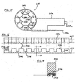
- FIGS. 15, 16, 17, and 18 show a fifth gastric band embodiment 230 for restricting food intake through the stomach.
- FIG. 15 is a top view of fifth gastric band embodiment 230, comprising a band 250 forming an enclosure 240.
- Band 250 attaches to and is actuated by a band actuator 252 in the same fashion as for the third gastric band embodiment 126 shown in FIG. 9.
- a plurality of pillows 238 slidably attaches to the inside of band 250.
- Pillows 238 are made of a soft, compliant, biocompatible material such as silicone rubber.
- FIG. 16 is a top view and FIG. 17 is a side view of plurality of pillows 238, which includes a first end 234 and a second end 236.
- Pillows 238 are equally spaced apart by a span 248 and attached to or integrally molded onto a base 244.
- the shape of each of pillows 238 may vary, but in general, pillows 238 form a continuous perimeter (without gaps) around enclosure 240 when the surgeon positions band 250 around the stomach. As the surgeon adjusts band 250 to tighten around the stomach, pillows 238 deform and bulge primarily in a radial, inward direction.
- FIG. 18 is a cross sectional view of band 250 slidably retained in a channel 246 of pillows 238.
- FIGS. 19 is a top view of a sixth gastric band embodiment 260, comprising a band actuator 278 and a band 266 forming an enclosure 270 for restricting food intake through the stomach.
- Band 266 and band actuator 278 are similar in design and operation to band 250 and band actuator 252 of the fifth gastric band embodiment shown in FIG.15.
- a plurality of bags 268 attaches to the inside of band 266 to form the tissue interface.
- FIG. 20 shows a portion of band 266 in a straight configuration and including a first bag 272 and a second bag 274.
- Each of bags 268 is made of a thin-wall, tough plastic material such as polyethylene, or of a thick-wall, soft, elastomeric material such as silicone rubber.
- FIG 21 is an enlarged view of first bag 272, which contains a multiplicity of beads 276.
- Beads 276 are generally spherically shaped and have a smooth surface finish so that bags 268 may conform readily to the stomach tissue. The exact shape and surface finish of beads 276 may be selected to provide the desired deformability characteristics of bags 268 for interfacing bodily tissue. Beads 276 may vary in size, and have a diameter not limited to, but approximately in the range, of 0.5 to 2.0 mm. Beads 276 may be made of a hard, biocompatible metal, ceramic, or plastic.
- bags 268 may be made of a water permeable material and filled with a hydrogel composition such as 98-99% hydrolyzed, polyvinyl alcohol (PVA).
- a hydrogel composition such as 98-99% hydrolyzed, polyvinyl alcohol (PVA).
- PVA polyvinyl alcohol
- Initially bags 268 would be flat and relatively flaccid to facilitate introduction into the body and placement around the stomach. Because of the osmotic pressure difference between body tissue fluid surrounding bags 268 and the hydrogel composition, fluids would pass into bags 268 and become absorbed by the hydrogel composition until equilibrium was reached. Consequently, the hydrogel composition would swell to many times the original, dehydrated volume, thus causing bags 268 to fill and provide soft and compliant tissue interfaces.
- the size of each bag at osmotic equilibrium may be predetermined depending on the exact mass and composition of the hydrogel material inside of each of bags 268.
- FIG. 22 and FIG. 23 show a seventh gastric band embodiment 290, comprising a band actuator 304 and a band 292 forming an enclosure 300 for restricting food intake through the stomach.
- Band 292 and band actuator 304 are similar in design and operation to band 250 and band actuator 252 of the sixth gastric band embodiment shown in FIG. 15.
- a tubular mesh 294 covers band 250 and has a first end 296 and a second end 298 attached to band 250.
- a plurality of sliding attachments 302 retains tubular mesh 294 against the outside of band 250.
- Tubular mesh 294 comprises a plurality of biocompatible, braided monofilaments made of an extruded plastic such as polyester or polyethylene. Similar products are available in the electrical industry for bundling wire cables and the like.
- Tubular mesh 294 is constructed so that when compression force is applied to the opposite ends in the longitudinal direction, and tubular mesh 294 is constrained from buckling, tubular mesh 294 shortens in length and grows in cross-sectional area.
- FIG. 22 is a top view of seventh gastric band embodiment 290 in a loose configuration;
- FIG. 23 is a top view in a tightened configuration, showing how actuating band 292 causes enclosure 300 to decrease in area as tubular mesh 294 bulges radially inward.
- Tubular mesh 294 optionally may be covered with a soft, compliant, elastic material such silicone to reduce trauma to the stomach tissue.
- tubular mesh 294 may also be filled with a fluid, beads or a hydrogel composition, as described for the embodiment shown in FIG. 21, in order to obtain desired tissue interface characteristics.
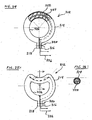
- FIG. 24 is a top view of a eighth gastric band embodiment 312, comprising a band 314 forming an enclosure 326 for restricting food intake through the stomach.
- Band 314 includes a filler 324, which may be made of a soft, biocompatible, elastic material such as silicone.
- Band 314 includes a first end 316 and a second end 318 held together with a suture 320 after placement around the stomach, so that enclosure 326 is approximately circular and loosely surrounding the stomach.
- clamp element 322 is in a first configuration having a radius of curvature approximately equal to the centerline radius of band 314.
- a surgeon may use control system 400 (FIG. 27) to electrically actuate clamp element 322 to change to a second configuration as shown in FIG.
- FIG. 26 is a cross-sectional view of band 314 containing clamping element 322. Clamping element 322 may be actuated again to resume the first configuration as shown in FIG. 25.
- clamping element 322 Although only one clamping element 322 is shown in FIG. 25, it is possible to have more than one clamping element, each independently actuatable via control system 400 so that the size of enclosure 326 may be reduced or increased in small, predetermined increments.
- Clamping element 322 comprises a pair of shape memory metal strips separated by a thin, flexible strip of insulating material such as PTFE, Teflon, or the like.
- the shape memory metal may be Nitinol that changes from a soft, pliable martinsitic structure to a hard, stiff austenitic structure at a temperature of approximately 60 degrees C.
- Two Nitinol strips are shape set into a curved configuration as shown in FIG. 24 while at a very high temperature. When the curved strips cool back to the martinsitic structure, the strip still maintains the shape set curvature, although each is again soft and pliable.
- one of the Nitinol strips is bent to the mirror-reflection curvature and then assembled to the other Nitinol strip with the insulation strip in between.
- a pair of electrical conductors is electrically connected to each strip so that they may be independently energized with electric current.
- that strip heats to a temperature slightly higher than the austenitic start temperature (60 degrees C, for example) and curves to the austenitic shape set configuration, if it was not already in that configuration.
- the force of one electrically actuated strip to bend to the austenitic shape set configuration is greater than the bending resistance of the non-actuated, soft, martinisitic strip. Therefore, when one strip is actuated and deforms into a new configuration, the non-actuated strip passively bends to the same configuration as the actuated strip.
- clamp elements each comprised of a pair of shape set Nitinol strips, may be constructed into band 314 and independently actuated by control system 400 (FIG. 27) to move radially inward or outward from the center of enclosure 326.
- the numerous clamp elements may be positioned end-to-end along the length of band 314.
- a surgeon may program control system 400 to only actuate a certain number of these clamp elements, in order to achieve a desired enclosure size and stomach restriction. If necessary, the enclosure may be further increased in size or decreased, depending on the needs of the patient, in a controllable fashion.
- bands are used for the treatment of fecal incontinence.
- One such band is described in U.S. Patent 6,461,292 which is hereby incorporated herein by reference.
- Bands can also be used to treat urinary incontinence.
- One such band is described in U.S. Patent Application 2003/0105385 which is hereby incorporated herein by reference.
- Bands can also be used to treat heartburn and/or acid reflux.
- One such band is described in U.S. Patent 6,470,892, which is hereby incorporated herein by reference.
- Bands can also be used to treat impotence.
- One such band is described in U.S. Patent Application 2003/0114729, which is hereby incorporated herein by reference.
Landscapes
- Health & Medical Sciences (AREA)
- Life Sciences & Earth Sciences (AREA)
- General Health & Medical Sciences (AREA)
- Public Health (AREA)
- Animal Behavior & Ethology (AREA)
- Vascular Medicine (AREA)
- Engineering & Computer Science (AREA)
- Biomedical Technology (AREA)
- Heart & Thoracic Surgery (AREA)
- Veterinary Medicine (AREA)
- Orthopedic Medicine & Surgery (AREA)
- Child & Adolescent Psychology (AREA)
- Nursing (AREA)
- Obesity (AREA)
- Surgery (AREA)
- Medical Informatics (AREA)
- Molecular Biology (AREA)
- Nuclear Medicine, Radiotherapy & Molecular Imaging (AREA)
- Reproductive Health (AREA)
- Surgical Instruments (AREA)
- Prostheses (AREA)
- Finger-Pressure Massage (AREA)
- Adornments (AREA)
- Massaging Devices (AREA)
- Medicines Containing Plant Substances (AREA)
Abstract
Description
Claims (8)
- A food intake restriction device for surgical application in the abdomen of a patient for forming a stoma opening in the stomach or esophagus of the patient, said device comprising:wherein said band contains a pair of substantially coextensive strands, said pair of strands having a first, non-rotatable end and a second, rotatable end whereby an operator may rotate said strands to twist them together in a first direction to decrease the size of said enclosure and in a second direction to increase the size of said enclosure.an elongated restriction member;forming means for forming said restriction member into at least a substantially closed loop around the stomach or the esophagus, said loop defining an enclosure;a control system for post-operative, non-invasive, mechanical adjustment of said restriction member to change the size of said enclosure;
- A food intake restriction device for surgical application in the abdomen of a patient for forming a stoma opening in the stomach or esophagus of the patient, the device comprising:an elongated, non-inflatable restriction member;forming means for forming said restriction member into at least a substantially closed loop around the stomach or the esophagus, said loop defining an enclosure;a control system for post-operative, non-invasive, mechanical adjustment of said restriction member to change the size of said enclosure; anda release mechanism for post-operative, non-invasive disengagement of said forming means from said restriction member.
- A food intake restriction device for surgical application in the abdomen of a patient for forming a stoma opening in the stomach or esophagus of the patient, the device comprising:a first, elongated restriction member, which is non-inflatable;a second, elongated restriction member, which is inflatable;forming means for forming said first and second restriction members into at least a substantially closed loop around the stomach or the esophagus, said loop defining an enclosure;a control system for post-operative, non-invasive, mechanical adjustment of said first restriction member to change the size of said enclosure; andan injection port fluidly connected to said second restriction member, whereby an operator may use a hypodermic needle to transcutaneously inject a fluid into said injection port to inflate said secondary restriction member to increase the restriction of food intake, or may use the hypodermic needle to transcutaneously withdraw the fluid via said injection port to deflate said secondary restriction member to decrease the restriction of food intake.
- A food intake restriction device for surgical application in the abdomen of a patient for forming a stoma opening in the stomach or esophagus of the patient, the device comprising:an elongated restriction member, said restriction member comprising a band made of a biocompatible material, said band containing an extendable member and a contractable member, said extendable and contractable members made of an electrically actuable, shape memory material;forming means for forming said restriction member into at least a substantially closed loop around the stomach or the esophagus, said loop defining an enclosure;a control system electrically connected to said extendable and contractable members, said control system for post-operative, non-invasive, mechanical adjustment of said restriction member to change the size of said enclosure.
- A food intake restriction device for surgical application in the abdomen of a patient for forming a stoma opening in the stomach or esophagus of the patient, the device comprising:an elongated, non-inflatable restriction member comprising a band that retains a plurality of pillows made of a soft, compliant, biocompatible material;forming means for forming said restriction member into at least a substantially closed loop around the stomach or the esophagus, said loop defining an enclosure;a control system for post-operative, non-invasive, mechanical adjustment of said restriction member to change the size of said enclosure.
- A food intake restriction device for surgical application in the abdomen of a patient for forming a stoma opening in the stomach or esophagus of the patient, the device comprising:an elongated, non-inflatable restriction member comprising a band that retains a plurality of bags, each of said bags containing a multiplicity of beads;forming means for forming said restriction member into at least a substantially closed loop around the stomach or the esophagus, said loop defining an enclosure;a control system for post-operative, non-invasive, mechanical adjustment of said restriction member to change the size of said enclosure.
- A food intake restriction device for surgical application in the abdomen of a patient for forming a stoma opening in the stomach or esophagus of the patient, the device comprising:an elongated, non-inflatable restriction member comprising a band covered by a tubular mesh made of a radially expandable, resilient, biocompatible material;forming means for forming said restriction member into at least a substantially closed loop around the stomach or the esophagus, said loop defining an enclosure;a control system for post-operative, non-invasive, mechanical adjustment of said restriction member to change the size of said enclosure, whereby when as said enclosure decreases in size, said tubular mesh radially expands.
- A food intake restriction device for surgical application in the abdomen of a patient for forming a stoma opening in the stomach or esophagus of the patient, the device comprising:an elongated restriction member comprising a band made of a biocompatible material, said band containing a clamp element having a first configuration with a first curvature and a second configuration with a second curvature that is a mirror image of said first curvature, said clamp element incrementally adjustable between said first and second configurations by the application of electrical current;forming means for forming said restriction member into at least a substantially closed loop around the stomach or the esophagus, said loop defining an enclosure;a control system for post-operative, non-invasive, mechanical adjustment of said restriction member to change the size of said enclosure, whereby an operator may controllably actuate said clamp element to change incrementally between said first configuration and said second configuration.
Applications Claiming Priority (2)
| Application Number | Priority Date | Filing Date | Title |
|---|---|---|---|
| US53049703P | 2003-12-17 | 2003-12-17 | |
| US530497P | 2003-12-17 |
Publications (3)
| Publication Number | Publication Date |
|---|---|
| EP1547549A2 true EP1547549A2 (en) | 2005-06-29 |
| EP1547549A3 EP1547549A3 (en) | 2005-08-31 |
| EP1547549B1 EP1547549B1 (en) | 2009-08-26 |
Family
ID=34549611
Family Applications (1)
| Application Number | Title | Priority Date | Filing Date |
|---|---|---|---|
| EP04257892A Expired - Lifetime EP1547549B1 (en) | 2003-12-17 | 2004-12-17 | Mechanically adjustable gastric band |
Country Status (9)
| Country | Link |
|---|---|
| EP (1) | EP1547549B1 (en) |
| JP (1) | JP4738806B2 (en) |
| CN (1) | CN100560036C (en) |
| AT (1) | ATE440576T1 (en) |
| AU (1) | AU2004235622A1 (en) |
| BR (1) | BRPI0405620B1 (en) |
| CA (1) | CA2490164C (en) |
| DE (1) | DE602004022767D1 (en) |
| DK (1) | DK1547549T3 (en) |
Cited By (50)
| Publication number | Priority date | Publication date | Assignee | Title |
|---|---|---|---|---|
| EP1747770A1 (en) * | 2005-07-28 | 2007-01-31 | Ethicon Endo-Surgery, Inc. | Electroactive polymer actuated gastric band |
| EP1779821A1 (en) * | 2005-10-26 | 2007-05-02 | Etervind AB | Adjustable gastric band |
| EP1834611A3 (en) * | 2006-03-13 | 2008-06-04 | Tyco Healthcare Group Lp | Transdermal magnetic coupling gastric banding |
| EP1967169A2 (en) | 2007-03-08 | 2008-09-10 | Ethicon Endo-Surgery, Inc. | Feedback sensing for a mechanical restrictive device |
| EP2074970A1 (en) * | 2007-12-27 | 2009-07-01 | Ethicon Endo-Surgery, Inc. | Constant force mechanisms for regulating restriction devices |
| US7601162B2 (en) | 2005-01-14 | 2009-10-13 | Ethicon Endo-Surgery, Inc. | Actuator for an implantable band |
| US7798954B2 (en) | 2006-01-04 | 2010-09-21 | Allergan, Inc. | Hydraulic gastric band with collapsible reservoir |
| US7862502B2 (en) | 2006-10-20 | 2011-01-04 | Ellipse Technologies, Inc. | Method and apparatus for adjusting a gastrointestinal restriction device |
| WO2011031619A1 (en) * | 2009-09-11 | 2011-03-17 | Ethicon Endo-Surgery, Inc. | Detachable antenna for remote band |
| WO2011035023A3 (en) * | 2009-09-18 | 2011-07-28 | Ethicon Endo-Surgery, Inc. | Tissue interface for implantable restriction system |
| US8043206B2 (en) | 2006-01-04 | 2011-10-25 | Allergan, Inc. | Self-regulating gastric band with pressure data processing |
| US20110270018A1 (en) * | 2010-04-29 | 2011-11-03 | Allergan, Inc. | Self-adjusting mechanical gastric band |
| WO2012064833A1 (en) * | 2010-11-12 | 2012-05-18 | Ethicon Endo-Surgery, Inc. | Gastric band with asymmetrical member |
| US8246533B2 (en) | 2006-10-20 | 2012-08-21 | Ellipse Technologies, Inc. | Implant system with resonant-driven actuator |
| US8376929B2 (en) | 2008-07-14 | 2013-02-19 | Allergan, Inc. | Implantable pump system with calibration |
| US8900118B2 (en) | 2008-10-22 | 2014-12-02 | Apollo Endosurgery, Inc. | Dome and screw valves for remotely adjustable gastric banding systems |
| US9050165B2 (en) | 2010-09-07 | 2015-06-09 | Apollo Endosurgery, Inc. | Remotely adjustable gastric banding system |
| WO2015117664A1 (en) | 2014-02-07 | 2015-08-13 | Myopowers Medical Technologies Sa | Medical device comprising an artificial contractile structure |
| US9192501B2 (en) | 2010-04-30 | 2015-11-24 | Apollo Endosurgery, Inc. | Remotely powered remotely adjustable gastric band system |
| US9295573B2 (en) | 2010-04-29 | 2016-03-29 | Apollo Endosurgery, Inc. | Self-adjusting gastric band having various compliant components and/or a satiety booster |
| WO2019043516A1 (en) * | 2017-09-01 | 2019-03-07 | Ethicon, Inc. | Adjustable implant |
| US10238427B2 (en) | 2015-02-19 | 2019-03-26 | Nuvasive Specialized Orthopedics, Inc. | Systems and methods for vertebral adjustment |
| US10271885B2 (en) | 2014-12-26 | 2019-04-30 | Nuvasive Specialized Orthopedics, Inc. | Systems and methods for distraction |
| WO2019106403A1 (en) | 2017-11-30 | 2019-06-06 | MyoPowers Medical Technologies France SAS | Artificial contractile structure and medical device comprising such |
| US10349995B2 (en) | 2007-10-30 | 2019-07-16 | Nuvasive Specialized Orthopedics, Inc. | Skeletal manipulation method |
| US10349982B2 (en) | 2011-11-01 | 2019-07-16 | Nuvasive Specialized Orthopedics, Inc. | Adjustable magnetic devices and methods of using same |
| US10405891B2 (en) | 2010-08-09 | 2019-09-10 | Nuvasive Specialized Orthopedics, Inc. | Maintenance feature in magnetic implant |
| US10517643B2 (en) | 2009-02-23 | 2019-12-31 | Nuvasive Specialized Orthopedics, Inc. | Non-invasive adjustable distraction system |
| US10646262B2 (en) | 2011-02-14 | 2020-05-12 | Nuvasive Specialized Orthopedics, Inc. | System and method for altering rotational alignment of bone sections |
| US10653517B2 (en) | 2017-11-08 | 2020-05-19 | Mentor Worldwide Llc | Adjustable implant |
| US10660675B2 (en) | 2010-06-30 | 2020-05-26 | Nuvasive Specialized Orthopedics, Inc. | External adjustment device for distraction device |
| US10729470B2 (en) | 2008-11-10 | 2020-08-04 | Nuvasive Specialized Orthopedics, Inc. | External adjustment device for distraction device |
| US10743794B2 (en) | 2011-10-04 | 2020-08-18 | Nuvasive Specialized Orthopedics, Inc. | Devices and methods for non-invasive implant length sensing |
| US10751094B2 (en) | 2013-10-10 | 2020-08-25 | Nuvasive Specialized Orthopedics, Inc. | Adjustable spinal implant |
| US10751163B2 (en) | 2017-09-01 | 2020-08-25 | Mentor Worldwide Llc | Adjustable implant |
| US10751165B2 (en) | 2017-12-12 | 2020-08-25 | Mentor Worldwide Llc | Adjustable implant |
| US10835290B2 (en) | 2015-12-10 | 2020-11-17 | Nuvasive Specialized Orthopedics, Inc. | External adjustment device for distraction device |
| US10842496B2 (en) | 2018-12-17 | 2020-11-24 | Ethicon Llc | Implantable sphincter assistance device with tuned magnetic features |
| US10918425B2 (en) | 2016-01-28 | 2021-02-16 | Nuvasive Specialized Orthopedics, Inc. | System and methods for bone transport |
| US11051931B2 (en) | 2018-10-31 | 2021-07-06 | Cilag Gmbh International | Active sphincter implant to re-route flow through gastrointestinal tract |
| US11071619B2 (en) | 2018-12-17 | 2021-07-27 | Cilag Gmbh International | Coupling assembly for implantable sphincter assistance device |
| US11191579B2 (en) | 2012-10-29 | 2021-12-07 | Nuvasive Specialized Orthopedics, Inc. | Adjustable devices for treating arthritis of the knee |
| US11234808B2 (en) | 2016-02-29 | 2022-02-01 | Biosense Webster (Israel) Ltd. | Pressure changer for a breast implant |
| US11246694B2 (en) | 2014-04-28 | 2022-02-15 | Nuvasive Specialized Orthopedics, Inc. | System for informational magnetic feedback in adjustable implants |
| US11298136B2 (en) | 2018-12-19 | 2022-04-12 | Cilag Gmbh International | Implantable sphincter assistance device with deformable elements |
| US11376146B2 (en) | 2018-12-17 | 2022-07-05 | Cilag Gmbh International | Tissue interface features for implantable sphincter assistance device |
| US11399928B2 (en) | 2018-12-19 | 2022-08-02 | Cilag Gmbh International | Linking elements for implantable sphincter assistance device |
| US11478347B2 (en) | 2018-12-17 | 2022-10-25 | Cilag Gmbh International | Sphincter sizing instrument |
| US12151071B2 (en) | 2019-09-09 | 2024-11-26 | Shifamed Holdings, Llc | Adjustable shunts and associated systems and methods |
| US12491347B2 (en) | 2020-08-25 | 2025-12-09 | Shifamed Holdings, Llc | Adjustable interatrial shunts and associated systems and methods |
Families Citing this family (51)
| Publication number | Priority date | Publication date | Assignee | Title |
|---|---|---|---|---|
| US7338433B2 (en) | 2002-08-13 | 2008-03-04 | Allergan, Inc. | Remotely adjustable gastric banding method |
| BR0306183A (en) | 2002-08-28 | 2004-10-19 | Inamed Medical Products Corp | Fatigue Resistant Gastric Banding Device |
| AU2005208721B2 (en) * | 2004-01-23 | 2010-09-23 | Boston Scientific Scimed, Inc. | Releasably-securable one-piece adjustable gastric band |
| DK1725193T3 (en) | 2004-03-08 | 2009-11-30 | Allergan Medical S A | Closing system for tubular members |
| ATE517652T1 (en) | 2004-03-18 | 2011-08-15 | Allergan Inc | DEVICE FOR ADJUSTING THE VOLUME OF INTRAGASTRAL BALLOONS |
| US7946976B2 (en) | 2004-03-23 | 2011-05-24 | Michael Gertner | Methods and devices for the surgical creation of satiety and biofeedback pathways |
| WO2006049725A2 (en) | 2004-03-23 | 2006-05-11 | Minimus Surgical Systems | Surgical systems and devices to enhance gastric restriction therapies |
| US7255675B2 (en) | 2004-03-23 | 2007-08-14 | Michael Gertner | Devices and methods to treat a patient |
| US7775966B2 (en) | 2005-02-24 | 2010-08-17 | Ethicon Endo-Surgery, Inc. | Non-invasive pressure measurement in a fluid adjustable restrictive device |
| US7927270B2 (en) | 2005-02-24 | 2011-04-19 | Ethicon Endo-Surgery, Inc. | External mechanical pressure sensor for gastric band pressure measurements |
| US7775215B2 (en) | 2005-02-24 | 2010-08-17 | Ethicon Endo-Surgery, Inc. | System and method for determining implanted device positioning and obtaining pressure data |
| US8066629B2 (en) | 2005-02-24 | 2011-11-29 | Ethicon Endo-Surgery, Inc. | Apparatus for adjustment and sensing of gastric band pressure |
| US7699770B2 (en) | 2005-02-24 | 2010-04-20 | Ethicon Endo-Surgery, Inc. | Device for non-invasive measurement of fluid pressure in an adjustable restriction device |
| US7658196B2 (en) | 2005-02-24 | 2010-02-09 | Ethicon Endo-Surgery, Inc. | System and method for determining implanted device orientation |
| US8016744B2 (en) | 2005-02-24 | 2011-09-13 | Ethicon Endo-Surgery, Inc. | External pressure-based gastric band adjustment system and method |
| US8251888B2 (en) | 2005-04-13 | 2012-08-28 | Mitchell Steven Roslin | Artificial gastric valve |
| US8870742B2 (en) | 2006-04-06 | 2014-10-28 | Ethicon Endo-Surgery, Inc. | GUI for an implantable restriction device and a data logger |
| US8152710B2 (en) | 2006-04-06 | 2012-04-10 | Ethicon Endo-Surgery, Inc. | Physiological parameter analysis for an implantable restriction device and a data logger |
| US8187163B2 (en) | 2007-12-10 | 2012-05-29 | Ethicon Endo-Surgery, Inc. | Methods for implanting a gastric restriction device |
| US8100870B2 (en) | 2007-12-14 | 2012-01-24 | Ethicon Endo-Surgery, Inc. | Adjustable height gastric restriction devices and methods |
| US8142452B2 (en) | 2007-12-27 | 2012-03-27 | Ethicon Endo-Surgery, Inc. | Controlling pressure in adjustable restriction devices |
| US8337389B2 (en) | 2008-01-28 | 2012-12-25 | Ethicon Endo-Surgery, Inc. | Methods and devices for diagnosing performance of a gastric restriction system |
| US8192350B2 (en) | 2008-01-28 | 2012-06-05 | Ethicon Endo-Surgery, Inc. | Methods and devices for measuring impedance in a gastric restriction system |
| US8591395B2 (en) | 2008-01-28 | 2013-11-26 | Ethicon Endo-Surgery, Inc. | Gastric restriction device data handling devices and methods |
| EP2240138B1 (en) * | 2008-01-29 | 2021-07-21 | Implantica Patent Ltd. | Apparatus for treating obesity |
| US7844342B2 (en) | 2008-02-07 | 2010-11-30 | Ethicon Endo-Surgery, Inc. | Powering implantable restriction systems using light |
| US8221439B2 (en) | 2008-02-07 | 2012-07-17 | Ethicon Endo-Surgery, Inc. | Powering implantable restriction systems using kinetic motion |
| US8114345B2 (en) | 2008-02-08 | 2012-02-14 | Ethicon Endo-Surgery, Inc. | System and method of sterilizing an implantable medical device |
| US8057492B2 (en) | 2008-02-12 | 2011-11-15 | Ethicon Endo-Surgery, Inc. | Automatically adjusting band system with MEMS pump |
| US8591532B2 (en) | 2008-02-12 | 2013-11-26 | Ethicon Endo-Sugery, Inc. | Automatically adjusting band system |
| US8034065B2 (en) | 2008-02-26 | 2011-10-11 | Ethicon Endo-Surgery, Inc. | Controlling pressure in adjustable restriction devices |
| US8233995B2 (en) | 2008-03-06 | 2012-07-31 | Ethicon Endo-Surgery, Inc. | System and method of aligning an implantable antenna |
| US8187162B2 (en) | 2008-03-06 | 2012-05-29 | Ethicon Endo-Surgery, Inc. | Reorientation port |
| US8292800B2 (en) | 2008-06-11 | 2012-10-23 | Allergan, Inc. | Implantable pump system |
| US8317677B2 (en) | 2008-10-06 | 2012-11-27 | Allergan, Inc. | Mechanical gastric band with cushions |
| US8678993B2 (en) | 2010-02-12 | 2014-03-25 | Apollo Endosurgery, Inc. | Remotely adjustable gastric banding system |
| US8758221B2 (en) | 2010-02-24 | 2014-06-24 | Apollo Endosurgery, Inc. | Source reservoir with potential energy for remotely adjustable gastric banding system |
| US8764624B2 (en) | 2010-02-25 | 2014-07-01 | Apollo Endosurgery, Inc. | Inductively powered remotely adjustable gastric banding system |
| US8840541B2 (en) | 2010-02-25 | 2014-09-23 | Apollo Endosurgery, Inc. | Pressure sensing gastric banding system |
| US8939888B2 (en) | 2010-04-28 | 2015-01-27 | Apollo Endosurgery, Inc. | Method and system for determining the pressure of a fluid in a syringe, an access port, a catheter, and a gastric band |
| US9044298B2 (en) | 2010-04-29 | 2015-06-02 | Apollo Endosurgery, Inc. | Self-adjusting gastric band |
| US9226840B2 (en) | 2010-06-03 | 2016-01-05 | Apollo Endosurgery, Inc. | Magnetically coupled implantable pump system and method |
| US8517915B2 (en) | 2010-06-10 | 2013-08-27 | Allergan, Inc. | Remotely adjustable gastric banding system |
| US9211207B2 (en) | 2010-08-18 | 2015-12-15 | Apollo Endosurgery, Inc. | Power regulated implant |
| US8698373B2 (en) | 2010-08-18 | 2014-04-15 | Apollo Endosurgery, Inc. | Pare piezo power with energy recovery |
| US8961393B2 (en) | 2010-11-15 | 2015-02-24 | Apollo Endosurgery, Inc. | Gastric band devices and drive systems |
| US8725435B2 (en) | 2011-04-13 | 2014-05-13 | Apollo Endosurgery, Inc. | Syringe-based leak detection system |
| US8876694B2 (en) | 2011-12-07 | 2014-11-04 | Apollo Endosurgery, Inc. | Tube connector with a guiding tip |
| US8961394B2 (en) | 2011-12-20 | 2015-02-24 | Apollo Endosurgery, Inc. | Self-sealing fluid joint for use with a gastric band |
| JP6958793B2 (en) * | 2018-04-25 | 2021-11-02 | マイオパワーズ メディカル テクノロジーズ フランス エスエーエスMyoPowers Medical Technologies France SAS | Medical device with artificial contraction structure |
| JP6958792B2 (en) * | 2018-04-25 | 2021-11-02 | マイオパワーズ メディカル テクノロジーズ フランス エスエーエスMyoPowers Medical Technologies France SAS | Medical device with artificial contraction structure |
Family Cites Families (8)
| Publication number | Priority date | Publication date | Assignee | Title |
|---|---|---|---|---|
| US4592339A (en) * | 1985-06-12 | 1986-06-03 | Mentor Corporation | Gastric banding device |
| US5938669A (en) * | 1997-05-07 | 1999-08-17 | Klasamed S.A. | Adjustable gastric banding device for contracting a patient's stomach |
| US6067991A (en) * | 1998-08-13 | 2000-05-30 | Forsell; Peter | Mechanical food intake restriction device |
| US6460543B1 (en) * | 1998-08-13 | 2002-10-08 | Obtech Medical Ag | Non-injection port food intake restriction device |
| FR2783153B1 (en) * | 1998-09-14 | 2000-12-01 | Jerome Dargent | GASTRIC CONSTRICTION DEVICE |
| FR2797181B1 (en) * | 1999-08-05 | 2002-05-03 | Richard Cancel | REMOTE GASTRIC BAND DEVICE FOR FORMING A RESTRICTED STOMA OPENING IN THE ESTOMAC |
| US6461292B1 (en) * | 1999-08-12 | 2002-10-08 | Obtech Medical Ag | Anal incontinence treatment with wireless energy supply |
| CN1250168C (en) * | 1999-08-12 | 2006-04-12 | 波滕西亚医疗公司 | A device that creates a stoma in a patient's stomach or esophagus |
-
2004
- 2004-12-02 AU AU2004235622A patent/AU2004235622A1/en not_active Abandoned
- 2004-12-13 CA CA2490164A patent/CA2490164C/en not_active Expired - Fee Related
- 2004-12-16 JP JP2004364883A patent/JP4738806B2/en not_active Expired - Fee Related
- 2004-12-17 DE DE602004022767T patent/DE602004022767D1/en not_active Expired - Lifetime
- 2004-12-17 CN CNB2004100818261A patent/CN100560036C/en not_active Expired - Fee Related
- 2004-12-17 BR BRPI0405620-5A patent/BRPI0405620B1/en not_active IP Right Cessation
- 2004-12-17 DK DK04257892T patent/DK1547549T3/en active
- 2004-12-17 AT AT04257892T patent/ATE440576T1/en not_active IP Right Cessation
- 2004-12-17 EP EP04257892A patent/EP1547549B1/en not_active Expired - Lifetime
Cited By (74)
| Publication number | Priority date | Publication date | Assignee | Title |
|---|---|---|---|---|
| US7879068B2 (en) | 2005-01-14 | 2011-02-01 | Ethicon Endo-Surgery, Inc. | Feedback sensing for a mechanical restrictive device |
| US7601162B2 (en) | 2005-01-14 | 2009-10-13 | Ethicon Endo-Surgery, Inc. | Actuator for an implantable band |
| EP1747770A1 (en) * | 2005-07-28 | 2007-01-31 | Ethicon Endo-Surgery, Inc. | Electroactive polymer actuated gastric band |
| US7766815B2 (en) | 2005-07-28 | 2010-08-03 | Ethicon Endo-Surgery, Inc. | Electroactive polymer actuated gastric band |
| EP1779821A1 (en) * | 2005-10-26 | 2007-05-02 | Etervind AB | Adjustable gastric band |
| WO2007048822A1 (en) * | 2005-10-26 | 2007-05-03 | Etervind Ab | Adustable gastric band |
| US8043206B2 (en) | 2006-01-04 | 2011-10-25 | Allergan, Inc. | Self-regulating gastric band with pressure data processing |
| US7798954B2 (en) | 2006-01-04 | 2010-09-21 | Allergan, Inc. | Hydraulic gastric band with collapsible reservoir |
| EP1834611A3 (en) * | 2006-03-13 | 2008-06-04 | Tyco Healthcare Group Lp | Transdermal magnetic coupling gastric banding |
| US8715159B2 (en) | 2006-10-20 | 2014-05-06 | Ellipse Technologies, Inc. | Adjustable implant and method of use |
| US10039661B2 (en) | 2006-10-20 | 2018-08-07 | Nuvasive Specialized Orthopedics, Inc. | Adjustable implant and method of use |
| US11234849B2 (en) | 2006-10-20 | 2022-02-01 | Nuvasive Specialized Orthopedics, Inc. | Adjustable implant and method of use |
| US7981025B2 (en) | 2006-10-20 | 2011-07-19 | Ellipse Technologies, Inc. | Adjustable implant and method of use |
| US7862502B2 (en) | 2006-10-20 | 2011-01-04 | Ellipse Technologies, Inc. | Method and apparatus for adjusting a gastrointestinal restriction device |
| US9526650B2 (en) | 2006-10-20 | 2016-12-27 | Nuvasive Specialized Orthopedics, Inc. | Adjustable implant and method of use |
| US9271857B2 (en) | 2006-10-20 | 2016-03-01 | Ellipse Technologies, Inc. | Adjustable implant and method of use |
| US11672684B2 (en) | 2006-10-20 | 2023-06-13 | Nuvasive Specialized Orthopedics, Inc. | Adjustable implant and method of use |
| US8246533B2 (en) | 2006-10-20 | 2012-08-21 | Ellipse Technologies, Inc. | Implant system with resonant-driven actuator |
| US8808163B2 (en) | 2006-10-20 | 2014-08-19 | Ellipse Technologies, Inc. | Adjustable implant and method of use |
| EP1967169A2 (en) | 2007-03-08 | 2008-09-10 | Ethicon Endo-Surgery, Inc. | Feedback sensing for a mechanical restrictive device |
| US10349995B2 (en) | 2007-10-30 | 2019-07-16 | Nuvasive Specialized Orthopedics, Inc. | Skeletal manipulation method |
| US11172972B2 (en) | 2007-10-30 | 2021-11-16 | Nuvasive Specialized Orthopedics, Inc. | Skeletal manipulation method |
| EP2074970A1 (en) * | 2007-12-27 | 2009-07-01 | Ethicon Endo-Surgery, Inc. | Constant force mechanisms for regulating restriction devices |
| US8376929B2 (en) | 2008-07-14 | 2013-02-19 | Allergan, Inc. | Implantable pump system with calibration |
| US8900118B2 (en) | 2008-10-22 | 2014-12-02 | Apollo Endosurgery, Inc. | Dome and screw valves for remotely adjustable gastric banding systems |
| US10729470B2 (en) | 2008-11-10 | 2020-08-04 | Nuvasive Specialized Orthopedics, Inc. | External adjustment device for distraction device |
| US10517643B2 (en) | 2009-02-23 | 2019-12-31 | Nuvasive Specialized Orthopedics, Inc. | Non-invasive adjustable distraction system |
| AU2010292457B2 (en) * | 2009-09-11 | 2015-04-02 | Ethicon Endo-Surgery, Inc. | Detachable antenna for remote band |
| WO2011031619A1 (en) * | 2009-09-11 | 2011-03-17 | Ethicon Endo-Surgery, Inc. | Detachable antenna for remote band |
| WO2011035023A3 (en) * | 2009-09-18 | 2011-07-28 | Ethicon Endo-Surgery, Inc. | Tissue interface for implantable restriction system |
| US9295573B2 (en) | 2010-04-29 | 2016-03-29 | Apollo Endosurgery, Inc. | Self-adjusting gastric band having various compliant components and/or a satiety booster |
| US20110270018A1 (en) * | 2010-04-29 | 2011-11-03 | Allergan, Inc. | Self-adjusting mechanical gastric band |
| US9028394B2 (en) * | 2010-04-29 | 2015-05-12 | Apollo Endosurgery, Inc. | Self-adjusting mechanical gastric band |
| US9192501B2 (en) | 2010-04-30 | 2015-11-24 | Apollo Endosurgery, Inc. | Remotely powered remotely adjustable gastric band system |
| US10660675B2 (en) | 2010-06-30 | 2020-05-26 | Nuvasive Specialized Orthopedics, Inc. | External adjustment device for distraction device |
| US10405891B2 (en) | 2010-08-09 | 2019-09-10 | Nuvasive Specialized Orthopedics, Inc. | Maintenance feature in magnetic implant |
| US9050165B2 (en) | 2010-09-07 | 2015-06-09 | Apollo Endosurgery, Inc. | Remotely adjustable gastric banding system |
| US8632455B2 (en) | 2010-11-12 | 2014-01-21 | Ethicon Endo-Surgery, Inc. | Gastric band with asymmetrical member |
| WO2012064833A1 (en) * | 2010-11-12 | 2012-05-18 | Ethicon Endo-Surgery, Inc. | Gastric band with asymmetrical member |
| US10646262B2 (en) | 2011-02-14 | 2020-05-12 | Nuvasive Specialized Orthopedics, Inc. | System and method for altering rotational alignment of bone sections |
| US10743794B2 (en) | 2011-10-04 | 2020-08-18 | Nuvasive Specialized Orthopedics, Inc. | Devices and methods for non-invasive implant length sensing |
| US10349982B2 (en) | 2011-11-01 | 2019-07-16 | Nuvasive Specialized Orthopedics, Inc. | Adjustable magnetic devices and methods of using same |
| US11123107B2 (en) | 2011-11-01 | 2021-09-21 | Nuvasive Specialized Orthopedics, Inc. | Adjustable magnetic devices and methods of using same |
| US11213330B2 (en) | 2012-10-29 | 2022-01-04 | Nuvasive Specialized Orthopedics, Inc. | Adjustable devices for treating arthritis of the knee |
| US11191579B2 (en) | 2012-10-29 | 2021-12-07 | Nuvasive Specialized Orthopedics, Inc. | Adjustable devices for treating arthritis of the knee |
| US10751094B2 (en) | 2013-10-10 | 2020-08-25 | Nuvasive Specialized Orthopedics, Inc. | Adjustable spinal implant |
| WO2015117664A1 (en) | 2014-02-07 | 2015-08-13 | Myopowers Medical Technologies Sa | Medical device comprising an artificial contractile structure |
| US11246694B2 (en) | 2014-04-28 | 2022-02-15 | Nuvasive Specialized Orthopedics, Inc. | System for informational magnetic feedback in adjustable implants |
| US10271885B2 (en) | 2014-12-26 | 2019-04-30 | Nuvasive Specialized Orthopedics, Inc. | Systems and methods for distraction |
| US11439449B2 (en) | 2014-12-26 | 2022-09-13 | Nuvasive Specialized Orthopedics, Inc. | Systems and methods for distraction |
| US10238427B2 (en) | 2015-02-19 | 2019-03-26 | Nuvasive Specialized Orthopedics, Inc. | Systems and methods for vertebral adjustment |
| US12076051B2 (en) | 2015-02-19 | 2024-09-03 | Nuvasive Specialized Orthopedics, Inc. | Systems and methods for vertebral adjustment |
| US11612416B2 (en) | 2015-02-19 | 2023-03-28 | Nuvasive Specialized Orthopedics, Inc. | Systems and methods for vertebral adjustment |
| US10835290B2 (en) | 2015-12-10 | 2020-11-17 | Nuvasive Specialized Orthopedics, Inc. | External adjustment device for distraction device |
| US10918425B2 (en) | 2016-01-28 | 2021-02-16 | Nuvasive Specialized Orthopedics, Inc. | System and methods for bone transport |
| US11234808B2 (en) | 2016-02-29 | 2022-02-01 | Biosense Webster (Israel) Ltd. | Pressure changer for a breast implant |
| US11491005B2 (en) | 2017-09-01 | 2022-11-08 | Mentor Worldwide Llc | Adjustable implant |
| US10751163B2 (en) | 2017-09-01 | 2020-08-25 | Mentor Worldwide Llc | Adjustable implant |
| WO2019043516A1 (en) * | 2017-09-01 | 2019-03-07 | Ethicon, Inc. | Adjustable implant |
| US10653517B2 (en) | 2017-11-08 | 2020-05-19 | Mentor Worldwide Llc | Adjustable implant |
| WO2019106403A1 (en) | 2017-11-30 | 2019-06-06 | MyoPowers Medical Technologies France SAS | Artificial contractile structure and medical device comprising such |
| US10751165B2 (en) | 2017-12-12 | 2020-08-25 | Mentor Worldwide Llc | Adjustable implant |
| US11678972B2 (en) | 2017-12-12 | 2023-06-20 | Mentor Worldwide Llc | Adjustable implant |
| US11051931B2 (en) | 2018-10-31 | 2021-07-06 | Cilag Gmbh International | Active sphincter implant to re-route flow through gastrointestinal tract |
| US10842496B2 (en) | 2018-12-17 | 2020-11-24 | Ethicon Llc | Implantable sphincter assistance device with tuned magnetic features |
| US11071619B2 (en) | 2018-12-17 | 2021-07-27 | Cilag Gmbh International | Coupling assembly for implantable sphincter assistance device |
| US11478347B2 (en) | 2018-12-17 | 2022-10-25 | Cilag Gmbh International | Sphincter sizing instrument |
| US11376146B2 (en) | 2018-12-17 | 2022-07-05 | Cilag Gmbh International | Tissue interface features for implantable sphincter assistance device |
| US11298136B2 (en) | 2018-12-19 | 2022-04-12 | Cilag Gmbh International | Implantable sphincter assistance device with deformable elements |
| US11399928B2 (en) | 2018-12-19 | 2022-08-02 | Cilag Gmbh International | Linking elements for implantable sphincter assistance device |
| US12036108B2 (en) | 2018-12-19 | 2024-07-16 | Cilag Gmbh International | Linking elements for implantable sphincter assistance device |
| US12151071B2 (en) | 2019-09-09 | 2024-11-26 | Shifamed Holdings, Llc | Adjustable shunts and associated systems and methods |
| US12343487B2 (en) | 2019-09-09 | 2025-07-01 | Shifamed Holdings, Llc | Adjustable shunts and associated systems and methods |
| US12491347B2 (en) | 2020-08-25 | 2025-12-09 | Shifamed Holdings, Llc | Adjustable interatrial shunts and associated systems and methods |
Also Published As
| Publication number | Publication date |
|---|---|
| CA2490164C (en) | 2012-08-14 |
| EP1547549A3 (en) | 2005-08-31 |
| AU2004235622A1 (en) | 2005-07-07 |
| DK1547549T3 (en) | 2009-12-14 |
| BRPI0405620A (en) | 2005-08-23 |
| CA2490164A1 (en) | 2005-06-17 |
| EP1547549B1 (en) | 2009-08-26 |
| ATE440576T1 (en) | 2009-09-15 |
| DE602004022767D1 (en) | 2009-10-08 |
| JP2005177491A (en) | 2005-07-07 |
| CN100560036C (en) | 2009-11-18 |
| BRPI0405620B1 (en) | 2014-07-22 |
| JP4738806B2 (en) | 2011-08-03 |
| CN1736347A (en) | 2006-02-22 |
Similar Documents
| Publication | Publication Date | Title |
|---|---|---|
| EP1547549B1 (en) | Mechanically adjustable gastric band | |
| US20240050256A1 (en) | Device for treating obesity | |
| US7238191B2 (en) | Surgical ring featuring a reversible diameter remote control system | |
| JP5451113B2 (en) | Orientation reset port | |
| CN1765338B (en) | An improved fluid adjustable band | |
| JP5367397B2 (en) | Automatic adjustment band system | |
| EP2074970B1 (en) | Constant force mechanisms for regulating restriction devices | |
| US20090222031A1 (en) | Adjustable gastric band | |
| US20070265646A1 (en) | Dynamically adjustable gastric implants | |
| US20070185374A1 (en) | Two-way adjustable implant | |
| US20050192629A1 (en) | Methods and apparatus for creating and regulating a gastric stoma | |
| EP2095797B1 (en) | Devices for fixing antenna orientation in a restriction system | |
| EP2059176A2 (en) | An implantable coil for insertion into a hollow body organ | |
| US20100114125A1 (en) | Method of remotely adjusting a satiation and satiety-inducing implanted device | |
| US20080097510A1 (en) | Method for inducing weight loss with a patient | |
| AU2011204942B2 (en) | Mechanically adjustable gastric band | |
| US20100114148A1 (en) | Devices and methods for adjusting a satiation and satiety-inducing implanted device | |
| HK1137327B (en) | Devices for fixing antenna orientation in a restriction system | |
| MX2011007881A (en) | An apparatus for treating gerd. |
Legal Events
| Date | Code | Title | Description |
|---|---|---|---|
| PUAI | Public reference made under article 153(3) epc to a published international application that has entered the european phase |
Free format text: ORIGINAL CODE: 0009012 |
|
| AK | Designated contracting states |
Kind code of ref document: A2 Designated state(s): AT BE BG CH CY CZ DE DK EE ES FI FR GB GR HU IE IS IT LI LT LU MC NL PL PT RO SE SI SK TR |
|
| AX | Request for extension of the european patent |
Extension state: AL BA HR LV MK YU |
|
| RIN1 | Information on inventor provided before grant (corrected) |
Inventor name: CONLON, SEAN Inventor name: UTH, JOSH Inventor name: DLUGOS, DAN Inventor name: FREEMAN, LYNN Inventor name: HASSLER, BILL Inventor name: HUITEMA, TOM Inventor name: SCHULZE, DALE Inventor name: BYRUM, RANDY Inventor name: MCKENNA, ROB Inventor name: ORTIZ, MARK |
|
| PUAL | Search report despatched |
Free format text: ORIGINAL CODE: 0009013 |
|
| AK | Designated contracting states |
Kind code of ref document: A3 Designated state(s): AT BE BG CH CY CZ DE DK EE ES FI FR GB GR HU IE IS IT LI LT LU MC NL PL PT RO SE SI SK TR |
|
| AX | Request for extension of the european patent |
Extension state: AL BA HR LV MK YU |
|
| 17P | Request for examination filed |
Effective date: 20060208 |
|
| AKX | Designation fees paid |
Designated state(s): AT BE BG CH CY CZ DE DK EE ES FI FR GB GR HU IE IS IT LI LT LU MC NL PL PT RO SE SI SK TR |
|
| 17Q | First examination report despatched |
Effective date: 20070207 |
|
| GRAP | Despatch of communication of intention to grant a patent |
Free format text: ORIGINAL CODE: EPIDOSNIGR1 |
|
| GRAP | Despatch of communication of intention to grant a patent |
Free format text: ORIGINAL CODE: EPIDOSNIGR1 |
|
| GRAS | Grant fee paid |
Free format text: ORIGINAL CODE: EPIDOSNIGR3 |
|
| GRAA | (expected) grant |
Free format text: ORIGINAL CODE: 0009210 |
|
| AK | Designated contracting states |
Kind code of ref document: B1 Designated state(s): AT BE BG CH CY CZ DE DK EE ES FI FR GB GR HU IE IS IT LI LT LU MC NL PL PT RO SE SI SK TR |
|
| REG | Reference to a national code |
Ref country code: GB Ref legal event code: FG4D |
|
| REG | Reference to a national code |
Ref country code: CH Ref legal event code: EP |
|
| REG | Reference to a national code |
Ref country code: IE Ref legal event code: FG4D |
|
| REF | Corresponds to: |
Ref document number: 602004022767 Country of ref document: DE Date of ref document: 20091008 Kind code of ref document: P |
|
| REG | Reference to a national code |
Ref country code: DK Ref legal event code: T3 |
|
| LTIE | Lt: invalidation of european patent or patent extension |
Effective date: 20090826 |
|
| PG25 | Lapsed in a contracting state [announced via postgrant information from national office to epo] |
Ref country code: LT Free format text: LAPSE BECAUSE OF FAILURE TO SUBMIT A TRANSLATION OF THE DESCRIPTION OR TO PAY THE FEE WITHIN THE PRESCRIBED TIME-LIMIT Effective date: 20090826 Ref country code: AT Free format text: LAPSE BECAUSE OF FAILURE TO SUBMIT A TRANSLATION OF THE DESCRIPTION OR TO PAY THE FEE WITHIN THE PRESCRIBED TIME-LIMIT Effective date: 20090826 Ref country code: IS Free format text: LAPSE BECAUSE OF FAILURE TO SUBMIT A TRANSLATION OF THE DESCRIPTION OR TO PAY THE FEE WITHIN THE PRESCRIBED TIME-LIMIT Effective date: 20091226 Ref country code: FI Free format text: LAPSE BECAUSE OF FAILURE TO SUBMIT A TRANSLATION OF THE DESCRIPTION OR TO PAY THE FEE WITHIN THE PRESCRIBED TIME-LIMIT Effective date: 20090826 Ref country code: SE Free format text: LAPSE BECAUSE OF FAILURE TO SUBMIT A TRANSLATION OF THE DESCRIPTION OR TO PAY THE FEE WITHIN THE PRESCRIBED TIME-LIMIT Effective date: 20090826 |
|
| PGFP | Annual fee paid to national office [announced via postgrant information from national office to epo] |
Ref country code: CH Payment date: 20091215 Year of fee payment: 6 Ref country code: DK Payment date: 20091211 Year of fee payment: 6 Ref country code: IE Payment date: 20091215 Year of fee payment: 6 Ref country code: LU Payment date: 20091218 Year of fee payment: 6 Ref country code: MC Payment date: 20091127 Year of fee payment: 6 |
|
| NLV1 | Nl: lapsed or annulled due to failure to fulfill the requirements of art. 29p and 29m of the patents act | ||
| PG25 | Lapsed in a contracting state [announced via postgrant information from national office to epo] |
Ref country code: NL Free format text: LAPSE BECAUSE OF FAILURE TO SUBMIT A TRANSLATION OF THE DESCRIPTION OR TO PAY THE FEE WITHIN THE PRESCRIBED TIME-LIMIT Effective date: 20090826 Ref country code: PL Free format text: LAPSE BECAUSE OF FAILURE TO SUBMIT A TRANSLATION OF THE DESCRIPTION OR TO PAY THE FEE WITHIN THE PRESCRIBED TIME-LIMIT Effective date: 20090826 Ref country code: SI Free format text: LAPSE BECAUSE OF FAILURE TO SUBMIT A TRANSLATION OF THE DESCRIPTION OR TO PAY THE FEE WITHIN THE PRESCRIBED TIME-LIMIT Effective date: 20090826 |
|
| PG25 | Lapsed in a contracting state [announced via postgrant information from national office to epo] |
Ref country code: BG Free format text: LAPSE BECAUSE OF FAILURE TO SUBMIT A TRANSLATION OF THE DESCRIPTION OR TO PAY THE FEE WITHIN THE PRESCRIBED TIME-LIMIT Effective date: 20091126 Ref country code: CY Free format text: LAPSE BECAUSE OF FAILURE TO SUBMIT A TRANSLATION OF THE DESCRIPTION OR TO PAY THE FEE WITHIN THE PRESCRIBED TIME-LIMIT Effective date: 20090826 Ref country code: PT Free format text: LAPSE BECAUSE OF FAILURE TO SUBMIT A TRANSLATION OF THE DESCRIPTION OR TO PAY THE FEE WITHIN THE PRESCRIBED TIME-LIMIT Effective date: 20091228 |
|
| PG25 | Lapsed in a contracting state [announced via postgrant information from national office to epo] |
Ref country code: EE Free format text: LAPSE BECAUSE OF FAILURE TO SUBMIT A TRANSLATION OF THE DESCRIPTION OR TO PAY THE FEE WITHIN THE PRESCRIBED TIME-LIMIT Effective date: 20090826 Ref country code: ES Free format text: LAPSE BECAUSE OF FAILURE TO SUBMIT A TRANSLATION OF THE DESCRIPTION OR TO PAY THE FEE WITHIN THE PRESCRIBED TIME-LIMIT Effective date: 20091207 Ref country code: RO Free format text: LAPSE BECAUSE OF FAILURE TO SUBMIT A TRANSLATION OF THE DESCRIPTION OR TO PAY THE FEE WITHIN THE PRESCRIBED TIME-LIMIT Effective date: 20090826 Ref country code: CZ Free format text: LAPSE BECAUSE OF FAILURE TO SUBMIT A TRANSLATION OF THE DESCRIPTION OR TO PAY THE FEE WITHIN THE PRESCRIBED TIME-LIMIT Effective date: 20090826 |
|
| PG25 | Lapsed in a contracting state [announced via postgrant information from national office to epo] |
Ref country code: SK Free format text: LAPSE BECAUSE OF FAILURE TO SUBMIT A TRANSLATION OF THE DESCRIPTION OR TO PAY THE FEE WITHIN THE PRESCRIBED TIME-LIMIT Effective date: 20090826 |
|
| PG25 | Lapsed in a contracting state [announced via postgrant information from national office to epo] |
Ref country code: BE Free format text: LAPSE BECAUSE OF FAILURE TO SUBMIT A TRANSLATION OF THE DESCRIPTION OR TO PAY THE FEE WITHIN THE PRESCRIBED TIME-LIMIT Effective date: 20090826 |
|
| PGFP | Annual fee paid to national office [announced via postgrant information from national office to epo] |
Ref country code: BE Payment date: 20091224 Year of fee payment: 6 |
|
| PLBE | No opposition filed within time limit |
Free format text: ORIGINAL CODE: 0009261 |
|
| STAA | Information on the status of an ep patent application or granted ep patent |
Free format text: STATUS: NO OPPOSITION FILED WITHIN TIME LIMIT |
|
| 26N | No opposition filed |
Effective date: 20100527 |
|
| PG25 | Lapsed in a contracting state [announced via postgrant information from national office to epo] |
Ref country code: GR Free format text: LAPSE BECAUSE OF FAILURE TO SUBMIT A TRANSLATION OF THE DESCRIPTION OR TO PAY THE FEE WITHIN THE PRESCRIBED TIME-LIMIT Effective date: 20091127 |
|
| PG25 | Lapsed in a contracting state [announced via postgrant information from national office to epo] |
Ref country code: HU Free format text: LAPSE BECAUSE OF FAILURE TO SUBMIT A TRANSLATION OF THE DESCRIPTION OR TO PAY THE FEE WITHIN THE PRESCRIBED TIME-LIMIT Effective date: 20100227 |
|
| PG25 | Lapsed in a contracting state [announced via postgrant information from national office to epo] |
Ref country code: MC Free format text: LAPSE BECAUSE OF NON-PAYMENT OF DUE FEES Effective date: 20101231 |
|
| REG | Reference to a national code |
Ref country code: CH Ref legal event code: PL |
|
| REG | Reference to a national code |
Ref country code: DK Ref legal event code: EBP |
|
| PG25 | Lapsed in a contracting state [announced via postgrant information from national office to epo] |
Ref country code: TR Free format text: LAPSE BECAUSE OF FAILURE TO SUBMIT A TRANSLATION OF THE DESCRIPTION OR TO PAY THE FEE WITHIN THE PRESCRIBED TIME-LIMIT Effective date: 20090826 |
|
| PG25 | Lapsed in a contracting state [announced via postgrant information from national office to epo] |
Ref country code: LI Free format text: LAPSE BECAUSE OF NON-PAYMENT OF DUE FEES Effective date: 20101231 Ref country code: CH Free format text: LAPSE BECAUSE OF NON-PAYMENT OF DUE FEES Effective date: 20101231 Ref country code: IE Free format text: LAPSE BECAUSE OF NON-PAYMENT OF DUE FEES Effective date: 20101217 |
|
| PG25 | Lapsed in a contracting state [announced via postgrant information from national office to epo] |
Ref country code: LU Free format text: LAPSE BECAUSE OF NON-PAYMENT OF DUE FEES Effective date: 20101217 |
|
| REG | Reference to a national code |
Ref country code: FR Ref legal event code: PLFP Year of fee payment: 13 |
|
| REG | Reference to a national code |
Ref country code: FR Ref legal event code: PLFP Year of fee payment: 14 |
|
| PGFP | Annual fee paid to national office [announced via postgrant information from national office to epo] |
Ref country code: DE Payment date: 20181204 Year of fee payment: 15 |
|
| PGFP | Annual fee paid to national office [announced via postgrant information from national office to epo] |
Ref country code: FR Payment date: 20191113 Year of fee payment: 16 Ref country code: IT Payment date: 20191209 Year of fee payment: 16 |
|
| PGFP | Annual fee paid to national office [announced via postgrant information from national office to epo] |
Ref country code: GB Payment date: 20191213 Year of fee payment: 16 |
|
| REG | Reference to a national code |
Ref country code: DE Ref legal event code: R119 Ref document number: 602004022767 Country of ref document: DE |
|
| PG25 | Lapsed in a contracting state [announced via postgrant information from national office to epo] |
Ref country code: DE Free format text: LAPSE BECAUSE OF NON-PAYMENT OF DUE FEES Effective date: 20200701 |
|
| GBPC | Gb: european patent ceased through non-payment of renewal fee |
Effective date: 20201217 |
|
| PG25 | Lapsed in a contracting state [announced via postgrant information from national office to epo] |
Ref country code: IT Free format text: LAPSE BECAUSE OF NON-PAYMENT OF DUE FEES Effective date: 20201217 Ref country code: FR Free format text: LAPSE BECAUSE OF NON-PAYMENT OF DUE FEES Effective date: 20201231 |
|
| PG25 | Lapsed in a contracting state [announced via postgrant information from national office to epo] |
Ref country code: GB Free format text: LAPSE BECAUSE OF NON-PAYMENT OF DUE FEES Effective date: 20201217 |