RELATED APPLICATIONS
-
Priority benefit is claimed to U.S. Provisional Patent Application Serial No.
60/529,556, filed December 15, 2003.
FIELD OF THE INVENTION
-
This invention relates to a refrigeration system for a refrigerated merchandiser
of the type used in retail stores, convenience stores, snack bars, and restaurants for
storing and cooling food and/or beverage products.
BACKGROUND OF THE INVENTION
-
Typically, refrigerated merchandisers have a refrigerated compartment or
product display area that is accessible to a consumer through an open face of the
merchandiser or through glass doors which may be hinged or which may slide for
easy access to the display shelves positioned within the product display area. The
product display area is typically cooled by a refrigeration system that includes an
evaporator assembly and a condenser assembly arranged in a closed circuit.
Typically, the evaporator assembly, generally including an evaporator, fan, and
expansion valve, is positioned in the merchandiser, while the condenser assembly,
generally including a compressor and a condenser, is remotely positioned from the
merchandiser.
-
In a retail store setting including multiple refrigerated merchandisers in a
closed-circuit refrigeration system, one or more compressors may be positioned in a
back room to compress the refrigerant, while one or more condensers may be
positioned on the rooftop of the retail store to receive compressed, substantially
vaporized refrigerant from the compressor and discharge pressurized, substantially
liquid refrigerant to evaporators that are individually positioned in the merchandisers.
-
In the merchandiser, the pressurized, substantially liquid refrigerant is metered
to the evaporator by the expansion valve. The fan distributes incoming return air
from the product display area through the evaporator, where heat exchange between
the return air and the refrigerant occurs, to reintroduce cooled air into the product
display area. The refrigerant exits the evaporator in a substantially vaporized state
and is drawn back into the compressor to repeat the refrigeration cycle.
-
In addition, the evaporator assembly is typically sized to provide the product
display area of the merchandiser with a fixed refrigeration capacity. As a result, the
merchandiser may only be suited to store a narrow range of products, and dedicated
merchandiser configurations may be required to store specific products.
SUMMARY OF THE INVENTION
-
In accordance with one aspect of the invention, there is provided a modular
refrigeration system for use in cooling a product display area of a refrigerated
merchandiser. The refrigeration system comprises one or more modular refrigeration
units that are positionable in an accessible compartment of the merchandiser and are
capable of cooling at least a portion of the product display area of the merchandiser.
The modular refrigeration units can be easily installed into and removed from the
accessible compartment. The refrigeration units may also be interchangeable with
one another.
-
Some embodiments of the present invention provide a refrigerated
merchandiser that can include a case including a first accessible compartment and a
second accessible compartment spaced from the first accessible compartment. The
refrigerated merchandiser can further include a first modular refrigeration unit
configured to be installed into the first accessible compartment such that the first
modular refrigeration unit is in fluid communication with a first refrigeration zone
when installed in the first accessible compartment to maintain the first refrigeration
zone at a first temperature. The first modular refrigeration unit can include a first
evaporator assembly and a first condenser assembly. The refrigerated merchandiser
can further include a second modular refrigeration unit configured to be installed into
the second accessible compartment such that the second modular refrigeration unit is
in fluid communication with a second refrigeration zone when installed in the second
accessible compartment to maintain the second refrigeration zone at a second
temperature. The second modular refrigeration unit can include a second evaporator
assembly and a second condenser assembly.
-
In some embodiments of the present invention, a method for operating a
refrigerated merchandiser is provided. The method can include providing a first
refrigerated zone in a case of the refrigerated merchandiser, and providing a second
refrigerated zone in the case. The method can further include removably positioning a
first modular refrigeration unit in the refrigerated merchandiser such that the first
modular refrigeration unit is in fluid communication with the first refrigerated zone.
The first modular refrigeration unit can include an evaporator assembly and a
condenser assembly. The method can further include maintaining the first
refrigerated zone at a first temperature with the first modular refrigeration unit. The
method can further include removably positioning a second modular refrigeration unit
in the refrigerated merchandiser such that the second modular refrigeration unit is in
fluid communication with the second refrigerated zone. The second modular
refrigeration unit can include an evaporator assembly and a condenser assembly. The
method can further include maintaining the second refrigerated zone at a second
temperature with the second modular refrigeration unit.
-
Some embodiments of the present invention provide a refrigerated
merchandiser including a case, and a first modular refrigeration unit removably
coupled to the case in fluid communication with a first refrigeration zone to maintain
the first refrigeration zone at a first temperature. The first modular refrigeration unit
can include an evaporator assembly and a condenser assembly. The refrigerated
merchandiser can further include a second modular refrigeration unit removably
coupled to the case in fluid communication with a second refrigeration zone to
maintain the second refrigeration zone at a second temperature. The second modular
refrigeration unit can include an evaporator assembly and a condenser assembly.
-
Other features and aspects of the present invention will become apparent to
those skilled in the art upon review of the following detailed description and
drawings.
BRIEF DESCRIPTION OF THE DRAWINGS
-
In the drawings, wherein like reference numerals indicate like parts:
- FIG. 1 is a perspective view of the modular refrigeration system of the present
invention, illustrating multiple modular refrigeration units coupled to a refrigerated
merchandiser.
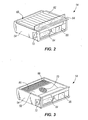
- FIG. 2 is a perspective view of one of the modular refrigeration units of FIG.
1.
- FIG. 3 is a perspective view of the modular refrigeration unit of FIG. 2,
illustrating a support panel or shelf removed.
- FIG. 4 is a cross-sectional view of the modular refrigeration system of FIG. 1,
taken along line 4-4.
-
-
Before any features of the invention are explained in detail, it is to be
understood that the invention is not limited in its application to the details of
construction and the arrangements of the components set forth in the following
description or illustrated in the drawings. The invention is capable of other
embodiments and of being practiced or being carried out in various ways. Also, it is
understood that the phraseology and terminology used herein is for the purpose of
description and should not be regarded as limiting. The use of "including" and
"comprising" and variations thereof herein is meant to encompass the items listed
thereafter and equivalents thereof as well as additional items. The use of letters to
identify elements of a method or process is simply for identification and is not meant
to indicate that the elements should be performed in a particular order.
DETAILED DESCRIPTION
-
Referring to FIG. 1, a modular refrigeration system is shown comprising a
refrigerated merchandiser 10 and a plurality of modular refrigeration units 14 that are
removably coupled to the merchandiser 10. Although the exemplary merchandiser 10
of FIG. 1 is configured to be positioned against a wall, the merchandiser 10 of the
present invention may also include any of a number of different forms of
merchandisers (e.g., an island merchandiser, a convertible merchandiser, a service
merchandiser, and so forth).
-
The refrigerated merchandiser 10 includes a case 18 generally defining an
interior rear wall 22 and an interior top wall 26, while each modular refrigeration unit
14, when coupled to the merchandiser 10, generally defines at least a portion of an
interior bottom wall 30 of the case 18. The area bounded by the interior bottom wall
30, interior rear wall 22, and the interior top wall 26 defines a refrigerated
compartment, or a product display area 34, in which food and/or beverage products
are stored on a plurality of shelves 38. The case 18 includes an open front face to
allow customers access to the food and/or beverages stored in the case 18.
Alternatively, the product display area 34 may be enclosed by hinged or sliding front
door panels.
-
The case 18 also generally defines an exterior rear wall 40 adjacent the interior
rear wall 22 and an exterior top wall 42 adjacent the interior top wall 26. A rear flue
27 is defined between the interior and exterior rear walls 22, 40 to allow for a
substantially vertical refrigerated airflow 28 throughout the rear flue 27. An opening
29 into the rear flue 27 is defined between the interior and exterior rear walls toward
the bottom of the merchandiser 10. An upper flue 31 is defined between the interior
and exterior top walls 26, 42 and is fluidly connected with and adjacent to the rear
flue 27. The upper flue 31 allows for substantially horizontal airflow 32 throughout
the upper flue 31. The interior top wall 26 includes an opening 33 to communicate
with the upper flue 31 and allow the airflow 32 in the upper flue 31 to be discharged
from the upper flue 31 into the product display area 34.
-
The interior rear wall 22 includes a plurality of apertures 35 therein. The
apertures 35 may be positioned in groups along the height of the interior rear wall 22
to fluidly connect the product display area 34 and the rear flue 27. The apertures 35
allow some of the refrigerated air of the airflow 28 in the rear flue 27 to exit the rear
flue 27 and enter the product display area 34. Products located in the product display
area 34 may then be cooled by the refrigerated air.
-
The remaining portion of the refrigerated airflow 28 that does not pass
through the apertures 35 is routed vertically through the rear flue 27, and horizontally
through the upper flue 31 before being discharged from the upper flue 31 via the
opening 33 in the interior top wall 26. After being discharged from the opening 33 in
the interior top wall 26, the refrigerated air moves downwardly along the open front
face of the refrigerated merchandiser 10 to form an air curtain 36 over the open front
face of the case 18.
-
A plurality of spaces in the bottom of the merchandiser 10 generally define a
plurality of accessible compartments 46 capable of accommodating a single modular
refrigeration unit 14. As shown in FIG. 1, the modular refrigeration units 14 are
removably coupled with the merchandiser 10 via brackets 50 in each accessible
compartment 46. In the illustrated construction, brackets 50 are positioned on
opposing sides in each accessible compartment 46 to support the respective opposing
sides of each modular refrigeration unit 14. The brackets 50 may be configured in
any of a number of conventional forms to inter-engage corresponding structure (not
shown) on the modular refrigeration units 14. Alternatively, the modular refrigeration
units 14 may be coupled to their respective accessible compartments 46 via other
methods known to those skilled in the art.
-
Each modular refrigeration unit 14 generally includes a housing 54
substantially enclosing the refrigeration components of the refrigeration system. In
addition, the housing 54 generally at least partially defines a lower flue 37 between a
fan plenum 58 (see FIG. 3) of the housing 54 and a bottom wall 59 of the housing 54
through which the refrigerated air produced by the refrigeration components is
allowed to move. Each refrigeration unit 14 may also include a shelf 62 supported on
the top portion of the housing 54 to support products thereon.
-
The lower flue 37 may also be at least partially defined between the shelf 62
and the fan plenum 58, such that incoming return air from the air curtain 36 may enter
the lower flue 37 via one or more openings 39 in the front portion of the top shelf 62
or a gap between the front edge of the top shelf 62 and the housing 54 to be drawn
into the housing 54. A filter 64 may be positioned in the gap between the front edge
of the top shelf 62 and the housing 54 or adjacent the one or more openings 39 in the
top shelf 62 such that debris and/or dust may be filtered from the incoming return air
from the air curtain 36. The filter 64 may be configured in any of a number of
different forms such that particulate debris entrained in the incoming return air is
separated from the incoming return air, while the filtered incoming return air is
allowed to pass through the filter 64. In addition, cooled air discharged from the
housing 54 may exit the lower flue 37 via a gap 68 between the rear edge of the top
shelf 62 and the housing 54.
-
Upon coupling the modular refrigeration unit 14 and the merchandiser 10, the
lower flue 37 is fluidly connected with the rear flue 27 via the gap 68 between the rear
edge of the top shelf 62 and the housing 54, and into the rear flue 27 via the opening
29 in the rear flue 27. When combined, the lower flue 37, the rear flue 27, and the
upper flue 31 comprise an air passage 41 separate from the product display area 34.
-
Each modular refrigeration unit 14 includes refrigeration components, such as
an evaporator assembly and a condenser assembly, supported by the housing 54. The
evaporator and condenser assemblies may be separated from each other by a dividing
wall 72 in the housing 54.
-
The evaporator assembly may include an evaporator 80 and a motorized fan
81 to move air through the evaporator 80. As shown in FIG. 3, the evaporator 80 is
positioned substantially horizontally in the discharge opening 66 of the housing 54.
In addition, the fan is positioned adjacent the fan plenum 58 to draw an airflow 43
through the intake opening 70. In the illustrated construction of the modular
refrigeration unit 14, the fan draws the airflow 43 into the housing 54 such that the
airflow 43 is upwardly re-directed by a bottom wall 59 of the housing 54 to flow
horizontally through the evaporator 80 for cooling. Alternatively, the evaporator 80
may be oriented substantially vertically in the discharge opening 66 such that the
airflow 43 is caused to travel a different path (e.g., vertically) to exit the housing 54.
As a further alternative, the evaporator 80 may extend above the upper portions of the
housing 54, such that a notch is required in the case 18 to allow clearance for the
evaporator 80 when inserting the modular refrigeration unit 14 into the accessible
compartment 46. The housing 54 may then include an upstanding panel to
complement, or "fill in" the notch in the case 18 when the modular refrigeration unit
14 is inserted into the accessible compartment 46.
-
Multiple fans may also be used to move air through the evaporator 80. The
evaporator assembly may also include an expansion valve to provide the modular
refrigeration unit 14 with a desired refrigeration capacity.
-
The condenser assembly may include a compressor 84, a motorized fan (not
shown), and a condenser 88. To decrease the amount of vibration transmitted by the
compressor 84, the compressor 84 may be mounted to the housing 54 through
vibration damping mounts. The condenser 88 may be mounted to the housing 54
through a support tray, and the fan may be mounted to the condenser 88. The
condenser assembly may also include a receiver (not shown) in which to store liquid
refrigerant. With reference to FIGS. 2-3, the fan may generate an airflow through the
condenser 88 in any of a number of different directions. In the illustrated
construction, the fan may generate an airflow moving from side to side of the housing
54 or from front to back of the housing 54. In other embodiments, the condenser 88
can be fluid cooled by, for example, a glycol solution provided by a central fluid
distribution system, which supplies cooling fluid to each of the modular refrigeration
units 14. In this embodiment, cooling lines of the condenser unit can be coupled to
the central fluid distribution system when the modular refrigeration unit 14 is installed
into the refrigerated merchandiser 10.
-
Refrigerant may be circulated in a closed circuit between the evaporator
assembly and the condenser assembly, leaving the evaporator as a low-pressure gas
for compression by the compressor. From the compressor 84, the refrigerant may be
discharged through the condenser 88, in which the refrigerant is substantially
condensed to a high-pressure liquid before being fed to the evaporator assembly by an
expansion valve.
-
The modular refrigeration units 14 may be powered using line power. The
merchandiser 10 may include a power distribution system (not shown) to distribute
power from a single source of line power (e.g., a power cord) to the one or more
modular refrigeration units 14. The power distribution system may include electrical
connectors (e.g., conventional quick-release electrical connectors, not shown)
positioned in the accessible compartments 46 that are configured to engage mating
electrical connectors (not shown) coupled to the individual modular refrigeration units
14. Further, the electrical connectors coupled to the individual modular refrigeration
units 14 may be electrically connected to one or more of the refrigeration components
(e.g., the compressor 84) to provide line power distributed by the power distribution
system.
-
Since all of the refrigeration components associated with providing a
refrigerated airflow to the product display area 34 are located in the housing 54 of the
modular refrigeration unit 14, repairs to the refrigeration components may be readily
performed without affecting the products stored in the product display area 34. For
example, if a particular modular refrigeration unit 14 stops functioning, it can be
easily replaced with a functioning stand-by modular refrigeration unit 14 to avoid loss
of any of the refrigerated products. The non-functioning or ill-functioning modular
refrigeration unit 14 may then be repaired at a location remote from the merchandiser
10.
-
In addition, since the modular refrigeration units 14 are self-contained, a
skilled technician may not be required to install and/or remove the modular
refrigeration unit 14 from the merchandiser 10. Rather, if repairs are required of a
particular modular refrigeration unit 14, it may be removed from the merchandiser 10
by an employee of the retail store in which the merchandiser 10 is used, and shipped
to a repair facility for repair by a skilled technician. As a result, the costs associated
with maintaining the merchandiser 10 may be reduced compared to a conventional
merchandiser.
-
Each modular refrigeration unit 14 may be independently configured to
provide a desired refrigeration capacity. As a result, the plurality of modular
refrigeration units 14 may provide the product display area 34 with a plurality of
different refrigeration zones. A refrigeration zone may be considered a portion of the
product display area 34 that is maintained at a different temperature than an adjacent
portion of the product display area 34. In the illustrated construction of FIG. 1, four
modular refrigeration units 14 are shown that could potentially be configured to
provide the product display area 34 with four different refrigeration zones in which to
store products. By providing the capability of multiple different refrigeration zones in
a single merchandiser 10, the usefulness of the merchandiser 10 is enhanced as being
able to store a wider variety of products, as opposed to a conventional merchandiser,
which has a fixed refrigeration capacity and may only be suited to store a narrow
range of products.
-
The modular refrigeration units 14 are interchangeable with one another, such
that the refrigeration zones in the product display area 34 may be re-configured by
interchanging one modular refrigeration unit 14 for another. This allows the
merchandiser 10 to be tailored to the products to be stored therein, as opposed to
conventional merchandisers, which are custom-built to store a particular range of
products.
-
Each modular refrigeration unit 14 may be constructed having a pre-selected
refrigeration capacity. Alternatively, each modular refrigeration unit 14 may include
user-manipulatable controls (not shown) accessible to an operator to vary the
refrigeration capacity of the modular refrigeration unit 14. For example, such user-manipulatable
controls may be configured to adjust a temperature level of the modular
refrigeration unit 14, which, in turn, may adjust the capacity of the compressor. The
user manipulatable controls may be located in a front panel 78 of each refrigeration
unit 14. A display window 82 on the front panel may display the temperature on
which the refrigeration unit 14 is set. Additionally, the user manipulatable controls
may be located within the display window 82.
-
A plurality of dividing walls 74 may also be positioned in the rear flue 27
and/or the upper flue 31 of the merchandiser 10 to fluidly separate the rear flue 27
and/or the upper flue 31 into a plurality of rear flues 27 and/or upper flues 31
associated with the plurality of modular refrigeration units 14. As a result, the
refrigerated airflow from each modular refrigeration unit 14 may be maintained
within its associated rear flue 27 and/or upper flue 31 before being discharged into the
product display area 34.