EP1547492A2 - Modular refrigeration system - Google Patents
Modular refrigeration system Download PDFInfo
- Publication number
- EP1547492A2 EP1547492A2 EP04257770A EP04257770A EP1547492A2 EP 1547492 A2 EP1547492 A2 EP 1547492A2 EP 04257770 A EP04257770 A EP 04257770A EP 04257770 A EP04257770 A EP 04257770A EP 1547492 A2 EP1547492 A2 EP 1547492A2
- Authority
- EP
- European Patent Office
- Prior art keywords
- refrigeration unit
- refrigeration
- modular
- zone
- modular refrigeration
- Prior art date
- Legal status (The legal status is an assumption and is not a legal conclusion. Google has not performed a legal analysis and makes no representation as to the accuracy of the status listed.)
- Withdrawn
Links
Images


Classifications
-
- A—HUMAN NECESSITIES
- A47—FURNITURE; DOMESTIC ARTICLES OR APPLIANCES; COFFEE MILLS; SPICE MILLS; SUCTION CLEANERS IN GENERAL
- A47F—SPECIAL FURNITURE, FITTINGS, OR ACCESSORIES FOR SHOPS, STOREHOUSES, BARS, RESTAURANTS OR THE LIKE; PAYING COUNTERS
- A47F3/00—Show cases or show cabinets
- A47F3/04—Show cases or show cabinets air-conditioned, refrigerated
- A47F3/0482—Details common to both closed and open types
-
- A—HUMAN NECESSITIES
- A47—FURNITURE; DOMESTIC ARTICLES OR APPLIANCES; COFFEE MILLS; SPICE MILLS; SUCTION CLEANERS IN GENERAL
- A47F—SPECIAL FURNITURE, FITTINGS, OR ACCESSORIES FOR SHOPS, STOREHOUSES, BARS, RESTAURANTS OR THE LIKE; PAYING COUNTERS
- A47F3/00—Show cases or show cabinets
- A47F3/04—Show cases or show cabinets air-conditioned, refrigerated
- A47F3/0439—Cases or cabinets of the open type
- A47F3/0443—Cases or cabinets of the open type with forced air circulation
Definitions
- This invention relates to a refrigeration system for a refrigerated merchandiser of the type used in retail stores, convenience stores, snack bars, and restaurants for storing and cooling food and/or beverage products.
- refrigerated merchandisers have a refrigerated compartment or product display area that is accessible to a consumer through an open face of the merchandiser or through glass doors which may be hinged or which may slide for easy access to the display shelves positioned within the product display area.
- the product display area is typically cooled by a refrigeration system that includes an evaporator assembly and a condenser assembly arranged in a closed circuit.
- the evaporator assembly generally including an evaporator, fan, and expansion valve
- the condenser assembly generally including a compressor and a condenser
- one or more compressors may be positioned in a back room to compress the refrigerant, while one or more condensers may be positioned on the rooftop of the retail store to receive compressed, substantially vaporized refrigerant from the compressor and discharge pressurized, substantially liquid refrigerant to evaporators that are individually positioned in the merchandisers.
- the pressurized, substantially liquid refrigerant is metered to the evaporator by the expansion valve.
- the fan distributes incoming return air from the product display area through the evaporator, where heat exchange between the return air and the refrigerant occurs, to reintroduce cooled air into the product display area.
- the refrigerant exits the evaporator in a substantially vaporized state and is drawn back into the compressor to repeat the refrigeration cycle.
- the evaporator assembly is typically sized to provide the product display area of the merchandiser with a fixed refrigeration capacity.
- the merchandiser may only be suited to store a narrow range of products, and dedicated merchandiser configurations may be required to store specific products.
- a modular refrigeration system for use in cooling a product display area of a refrigerated merchandiser.
- the refrigeration system comprises one or more modular refrigeration units that are positionable in an accessible compartment of the merchandiser and are capable of cooling at least a portion of the product display area of the merchandiser.
- the modular refrigeration units can be easily installed into and removed from the accessible compartment.
- the refrigeration units may also be interchangeable with one another.
- a refrigerated merchandiser can include a case including a first accessible compartment and a second accessible compartment spaced from the first accessible compartment.
- the refrigerated merchandiser can further include a first modular refrigeration unit configured to be installed into the first accessible compartment such that the first modular refrigeration unit is in fluid communication with a first refrigeration zone when installed in the first accessible compartment to maintain the first refrigeration zone at a first temperature.
- the first modular refrigeration unit can include a first evaporator assembly and a first condenser assembly.
- the refrigerated merchandiser can further include a second modular refrigeration unit configured to be installed into the second accessible compartment such that the second modular refrigeration unit is in fluid communication with a second refrigeration zone when installed in the second accessible compartment to maintain the second refrigeration zone at a second temperature.
- the second modular refrigeration unit can include a second evaporator assembly and a second condenser assembly.
- a method for operating a refrigerated merchandiser can include providing a first refrigerated zone in a case of the refrigerated merchandiser, and providing a second refrigerated zone in the case.
- the method can further include removably positioning a first modular refrigeration unit in the refrigerated merchandiser such that the first modular refrigeration unit is in fluid communication with the first refrigerated zone.
- the first modular refrigeration unit can include an evaporator assembly and a condenser assembly.
- the method can further include maintaining the first refrigerated zone at a first temperature with the first modular refrigeration unit.
- the method can further include removably positioning a second modular refrigeration unit in the refrigerated merchandiser such that the second modular refrigeration unit is in fluid communication with the second refrigerated zone.
- the second modular refrigeration unit can include an evaporator assembly and a condenser assembly.
- the method can further include maintaining the second refrigerated zone at a second temperature with the second modular refrigeration unit.
- a refrigerated merchandiser including a case, and a first modular refrigeration unit removably coupled to the case in fluid communication with a first refrigeration zone to maintain the first refrigeration zone at a first temperature.
- the first modular refrigeration unit can include an evaporator assembly and a condenser assembly.
- the refrigerated merchandiser can further include a second modular refrigeration unit removably coupled to the case in fluid communication with a second refrigeration zone to maintain the second refrigeration zone at a second temperature.
- the second modular refrigeration unit can include an evaporator assembly and a condenser assembly.
- a modular refrigeration system comprising a refrigerated merchandiser 10 and a plurality of modular refrigeration units 14 that are removably coupled to the merchandiser 10.
- the exemplary merchandiser 10 of FIG. 1 is configured to be positioned against a wall, the merchandiser 10 of the present invention may also include any of a number of different forms of merchandisers (e.g., an island merchandiser, a convertible merchandiser, a service merchandiser, and so forth).
- the refrigerated merchandiser 10 includes a case 18 generally defining an interior rear wall 22 and an interior top wall 26, while each modular refrigeration unit 14, when coupled to the merchandiser 10, generally defines at least a portion of an interior bottom wall 30 of the case 18.
- the area bounded by the interior bottom wall 30, interior rear wall 22, and the interior top wall 26 defines a refrigerated compartment, or a product display area 34, in which food and/or beverage products are stored on a plurality of shelves 38.
- the case 18 includes an open front face to allow customers access to the food and/or beverages stored in the case 18.
- the product display area 34 may be enclosed by hinged or sliding front door panels.
- the case 18 also generally defines an exterior rear wall 40 adjacent the interior rear wall 22 and an exterior top wall 42 adjacent the interior top wall 26.
- a rear flue 27 is defined between the interior and exterior rear walls 22, 40 to allow for a substantially vertical refrigerated airflow 28 throughout the rear flue 27.
- An opening 29 into the rear flue 27 is defined between the interior and exterior rear walls toward the bottom of the merchandiser 10.
- An upper flue 31 is defined between the interior and exterior top walls 26, 42 and is fluidly connected with and adjacent to the rear flue 27. The upper flue 31 allows for substantially horizontal airflow 32 throughout the upper flue 31.
- the interior top wall 26 includes an opening 33 to communicate with the upper flue 31 and allow the airflow 32 in the upper flue 31 to be discharged from the upper flue 31 into the product display area 34.
- the interior rear wall 22 includes a plurality of apertures 35 therein.
- the apertures 35 may be positioned in groups along the height of the interior rear wall 22 to fluidly connect the product display area 34 and the rear flue 27.
- the apertures 35 allow some of the refrigerated air of the airflow 28 in the rear flue 27 to exit the rear flue 27 and enter the product display area 34. Products located in the product display area 34 may then be cooled by the refrigerated air.
- the remaining portion of the refrigerated airflow 28 that does not pass through the apertures 35 is routed vertically through the rear flue 27, and horizontally through the upper flue 31 before being discharged from the upper flue 31 via the opening 33 in the interior top wall 26. After being discharged from the opening 33 in the interior top wall 26, the refrigerated air moves downwardly along the open front face of the refrigerated merchandiser 10 to form an air curtain 36 over the open front face of the case 18.
- a plurality of spaces in the bottom of the merchandiser 10 generally define a plurality of accessible compartments 46 capable of accommodating a single modular refrigeration unit 14.
- the modular refrigeration units 14 are removably coupled with the merchandiser 10 via brackets 50 in each accessible compartment 46.
- brackets 50 are positioned on opposing sides in each accessible compartment 46 to support the respective opposing sides of each modular refrigeration unit 14.
- the brackets 50 may be configured in any of a number of conventional forms to inter-engage corresponding structure (not shown) on the modular refrigeration units 14.
- the modular refrigeration units 14 may be coupled to their respective accessible compartments 46 via other methods known to those skilled in the art.
- Each modular refrigeration unit 14 generally includes a housing 54 substantially enclosing the refrigeration components of the refrigeration system.
- the housing 54 generally at least partially defines a lower flue 37 between a fan plenum 58 (see FIG. 3) of the housing 54 and a bottom wall 59 of the housing 54 through which the refrigerated air produced by the refrigeration components is allowed to move.
- Each refrigeration unit 14 may also include a shelf 62 supported on the top portion of the housing 54 to support products thereon.
- the lower flue 37 may also be at least partially defined between the shelf 62 and the fan plenum 58, such that incoming return air from the air curtain 36 may enter the lower flue 37 via one or more openings 39 in the front portion of the top shelf 62 or a gap between the front edge of the top shelf 62 and the housing 54 to be drawn into the housing 54.
- a filter 64 may be positioned in the gap between the front edge of the top shelf 62 and the housing 54 or adjacent the one or more openings 39 in the top shelf 62 such that debris and/or dust may be filtered from the incoming return air from the air curtain 36.
- the filter 64 may be configured in any of a number of different forms such that particulate debris entrained in the incoming return air is separated from the incoming return air, while the filtered incoming return air is allowed to pass through the filter 64.
- cooled air discharged from the housing 54 may exit the lower flue 37 via a gap 68 between the rear edge of the top shelf 62 and the housing 54.
- the lower flue 37 Upon coupling the modular refrigeration unit 14 and the merchandiser 10, the lower flue 37 is fluidly connected with the rear flue 27 via the gap 68 between the rear edge of the top shelf 62 and the housing 54, and into the rear flue 27 via the opening 29 in the rear flue 27.
- the lower flue 37, the rear flue 27, and the upper flue 31 comprise an air passage 41 separate from the product display area 34.
- Each modular refrigeration unit 14 includes refrigeration components, such as an evaporator assembly and a condenser assembly, supported by the housing 54.
- the evaporator and condenser assemblies may be separated from each other by a dividing wall 72 in the housing 54.
- the evaporator assembly may include an evaporator 80 and a motorized fan 81 to move air through the evaporator 80.
- the evaporator 80 is positioned substantially horizontally in the discharge opening 66 of the housing 54.
- the fan is positioned adjacent the fan plenum 58 to draw an airflow 43 through the intake opening 70.
- the fan draws the airflow 43 into the housing 54 such that the airflow 43 is upwardly re-directed by a bottom wall 59 of the housing 54 to flow horizontally through the evaporator 80 for cooling.
- the evaporator 80 may be oriented substantially vertically in the discharge opening 66 such that the airflow 43 is caused to travel a different path (e.g., vertically) to exit the housing 54.
- the evaporator 80 may extend above the upper portions of the housing 54, such that a notch is required in the case 18 to allow clearance for the evaporator 80 when inserting the modular refrigeration unit 14 into the accessible compartment 46.
- the housing 54 may then include an upstanding panel to complement, or "fill in” the notch in the case 18 when the modular refrigeration unit 14 is inserted into the accessible compartment 46.
- the evaporator assembly may also include an expansion valve to provide the modular refrigeration unit 14 with a desired refrigeration capacity.
- the condenser assembly may include a compressor 84, a motorized fan (not shown), and a condenser 88.
- the compressor 84 may be mounted to the housing 54 through vibration damping mounts.
- the condenser 88 may be mounted to the housing 54 through a support tray, and the fan may be mounted to the condenser 88.
- the condenser assembly may also include a receiver (not shown) in which to store liquid refrigerant.
- the fan may generate an airflow through the condenser 88 in any of a number of different directions. In the illustrated construction, the fan may generate an airflow moving from side to side of the housing 54 or from front to back of the housing 54.
- the condenser 88 can be fluid cooled by, for example, a glycol solution provided by a central fluid distribution system, which supplies cooling fluid to each of the modular refrigeration units 14.
- cooling lines of the condenser unit can be coupled to the central fluid distribution system when the modular refrigeration unit 14 is installed into the refrigerated merchandiser 10.
- Refrigerant may be circulated in a closed circuit between the evaporator assembly and the condenser assembly, leaving the evaporator as a low-pressure gas for compression by the compressor. From the compressor 84, the refrigerant may be discharged through the condenser 88, in which the refrigerant is substantially condensed to a high-pressure liquid before being fed to the evaporator assembly by an expansion valve.
- the modular refrigeration units 14 may be powered using line power.
- the merchandiser 10 may include a power distribution system (not shown) to distribute power from a single source of line power (e.g., a power cord) to the one or more modular refrigeration units 14.
- the power distribution system may include electrical connectors (e.g., conventional quick-release electrical connectors, not shown) positioned in the accessible compartments 46 that are configured to engage mating electrical connectors (not shown) coupled to the individual modular refrigeration units 14.
- the electrical connectors coupled to the individual modular refrigeration units 14 may be electrically connected to one or more of the refrigeration components (e.g., the compressor 84) to provide line power distributed by the power distribution system.
- the modular refrigeration units 14 are self-contained, a skilled technician may not be required to install and/or remove the modular refrigeration unit 14 from the merchandiser 10. Rather, if repairs are required of a particular modular refrigeration unit 14, it may be removed from the merchandiser 10 by an employee of the retail store in which the merchandiser 10 is used, and shipped to a repair facility for repair by a skilled technician. As a result, the costs associated with maintaining the merchandiser 10 may be reduced compared to a conventional merchandiser.
- Each modular refrigeration unit 14 may be independently configured to provide a desired refrigeration capacity.
- the plurality of modular refrigeration units 14 may provide the product display area 34 with a plurality of different refrigeration zones.
- a refrigeration zone may be considered a portion of the product display area 34 that is maintained at a different temperature than an adjacent portion of the product display area 34.
- four modular refrigeration units 14 are shown that could potentially be configured to provide the product display area 34 with four different refrigeration zones in which to store products.
- the modular refrigeration units 14 are interchangeable with one another, such that the refrigeration zones in the product display area 34 may be re-configured by interchanging one modular refrigeration unit 14 for another. This allows the merchandiser 10 to be tailored to the products to be stored therein, as opposed to conventional merchandisers, which are custom-built to store a particular range of products.
- Each modular refrigeration unit 14 may be constructed having a pre-selected refrigeration capacity.
- each modular refrigeration unit 14 may include user-manipulatable controls (not shown) accessible to an operator to vary the refrigeration capacity of the modular refrigeration unit 14.
- user-manipulatable controls may be configured to adjust a temperature level of the modular refrigeration unit 14, which, in turn, may adjust the capacity of the compressor.
- the user manipulatable controls may be located in a front panel 78 of each refrigeration unit 14.
- a display window 82 on the front panel may display the temperature on which the refrigeration unit 14 is set. Additionally, the user manipulatable controls may be located within the display window 82.
- a plurality of dividing walls 74 may also be positioned in the rear flue 27 and/or the upper flue 31 of the merchandiser 10 to fluidly separate the rear flue 27 and/or the upper flue 31 into a plurality of rear flues 27 and/or upper flues 31 associated with the plurality of modular refrigeration units 14.
- the refrigerated airflow from each modular refrigeration unit 14 may be maintained within its associated rear flue 27 and/or upper flue 31 before being discharged into the product display area 34.
Abstract
Description
- Priority benefit is claimed to U.S. Provisional Patent Application Serial No. 60/529,556, filed December 15, 2003.
- This invention relates to a refrigeration system for a refrigerated merchandiser of the type used in retail stores, convenience stores, snack bars, and restaurants for storing and cooling food and/or beverage products.
- Typically, refrigerated merchandisers have a refrigerated compartment or product display area that is accessible to a consumer through an open face of the merchandiser or through glass doors which may be hinged or which may slide for easy access to the display shelves positioned within the product display area. The product display area is typically cooled by a refrigeration system that includes an evaporator assembly and a condenser assembly arranged in a closed circuit. Typically, the evaporator assembly, generally including an evaporator, fan, and expansion valve, is positioned in the merchandiser, while the condenser assembly, generally including a compressor and a condenser, is remotely positioned from the merchandiser.
- In a retail store setting including multiple refrigerated merchandisers in a closed-circuit refrigeration system, one or more compressors may be positioned in a back room to compress the refrigerant, while one or more condensers may be positioned on the rooftop of the retail store to receive compressed, substantially vaporized refrigerant from the compressor and discharge pressurized, substantially liquid refrigerant to evaporators that are individually positioned in the merchandisers.
- In the merchandiser, the pressurized, substantially liquid refrigerant is metered to the evaporator by the expansion valve. The fan distributes incoming return air from the product display area through the evaporator, where heat exchange between the return air and the refrigerant occurs, to reintroduce cooled air into the product display area. The refrigerant exits the evaporator in a substantially vaporized state and is drawn back into the compressor to repeat the refrigeration cycle.
- In addition, the evaporator assembly is typically sized to provide the product display area of the merchandiser with a fixed refrigeration capacity. As a result, the merchandiser may only be suited to store a narrow range of products, and dedicated merchandiser configurations may be required to store specific products.
- In accordance with one aspect of the invention, there is provided a modular refrigeration system for use in cooling a product display area of a refrigerated merchandiser. The refrigeration system comprises one or more modular refrigeration units that are positionable in an accessible compartment of the merchandiser and are capable of cooling at least a portion of the product display area of the merchandiser. The modular refrigeration units can be easily installed into and removed from the accessible compartment. The refrigeration units may also be interchangeable with one another.
- Some embodiments of the present invention provide a refrigerated merchandiser that can include a case including a first accessible compartment and a second accessible compartment spaced from the first accessible compartment. The refrigerated merchandiser can further include a first modular refrigeration unit configured to be installed into the first accessible compartment such that the first modular refrigeration unit is in fluid communication with a first refrigeration zone when installed in the first accessible compartment to maintain the first refrigeration zone at a first temperature. The first modular refrigeration unit can include a first evaporator assembly and a first condenser assembly. The refrigerated merchandiser can further include a second modular refrigeration unit configured to be installed into the second accessible compartment such that the second modular refrigeration unit is in fluid communication with a second refrigeration zone when installed in the second accessible compartment to maintain the second refrigeration zone at a second temperature. The second modular refrigeration unit can include a second evaporator assembly and a second condenser assembly.
- In some embodiments of the present invention, a method for operating a refrigerated merchandiser is provided. The method can include providing a first refrigerated zone in a case of the refrigerated merchandiser, and providing a second refrigerated zone in the case. The method can further include removably positioning a first modular refrigeration unit in the refrigerated merchandiser such that the first modular refrigeration unit is in fluid communication with the first refrigerated zone. The first modular refrigeration unit can include an evaporator assembly and a condenser assembly. The method can further include maintaining the first refrigerated zone at a first temperature with the first modular refrigeration unit. The method can further include removably positioning a second modular refrigeration unit in the refrigerated merchandiser such that the second modular refrigeration unit is in fluid communication with the second refrigerated zone. The second modular refrigeration unit can include an evaporator assembly and a condenser assembly. The method can further include maintaining the second refrigerated zone at a second temperature with the second modular refrigeration unit.
- Some embodiments of the present invention provide a refrigerated merchandiser including a case, and a first modular refrigeration unit removably coupled to the case in fluid communication with a first refrigeration zone to maintain the first refrigeration zone at a first temperature. The first modular refrigeration unit can include an evaporator assembly and a condenser assembly. The refrigerated merchandiser can further include a second modular refrigeration unit removably coupled to the case in fluid communication with a second refrigeration zone to maintain the second refrigeration zone at a second temperature. The second modular refrigeration unit can include an evaporator assembly and a condenser assembly.
- Other features and aspects of the present invention will become apparent to those skilled in the art upon review of the following detailed description and drawings.
- In the drawings, wherein like reference numerals indicate like parts:
- FIG. 1 is a perspective view of the modular refrigeration system of the present invention, illustrating multiple modular refrigeration units coupled to a refrigerated merchandiser.
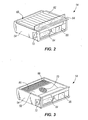
- FIG. 2 is a perspective view of one of the modular refrigeration units of FIG. 1.
- FIG. 3 is a perspective view of the modular refrigeration unit of FIG. 2, illustrating a support panel or shelf removed.
- FIG. 4 is a cross-sectional view of the modular refrigeration system of FIG. 1, taken along line 4-4.
-
- Before any features of the invention are explained in detail, it is to be understood that the invention is not limited in its application to the details of construction and the arrangements of the components set forth in the following description or illustrated in the drawings. The invention is capable of other embodiments and of being practiced or being carried out in various ways. Also, it is understood that the phraseology and terminology used herein is for the purpose of description and should not be regarded as limiting. The use of "including" and "comprising" and variations thereof herein is meant to encompass the items listed thereafter and equivalents thereof as well as additional items. The use of letters to identify elements of a method or process is simply for identification and is not meant to indicate that the elements should be performed in a particular order.
- Referring to FIG. 1, a modular refrigeration system is shown comprising a refrigerated
merchandiser 10 and a plurality ofmodular refrigeration units 14 that are removably coupled to themerchandiser 10. Although theexemplary merchandiser 10 of FIG. 1 is configured to be positioned against a wall, themerchandiser 10 of the present invention may also include any of a number of different forms of merchandisers (e.g., an island merchandiser, a convertible merchandiser, a service merchandiser, and so forth). - The refrigerated
merchandiser 10 includes acase 18 generally defining an interiorrear wall 22 and aninterior top wall 26, while eachmodular refrigeration unit 14, when coupled to themerchandiser 10, generally defines at least a portion of aninterior bottom wall 30 of thecase 18. The area bounded by theinterior bottom wall 30, interiorrear wall 22, and theinterior top wall 26 defines a refrigerated compartment, or aproduct display area 34, in which food and/or beverage products are stored on a plurality ofshelves 38. Thecase 18 includes an open front face to allow customers access to the food and/or beverages stored in thecase 18. Alternatively, theproduct display area 34 may be enclosed by hinged or sliding front door panels. - The
case 18 also generally defines an exteriorrear wall 40 adjacent theinterior rear wall 22 and anexterior top wall 42 adjacent theinterior top wall 26. Arear flue 27 is defined between the interior and exteriorrear walls airflow 28 throughout therear flue 27. An opening 29 into therear flue 27 is defined between the interior and exterior rear walls toward the bottom of themerchandiser 10. Anupper flue 31 is defined between the interior andexterior top walls rear flue 27. Theupper flue 31 allows for substantiallyhorizontal airflow 32 throughout theupper flue 31. Theinterior top wall 26 includes anopening 33 to communicate with theupper flue 31 and allow theairflow 32 in theupper flue 31 to be discharged from theupper flue 31 into theproduct display area 34. - The interior
rear wall 22 includes a plurality ofapertures 35 therein. Theapertures 35 may be positioned in groups along the height of the interiorrear wall 22 to fluidly connect theproduct display area 34 and therear flue 27. Theapertures 35 allow some of the refrigerated air of theairflow 28 in therear flue 27 to exit therear flue 27 and enter theproduct display area 34. Products located in theproduct display area 34 may then be cooled by the refrigerated air. - The remaining portion of the refrigerated
airflow 28 that does not pass through theapertures 35 is routed vertically through therear flue 27, and horizontally through theupper flue 31 before being discharged from theupper flue 31 via theopening 33 in the interiortop wall 26. After being discharged from theopening 33 in the interiortop wall 26, the refrigerated air moves downwardly along the open front face of therefrigerated merchandiser 10 to form anair curtain 36 over the open front face of thecase 18. - A plurality of spaces in the bottom of the merchandiser 10 generally define a plurality of
accessible compartments 46 capable of accommodating a singlemodular refrigeration unit 14. As shown in FIG. 1, themodular refrigeration units 14 are removably coupled with themerchandiser 10 viabrackets 50 in eachaccessible compartment 46. In the illustrated construction,brackets 50 are positioned on opposing sides in eachaccessible compartment 46 to support the respective opposing sides of eachmodular refrigeration unit 14. Thebrackets 50 may be configured in any of a number of conventional forms to inter-engage corresponding structure (not shown) on themodular refrigeration units 14. Alternatively, themodular refrigeration units 14 may be coupled to their respectiveaccessible compartments 46 via other methods known to those skilled in the art. - Each
modular refrigeration unit 14 generally includes ahousing 54 substantially enclosing the refrigeration components of the refrigeration system. In addition, thehousing 54 generally at least partially defines alower flue 37 between a fan plenum 58 (see FIG. 3) of thehousing 54 and abottom wall 59 of thehousing 54 through which the refrigerated air produced by the refrigeration components is allowed to move. Eachrefrigeration unit 14 may also include ashelf 62 supported on the top portion of thehousing 54 to support products thereon. - The
lower flue 37 may also be at least partially defined between theshelf 62 and thefan plenum 58, such that incoming return air from theair curtain 36 may enter thelower flue 37 via one ormore openings 39 in the front portion of thetop shelf 62 or a gap between the front edge of thetop shelf 62 and thehousing 54 to be drawn into thehousing 54. Afilter 64 may be positioned in the gap between the front edge of thetop shelf 62 and thehousing 54 or adjacent the one ormore openings 39 in thetop shelf 62 such that debris and/or dust may be filtered from the incoming return air from theair curtain 36. Thefilter 64 may be configured in any of a number of different forms such that particulate debris entrained in the incoming return air is separated from the incoming return air, while the filtered incoming return air is allowed to pass through thefilter 64. In addition, cooled air discharged from thehousing 54 may exit thelower flue 37 via agap 68 between the rear edge of thetop shelf 62 and thehousing 54. - Upon coupling the
modular refrigeration unit 14 and themerchandiser 10, thelower flue 37 is fluidly connected with therear flue 27 via thegap 68 between the rear edge of thetop shelf 62 and thehousing 54, and into therear flue 27 via theopening 29 in therear flue 27. When combined, thelower flue 37, therear flue 27, and theupper flue 31 comprise anair passage 41 separate from theproduct display area 34. - Each
modular refrigeration unit 14 includes refrigeration components, such as an evaporator assembly and a condenser assembly, supported by thehousing 54. The evaporator and condenser assemblies may be separated from each other by a dividingwall 72 in thehousing 54. - The evaporator assembly may include an
evaporator 80 and amotorized fan 81 to move air through theevaporator 80. As shown in FIG. 3, theevaporator 80 is positioned substantially horizontally in the discharge opening 66 of thehousing 54. In addition, the fan is positioned adjacent thefan plenum 58 to draw anairflow 43 through theintake opening 70. In the illustrated construction of themodular refrigeration unit 14, the fan draws theairflow 43 into thehousing 54 such that theairflow 43 is upwardly re-directed by abottom wall 59 of thehousing 54 to flow horizontally through theevaporator 80 for cooling. Alternatively, theevaporator 80 may be oriented substantially vertically in thedischarge opening 66 such that theairflow 43 is caused to travel a different path (e.g., vertically) to exit thehousing 54. As a further alternative, theevaporator 80 may extend above the upper portions of thehousing 54, such that a notch is required in thecase 18 to allow clearance for theevaporator 80 when inserting themodular refrigeration unit 14 into theaccessible compartment 46. Thehousing 54 may then include an upstanding panel to complement, or "fill in" the notch in thecase 18 when themodular refrigeration unit 14 is inserted into theaccessible compartment 46. - Multiple fans may also be used to move air through the
evaporator 80. The evaporator assembly may also include an expansion valve to provide themodular refrigeration unit 14 with a desired refrigeration capacity. - The condenser assembly may include a
compressor 84, a motorized fan (not shown), and acondenser 88. To decrease the amount of vibration transmitted by thecompressor 84, thecompressor 84 may be mounted to thehousing 54 through vibration damping mounts. Thecondenser 88 may be mounted to thehousing 54 through a support tray, and the fan may be mounted to thecondenser 88. The condenser assembly may also include a receiver (not shown) in which to store liquid refrigerant. With reference to FIGS. 2-3, the fan may generate an airflow through thecondenser 88 in any of a number of different directions. In the illustrated construction, the fan may generate an airflow moving from side to side of thehousing 54 or from front to back of thehousing 54. In other embodiments, thecondenser 88 can be fluid cooled by, for example, a glycol solution provided by a central fluid distribution system, which supplies cooling fluid to each of themodular refrigeration units 14. In this embodiment, cooling lines of the condenser unit can be coupled to the central fluid distribution system when themodular refrigeration unit 14 is installed into therefrigerated merchandiser 10. - Refrigerant may be circulated in a closed circuit between the evaporator assembly and the condenser assembly, leaving the evaporator as a low-pressure gas for compression by the compressor. From the
compressor 84, the refrigerant may be discharged through thecondenser 88, in which the refrigerant is substantially condensed to a high-pressure liquid before being fed to the evaporator assembly by an expansion valve. - The
modular refrigeration units 14 may be powered using line power. Themerchandiser 10 may include a power distribution system (not shown) to distribute power from a single source of line power (e.g., a power cord) to the one or moremodular refrigeration units 14. The power distribution system may include electrical connectors (e.g., conventional quick-release electrical connectors, not shown) positioned in theaccessible compartments 46 that are configured to engage mating electrical connectors (not shown) coupled to the individualmodular refrigeration units 14. Further, the electrical connectors coupled to the individualmodular refrigeration units 14 may be electrically connected to one or more of the refrigeration components (e.g., the compressor 84) to provide line power distributed by the power distribution system. - Since all of the refrigeration components associated with providing a refrigerated airflow to the
product display area 34 are located in thehousing 54 of themodular refrigeration unit 14, repairs to the refrigeration components may be readily performed without affecting the products stored in theproduct display area 34. For example, if a particularmodular refrigeration unit 14 stops functioning, it can be easily replaced with a functioning stand-bymodular refrigeration unit 14 to avoid loss of any of the refrigerated products. The non-functioning or ill-functioningmodular refrigeration unit 14 may then be repaired at a location remote from themerchandiser 10. - In addition, since the
modular refrigeration units 14 are self-contained, a skilled technician may not be required to install and/or remove themodular refrigeration unit 14 from themerchandiser 10. Rather, if repairs are required of a particularmodular refrigeration unit 14, it may be removed from themerchandiser 10 by an employee of the retail store in which themerchandiser 10 is used, and shipped to a repair facility for repair by a skilled technician. As a result, the costs associated with maintaining themerchandiser 10 may be reduced compared to a conventional merchandiser. - Each
modular refrigeration unit 14 may be independently configured to provide a desired refrigeration capacity. As a result, the plurality ofmodular refrigeration units 14 may provide theproduct display area 34 with a plurality of different refrigeration zones. A refrigeration zone may be considered a portion of theproduct display area 34 that is maintained at a different temperature than an adjacent portion of theproduct display area 34. In the illustrated construction of FIG. 1, fourmodular refrigeration units 14 are shown that could potentially be configured to provide theproduct display area 34 with four different refrigeration zones in which to store products. By providing the capability of multiple different refrigeration zones in asingle merchandiser 10, the usefulness of themerchandiser 10 is enhanced as being able to store a wider variety of products, as opposed to a conventional merchandiser, which has a fixed refrigeration capacity and may only be suited to store a narrow range of products. - The
modular refrigeration units 14 are interchangeable with one another, such that the refrigeration zones in theproduct display area 34 may be re-configured by interchanging onemodular refrigeration unit 14 for another. This allows themerchandiser 10 to be tailored to the products to be stored therein, as opposed to conventional merchandisers, which are custom-built to store a particular range of products. - Each
modular refrigeration unit 14 may be constructed having a pre-selected refrigeration capacity. Alternatively, eachmodular refrigeration unit 14 may include user-manipulatable controls (not shown) accessible to an operator to vary the refrigeration capacity of themodular refrigeration unit 14. For example, such user-manipulatable controls may be configured to adjust a temperature level of themodular refrigeration unit 14, which, in turn, may adjust the capacity of the compressor. The user manipulatable controls may be located in afront panel 78 of eachrefrigeration unit 14. Adisplay window 82 on the front panel may display the temperature on which therefrigeration unit 14 is set. Additionally, the user manipulatable controls may be located within thedisplay window 82. - A plurality of dividing
walls 74 may also be positioned in therear flue 27 and/or theupper flue 31 of the merchandiser 10 to fluidly separate therear flue 27 and/or theupper flue 31 into a plurality ofrear flues 27 and/orupper flues 31 associated with the plurality ofmodular refrigeration units 14. As a result, the refrigerated airflow from eachmodular refrigeration unit 14 may be maintained within its associatedrear flue 27 and/orupper flue 31 before being discharged into theproduct display area 34.
Claims (29)
- A refrigerated merchandiser comprising:a case including a first accessible compartment and a second accessible compartment spaced from the first accessible compartment;a first modular refrigeration unit configured to be installed into the first accessible compartment such that the first modular refrigeration unit is in fluid communication with a first refrigeration zone when installed in the first accessible compartment to maintain the first refrigeration zone at a first temperature, the first modular refrigeration unit comprising a first evaporator assembly and a first condenser assembly; anda second modular refrigeration unit configured to be installed into the second accessible compartment such that the second modular refrigeration unit is in fluid communication with a second refrigeration zone when installed in the second accessible compartment to maintain the second refrigeration zone at a second temperature, the second modular refrigeration unit comprising a second evaporator assembly and a second condenser assembly.
- The refrigerated merchandiser of claim 1, wherein the second temperature is different from the first temperature.
- The refrigerated merchandiser of claim 1, wherein the first refrigeration zone and the second refrigeration zone define at least a portion of a product display area.
- The refrigerated merchandiser of claim 1, wherein the first modular refrigeration unit and the second modular refrigeration unit are interchangeable.
- The refrigerated merchandiser of claim 1, wherein the first modular refrigeration unit and the second modular refrigeration unit each include a pre-selected refrigeration capacity.
- The refrigerated merchandiser of claim 1, wherein the first modular refrigeration unit and the second modular refrigeration unit each include a variable refrigeration capacity.
- The refrigerated merchandiser of claim 1, wherein the first evaporator assembly and the second evaporator assembly each include an evaporator.
- The refrigerated merchandiser of claim 1, wherein the first condenser assembly and the second condenser assembly each include a compressor and a condenser.
- The refrigerated merchandiser of claim 1, wherein:the first modular refrigeration unit at least partially defines the first refrigeration zone when installed in the first accessible compartment, andthe second modular refrigeration unit at least partially defines the second refrigeration zone when installed in the second accessible compartment.
- The refrigerated merchandiser of claim 1, wherein:the first modular refrigeration unit comprises a first shelf that at least partially defines at least one of:the first refrigeration zone, andan air passage through which air is circulated between the first modular refrigeration unit and the first refrigeration zonewhen the first modular refrigeration unit is installed in the first accessible compartment.
- The refrigerated merchandiser of claim 1, wherein:the first modular refrigeration unit creates a first airflow to maintain the first temperature of the first refrigeration zone,the second modular refrigeration unit creates a second airflow to maintain the second temperature of the second refrigeration zone, andat least a portion of the first airflow is separated from at least a portion of the second airflow by at least one dividing wall.
- A method for operating a refrigerated merchandiser, the method comprising:providing a first refrigerated zone in a case of the refrigerated merchandiser;providing a second refrigerated zone in the case;removably positioning a first modular refrigeration unit in the refrigerated merchandiser such that the first modular refrigeration unit is in fluid communication with the first refrigerated zone, the first modular refrigeration unit comprising an evaporator assembly and a condenser assembly;maintaining the first refrigerated zone at a first temperature with the first modular refrigeration unit;removably positioning a second modular refrigeration unit in the refrigerated merchandiser such that the second modular refrigeration unit is in fluid communication with the second refrigerated zone, the second modular refrigeration unit comprising an evaporator assembly and a condenser assembly; andmaintaining the second refrigerated zone at a second temperature with the second modular refrigeration unit.
- The method of claim 12, further comprising
removing the first modular refrigeration unit from the refrigerated merchandiser, and
removably positioning a third modular refrigeration unit in the refrigerated merchandiser such that the third modular refrigeration unit is in fluid communication with the first refrigerated zone. - The method of claim 12, wherein the first modular refrigeration unit has a first refrigeration capacity and the second modular refrigeration unit has a second refrigeration capacity, and further comprising varying at least one of the first refrigeration capacity and the second refrigeration capacity.
- The method of claim 12, further comprising interchanging the first modular refrigeration unit and the second modular refrigeration unit.
- The method of claim 15, further comprising:maintaining the first refrigeration zone at the second temperature; andmaintaining the second refrigeration zone at the first temperature.
- A refrigerated merchandiser comprising:a case;a first modular refrigeration unit removably coupled to the case in fluid communication with a first refrigeration zone to maintain the first refrigeration zone at a first temperature, the first modular refrigeration unit comprising an evaporator assembly and a condenser assembly; anda second modular refrigeration unit removably coupled to the case in fluid communication with a second refrigeration zone to maintain the second refrigeration zone at a second temperature, the second modular refrigeration unit comprising an evaporator assembly and a condenser assembly.
- The refrigerated merchandiser of claim 17, wherein the second temperature is different from the first temperature.
- The refrigerated merchandiser of claim 17, wherein the first refrigeration zone and the second refrigeration zone define at least a portion of a product display area.
- The refrigerated merchandiser of claim 17, wherein the first modular refrigeration unit and the second modular refrigeration unit are interchangeable.
- The refrigerated merchandiser of claim 17, wherein the first modular refrigeration unit and the second modular refrigeration unit each include a pre-selected refrigeration capacity.
- The refrigerated merchandiser of claim 17, wherein the first modular refrigeration unit and the second modular refrigeration unit each include a user-manipulatable refrigeration capacity.
- The refrigerated merchandiser of claim 17, wherein the first evaporator assembly and the second evaporator assembly each include an evaporator.
- The refrigerated merchandiser of claim 17, wherein the first condenser assembly and the second condenser assembly each include a compressor and a condenser.
- The refrigerated merchandiser of claim 17, wherein:the first modular refrigeration unit at least partially defines the first refrigeration zone, andthe second modular refrigeration unit at least partially defines the second refrigeration zone.
- The refrigerated merchandiser of claim 17, wherein:the first modular refrigeration unit comprises a first shelf that at least partially defines at least one of:the first refrigeration zone, andan air passage through which air is circulated between the first modular refrigeration unit and the first refrigeration zone.
- The refrigerated merchandiser of claim 17, further comprising:a first air passage defined in the refrigerated merchandiser through which air is circulated between the first refrigeration zone and the first modular refrigeration unit; anda second air passage defined in the refrigerated merchandiser through which air is circulated between the second refrigeration zone and the second modular refrigeration unit, and wherein at least a portion of the second air passage is separated from at least a portion of the first air passage by at least one dividing wall.
- The refrigerated merchandiser of claim 17, wherein:the first refrigeration zone and the second refrigeration zone are two of a plurality of refrigeration zones, andthe first modular refrigeration unit and the second modular refrigeration unit are two of a plurality of modular refrigeration units, each of the plurality of modular refrigeration units removably coupled to the case in fluid communication with one of the plurality of refrigeration zones.
- The refrigerated merchandiser of claim 17, wherein the first refrigeration zone and the second refrigeration zone are each independently controlled.
Applications Claiming Priority (2)
| Application Number | Priority Date | Filing Date | Title |
|---|---|---|---|
| US52955603P | 2003-12-15 | 2003-12-15 | |
| US529556 | 2003-12-15 |
Publications (2)
| Publication Number | Publication Date |
|---|---|
| EP1547492A2 true EP1547492A2 (en) | 2005-06-29 |
| EP1547492A3 EP1547492A3 (en) | 2005-07-13 |
Family
ID=34652500
Family Applications (1)
| Application Number | Title | Priority Date | Filing Date |
|---|---|---|---|
| EP04257770A Withdrawn EP1547492A3 (en) | 2003-12-15 | 2004-12-14 | Modular refrigeration system |
Country Status (2)
| Country | Link |
|---|---|
| US (1) | US20050126196A1 (en) |
| EP (1) | EP1547492A3 (en) |
Cited By (6)
| Publication number | Priority date | Publication date | Assignee | Title |
|---|---|---|---|---|
| WO2006087007A1 (en) * | 2005-02-18 | 2006-08-24 | Carrier Corporation | Transcritical refrigeration display unit |
| EP2092861A1 (en) | 2008-02-20 | 2009-08-26 | Carrier Corporation | Sales furniture |
| WO2011162731A2 (en) | 2010-06-22 | 2011-12-29 | Klimasan Klima Sanayi Ve Tic.A.S. | Portable cassette type refrigeration unit |
| EP2447636A1 (en) | 2007-09-12 | 2012-05-02 | Whirlpool S.A. | Refrigeration module and refrigeration system |
| CN103747709A (en) * | 2011-09-02 | 2014-04-23 | 开利公司 | Refrigerated sales furniture |
| WO2022165577A1 (en) | 2021-02-04 | 2022-08-11 | Nidec Global Appliance Brasil Ltda. | Refrigeration cartridge |
Families Citing this family (24)
| Publication number | Priority date | Publication date | Assignee | Title |
|---|---|---|---|---|
| US7159413B2 (en) * | 2003-10-21 | 2007-01-09 | Delaware Capital Formation, Inc. | Modular refrigeration system |
| US8647183B2 (en) * | 2005-04-25 | 2014-02-11 | Hill Phoenix, Inc. | Air curtain system for a refrigerated case |
| CA2637887A1 (en) * | 2005-12-07 | 2007-06-14 | Carrier Commercial Refrigeration Inc. | Airflow stabilizer for lower front of a rear loaded refrigerated display case |
| US20100212343A1 (en) * | 2006-06-20 | 2010-08-26 | Hill Phoenix, Inc. | Refrigerated case with low frost operation |
| US20090205351A1 (en) * | 2006-10-26 | 2009-08-20 | Kwok Kwong Fung | Secondary airflow distribution for a display case |
| US9791203B2 (en) | 2006-12-28 | 2017-10-17 | Whirlpool Corporation | Secondary fluid infrastructure within a refrigerator and method thereof |
| US7849701B2 (en) * | 2008-06-03 | 2010-12-14 | Hill Phoenix, Inc. | Refrigeration system with a charging loop |
| US9526354B2 (en) * | 2008-09-11 | 2016-12-27 | Hill Phoenix, Inc. | Air distribution system for temperature-controlled case |
| US8863541B2 (en) | 2009-06-10 | 2014-10-21 | Hill Phoenix, Inc. | Air distribution system for temperature-controlled case |
| DE102010035695A1 (en) * | 2010-08-27 | 2012-03-01 | Aht Cooling Systems Gmbh | Refrigerated cabinets, in particular refrigerated shelves |
| US9532661B2 (en) | 2011-06-30 | 2017-01-03 | Pepsico, Inc. | Modular refrigerated merchandise display system |
| NZ611793A (en) * | 2011-06-30 | 2013-10-25 | Hussmann Corp | Apparatus for disease detection |
| DE102012107711B4 (en) * | 2012-08-22 | 2016-09-08 | Aht Cooling Systems Gmbh | cooling rack arrangement |
| US9456705B2 (en) * | 2012-10-08 | 2016-10-04 | Hussmann Corporation | Dual temperature refrigerated merchandiser |
| US9080798B2 (en) | 2012-11-07 | 2015-07-14 | Hussmann Corporation | Control method for modular refrigerated merchandiser |
| US10736440B2 (en) * | 2013-10-10 | 2020-08-11 | Kysor Warren Epta Us Corporation | Modular refrigeration systems |
| DE202014100664U1 (en) * | 2014-02-14 | 2014-02-24 | Aht Cooling Systems Gmbh | refrigerated |
| US9814326B2 (en) * | 2014-08-26 | 2017-11-14 | Hill Phoenix, Inc. | Refrigeration system having a common air plenum |
| PL3076108T3 (en) * | 2015-03-30 | 2021-07-05 | Viessmann Refrigeration Solutions Gmbh | Cooling device and method for operating a cooling device |
| KR20170087638A (en) * | 2016-01-21 | 2017-07-31 | 삼성전자주식회사 | Refrigerator and controlling method of the same |
| CN107853929A (en) * | 2017-12-05 | 2018-03-30 | 珠海市经典电子有限公司 | A kind of fresh food sells fresh-keeping method and apparatus |
| CN108426410A (en) * | 2018-03-23 | 2018-08-21 | 深圳市中集冷链科技有限公司 | Low-temperature receiver module for modular combination ice chest |
| US11906209B2 (en) | 2020-02-19 | 2024-02-20 | Hill Phoenix, Inc. | Thermoelectric cooling system |
| US20220087446A1 (en) * | 2020-09-24 | 2022-03-24 | True Manufacturing Co., Inc. | Field-installable refrigerated cabinet kit with on-cabinet refrigeration system |
Citations (2)
| Publication number | Priority date | Publication date | Assignee | Title |
|---|---|---|---|---|
| FR1324962A (en) * | 1962-03-09 | 1963-04-26 | Refrigerated vertical display case | |
| WO2000049345A1 (en) * | 1999-02-18 | 2000-08-24 | Hussmann Corporation | Improvements in multiple zone refrigeration |
Family Cites Families (20)
| Publication number | Priority date | Publication date | Assignee | Title |
|---|---|---|---|---|
| US2078343A (en) * | 1933-02-23 | 1937-04-27 | Copeland Refrigeration Corp | Refrigerating mechanism |
| US2672029A (en) * | 1952-03-18 | 1954-03-16 | Gen Motors Corp | Removable unit in refrigerating apparatus |
| US2923135A (en) * | 1956-11-23 | 1960-02-02 | Gen Motors Corp | Open top refrigerator display case |
| US3230733A (en) * | 1962-04-10 | 1966-01-25 | Emhart Corp | Refrigeration system and elements thereof |
| US3210957A (en) * | 1964-08-18 | 1965-10-12 | Emhart Corp | System for refrigerating display cases |
| US3433031A (en) * | 1967-11-08 | 1969-03-18 | Whirlpool Co | Removable unitary refrigeration system |
| US3690118A (en) * | 1970-08-06 | 1972-09-12 | Kysor Industrial Corp | Open refrigerated display case with roll-in display racks |
| US4416122A (en) * | 1982-05-03 | 1983-11-22 | Tannetics, Inc. | Unitary removable refrigeration system and cooler |
| US4949554A (en) * | 1989-09-08 | 1990-08-21 | Specialty Equipment Companies, Inc. | Single pane, curved glass lid, frozen food merchandiser |
| US5199273A (en) * | 1990-09-28 | 1993-04-06 | The Manitowoc Company, Inc. | Reach-in cooler with interchangeable refrigerator and freezer systems |
| US5086627A (en) * | 1990-11-19 | 1992-02-11 | Margaret Platt Borgen | Removable cooling unit for display case and method for using same |
| US5347827A (en) * | 1992-07-01 | 1994-09-20 | The Coca-Cola Company | Modular refrigeration apparatus |
| FR2701368B1 (en) * | 1993-02-12 | 1995-05-24 | Andre Renard | Removable refrigerated units. |
| US5921095A (en) * | 1996-12-11 | 1999-07-13 | Lg Electronics Inc. | Expandable type refrigerator |
| US5809789A (en) * | 1997-05-07 | 1998-09-22 | Baker; Philip L. | Refrigeration module |
| US6128911A (en) * | 1998-01-09 | 2000-10-10 | Delaware Captial Formation, Inc. | Modular refrigerated structures for displaying, storing and preparing refrigerated products |
| US5953929A (en) * | 1998-05-11 | 1999-09-21 | Bauman; Jeffrey E. | Modular refrigeration unit |
| US6581389B2 (en) * | 2001-03-21 | 2003-06-24 | The Coca-Cola Company | Merchandiser using slide-out stirling refrigeration deck |
| US6550270B2 (en) * | 2002-05-24 | 2003-04-22 | The Coca-Cola Company | Seal compression mechanism for a refrigeration device |
| US6990824B1 (en) * | 2004-07-30 | 2006-01-31 | Qbd Cooling Systems, Inc. | Cooling apparatus |
-
2004
- 2004-12-14 EP EP04257770A patent/EP1547492A3/en not_active Withdrawn
- 2004-12-14 US US11/011,556 patent/US20050126196A1/en not_active Abandoned
Patent Citations (2)
| Publication number | Priority date | Publication date | Assignee | Title |
|---|---|---|---|---|
| FR1324962A (en) * | 1962-03-09 | 1963-04-26 | Refrigerated vertical display case | |
| WO2000049345A1 (en) * | 1999-02-18 | 2000-08-24 | Hussmann Corporation | Improvements in multiple zone refrigeration |
Cited By (7)
| Publication number | Priority date | Publication date | Assignee | Title |
|---|---|---|---|---|
| WO2006087007A1 (en) * | 2005-02-18 | 2006-08-24 | Carrier Corporation | Transcritical refrigeration display unit |
| EP2447636A1 (en) | 2007-09-12 | 2012-05-02 | Whirlpool S.A. | Refrigeration module and refrigeration system |
| EP2092861A1 (en) | 2008-02-20 | 2009-08-26 | Carrier Corporation | Sales furniture |
| WO2011162731A2 (en) | 2010-06-22 | 2011-12-29 | Klimasan Klima Sanayi Ve Tic.A.S. | Portable cassette type refrigeration unit |
| CN103747709A (en) * | 2011-09-02 | 2014-04-23 | 开利公司 | Refrigerated sales furniture |
| CN103747709B (en) * | 2011-09-02 | 2016-08-31 | 开利公司 | Furniture is sold in cold preservation |
| WO2022165577A1 (en) | 2021-02-04 | 2022-08-11 | Nidec Global Appliance Brasil Ltda. | Refrigeration cartridge |
Also Published As
| Publication number | Publication date |
|---|---|
| US20050126196A1 (en) | 2005-06-16 |
| EP1547492A3 (en) | 2005-07-13 |
Similar Documents
| Publication | Publication Date | Title |
|---|---|---|
| EP1547492A2 (en) | Modular refrigeration system | |
| US6539741B2 (en) | Air curtain for open-fronted refrigerated showcase | |
| AU676092B2 (en) | Merchandising display | |
| US6128911A (en) | Modular refrigerated structures for displaying, storing and preparing refrigerated products | |
| US4416122A (en) | Unitary removable refrigeration system and cooler | |
| US20060201175A1 (en) | Strategic modular refrigeration system with linear compressors | |
| CA2138370A1 (en) | Apparatus to convert a refrigerated vendor to a refrigerated display case | |
| US10736440B2 (en) | Modular refrigeration systems | |
| US20080307815A1 (en) | Foul-Resistant Finned Tube Condenser | |
| US3021691A (en) | Air curtain reach-in display cooler | |
| MX2007011448A (en) | Evaporator fan/motor assembly support bracket. | |
| US7703295B2 (en) | Modular refrigeration unit | |
| EP1129649B1 (en) | Showcase | |
| US6301916B1 (en) | Air curtain for open-fronted, refrigerated showcase | |
| US20010047660A1 (en) | Reach-in cooler | |
| US2625799A (en) | Open front self-service refrigerator | |
| US20240016314A1 (en) | Merchandiser | |
| US9675186B2 (en) | Merchandiser including venting frame for top containers | |
| JP2632144B2 (en) | Open showcase | |
| JP3059910B2 (en) | Low temperature showcase | |
| JP2022107274A (en) | Showcase | |
| WO2022148988A1 (en) | Combined refrigeration unit | |
| JP2002209682A (en) | Open showcase | |
| WO2009090530A2 (en) | Improved refrigerated exhibitor | |
| JPH09152263A (en) | Cooling display case |
Legal Events
| Date | Code | Title | Description |
|---|---|---|---|
| PUAI | Public reference made under article 153(3) epc to a published international application that has entered the european phase |
Free format text: ORIGINAL CODE: 0009012 |
|
| PUAL | Search report despatched |
Free format text: ORIGINAL CODE: 0009013 |
|
| AK | Designated contracting states |
Kind code of ref document: A2 Designated state(s): AT BE BG CH CY CZ DE DK EE ES FI FR GB GR HU IE IS IT LI LT LU MC NL PL PT RO SE SI SK TR |
|
| AX | Request for extension of the european patent |
Extension state: AL BA HR LV MK YU |
|
| AK | Designated contracting states |
Kind code of ref document: A3 Designated state(s): AT BE BG CH CY CZ DE DK EE ES FI FR GB GR HU IE IS IT LI LT LU MC NL PL PT RO SE SI SK TR |
|
| AX | Request for extension of the european patent |
Extension state: AL BA HR LV MK YU |
|
| 17P | Request for examination filed |
Effective date: 20050906 |
|
| AKX | Designation fees paid |
Designated state(s): DE ES FR GB |
|
| STAA | Information on the status of an ep patent application or granted ep patent |
Free format text: STATUS: THE APPLICATION IS DEEMED TO BE WITHDRAWN |
|
| 18D | Application deemed to be withdrawn |
Effective date: 20060727 |