EP1545035A1 - Dispositif de brassage spatio-fréquentiel de signaux pour répéteur de télécommunications d'un satellite, répéteur et satellite associés - Google Patents
Dispositif de brassage spatio-fréquentiel de signaux pour répéteur de télécommunications d'un satellite, répéteur et satellite associés Download PDFInfo
- Publication number
- EP1545035A1 EP1545035A1 EP04292593A EP04292593A EP1545035A1 EP 1545035 A1 EP1545035 A1 EP 1545035A1 EP 04292593 A EP04292593 A EP 04292593A EP 04292593 A EP04292593 A EP 04292593A EP 1545035 A1 EP1545035 A1 EP 1545035A1
- Authority
- EP
- European Patent Office
- Prior art keywords
- frequency
- channels
- optical
- signals
- output
- Prior art date
- Legal status (The legal status is an assumption and is not a legal conclusion. Google has not performed a legal analysis and makes no representation as to the accuracy of the status listed.)
- Granted
Links
Images


Classifications
-
- H—ELECTRICITY
- H04—ELECTRIC COMMUNICATION TECHNIQUE
- H04B—TRANSMISSION
- H04B10/00—Transmission systems employing electromagnetic waves other than radio-waves, e.g. infrared, visible or ultraviolet light, or employing corpuscular radiation, e.g. quantum communication
- H04B10/11—Arrangements specific to free-space transmission, i.e. transmission through air or vacuum
- H04B10/118—Arrangements specific to free-space transmission, i.e. transmission through air or vacuum specially adapted for satellite communication
-
- H—ELECTRICITY
- H04—ELECTRIC COMMUNICATION TECHNIQUE
- H04J—MULTIPLEX COMMUNICATION
- H04J14/00—Optical multiplex systems
- H04J14/02—Wavelength-division multiplex systems
- H04J14/0298—Wavelength-division multiplex systems with sub-carrier multiplexing [SCM]
-
- H—ELECTRICITY
- H04—ELECTRIC COMMUNICATION TECHNIQUE
- H04B—TRANSMISSION
- H04B7/00—Radio transmission systems, i.e. using radiation field
- H04B7/14—Relay systems
- H04B7/15—Active relay systems
- H04B7/204—Multiple access
- H04B7/2045—SS-FDMA, FDMA satellite switching
Definitions
- the present invention relates to the field of telecommunications and more particularly relates to a spatio-frequency mixing device of signals for a telecommunications repeater within a space vehicle telecommunications.
- a spacecraft such as a telecommunications satellite are embedded in many electronic equipment such as amplifiers, receivers, filters, switches, etc. These equipment belong for example to the transmission system of television or telephone satellite signals.
- an operating configuration nominal is chosen, that is to say that a certain number of channels for the transmission of telephone signals, a number of channels for the transmission of television signals, or certain connections between the upstream channels and the downstream channels.
- command and control stations on the ground wirelessly transmit remote control signals transmitted to a receiver on board the satellite and sending them to a Central Unit responsible for managing the various equipment on board.
- Future payloads for telecommunications repeaters space broadband should include hundreds of transmission, to interconnect terrestrial stations or terminals located in the different cells of the beam satellite coverage multiple. These beams use high frequency bands (Ku band, Ka, Q %) and very often rely on the principle of subband reuse frequency.
- the current architectures of repeaters use microwave equipment.
- the means available for performing this mixing of channels are frequency converters, channel filters, couplers and microwave switches.
- Current switching solutions are based on semiconductor electromechanical switches or semiconductor monolithic integrated circuits (MMICs), all of the 1: N type.
- MMICs semiconductor monolithic integrated circuits
- An N ⁇ N connection matrix is thus made from 2N elements interconnected by N 2 paths.
- the parallel processing implemented in optoelectromechanical micro-systems (“MOEMS”) makes it possible to produce optical switches whose sizes are of the order of several 10 ⁇ 10 or even 100 ⁇ 100 (with a complexity that believes in 2N and not in N 2 ).
- PNT processors Transparent Numbers
- the present invention therefore aims to develop a device signal mixing that interconnects the equipment in the section input multiplex microwave signals from minus a receiving antenna to those of the output section able to deliver respectively N output multiplex microwave signals to at least one transmission antenna, while ensuring the routing of a large number of transmission channels operating in different bands or subbands of frequency.
- the unit comprises a first set of f local oscillator signal generators monitored respectively of an optoelectronic transmitter, each of these delivering its signal to the optical modulators connected to the reception channel using the same frequency sub-band.
- each frequency sub-band having k ordered channels from 1 to k (with the proviso that the term channel in the case of the k frequency channels takes the slice significance frequency or frequency slot)
- each optical modulator is connected at the output to an optical amplifier able to amplify the optical signal output of the modulator and a coupler capable of dividing it into power and distribute to switching means consisting of k square sub-matrices of size f.s x f.s, each submatrix processing the channels of a rank which is clean and redistributing said channels on f.s.k transmission channels.
- the channels are grouped, at the output switching means, in groups of k transmission channels to form f.s multiplex signals so that each channel retains the rank it was conferred in the original input multiplex signal.
- the unit also comprises a second set of f generators of local oscillator signals coupled to their optoelectronic transmitter, each of which delivers its signal to respective mixers of groups of transmit channels for use in transmission frequency subband, so as to each of the transmission channels a conversion to higher frequencies.
- the N input multiplex microwave signals each having k frequency channels spaced apart by ⁇ , between each of the f gén LO local oscillator signal generators of said first series followed by their own Optoelectronic transmitter and their corresponding optical modulators is a wavelength multiplexer, the latter multiplexing the output of each of said optoelectronic emitters connected to the respective generators of natural frequency ⁇ LO with the output of k-1 photoelectric converters connected to k-1 generators of local oscillator signals whose respective frequencies are ⁇ LO + ⁇ , ..., ⁇ LO + (k-1) ⁇ , said coupling ensuring the translation of multiple frequencies of the k channels on the channels of Entrance.
- the subject of the invention is also a repeater of telecommunications, characterized in that it comprises a device for spatio-frequency mixing of signals according to the invention.
- the subject of the invention is also a satellite of telecommunications, characterized in that it comprises a repeater according to the invention.
- the basic idea is to make the best use of optical technologies to realize a repeater "spatio-frequency brewer", which interconnects the equipment from the entrance section to those of the exit section, and ensures the routing of different transmission channels operating in different frequency bands or subbands.
- optical switching technologies are widely used and the whole is organized in such a way as to minimize the number of electrical / optical and optical / electrical conversions.
- FIG. 1 represents a telecommunications repeater 1 according to an embodiment of the invention.
- Repeater 1 comprises at its input f. s entry ways to convey f. s upstream telecommunications signals. Each of these signals attack on each of their respective channels a subband filter 2 whose output is connected respectively to a low noise amplifier 3 (in English) LNA or "Low Noise Amplifier"). Each of the outputs of amplifiers 3 is connected via an input of the stirring device 4 to an optical modulator 5.
- Each of the optical modulators 5 is connected to a unit 6 for generating and distributing optical signals from local oscillators.
- This unit 6 comprises a plurality of local oscillators 8, each of these local oscillators 8 being connected to an optoelectronic transmitter 9 capable of delivering an optical local oscillator signal to a local oscillator signal distribution center.
- the center 10 is then connected, via output ports 6 1 ... 6 fs of the unit 6, to all the optical modulators 5 by one of their other inputs.
- optical modulators 5 are powered by these optical local oscillators of the unit 6 on the one hand, and by the microwave telecommunication signals from the antennas (not shown) receiving on the other hand.
- Optical modulators 5 are then able to output an optical signal whose spectrum comprises an intermediate frequency frequency component (f - f OL ) and thus perform a down conversion to a lower frequency (in English "Down Conversion").
- These optical output signals are then respectively on each of the channels, amplified by an amplifier 7, and then delivered to input ports of a switching and switching unit 11. This unit 11 serves to distribute and to direct the input signals, as we shall see later, to output ports.
- each frequency sub-band in reception channels # 1, ..., # fs has k channels ordered from 1 to k, the k channels of each of the channels are broken down and referred to the k.f.s ports of exit of the switching.
- the signals carrying the k.f.s channels are thus reoriented each to the output ports, are converted by optoelectronic receivers 12 to restore, respectively on each of the output transmission channels, a radio frequency signal.
- This radiofrequency signal is filtered by a channel filter 13 whose output is connected to a first input of a mixer 14.
- the channels are grouped, at the exit of the unit of switching, in groups 25 of k transmit channels to form f.signals multiplex so that each channel retains the rank that was conferred in the original input multiplex signal, as detailed in the after.
- the unit 6 comprises, as detailed in the following, a series of optical signal generators from local oscillators, each of them delivering its signal to the respective mixers 14 of groups of channels transmitters intended to use the same transmitting frequency sub-band, so as to subject each of the transmission channels to a conversion into higher frequencies.
- These local oscillator signals are provided to mixers 14 through optoelectronic receivers 12 '. Indeed, everyone of these optical signals from local oscillators are provided at the input of a Optoelectronic receiver 12 '. The output of this receiver 12 'provides a signal local oscillator analog which is provided with a second input of mixers 14.
- the RF signals retransposed in sequences are then amplified by variable amplifiers 15 and then filtered by channel filters 16.
- the RF signals are then combined into respective combiners 17 to be directed to descending beams numbered from 1 to f. s.
- optical modulators for frequency mixing.
- the well defined sinusoidal transfer function of integrated optical modulators with Mach-Zehnder interferometric structure makes them attractive for their uses as mixers radiofrequency, as initially demonstrated in the reference: G. K. Gopalakakrishnan et al., "LiNbO3 microwave-optoelectronic mixer with linear performance ", in IEEE MTT-S Dig, 1993, pp.1055-1058. Conversion in lower frequency and higher frequency microwave signals can be achieved using this attractive technique. In the first place, such diagrams are compatible with an optical distribution of the oscillator signal while ensuring excellent isolation from the OL to RF input port.
- such a scheme makes it possible to transport optical RF signals and makes it possible to process these signals later by optical means, while avoiding the need to use sources high-frequency modulating laser at the input / output interface and high bandwidth photodetectors at the output interface.
- Another arrangement is to generate the LO frequency directly in optical form from a microwave photonic oscillator, which can be a bi-frequency laser or an optical loop locked in phase (in English OPLL for "Optical Phase-locked Loop") or to be performed by double-sideband modulation and carrier suppression of a laser in continuous diet.
- a microwave photonic oscillator which can be a bi-frequency laser or an optical loop locked in phase (in English OPLL for "Optical Phase-locked Loop") or to be performed by double-sideband modulation and carrier suppression of a laser in continuous diet.
- Figure 2 illustrates how this last principle can be used in the context of analog repeaters.
- the optical modulator can be powered simultaneously from multiple optical local oscillators by implementing wavelength division multiplexing.
- wavelength division multiplexing it is possible to realize simultaneously with the same device a lower multiple frequency conversion from a single incoming signal at a frequency ⁇ RF to several signals at frequencies ⁇ IFI .
- This repeater implement, as shown in Figure 3, the principle of reuse of frequency to f frequency subbands, reusing each time frequency so as to interconnect f. s incoming incoming beams at fs downstream beams, and in order to process k frequency channels by frequency sub-band.
- FIG. 4 represents a telecommunications repeater according to a variant of the invention.
- This architecture makes it possible to create a spacio-frequency patching device for transparent channels with access switching and frequency sub-bands.
- Each converter 5 has an output for optical fibers for conveying the microwave signal at an intermediate frequency on an optical carrier.
- the optical signal is amplified through an appropriate optical amplifier 7 ', divided into power and then distributed to a predetermined number of switching sub-matrices. If there are RF channels, the signal is distributed to k square sub-matrices 11 l , ..., 11 k of size fs x fs
- the repeater architecture of FIG. 4 realizes the function of switching, as shown schematically in Figure 5. Indeed, it interconnects the RF channels by exchange between access and sub-bands but without exchange between frequency channels (in English "Frequency-slot").
- a first set of f different LO frequencies must be generated, each to be distributed to the associated optical modulators 5 respectively to the receive channel using the same subband of frequency.
- the advantages of the architecture of the present embodiment reside in reducing the number of successive optoelectronic conversions and in isolations from LO to RF ports.
- FIG. 5 illustrates the switching scheme of the access ports and the frequency sub-bands.
- the switching unit 11 of FIG. 4 can be seen as a set of k switching planes 11 1 ... 11 k in parallel, each managing and interconnecting frequency channels occupying the same rank in the channel multiplexes.
- a given incoming input channel in an uplink access port can be routed to any channel of output of the same rank on any downlink port.
- such a repeater is capable of interconnecting RF channels by exchanging accesses and subbands but without exchanging frequency channels.
- FIG. 6 represents a telecommunication repeater according to a second variant of the invention. It illustrates another architecture of a double conversion multibeam repeater incorporating technologies optics for distribution and mixing of LO signals and interconnection microwave signals at intermediate frequencies.
- optical modulators 5 the frequency mixing at the input of the conversion in more low frequency is realized from optical modulators 5.
- the signals local oscillator required for optical modulators 5 are generated within of the generation unit 6 and are optically distributed to the converter optical frequency.
- These optical frequency converters are based on optical modulators 5 according to the principle of the invention.
- the wavelength division multiplexing (“WDM”) principle is used to power the lower optical frequency converter with more than one LO signal so as to simultaneously perform multiple frequency translations.
- These LO signals are selected to have a plurality of frequencies all spaced equally by the frequency channel spacing. If there are frequency channels separated by ⁇ , the next set of k frequency signals LO is generated: ⁇ LO , ⁇ LO + ⁇ , ..., ⁇ LO + (k-1) ⁇
- 3 separate LO frequency signals shall be generated in increments of 80 MHz.
- All these LO signals are transferred to optical carriers that have separate and well-defined wavelengths. They are gathered on a same optical fiber thanks to a multiplexer 18 of wavelength and distributed to the optical modulator.
- the input multiplex microwave signals each having k frequency channels spaced apart by ⁇ , between each of the generator 8 of local oscillator signals of natural frequency ⁇ LO of said first series followed by their own optoelectronic transmitter 9. and their corresponding optical modulators (5) is a wavelength multiplexer 18, the latter multiplexing the output of each of said optoelectronic emitters 9 connected to the respective generators 8 of natural frequency ⁇ LO with the output of k-1 transmitters 9 optoelectronic devices connected to k-1 generators of local oscillator signals whose respective frequencies are ⁇ LO + ⁇ , ..., ⁇ LO + (k-1) ⁇ , said coupling ensuring the translation of multiple frequencies of the k channels on the channels input.
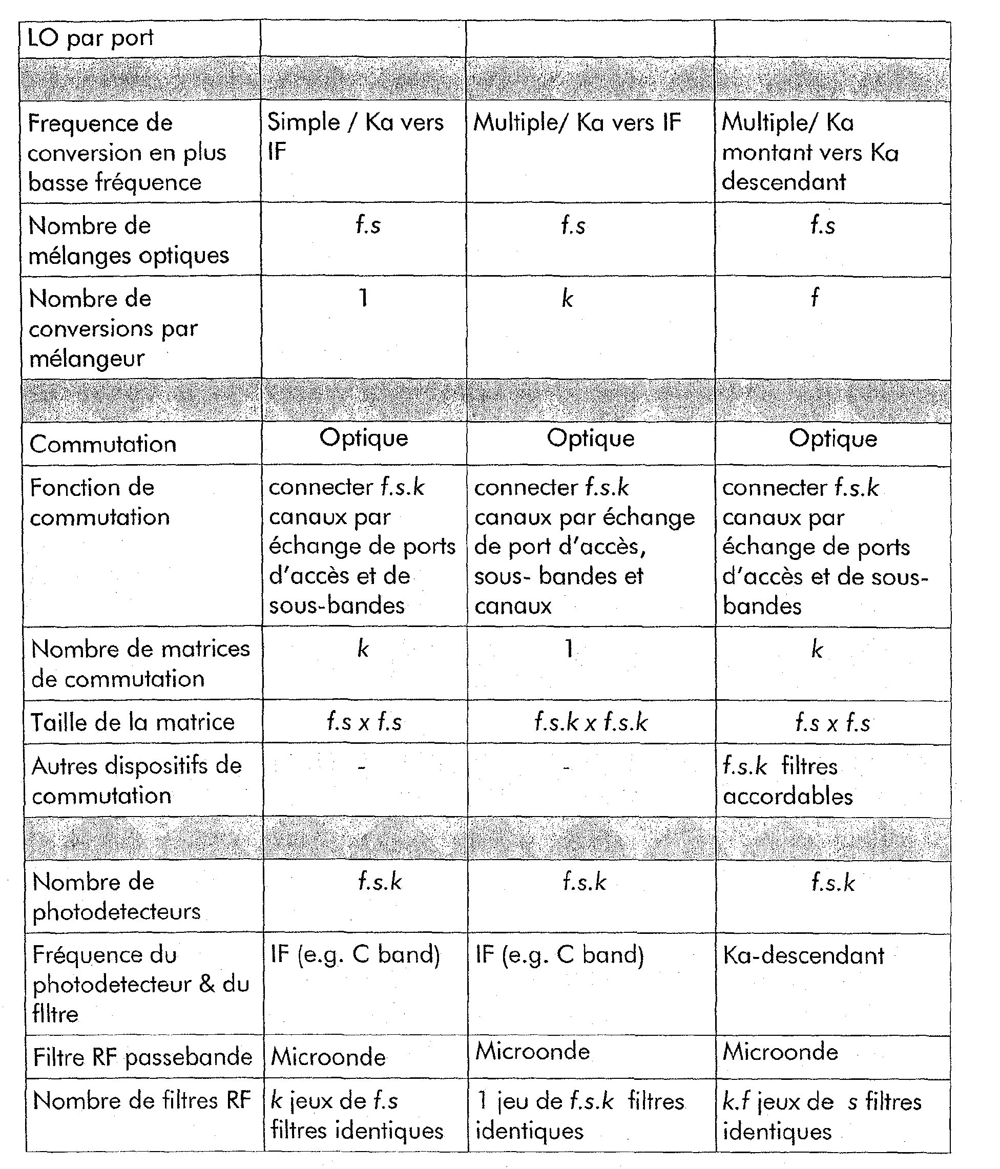
- the optical output fiber of the optical modulator 5 conveys the intermediate frequency microwave signals on wavelengths which are amplified through an appropriate optical amplifier 7, then demultiplexed according to optical fibers thanks to a demultiplexer 19 and finally distributed on the input ports of the matrix 11 optical switching (switching and interconnection unit). If there are k channels per subband frequency, and fs access amounts, the size of the square matrix is f.s.k x f.s.k.
- the matrix connects the input signals to f.s.k receivers IF-band optoelectronic devices that interface bandpass filters of channels.
- the filters which are f.s.k and are identical, are set implemented at the IF frequency, typically in the C or S bands.
- any frequency channel can be rendered available at the output of any filter.
- This repeater architecture to multiple beams is able to interconnect RF channels by exchanging accesses and subbands, and also exchanging channels.
- band C (approximately 3 to 5 GHz) is adopted as intermediate frequency
- the LO frequencies generated by unit 6 shall be 25-27 GHz (because the frequency at the repeater input is around 30 GHz).
- f groups of k different LO frequencies must be generated, each distributed to s converters in lower frequency (optical modulator 5).
- the total number of interconnected channels is f.s.k.
- the multiple beam repeater of the architecture of Figure 6 supports on the full connectivity switching function, which is schematically in Figure 7.
- the switching unit (switching matrix) can be seen as a single switch with total connectivity that is reconfigurable in a strictly non-blocking mode.
- Any given input channel, entering from an access port amount can be routed to any output channel of an access port descending.
- such a repeater architecture is capable to interconnect RF channels by totally exchanging accesses, subbands and channels.
- Ka-IF-Ka Double conversion repeater
- FIG. 8 represents a variant of architecture of a repeater to reconfigurable multiple beams with only a single stage of frequency conversion.
- the architecture incorporates, as above, optical technologies for the distribution and mixing of signals of local oscillators and for the interconnection of microwave signals to the Ka frequency downlink.
- the mixture of frequencies on the lower frequency converter is achieved through the modulators
- the required local oscillators are generated at the level of the generation of local oscillators 6 and are optically distributed on the optical frequency converters.
- the wavelength division multiplexing (WDM) principle is used to power the lower optical frequency converter with more than one LO signal so as to simultaneously perform transpositions. multiple frequencies. These LO signals are chosen to have several frequencies, all equally spaced by the spacing between frequency subbands. If there are af frequency sub-bands separated by ⁇ , the following set of (2.f-1) LO frequencies is generated: ⁇ LO - (f-1) ⁇ , ..., ⁇ LO - ⁇ , ⁇ LO , ⁇ LO + ⁇ , ..., ⁇ LO + (F-1) ⁇
- All the LO signals gathered within the same group are combined on the same optical fiber thanks to a distribution multiplexer in wavelength 18 and distributed to the optical modulators connected to receiving channels using the same frequency sub-band.
- Each of these frequencies is carried at a different wavelength in the output optical fiber of modulator 5.
- the modulator output fiber carries these microwave signals at intermediate frequencies over optical wavelengths, which are amplified through an appropriate optical amplifier, and divided into power over k optical fibers and then distributed on the input ports of k optical switching matrices 11 1 , ..., 11 k .
- the switching matrices have, at their input, tunable optical filters 20 (referenced in FIG. 8, TF for "Tunable Filter”) which are intended to select any one of the f channels of wavelength.
- each matrix connects the input signals to photoelectric detectors bandwidth of the downlink frequency, these receivers interfacing the channel band pass filters.
- a bank of k filters 13 replaces the input multiplexer.
- Each output port has a bank of k filters 13. At total, there are k.f identical sets of filters. These filters must be implemented at the downlink frequency, typically in the 18-21 band GHz.
- the set of switching matrices 11 1 ,..., 11 k acts as k switching planes in parallel, each managing and interconnecting frequency channels occupying the same rank in the channel multiplex.
- the tunable optical filter 20 is here to select the wavelength carrying the microwave signal.
- any given input channel entering through an access port amount can be routed to any outgoing channel of the same rank and on any downstream access port.
- This repeater architecture to multiple beams is able to interconnect RF channels by exchanging accesses and subbands, but without exchanging channels.
- the frequencies of the LO signals are in the range [7-13 GHz].
- the main advantage of this architecture is that it allows for interconnection flexible with only one frequency conversion stage.
- the disadvantage lies in the fact that bandpass filters working on the frequency range of the downlink Ka, namely 18-21 GHz, where high selectivity is not easily achieved.
- Fig. 9 shows a variant of the embodiments with additional means to extract some of the channels amounts and direct them to a digital processor 30 for functions of filtering and routing with finer resolution.
- the unit 6 In addition to the LO signals already presented, the unit 6 generates in this variant an optical sampling signal on a wavelength additional.
- This sampling signal consists of a continuous flow of very short optical pulses (of duration of the order of one picosecond) with a repetition frequency at least equal to or greater than the width of band of uplink microwave signals.
- the optical sampling signal can be delivered to one any of the optical modulators instead of or in addition to the lengths of waves that carry the LO signals.
- the flow of optical samples available at the output of the optical modulator is directed to the processor digital.
- the processor has inputs equipped with photo-detectors and other suitable means known to those skilled in the art to adapt the optical samples to analog-to-digital converters, and has outputs equipped with optical sources.
- the processor can perform sub-channel routing and other fine processing. This variant can be applied to any of the previous embodiment.
- the invention is of course applicable to frequency bands other than those given for illustrative purposes.
- the invention can be extended to devices where the frequencies sub-bands or frequency channels ( frequency) are not regularly spaced, as described previously.
- the frequencies of the local oscillators take values which, themselves, are not evenly spaced and it can be necessary to generate a larger number of local oscillators.
- the invention can be extended to devices having a number access port different from the number of input ports, to devices with a number of subbands per output port different from number of subbands per entry access, as well as with a number of channels per output sub-band different from the number of channels per input subbands.
- This can lead in particular to use non-square matrices or sub-matrices, including a number of output ports different from the number of input ports.
- the invention can be extended to devices having a number different channels per subband according to the accesses, in input as in exit.
Landscapes
- Engineering & Computer Science (AREA)
- Computer Networks & Wireless Communication (AREA)
- Signal Processing (AREA)
- Physics & Mathematics (AREA)
- Astronomy & Astrophysics (AREA)
- General Physics & Mathematics (AREA)
- Electromagnetism (AREA)
- Optical Communication System (AREA)
Abstract
Description
- une unité de génération et de distribution de signaux optiques d'oscillateurs locaux,
- un ensemble de N modulateurs optiques d'intensité aptes à être
alimentés respectivement d'une part par un des N signaux micro-ondes
multiplex d'entrée et d'autre part par au moins un parmi une pluralité de
signaux optiques d'oscillateurs locaux de l'unité, chaque modulateur étant
alors utilisé comme mélangeur optique pour délivrer en sortie un signal
optique de sortie du modulateur qui véhicule au moins une composante
fréquentielle dite à fréquence intermédiaire sur une porteuse optique,
et étant entendu que chaque sous-bande de fréquence comporte k canaux ordonnés de 1 à k, - des moyens de commutation et d'aiguillage comportant N.k entrées pour recevoir respectivement les canaux desdits signaux de sortie du modulateur et les aiguiller selon une configuration donnée respectivement vers des premiers photo-détecteurs aptes à délivrer N.k signaux radiofréquence intermédiaires de sortie,
- lesdits N signaux radiofréquence intermédiaires de sortie étant traités par des moyens de traitement de manière à fournir N signaux radiofréquence muliplex délivrables à ladite au moins une antenne d'émission.
- les modulateurs optiques d'intensité sont utilisés comme mélangeurs optiques pour réaliser des transpositions de fréquences RF ("down-conversion" en anglais).
- le multiplexage en longueur d'onde est largement mis à profit pour transporter plusieurs signaux sur le même support (une fibre par exemple), ou encore mélanger un signal avec plusieurs signaux optiques d'oscillateurs locaux simultanément sans pour autant créer d'interférences.
- la figure 1 représente un répéteur de télécommunications selon un mode de réalisation de l'invention,
- la figure 2 illustre un mélange optique pour une conversion multiple en plus basses fréquences,
- la figure 3 représente le principe de réutilisation de fréquences,
- la figure 4 représente un répéteur de télécommunications selon une variante de l'invention,
- la figure 5 illustre le schéma de commutation des ports d'accès et des sous-bandes de fréquence,
- la figure 6 représente un répéteur de télécommunications selon une seconde variante de l'invention,
- la figure 7 illustre le schéma de commutation des ports d'accès, des sous-bandes de fréquence et des canaux de fréquence,
- la figure 8 représente un répéteur de télécommunications selon une troisième variante de l'invention,
- le nombre f de sous-bandes de fréquence est égal à 4, chaque sous bande ayant une bande de 250 MHz,
- le nombre k de canaux de fréquenceest égal à 3 (soit une bande par canal de 72 MHz environ), ou égal à 6 (soit une bande par canal de 36 MHz environ)
- le nombre de faisceaux, f.s pris par exemple égal à 24 (s étant alors égal à 6),
- le nombre total de canaux, f.s.k est alors de 72 x 72 MHz, respectivement de 144 x 36 MHz.
- 1er groupe : ωLO-(f-1)Δω, ..., ωLO-Δω, ωLO
- 2ème groupe : ωLO-(f-2)Δω, ..., ωLO-Δω, ωLO, ωLO+Δω
- fième groupe : ωLO, ωLO+Δω,..., ωLO+(f-1)Δω

Claims (10)
- Dispositif de brassage spatio-fréquentiel de signaux pour un répéteur de télécommunications d'un véhicule spatial de télécommunications, comportant une première pluralité d'entrées (#1, ..., #f.s) apte à recevoir respectivement N signaux micro-ondes multiplex d'entrée provenant d'au moins une antenne de réception, une seconde pluralité de sorties (#1, ..., #f.s) apte à délivrer respectivement N signaux micro-ondes multiplex de sortie vers au moins une antenne d'émission, caractérisé en ce que ledit dispositif (11) comporte :une unité (6) de génération et de distribution de signaux optiques d'oscillateurs locaux (LO, 8),un ensemble de N modulateurs optiques (OM, 5) d'intensité aptes à être alimentés respectivement d'une part par un des N signaux micro-ondes multiplex d'entrée et d'autre part par au moins un parmi une pluralité de signaux optiques d'oscillateurs locaux de l'unité (6), chaque modulateur étant alors utilisé comme mélangeur optique pour délivrer en sortie un signal optique de sortie du modulateur qui véhicule au moins une composante fréquentielle dite à fréquence intermédiaire (fRF - fOL) sur au moins une porteuse optique,
et étant entendu que chaque sous-bande de fréquence comporte k canaux ordonnés de 1 à k,des moyens de commutation et d'aiguillage (11, 11l,...,11k) comportant N.k entrées pour recevoir respectivement les canaux desdits signaux de sortie du modulateur et les aiguiller selon une configuration donnée respectivement vers des premiers photo-détecteurs (12) aptes à délivrer N.k signaux radiofréquence intermédiaires de sortie,lesdits N signaux radiofréquence intermédiaires de sortie étant traités par des moyens de traitement (8', 9', 13, 14, 12',15, 16, 17) de manière à fournir N signaux radiofréquence muliplex délivrables à ladite au moins une antenne d'émission. - Dispositif selon la revendication 1, caractérisé en ce que, les antennes de réception et d'émission fonctionnant selon le principe de réutilisation de fréquences, f étant le nombre de sous-bandes de fréquences et s étant le facteur de réutilisation de ces sous bandes de fréquences, N étant alors égal à f.s, l'unité (6) comprend une première série de f générateurs (8) de signaux d'oscillateurs locaux suivis respectivement d'un émetteur (9) optoélectronique, chacun de ces derniers délivrant son signal aux s modulateurs optiques reliés à la voie de réception utilisant la même sous-bande de fréquence.
- Dispositif selon la revendication 2, caractérisé en ce que, chaque sous-bande de fréquence comportant k canaux ordonnés de 1 à k, un canal étant une tranche fréquentiel, chaque modulateur optique est relié en sortie à un amplificateur optique (7') et un coupleur (7") apte à diviser en puissance le signal optique de sortie du modulateur pour le délivrer aux moyens de commutation constitués de k sous-matrices carrées (11l, ..., 11k) de taille f.s x f.s, chaque sous-matrice traitant les canaux d'un rang qui lui est propre et redistribuant lesdits canaux sur f.s.k voies d'émission.
- Dispositif selon la revendication 3, caractérisé en ce que les canaux sont regroupés, en sortie des moyens de commutation, par groupes de k voies d'émission pour former f.s signaux multiplex de manière à ce que chaque canal conserve le rang qui lui était conféré dans le signal multiplex d'entrée d'origine.
- Dispositif selon la revendication 4, caractérisé en ce que l'unité (6) comprend également une seconde série de f générateurs de signaux d'oscillateurs locaux (8') couplés à leur photodétecteur (9') propre, chacun d'eux délivrant son signal aux mélangeurs (14) respectifs de s groupes de k voies d'émission destinés à utiliser la même sous-bande de fréquence d'émission, de manière à faire subir sur chacune des voies d'émission une conversion en plus hautes fréquences.
- Dispositif selon l'une des revendications 2 à 5, caractérisé en ce que, les N signaux micro-ondes multiplex d'entrée comportant chacun k canaux de fréquence espacé de Δω, entre chacun des f générateurs (8) de signaux d'oscillateurs locaux de fréquence propre ωLO de ladite première série suivis de leur propre émetteur (9) optoélectronique et leurs s modulateurs optiques correspondants se trouve un multiplexeur (18) de longueurs d'ondes, ce dernier multiplexant la sortie de chacun desdits émetteurs (9) optoélectroniques reliés aux générateurs (8) respectifs de fréquence propre ωLO avec la sortie de k-1 émetteurs (9) optoélectroniquesreliés à k-1 générateurs de signaux d'oscillateurs locaux dont les fréquences respectives sont ωLO+Δω,..., ωLO+(k-1) Δω, ledit couplage assurant la translation de fréquences multiples des k canaux sur les voies d'entrée.
- Dispositif selon la revendication 2, caractérisé en ce que l'unité (6) comporte 2f-1 générateurs de signaux d'oscillateurs locaux LO et en en ce que f groupes de signaux LO sont formés de manière non exclusive et glissante pour permettre, pour chacun des groupes, la génération, après multiplexage, de f signaux LO successifs, les 2f-1 signaux LO d'origine étant : ωLO-(f- 1)Δω, ..., ωLO-Δω, ωLO, ω LO+Δω,..., ωLO+(f-1)Δω,
et en ce que deux groupes consécutifs de rang i et i+1 partagent le signal LO de fréquence la plus basse du second groupe i+1 1 de la manière suivante :1er groupe : ωLO-(f-1)Δω, ..., ωLO-Δω, ωLO2ème groupe : ωLO-(f-2)Δω, ..., ωLO-Δω, ωLO, ωLO+Δωfième groupe : ωLO,ωLO+Δω,..., ωLO+(f-1)Δω - Dispositif selon l'une des revendications 1 à 7, caractérisé en ce que l'unité (6) comporte des moyens de génération d'un signal d'échantillonnage optique porté par une longueur d'onde supplémentaire en sortie d'un modulateur (5), cette dernière longueur d'onde permettant d'extraire et d'aiguiller une partie des canaux vers un équipement de sortie, ceci grâce à un processeur numérique exerçant une fonction de filtrage et de routage avec une résolution plus fine.
- Répéteur de télécommunications, caractérisé en ce qu'il comporte un dispositif selon l'une des revendications 1 à 6.
- Satellite de télécommunications, caractérisé en ce qu'il comporte un répéteur selon la revendication 9.
Applications Claiming Priority (2)
| Application Number | Priority Date | Filing Date | Title |
|---|---|---|---|
| FR0314983A FR2864385B1 (fr) | 2003-12-19 | 2003-12-19 | Dispositif de brassage spatio-frequentiel de signaux pour repeteur de telecommunications d'un satellite, repeteur et satellite associes |
| FR0314983 | 2003-12-19 |
Publications (2)
| Publication Number | Publication Date |
|---|---|
| EP1545035A1 true EP1545035A1 (fr) | 2005-06-22 |
| EP1545035B1 EP1545035B1 (fr) | 2009-09-02 |
Family
ID=34508711
Family Applications (1)
| Application Number | Title | Priority Date | Filing Date |
|---|---|---|---|
| EP20040292593 Expired - Lifetime EP1545035B1 (fr) | 2003-12-19 | 2004-11-02 | Dispositif de brassage spatio-fréquentiel de signaux pour répéteur de télécommunications d'un satellite, répéteur et satellite associés |
Country Status (3)
| Country | Link |
|---|---|
| EP (1) | EP1545035B1 (fr) |
| DE (1) | DE602004022911D1 (fr) |
| FR (1) | FR2864385B1 (fr) |
Cited By (2)
| Publication number | Priority date | Publication date | Assignee | Title |
|---|---|---|---|---|
| RU2420760C2 (ru) * | 2009-11-26 | 2011-06-10 | Открытое акционерное общество "Российская корпорация ракетно-космического приборостроения и информационных систем" (ОАО "Российские космические системы") | Способ оценки эффективности радиоподавления сигнала спутниковой связи путем воздействия помехами на приемные системы ретрансляторов и устройство для его реализации |
| WO2017031227A1 (fr) | 2015-08-18 | 2017-02-23 | Lockheed Martin Corporation | Récepteur photonique multicanaux intégré |
Families Citing this family (3)
| Publication number | Priority date | Publication date | Assignee | Title |
|---|---|---|---|---|
| FR3043514B1 (fr) * | 2015-11-06 | 2018-10-19 | Thales | Dispositif photonique de brassage et de conversion frequentielle de signaux a radiofrequence et charge utile de telecommunications spatioportee comprenant un tel dispositif |
| FR3078598B1 (fr) * | 2018-03-01 | 2020-02-07 | Thales | Dispositif et procede photonique de conversion de frequence a double bande |
| FR3155394B1 (fr) | 2023-11-09 | 2026-04-17 | Thales Sa | Dispositif photonique et procédé de transmission et/ou de conversion en fréquence de signaux radiofréquence d'un satellite de télécommunications |
Citations (1)
| Publication number | Priority date | Publication date | Assignee | Title |
|---|---|---|---|---|
| EP1017242A1 (fr) * | 1998-12-28 | 2000-07-05 | Italtel s.p.a. | Architecture d' interconnexion optique pour des systèmes de télécommunication MRL (WDM) |
-
2003
- 2003-12-19 FR FR0314983A patent/FR2864385B1/fr not_active Expired - Fee Related
-
2004
- 2004-11-02 EP EP20040292593 patent/EP1545035B1/fr not_active Expired - Lifetime
- 2004-11-02 DE DE200460022911 patent/DE602004022911D1/de not_active Expired - Lifetime
Patent Citations (1)
| Publication number | Priority date | Publication date | Assignee | Title |
|---|---|---|---|---|
| EP1017242A1 (fr) * | 1998-12-28 | 2000-07-05 | Italtel s.p.a. | Architecture d' interconnexion optique pour des systèmes de télécommunication MRL (WDM) |
Non-Patent Citations (2)
| Title |
|---|
| HUSBANDS, C.R. ; DEVINE, J.F.: "Wideband analog signal transmission in all-optical networks", CHAOTIC CIRCUITS FOR COMMUNICATION, vol. 2612, 23 October 1995 (1995-10-23) - 24 October 1995 (1995-10-24), PHILADELPHIA, PENNSYLVANIA, USA, pages 115 - 124, XP008032748 * |
| SHIEH W ET AL: "MICROWAVE SIGNAL MIXING BY USING A FIBER-BASED OPTOELECTRONIC OSCILLATOR FOR WAVELENGTH-DIVISION MULTIPLEXED SYSTEMS", CONFERENCE ON OPTICAL FIBER COMMUNICATIONS. DALLAS, FEB. 16 - 21, 1997, NEW YORK, IEEE, US, 16 February 1997 (1997-02-16), pages 358 - 359, XP009006333, ISBN: 0-7803-3860-X * |
Cited By (3)
| Publication number | Priority date | Publication date | Assignee | Title |
|---|---|---|---|---|
| RU2420760C2 (ru) * | 2009-11-26 | 2011-06-10 | Открытое акционерное общество "Российская корпорация ракетно-космического приборостроения и информационных систем" (ОАО "Российские космические системы") | Способ оценки эффективности радиоподавления сигнала спутниковой связи путем воздействия помехами на приемные системы ретрансляторов и устройство для его реализации |
| WO2017031227A1 (fr) | 2015-08-18 | 2017-02-23 | Lockheed Martin Corporation | Récepteur photonique multicanaux intégré |
| EP3338380A4 (fr) * | 2015-08-18 | 2019-04-24 | Lockheed Martin Corporation | Récepteur photonique multicanaux intégré |
Also Published As
| Publication number | Publication date |
|---|---|
| EP1545035B1 (fr) | 2009-09-02 |
| DE602004022911D1 (de) | 2009-10-15 |
| FR2864385B1 (fr) | 2006-03-03 |
| FR2864385A1 (fr) | 2005-06-24 |
Similar Documents
| Publication | Publication Date | Title |
|---|---|---|
| EP3223441B1 (fr) | Satellite de communication à grande capacité utilisant une formation de faisceau optique passive | |
| EP0584012B1 (fr) | Dispositif de commutation transparente, notamment pour le domaine spatial et charge utile utilisant un tel dispositif | |
| US8861967B2 (en) | Reconfigurable optical add/drop multiplexer and reconfigurable optical add/drop multiplexing method | |
| EP3166233B1 (fr) | Dispositif photonique de brassage et de conversion frequentielle de signaux a radiofrequence et charge utile de telecommunications spatioportee comprenant un tel dispositif | |
| US10250330B1 (en) | Flexible signal distribution assisted by tunable optical carrier modulating a desired signal | |
| FR2686203A1 (fr) | Systeme de distribution optique de telecommunications. | |
| US10069565B2 (en) | Satellite system using optical gateways and onboard processing | |
| FR2648295A1 (fr) | Aiguilleur a largeur de bande et frequence centrale variables pour satellites multifaisceaux | |
| EP0549451A1 (fr) | Dispositif de démultiplexage en fréquence à filtres numériques | |
| EP1346499A2 (fr) | Systeme et procede permettant d'augmenter la capacite d'un canal de reseau de communications a fibre optique | |
| EP2723001B1 (fr) | Système de télécommunications par satellite à grande capacité à couverture multifaisceaux et à réutilisation de fréquence | |
| EP2337238B1 (fr) | Système d'émission et de réception multi-spots à bord d'un satellite | |
| Aveline et al. | Reconfigurable microwave photonic repeater for broadband telecom missions: concepts and technologies | |
| Edwards | Gigahertz and terahertz technologies for broadband communications | |
| EP3332493A1 (fr) | Réception de signaux optiques multi-longueurs d'onde composés de rafales optiques mono-bandes | |
| EP1545035B1 (fr) | Dispositif de brassage spatio-fréquentiel de signaux pour répéteur de télécommunications d'un satellite, répéteur et satellite associés | |
| JP4776835B2 (ja) | 光ファイバネットワークシステムの伝送方式 | |
| EP1499013B1 (fr) | Dispositif d'amplification pour satellite | |
| EP3794747A1 (fr) | Procede de gestion du trafic de donnees de telecommunication d'un systeme de communication a tres haut debit par satellites | |
| US8909046B2 (en) | Switching and routing protocol for a fiber optic transmission system | |
| EP4078855B1 (fr) | Infrastructure de transport de données radiofréquences par fibre optique | |
| FR3062267A1 (fr) | Architecture de charge utile d’un satellite de telecommunications | |
| EP1717980A1 (fr) | Dispositif de commutation optique modulaire et reconfigurable | |
| FR3052940A1 (fr) | ||
| FR3054090A1 (fr) | Systeme de satellite qui produit un faisceau de liaison intersatellite (isl) optique sur la base d'un faisceau de liaison montante de ligne d'alimentation optique |
Legal Events
| Date | Code | Title | Description |
|---|---|---|---|
| PUAI | Public reference made under article 153(3) epc to a published international application that has entered the european phase |
Free format text: ORIGINAL CODE: 0009012 |
|
| AK | Designated contracting states |
Kind code of ref document: A1 Designated state(s): AT BE BG CH CY CZ DE DK EE ES FI FR GB GR HU IE IS IT LI LU MC NL PL PT RO SE SI SK TR |
|
| AX | Request for extension of the european patent |
Extension state: AL HR LT LV MK YU |
|
| 17P | Request for examination filed |
Effective date: 20051214 |
|
| AKX | Designation fees paid |
Designated state(s): DE FR |
|
| RAP1 | Party data changed (applicant data changed or rights of an application transferred) |
Owner name: ALCATEL LUCENT |
|
| 17Q | First examination report despatched |
Effective date: 20071008 |
|
| GRAP | Despatch of communication of intention to grant a patent |
Free format text: ORIGINAL CODE: EPIDOSNIGR1 |
|
| GRAS | Grant fee paid |
Free format text: ORIGINAL CODE: EPIDOSNIGR3 |
|
| GRAC | Information related to communication of intention to grant a patent modified |
Free format text: ORIGINAL CODE: EPIDOSCIGR1 |
|
| RAP1 | Party data changed (applicant data changed or rights of an application transferred) |
Owner name: THALES |
|
| GRAA | (expected) grant |
Free format text: ORIGINAL CODE: 0009210 |
|
| AK | Designated contracting states |
Kind code of ref document: B1 Designated state(s): DE FR |
|
| REF | Corresponds to: |
Ref document number: 602004022911 Country of ref document: DE Date of ref document: 20091015 Kind code of ref document: P |
|
| PLBE | No opposition filed within time limit |
Free format text: ORIGINAL CODE: 0009261 |
|
| STAA | Information on the status of an ep patent application or granted ep patent |
Free format text: STATUS: NO OPPOSITION FILED WITHIN TIME LIMIT |
|
| 26N | No opposition filed |
Effective date: 20100603 |
|
| REG | Reference to a national code |
Ref country code: FR Ref legal event code: PLFP Year of fee payment: 12 |
|
| REG | Reference to a national code |
Ref country code: FR Ref legal event code: PLFP Year of fee payment: 13 |
|
| REG | Reference to a national code |
Ref country code: FR Ref legal event code: PLFP Year of fee payment: 14 |
|
| REG | Reference to a national code |
Ref country code: FR Ref legal event code: PLFP Year of fee payment: 15 |
|
| PGFP | Annual fee paid to national office [announced via postgrant information from national office to epo] |
Ref country code: FR Payment date: 20231024 Year of fee payment: 20 Ref country code: DE Payment date: 20231017 Year of fee payment: 20 |
|
| REG | Reference to a national code |
Ref country code: DE Ref legal event code: R071 Ref document number: 602004022911 Country of ref document: DE |