EP1544999A2 - Method for determining a tuning frequency of an audio receiver - Google Patents
Method for determining a tuning frequency of an audio receiver Download PDFInfo
- Publication number
- EP1544999A2 EP1544999A2 EP04078391A EP04078391A EP1544999A2 EP 1544999 A2 EP1544999 A2 EP 1544999A2 EP 04078391 A EP04078391 A EP 04078391A EP 04078391 A EP04078391 A EP 04078391A EP 1544999 A2 EP1544999 A2 EP 1544999A2
- Authority
- EP
- European Patent Office
- Prior art keywords
- audio
- audio signal
- receiver
- modulated
- output
- Prior art date
- Legal status (The legal status is an assumption and is not a legal conclusion. Google has not performed a legal analysis and makes no representation as to the accuracy of the status listed.)
- Withdrawn
Links
Images


Classifications
-
- H—ELECTRICITY
- H03—ELECTRONIC CIRCUITRY
- H03J—TUNING RESONANT CIRCUITS; SELECTING RESONANT CIRCUITS
- H03J1/00—Details of adjusting, driving, indicating, or mechanical control arrangements for resonant circuits in general
- H03J1/0008—Details of adjusting, driving, indicating, or mechanical control arrangements for resonant circuits in general using a central processing unit, e.g. a microprocessor
-
- H—ELECTRICITY
- H03—ELECTRONIC CIRCUITRY
- H03J—TUNING RESONANT CIRCUITS; SELECTING RESONANT CIRCUITS
- H03J2200/00—Indexing scheme relating to tuning resonant circuits and selecting resonant circuits
- H03J2200/28—Automatic self-alignment of a receiver
Definitions
- the present invention is generally directed to an audio receiver and, more specifically, determining a tuning frequency of an audio receiver.
- RF radio frequency
- FM frequency modulation
- CD compact disc
- LO local oscillator
- What is needed is a device that, when placed between a radio frequency (RF) receiver and its associated antenna, determines a current channel of the receiver.
- RF radio frequency
- One embodiment of the present invention is directed to a technique for determining a tuning frequency of an audio receiver. Initially, a received radio frequency (RF) signal at an input of an audio receiver is interrupted. Next, a modulated audio signal is injected into the input of the audio receiver. Then, it is determined whether a demodulated audio signal that corresponds to the modulated audio signal is present at the output of the audio receiver. If not, the frequency of the modulated audio signal is changed until the demodulated audio signal is detected at the output of the audio receiver.
- RF radio frequency
- the modulated audio signal may be initially injected at a last known channel of the audio receiver.
- the modulated audio signal is one of a tone, a sequence of tones, a set of tones and a pseudo random noise (PRN).
- PRN pseudo random noise
- the received RF signals are interrupted responsive to an audio source.
- the modulated audio signal is one of an amplitude modulator (AM) signal and a frequency modulated (FM) signal.
- audio content from an audio source is provided at the output of the audio receiver when the demodulated audio signal is present at the output of the audio receiver, thus, indicating that the modulated audio signal is tuned to the current channel of the audio receiver.
- a modulated audio signal is superimposed on a received radio frequency (RF) signal at an input of an audio receiver.
- RF radio frequency
- an audio subsystem is implemented that injects an audio signal between a radio frequency receiver and its associated antenna.
- the subsystem interrupts a received RF signal and injects an audio signal at the last known frequency, which statistically speeds up tuning, or may step through a sequence of frequencies.
- the subsystem looks for the expected audio signal at the output of the audio receiver, e.g., at the speakers of the audio system. If the expected audio signal is not present at the output of the audio receiver, the system changes to the next frequency and repeats until the correct frequency is found.
- the subsystem may use a microphone (or other device) to detect the audio signal at the output of the audio receiver.
- the known audio signal may be a tone, a sequence of tones, a set of tones, a pseudo random noise (PRN) or other detectable input.
- PRN pseudo random noise
- an audio subsystem continually monitors and tracks a current radio frequency (RF) channel and superimposes an audio signal on top of received RF signals.
- the superimposed audio signal is low in power, as compared to the received RF signal currently on the channel, such that a listener does not detect the intrusion but the audio signal is detectable at the output of the audio receiver.
- a known pseudo random noise (PRN) may be superimposed that is unnoticeable to a user, but detectable. For example, if the PRN sequence is long enough, the superimposed signal may readily be detectable.
- the subsystem may, in general, step through a series of channels until the audio signal is detected at the output of the audio receiver.
- an exemplary audio system 100 includes a processor 102 that is coupled to a memory subsystem 104, a display 120, an AM/FM tuner 124 and a plurality of audio sources 130.
- the processor 102 controls audio content provided to a listener, via the speaker 112, and may also supply various information to a user, via the display 120 and/or the speaker 112.
- the term processor may include a general purpose processor, a microcontroller (i.e., an execution unit with memory, etc., integrated within a single integrated circuit), an application specific integrated circuit (ASIC), a programmable logic device (PLD) or a digital signal processor (DSP).
- the memory subsystem 104 includes an application appropriate amount of memory (e.g., volatile and non-volatile memory), which provides storage for various routines that are used to tune the tuner 124 and may also provide a storage area for one or more speech recognition applications.
- an audio input device 118 e.g., a microphone
- the filter/amplifier module 116 filters and amplifies the voice input provided by a user through the audio input device 118.
- the filter/amplifier module 116 is also coupled to an analog-to-digital (A/D) converter 114, which digitizes the voice input from the user and supplies the digitized voice to the processor 102 which may execute a speech recognition application, which causes the voice input to be compared to system recognized commands.
- A/D converter 114 analog-to-digital converter 114
- the audio input device 118, the filter/amplifier module 116 and the A/D converter 114 form a voice input circuit 119.
- the processor 102 may execute various routines in determining whether the voice input corresponds to a system recognized command and/or a specific operator.
- the processor 102 may also cause an appropriate voice output to be provided to the user through an audio output device 112.
- the synthesized voice output is provided by the processor 102 to a digital-to-analog (D/A) converter 108.
- the D/A converter 108 is coupled to a filter/amplifier section 110, which amplifies and filters the analog voice output.
- the amplified and filtered voice output is then provided to audio output device 112 (e.g., a speaker).
- the processor 102 is also coupled to a global position system (GPS) receiver 140, which allows the system 100 to determine the location of the receiver 140 and its associated motor vehicle.
- GPS global position system
- An audio subsystem 150 allows various after-market devices, e.g., mobile phones, satellite digital audio radio systems (SDARS) and compact disc (CD) players, to utilize the audio system 100 installed within a motor vehicle.
- an antenna 125 associated with the motor vehicle, is coupled to a switch/coupler 151, whose output is coupled to an input of the tuner 124.
- the switch/coupler 151 may be implemented as either a switch or a coupler and, as discussed further below, the modulated audio output provided from the modulator 162 replaces the RF signal received by the antenna 125 when the switch/coupler 151 is a switch.
- the switch/coupler 151 When the switch/coupler 151 is a coupler, the modulated audio output provided from the modulator 162 is superimposed on the signal received via the antenna 125. It should be appreciated that, in either case, the signal provided through the modulator 162 is only provided at the output of the audio system 100 when the signal provided from the modulator 162 is modulated at a frequency that corresponds to the current channel of the tuner 124.
- the subsystem 150 also includes a processor 152 that is coupled to a detector 154, the modulator 162, a multiplexer 160, an audio signal generator 156 and an external audio source 158.
- the switch/coupler 151 When the switch/coupler 151 is implemented as a switch, the processor 152 controls whether the output from the antenna 125 or the modulator 162 is provided to the input of the tuner 124.
- the switch/coupler 151 When the switch/coupler 151 is implemented as a coupler, a separate control line is not required (from the processor 152 to the coupler) as the signal provided by the modulator 162 is superimposed on the RF signal received via the antenna 125.
- the detector (e.g., a microphone) 154 is coupled to the processor 152 and provides an indication to the processor 152 whether a signal provided via the modulator 162 is present at the output, i.e., at the speaker 112, of the audio system 100. If the signal is not detected via the detector 154, the processor 152 controls the modulator 162 to step to a next frequency or next channel. The processor 152 controls the multiplexer 160 to provide either a signal from an audio signal generator 156 or the external audio source 158.
- the signal from the audio signal generator 156 may take various forms, such as a tone, a sequence of tones, a set of tones or a pseudo random noise (PRN), which is utilized by the processor 152 to determine whether the modulator 162 is tuned to an appropriate frequency.
- PRN pseudo random noise
- the processor 152 controls the multiplexer 160 to select an audio signal from the audio source 158.
- the output from the audio source 158 is then modulated by the modulator 162 before being provided to an input of the tuner 124, via the switch/coupler 151, and ultimately to a listener, via the speaker 112.
- the processor 152 causes the received radio frequency (RF) signal at the input of the audio receiver (i.e., the tuner 124) to be interrupted and injects a modulated audio signal provided by the audio signal generator 156 at the input of the audio receiver (tuner 124).
- the processor 152 changes the frequency of the modulated audio signal provided by the audio signal generator 156.
- the modulated audio signal is initially provided at a last known radio frequency channel.
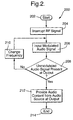
- a routine 200 is illustrated, which is implemented by the processor 152 in determining a tuning frequency of the tuner 124.
- the routine 200 is initiated, at which point control transfers to step 204, where the processor 152 causes the RF signal received via the antenna 125 to be interrupted by controlling the switch within the switch/coupler 151.
- the processor 152 by controlling the modulator 162, the multiplexer 160 and the audio signal generator 156, causes an injected modulated audio signal to be provided to an input of the tuner 124.
- the processor 152 determines whether a demodulated audio signal that corresponds to the modulated audio signal is present at the output of the tuner 124, e.g., at the speaker 112.
- the processor 152 determines whether the demodulated audio signal is present at the output of the tuner 124 by examining a signal received by the detector 154. When the processor 152 determines that the demodulated audio signal is present at the output of the tuner 124, the processor 152 causes the multiplexer 160 to switch to provide audio content from the audio source 158 in step 212. However, when the demodulated audio signal is not present at the output of the tuner 124 in step 208, the processor 152 causes the modulator 162 to change frequency in step 210, at which point control is transferred to step 206. In step 208, when the demodulated audio signal is present at the output of the tuner 124, control transfers to step 212 where audio content is provided from the audio source 158, before terminating the routine 200 in step 214.
- the processor 152 implements a routine 300, which is initiated in step 302.
- the processor 152 controls the modulator 162 to cause a modulated audio signal (provided by the audio signal generator 156 via the multiplexer 160) to be superimposed on the RF signal received via the antenna 125.
- the processor 152 determines whether a demodulated audio signal that corresponds to the modulated audio signal is present at the output of the tuner 124. As is discussed above, the processor 152 determines whether the audio signal is present at the output of the tuner 124 by examining an output signal provided by the detector 154.
- step 306 when the processor 152 does not detect the demodulated audio signal at the output of the audio system 100, control transfers to step 308.
- step 308 the processor 152 controls the modulator 162 to change the modulation frequency, at which point control transfers to step 304.
- decision step 306 when the demodulated audio signal is present at the output of the tuner 124, control transfers to step 310 and the processor 152 controls the multiplexer 160 to couple the output from the audio source 158 to the modulator 162, which is then provided via a coupler (associated with the switch/coupler 151) to the input of the tuner 124.
- the processor 152 controls the audio source 158, the multiplexer 160 and the modulator 162 to provide audio content from the audio source 158 at the output of the audio system 100 before terminating the routine 300 in step 312.
Landscapes
- Engineering & Computer Science (AREA)
- Computer Hardware Design (AREA)
- Microelectronics & Electronic Packaging (AREA)
- Circuits Of Receivers In General (AREA)
- Input Circuits Of Receivers And Coupling Of Receivers And Audio Equipment (AREA)
Abstract
Description
Claims (22)
- A method (200) for determining a tuning frequency of an audio receiver, comprising the steps of:interrupting received radio frequency (RF) signals at an input of an audio receiver (204);injecting a modulated audio signal at the input of the audio receiver (206);determining whether a demodulated audio signal that corresponds to the modulated audio signal is present at an output of the audio receiver (208); andchanging a frequency of the modulated audio signal when the demodulated audio signal is not present at the output of the audio receiver (210).
- The method (200) of claim 1, wherein the modulated audio signal is initially injected at a last known channel of the audio receiver.
- The method (200) of claim 1, wherein the modulated audio signal is one of a tone, a sequence of tones, a set of tones and a pseudo random noise (PRN).
- The method (200) of claim 1, wherein the received RF signals are interrupted responsive to an audio source.
- The method (200) of claim 1, wherein the modulated audio signal is one of an amplitude modulated (AM) signal and a frequency modulated (FM) signal.
- The method (200) of claim 1, further comprising the step of:providing audio content from an audio source at the output of the audio receiver when the demodulated audio signal is present at the output of the audio receiver (212).
- The method (200) of claim 6, wherein the audio source is one of a mobile telephone, a satellite digital audio receiver (SDAR) system and a compact disk (CD) player.
- A method (300) for determining a tuning frequency of an audio receiver, comprising the steps of:superimposing a modulated audio signal on a received radio frequency (RF) signal at an input of an audio receiver (304);determining whether a demodulated audio signal that corresponds to the modulated audio signal is present at an output of the audio receiver (306); andchanging a frequency of the modulated audio signal when the demodulated audio signal is not present at the output of the audio receiver (308).
- The method (300) of claim 8, wherein the modulated audio signal is initially provided at a last known channel of the audio receiver.
- The method (300) of claim 8, wherein the modulated audio signal is one of a tone, a sequence of tones, a set of tones and a pseudo random noise (PRN).
- The method (300) of claim 8, wherein the received RF signals are interrupted responsive to an audio source.
- The method (300) of claim 8, wherein the modulated audio signal is one of an amplitude modulated (AM) signal and a frequency modulated (FM) signal.
- The method (300) of claim 8, further comprising the step of:providing audio content from an audio source at the output of the audio receiver when the demodulated audio signal is present at the output of the audio receiver (310).
- The method (300) of claim 13, wherein the audio source is one of a mobile telephone, a satellite digital audio receiver (SDAR) system and a compact disk (CD) player.
- An audio subsystem (150), comprising:an audio signal generator (156) for providing an audio signal;a detector (154) for detecting a demodulated audio signal provided at an output of an audio receiver;a modulator (162) coupled to the audio signal generator (156), the modulator (162) providing a modulated audio signal that corresponds to the audio signal provided by the audio signal generator (156); anda processor (152) coupled to the audio signal generator (156), the detector (154) and the modulator (162), wherein the processor (152) is configured to execute code for causing the processor (152) to perform the steps of:interrupting received radio frequency (RF) signals at an input of the audio receiver (204);injecting the modulated audio signal at the input of the audio receiver (206);determining whether the demodulated audio signal is present at the output of the audio receiver, wherein the demodulated audio signal corresponds to the modulated audio signal (208); andchanging a frequency of the modulated audio signal when the demodulated audio signal is not present at the output of the audio receiver (210).
- The subsystem (150) of claim 15, wherein the modulated audio signal is initially injected at a last known channel of the audio receiver.
- The subsystem (150) of claim 15, wherein the audio signal provided by the audio signal generator (156) is one of a tone, a sequence of tones, a set of tones and a pseudo random noise (PRN).
- The subsystem (150) of claim 15, wherein the processor (152) is configured to execute additional code that causes the processor (152) to perform the addition step of:providing audio content from an audio source at the output of the audio receiver when the demodulated audio signal is present at the output of the audio receiver (212).
- An audio subsystem (150), comprising:an audio signal generator (156) for providing an audio signal;a detector (154) for detecting a demodulated audio signal provided at an output of an audio receiver;a modulator (162) coupled to the audio signal generator (156), the modulator (162) providing a modulated audio signal that corresponds to the audio signal provided by the audio signal generator (156); anda processor (152) coupled to the audio signal generator (156), the detector (154) and the modulator (162), wherein the processor (152) is configured to execute code for causing the processor (152) to perform the steps of:superimposing the modulated audio signal on a received radio frequency (RF) signal at an input of the audio receiver (304);determining whether the demodulated audio signal is present at the output of the audio receiver, wherein the demodulated audio signal corresponds to the modulated audio signal (306); andchanging a frequency of the modulated audio signal when the demodulated audio signal is not present at the output of the audio receiver (308).
- The subsystem (150) of claim 19, wherein the modulated audio signal is initially provided at a last known channel of the audio receiver.
- The subsystem (150) of claim 19, wherein the audio signal provided by the audio signal generator (156) is one of a tone, a sequence of tones, a set of tones and a pseudo random noise (PRN).
- The subsystem (150) of claim 19, wherein the processor (152) is configured to execute additional code that causes the processor (152) to perform the addition step of:providing audio content from an audio source at the output of the audio receiver when the demodulated audio signal is present at the output of the audio receiver (310).
Applications Claiming Priority (2)
| Application Number | Priority Date | Filing Date | Title |
|---|---|---|---|
| US10/740,332 US7206558B2 (en) | 2003-12-18 | 2003-12-18 | Technique for determining a tuning frequency of an audio receiver |
| US740332 | 2003-12-18 |
Publications (2)
| Publication Number | Publication Date |
|---|---|
| EP1544999A2 true EP1544999A2 (en) | 2005-06-22 |
| EP1544999A3 EP1544999A3 (en) | 2011-01-26 |
Family
ID=34523210
Family Applications (1)
| Application Number | Title | Priority Date | Filing Date |
|---|---|---|---|
| EP04078391A Withdrawn EP1544999A3 (en) | 2003-12-18 | 2004-12-14 | Method for determining a tuning frequency of an audio receiver |
Country Status (2)
| Country | Link |
|---|---|
| US (2) | US7206558B2 (en) |
| EP (1) | EP1544999A3 (en) |
Families Citing this family (3)
| Publication number | Priority date | Publication date | Assignee | Title |
|---|---|---|---|---|
| KR101075658B1 (en) * | 2005-01-25 | 2011-10-21 | 삼성전자주식회사 | Apparatus and method for automatic frequency tunning |
| US20070141979A1 (en) * | 2005-12-20 | 2007-06-21 | Brey Thomas A | Automatic frequency changing modulator |
| JP2010087603A (en) * | 2008-09-29 | 2010-04-15 | Sanyo Electric Co Ltd | Audio signal processing circuit |
Family Cites Families (11)
| Publication number | Priority date | Publication date | Assignee | Title |
|---|---|---|---|---|
| DE4111705C2 (en) * | 1990-04-28 | 1998-03-19 | Pioneer Electronic Corp | Sound signal modulation system |
| USRE37131E1 (en) * | 1991-02-19 | 2001-04-10 | Roy J. Mankovitz | Apparatus and methods for music and lyrics broadcasting |
| JP2723448B2 (en) * | 1993-06-02 | 1998-03-09 | ユニデン株式会社 | Radio receiver tuning method and high-speed scanning radio receiver |
| US5404161A (en) * | 1993-07-27 | 1995-04-04 | Information Resources, Inc. | Tuned signal detector for use with a radio frequency receiver |
| US5917441A (en) * | 1997-09-12 | 1999-06-29 | Valentine Research, Inc. | Police radar detector for sweeping K and KA radar bands during one local oscillator sweep |
| US6704553B1 (en) * | 1997-10-08 | 2004-03-09 | Thomas M. Eubanks | System and method for providing automatic tuning of a radio receiver and for providing automatic control of a CD/tape player |
| JP4009789B2 (en) * | 1997-10-09 | 2007-11-21 | ソニー株式会社 | Transmitter |
| KR20010012939A (en) * | 1998-03-26 | 2001-02-26 | 요트.게.아. 롤페즈 | Automatic installation |
| US6493546B2 (en) * | 1999-03-05 | 2002-12-10 | Xm Satellite Radio Inc. | System for providing signals from an auxiliary audio source to a radio receiver using a wireless link |
| US6272328B1 (en) * | 1999-05-12 | 2001-08-07 | Xm Satellite Radio Inc. | System for providing audio signals from an auxiliary audio source to a radio receiver via a DC power line |
| US7062238B2 (en) * | 2002-12-20 | 2006-06-13 | General Motors Corporation | Radio frequency selection method and system for audio channel output |
-
2003
- 2003-12-18 US US10/740,332 patent/US7206558B2/en not_active Expired - Fee Related
-
2004
- 2004-12-14 EP EP04078391A patent/EP1544999A3/en not_active Withdrawn
-
2007
- 2007-01-09 US US11/651,232 patent/US20070149154A1/en not_active Abandoned
Also Published As
| Publication number | Publication date |
|---|---|
| US20050136870A1 (en) | 2005-06-23 |
| US20070149154A1 (en) | 2007-06-28 |
| US7206558B2 (en) | 2007-04-17 |
| EP1544999A3 (en) | 2011-01-26 |
Similar Documents
| Publication | Publication Date | Title |
|---|---|---|
| US9838053B2 (en) | Method and apparatus for sensing inter-modulation to improve radio performance in single and dual tuner | |
| US20080270025A1 (en) | Portable personal navigation device | |
| US20070149154A1 (en) | Technique for determining a tuning frequency of an audio receiver | |
| US20040125703A1 (en) | Play-back device | |
| US6865379B1 (en) | Automatic radio button mute | |
| WO2002030153A1 (en) | Hearing aid with a radio frequency receiver | |
| EP2398170B1 (en) | Frequency modulated broadcasts | |
| KR100572294B1 (en) | AM receiver circuit | |
| KR19990043943A (en) | Audio level control method by receiving sensitivity | |
| KR100466070B1 (en) | Digital audio broadcasting tuner | |
| JPS6230542B2 (en) | ||
| KR950003463B1 (en) | Traffic information receiver and receiving method | |
| JP3208167B2 (en) | Composite audio equipment | |
| JP3245250B2 (en) | Tone squelch receiver | |
| KR100630820B1 (en) | Audio or video system for high frequency noise cancellation | |
| JPH0779171A (en) | Receiver | |
| KR20070115414A (en) | Interference prevention device of video display device with wireless microphone | |
| KR19980048234A (en) | Automatic search for broadcasting channel of car radio | |
| KR19990050058A (en) | Same broadcast auto tuning device | |
| KR19980036967A (en) | How to Search for Channels in Audio | |
| JPH10200425A (en) | Broadcast signal receiver | |
| KR20060133751A (en) | Car radio tuning system and method | |
| KR980009532U (en) | Automatic audio volume blocking device when using car car | |
| KR19980020511U (en) | Noise mixing blocker when listening to car car stereo | |
| KR20000013731A (en) | Method to control volume to prevent audio system noise |
Legal Events
| Date | Code | Title | Description |
|---|---|---|---|
| PUAI | Public reference made under article 153(3) epc to a published international application that has entered the european phase |
Free format text: ORIGINAL CODE: 0009012 |
|
| AK | Designated contracting states |
Kind code of ref document: A2 Designated state(s): AT BE BG CH CY CZ DE DK EE ES FI FR GB GR HU IE IS IT LI LT LU MC NL PL PT RO SE SI SK TR |
|
| AX | Request for extension of the european patent |
Extension state: AL BA HR LV MK YU |
|
| PUAL | Search report despatched |
Free format text: ORIGINAL CODE: 0009013 |
|
| AK | Designated contracting states |
Kind code of ref document: A3 Designated state(s): AT BE BG CH CY CZ DE DK EE ES FI FR GB GR HU IE IS IT LI LT LU MC NL PL PT RO SE SI SK TR |
|
| AX | Request for extension of the european patent |
Extension state: AL BA HR LV MK YU |
|
| AKY | No designation fees paid | ||
| REG | Reference to a national code |
Ref country code: DE Ref legal event code: R108 |
|
| REG | Reference to a national code |
Ref country code: DE Ref legal event code: R108 Effective date: 20110928 |
|
| STAA | Information on the status of an ep patent application or granted ep patent |
Free format text: STATUS: THE APPLICATION IS DEEMED TO BE WITHDRAWN |
|
| 18D | Application deemed to be withdrawn |
Effective date: 20110701 |