EP1544979A2 - Thermal management of rotor endwinding coils - Google Patents
Thermal management of rotor endwinding coils Download PDFInfo
- Publication number
- EP1544979A2 EP1544979A2 EP04257659A EP04257659A EP1544979A2 EP 1544979 A2 EP1544979 A2 EP 1544979A2 EP 04257659 A EP04257659 A EP 04257659A EP 04257659 A EP04257659 A EP 04257659A EP 1544979 A2 EP1544979 A2 EP 1544979A2
- Authority
- EP
- European Patent Office
- Prior art keywords
- coils
- rotor
- cavity
- grooves
- gas flow
- Prior art date
- Legal status (The legal status is an assumption and is not a legal conclusion. Google has not performed a legal analysis and makes no representation as to the accuracy of the status listed.)
- Withdrawn
Links
Images
Classifications
-
- H—ELECTRICITY
- H02—GENERATION; CONVERSION OR DISTRIBUTION OF ELECTRIC POWER
- H02K—DYNAMO-ELECTRIC MACHINES
- H02K1/00—Details of the magnetic circuit
- H02K1/06—Details of the magnetic circuit characterised by the shape, form or construction
- H02K1/22—Rotating parts of the magnetic circuit
- H02K1/32—Rotating parts of the magnetic circuit with channels or ducts for flow of cooling medium
-
- H—ELECTRICITY
- H02—GENERATION; CONVERSION OR DISTRIBUTION OF ELECTRIC POWER
- H02K—DYNAMO-ELECTRIC MACHINES
- H02K3/00—Details of windings
- H02K3/04—Windings characterised by the conductor shape, form or construction, e.g. with bar conductors
- H02K3/24—Windings characterised by the conductor shape, form or construction, e.g. with bar conductors with channels or ducts for cooling medium between the conductors
-
- H—ELECTRICITY
- H02—GENERATION; CONVERSION OR DISTRIBUTION OF ELECTRIC POWER
- H02K—DYNAMO-ELECTRIC MACHINES
- H02K3/00—Details of windings
- H02K3/46—Fastening of windings on the stator or rotor structure
- H02K3/50—Fastening of winding heads, equalising connectors, or connections thereto
- H02K3/505—Fastening of winding heads, equalising connectors, or connections thereto for large machine windings, e.g. bar windings
-
- H—ELECTRICITY
- H02—GENERATION; CONVERSION OR DISTRIBUTION OF ELECTRIC POWER
- H02K—DYNAMO-ELECTRIC MACHINES
- H02K9/00—Arrangements for cooling or ventilating
Definitions
- the invention relates generally to cooling methods and systems employed in gas cooled generators, for example, and, more particularly to cooling the endwinding turns of the rotor field windings in such machines.
- a generator converts mechanical energy into electrical energy.
- the mechanical energy from a gas or steam turbine, for example, is supplied to a rotating field, or rotor, that spins inside a stationary armature, or stator.
- a generator rotor comprises a large iron forging in which axial slots are milled in circumferential direction. Concentric rectangular copper coils are mounted in these slots. Adjacent coils are electrically connected. Each coil consists of a stack of copper turns. In all, the copper coils and turns form a single circuit. Strips of insulation are placed between turns to prevent electrical shorting of the circuit.
- endwinding region The end portions of the coils (commonly referred to as endwinding region), which are beyond the support of the main rotor body, are typically supported against rotational forces by a retaining ring enveloping the coils.
- the coils run partially axially along the length of the rotor and partially circumferentially to connect a set of copper turns in one slot to a set of copper turns in a different slot.
- Spacer blocks are placed at different locations between the coils in the endwinding region to keep the coils separated from each other and provide mechanical support.
- Heat is generated in the copper turns due to Ohmic losses related to electric currents.
- the maximum current that can be supplied to the turns is often limited by the ability to cool the rotor field windings effectively as there are limits placed on the average and maximum temperature the strips of insulation between the copper turns can obtain.
- By making improvements to the cooling methods one can increase the current to the rotor field windings and thus increase the power output and power density of a generator.
- the effective cooling of the rotor endwinding region is often the limiting factor in the rotor cooling.
- coolant gas is supplied to an annular region between the bottom of the coils and the rotor spindle.
- the coolant gas flows from the outer most coils farthest away from the rotor body center towards the innermost coil where it enters the rotor body. Few coil turns at the bottom may be effectively cooled by this coolant flow.
- cavities In addition there are open spaces between the coils and the spacer blocks, which are called cavities. In its basic configuration these cavities are open to the annular gap on one side and closed on the other side by the enveloping retaining ring. Coolant flow can enter these cavities from the bottom, cool the sides of the coils and return again to the annular gap at the same side where the flow entered. As the cavity is closed on one side, this is not the most effective way of cooling the endwinding region.
- a machine comprises: a rotor comprising axially extending coils, each coil extending into an endwinding region, a plurality of cavities between the coils in the endwinding region, and a plurality of spacers situated between the coils.
- Ventilation grooves having an inlet and an outlet are defined in the rotor with at least some of the coils including at least one of the ventilation grooves.
- the ventilation grooves provide at least one path for gas flow from at least one first cavity to at least one of a second cavity or a different portion of the first cavity.
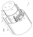
- FIG. 1 shows a typical partial perspective view of a dynamoelectric machine 10 (such as a generator or a motor, for example) comprising a rotor 12 having axially extending coils 14.
- the rotor 12 may typically be imagined as a sum of an endwinding region 26 and a rotor body region 28.
- the rotor body 28 has radially extending teeth 18.
- Chimneys 24 are radial cavities located in the rotor body 28 to provide an exit path for the cooling gas.
- Multiple cavities 20 exist between the coils 14 in the endwinding region 26 for providing circulation of a cooling gas in the endwinding region 26, and multiple spacers 16 situated between the coils 14 provide structural integrity to the coil winding and prevent contact between the coils 14.
- a retaining ring 22 is provided to envelope the coils 14 in the endwinding region 26.
- the rotor body 28 has been drawn smooth, but typically includes axial slots (not shown) for coils on top of which rotor wedges (not shown) are placed at the outer radius of the rotor body. Additionally ventilation holes (not shown) are typically present in either the rotor wedges or the rotor teeth or both. Further, between the slots, there exist rotor teeth 18 that project radially from the rotor's axis (not shown), and the space between the two sides of the innermost coil is called a pole.
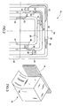
- FIG. 2 illustrates a top view of the coils 14 (or coil windings) of the machine 10 of FIG. 1, spread out on a plane, according to an embodiment of the present invention.
- Ventilation grooves 30 having an inlet 32 (meaning at least one inlet) and an outlet 34 (meaning at least one outlet) are defined in at least some of the coils 14, providing at least one path for gas flow from a first cavity 38 to a second cavity 36, or a different portion of the first cavity 38.
- the ventilation groove 30 has an inlet 32 defined to open in the first cavity 38, and the outlet 34 is defined to open in the second cavity 36.
- the outlet 34 (in phantom) of the ventilation groove 30 is defined to open in the first cavity 38.
- inlet 32 and outlet 34 are reverse configurations of the inlet 32 and outlet 34 , that is, the flow may enter from the outlet 34 and exit from the inlet 32.
- multiple inlets 32 may be used in the ventilation groove 30. It is appreciated here that though in the illustration of FIG. 2 various grooves shown are not arranged in a symmetrical fashion, in an actual embodiment the grooves will typically be arranged symmetrically about an axis 54.
- Ventilation grooves 40, 42 are other examples of ventilation grooves 30. Typically at least one path for gas flow will be provided by exactly one ventilation groove. It is further appreciated that the path defined by the ventilation grooves 30 for gas flow may be defined to open into the cavity, either from the coils 14 or from the spacers 46, 48 and such modifications providing a gas flow path between cavities 20 are within the scope of the present invention.
- Chimneys 24, which are radial cavities through the coils located in the rotor body 28, provide an exit path for the cooling gas from the endwinding region 26, as supplied by a cavity to chimney groove 52 in FIG. 2.
- ventilation grooves define paths that direct the gas flow in a selectable direction in the machine.
- the ventilation grooves may be configured to direct the gas flow from relatively cooler regions to the relatively hotter regions of the machine.
- the configuration to direct the gas flow comprises positioning inlet and exit the ventilation groove(s) based on the pressure distribution profile that exists in the endwinding region, and utilizing the fact that the flow occurs from a high pressure region to a low pressure region. It will be appreciated that a desired pressure distribution may not always be possible to attain, however, if a pressure differential across a path exists, the gas flow will always take place from the high pressure to the low pressure region.
- a desired pressure distribution in the endwinding region may be achieved in the following ways: suitably positioning the spacer 16 between the coils, relative to the inlet or the outlet of a ventilation groove, for example, pressure is typically higher near the spacer; selecting the size of the cavity between the coils; providing multiple projections (convex, concave or a combination thereof) on the coil surfaces or the rotor surface.
- Computational fluid dynamic modeling or actual testing of the machine 10 or subcomponents of the machine can be used for studying pressure distribution in the endwinding region to arrive at a suitable positioning of spacers 16 and suitable size of cavities 20. According to another contemplated aspect of the present invention illustrated by FIG.
- At least one scoop 44 is provided at least one of the spacers 16, wherein the scoop 44 is one of a concave projection, a convex projection, or a combination of concave and convex projections on the spacer 16.
- Such scoops 44 advantageously provide for varying pressure in the cavity 20 containing the spacer.
- the weight reduction grooves 50 may be configured as cavity-to-cavity ventilation grooves 30. This may be achieved by defining an inlet and an outlet from the weight reduction grooves 50 into the cavity 20 or 38. In addition to defining the inlet and the outlet, an extension of the weight reduction may be suitably defined to achieve a suitable length of the ventilation groove 30.
- the invention disclosed herein further presents a solution to increase the heat transfer in the endwinding region and advantageously utilizes weight reduction 50 grooves present in the endwinding region of the coil winding 14.
- flow passages are created inside some or all the copper turns that follow the turn from the endwinding region to inside the rotor body region, where the flow (of a coolant) is directed radially outwards towards an airgap between the rotor and the stator.
- the starting location of these passages can be in an endstrap region, where the coils run circumferentially, or in a coilside region, where the coils run axially.
- the flow in the groove 52 enters the rotor body and passes through the chimney 24, a radial passage through the copper turns, which vents the flow to the airgap, as shown in FIG. 2.
- the flow enters the rotor teeth 18, the iron between the rotor slots, either directly or through a space block adjacent to the teeth before being vented into the airgap.
- Ventilation grooves provide at least one path for gas flow from at least one first cavity to at least one of a second cavity or a different portion of the first cavity, increase the cooling capacity over that which can be provided by conventional embodiments with all paths being directly coupled to either a chimney or vent hole. Additionally when ventilation grooves of such embodiments are configured from weight-reduction grooves (that is, to serve both purposes of reducing weight and providing a path for gas flow), a simple and efficient increase in cooling is provided.
Landscapes
- Engineering & Computer Science (AREA)
- Power Engineering (AREA)
- Windings For Motors And Generators (AREA)
- Motor Or Generator Cooling System (AREA)
- Motor Or Generator Frames (AREA)
Abstract
Description
Claims (10)
- A machine (10), comprising:wherein ventilation grooves (30) having an inlet (32) and an outlet (34) are defined in the rotor (12) with at least some of the coils (14) including at least one of the ventilation grooves (30), and wherein the ventilation grooves (30) provide at least one path for gas flow from at least one first cavity (38) to at least one of (i) a second cavity (36) or (ii) a different portion of the first cavity (38).a rotor (12) comprising(a) axially extending coils (14), each coil (14) extending into an endwinding region (26),(b) a plurality of cavities (20, 36, 38) between the coils (14) in the endwinding region (26), and(c) a plurality of spacers (16) situated between the coils (14);
- The machine (10) of claim 1, wherein the ventilation grooves (30) provide the at least one path for gas flow from the at least one first cavity (38) to the second cavity (36).
- The machine (10) of claim 1, wherein the ventilation grooves (30) providing at least one path for the gas flow are configured to have the at least one path coupled to at least one cavity through at least one spacer (46 or 48).
- The machine (10) of claim 1, wherein at least one of the ventilation grooves (30) comprises a configuration to direct the gas flow in a selectable direction in the machine (10).
- The machine (10) of claim 4, wherein the configuration to direct the gas flow comprises inlet and exit positions of the at least one ventilation groove (30) based on pressure distribution in the endwinding region (26).
- The machine (10) of Claim 1, wherein at least some of the coils (14) each further comprise a plurality of weight reduction grooves (50), and
wherein at least one of the weight reduction grooves (50) is configured as at least one of the ventilation grooves (30). - A rotor (12) comprisingwherein ventilation grooves (30) having an inlet (32) and an outlet (34) are defined in the rotor (12) with at least some of the coils (14) including at least one of the ventilation grooves (30), and wherein at least one of the ventilation grooves (30) provides at least one path for gas flow from at least one first cavity (38) to at least one of (i) a second cavity (36) or (ii) a different portion of the first cavity (38);(a) axially extending coils (14), each coil (14) extending into an endwinding region (26),(b) a plurality of cavities (20, 36, 38) between the coils (14) in the endwinding region (26), and(c) a plurality of spacers (16) situated between the coils (14);
wherein at least some of the coils (14) each further comprise a plurality of weight reduction grooves (50), and wherein at least one of the weight reduction grooves (50) is configured as at least one of the ventilation grooves (30). - The rotor of claim 7, wherein the ventilation grooves (30) provide the at least one path for gas flow from the at least one first cavity (38) to the second cavity (36).
- The rotor of claim 7, wherein at least one of the ventilation grooves (30) comprises a configuration to direct the gas flow in a selectable direction in the rotor (12).
- The rotor of claim 9, wherein the configuration to direct the gas flow comprises inlet and exit positions of the at least one ventilation groove (30) based on pressure distribution in the endwinding region (26).
Applications Claiming Priority (2)
| Application Number | Priority Date | Filing Date | Title |
|---|---|---|---|
| US742034 | 2003-12-19 | ||
| US10/742,034 US6870299B1 (en) | 2003-12-19 | 2003-12-19 | Thermal management of rotor endwinding coils |
Publications (2)
| Publication Number | Publication Date |
|---|---|
| EP1544979A2 true EP1544979A2 (en) | 2005-06-22 |
| EP1544979A3 EP1544979A3 (en) | 2006-05-17 |
Family
ID=34274871
Family Applications (1)
| Application Number | Title | Priority Date | Filing Date |
|---|---|---|---|
| EP04257659A Withdrawn EP1544979A3 (en) | 2003-12-19 | 2004-12-09 | Thermal management of rotor endwinding coils |
Country Status (4)
| Country | Link |
|---|---|
| US (1) | US6870299B1 (en) |
| EP (1) | EP1544979A3 (en) |
| JP (1) | JP2005185095A (en) |
| CA (1) | CA2489631A1 (en) |
Cited By (1)
| Publication number | Priority date | Publication date | Assignee | Title |
|---|---|---|---|---|
| WO2007050464A1 (en) | 2005-10-28 | 2007-05-03 | General Electric Company | Paddled rotor spaceblocks |
Families Citing this family (6)
| Publication number | Priority date | Publication date | Assignee | Title |
|---|---|---|---|---|
| JP4682893B2 (en) * | 2006-03-27 | 2011-05-11 | 株式会社日立製作所 | Rotating electric machine rotor |
| US8115352B2 (en) | 2009-03-17 | 2012-02-14 | General Electric Company | Dynamoelectric machine coil spacerblock having flow deflecting channel in coil facing surface thereof |
| US8525376B2 (en) | 2010-10-01 | 2013-09-03 | General Electric Company | Dynamoelectric machine coil spaceblock having flow deflecting structure in coil facing surface thereof |
| JP6165340B2 (en) * | 2014-07-25 | 2017-07-19 | 三菱電機株式会社 | Rotating electric machine |
| EP3291417A1 (en) * | 2016-09-05 | 2018-03-07 | Siemens Aktiengesellschaft | Rotor coil head blocking with gas guidance |
| EP4099546A4 (en) * | 2020-01-31 | 2023-10-18 | Weg Equipamentos Elétricos S/A | Rotor and rotary electric machine |
Family Cites Families (16)
| Publication number | Priority date | Publication date | Assignee | Title |
|---|---|---|---|---|
| US2653255A (en) * | 1952-07-26 | 1953-09-22 | Westinghouse Electric Corp | Separate end-turn rotorventilation |
| US2833944A (en) * | 1957-07-22 | 1958-05-06 | Gen Electric | Ventilation of end turn portions of generator rotor winding |
| US2864014A (en) * | 1957-08-07 | 1958-12-09 | Gen Electric | Ventilation of the innermost coil of a generator rotor winding |
| JPS5625348A (en) * | 1979-08-08 | 1981-03-11 | Hitachi Ltd | Rotor for rotary electric machine cooled by gas |
| JPS5778350A (en) * | 1980-10-31 | 1982-05-17 | Hitachi Ltd | Rotor in rotary electric machine |
| US4543503A (en) | 1983-12-20 | 1985-09-24 | General Electric Company | Ventilated end turns for rotor windings of a dynamoelectric machine |
| US4709177A (en) | 1986-06-30 | 1987-11-24 | General Electric Company | Ventilated end turns for rotor windings of a dynamoelectric machine |
| US5281877A (en) | 1992-11-13 | 1994-01-25 | General Electric Company | Dynamoelectric machine rotor endwindings with corner cooling passages |
| US5252880A (en) | 1992-11-24 | 1993-10-12 | General Electric Company | Dynamoelectric machine rotor endwindings with cooling passages |
| US5644179A (en) | 1994-12-19 | 1997-07-01 | General Electric Company | Gas cooled end turns for dynamoelectric machine rotor |
| US6091168A (en) | 1998-12-22 | 2000-07-18 | Hamilton Sundstrand Corporation | Rotor for a dynamoelectric machine |
| US6339268B1 (en) | 2000-02-02 | 2002-01-15 | General Electric Company | Cooling ventilation circuit for rotor end winding and slot end region cooling |
| US6252318B1 (en) * | 2000-02-09 | 2001-06-26 | General Electric Co. | Direct gas cooled longitudinal/cross-flow rotor endwinding ventillation scheme for rotating machines with concentric coil rotors |
| US6495943B2 (en) * | 2000-12-19 | 2002-12-17 | General Electric Company | Spaceblock scoops for enhanced rotor cavity heat transfer |
| US6392326B1 (en) | 2000-12-22 | 2002-05-21 | General Electric Company | Flow-through spaceblocks with deflectors and method for increased electric generator endwinding cooling |
| US6617749B2 (en) * | 2000-12-22 | 2003-09-09 | General Electric Company | Re-entrant spaceblock configuration for enhancing cavity flow in rotor endwinding of electric power generator |
-
2003
- 2003-12-19 US US10/742,034 patent/US6870299B1/en not_active Expired - Fee Related
-
2004
- 2004-12-09 EP EP04257659A patent/EP1544979A3/en not_active Withdrawn
- 2004-12-09 CA CA002489631A patent/CA2489631A1/en not_active Abandoned
- 2004-12-17 JP JP2004366145A patent/JP2005185095A/en not_active Withdrawn
Cited By (2)
| Publication number | Priority date | Publication date | Assignee | Title |
|---|---|---|---|---|
| WO2007050464A1 (en) | 2005-10-28 | 2007-05-03 | General Electric Company | Paddled rotor spaceblocks |
| US7342345B2 (en) | 2005-10-28 | 2008-03-11 | General Electric Company | Paddled rotor spaceblocks |
Also Published As
| Publication number | Publication date |
|---|---|
| JP2005185095A (en) | 2005-07-07 |
| CA2489631A1 (en) | 2005-06-19 |
| EP1544979A3 (en) | 2006-05-17 |
| US6870299B1 (en) | 2005-03-22 |
Similar Documents
| Publication | Publication Date | Title |
|---|---|---|
| JP3721361B2 (en) | Improved cooling of generator coil ends | |
| EP0684682B1 (en) | Improvements in or relating to cooling arrangements for rotating electrical machines | |
| JP4572647B2 (en) | Permanent magnet rotating electrical machine and wind power generation system | |
| EP2230748B1 (en) | Dynamoelectric machine coil spacerblock having flow deflecting channel in coil facing surface thereof | |
| EP1557929A2 (en) | Method and apparatus for reducing hot spot temperatures on stacked field windings | |
| CN1057552A (en) | Cooling system for motor stator | |
| US5898246A (en) | Control of reluctance dynamoelectric machine cooling fluid | |
| JP2010104225A (en) | Heat transfer enhancement of dynamoelectric machine rotor | |
| CN100388595C (en) | Flow spacer block with baffles and method for increasing cooling of generator end windings | |
| EP1346457B1 (en) | Spaceblock deflector for increased electric generator endwinding cooling | |
| JP3737480B2 (en) | Space block scoop to enhance heat transfer in rotor cavity | |
| US6870299B1 (en) | Thermal management of rotor endwinding coils | |
| US7342345B2 (en) | Paddled rotor spaceblocks | |
| US6759770B1 (en) | Cooling system for modular field windings of a generator | |
| US20020079784A1 (en) | Re-entrant spaceblock configuration for enhancing cavity flow in rotor endwinding of electric power generator | |
| JP2004516795A (en) | Highly thermally conductive space block for increased cooling of generator rotor coil ends | |
| KR20090126205A (en) | Ventilation chimneys with improved heat transfer for rotors of dynamoelectric machines |
Legal Events
| Date | Code | Title | Description |
|---|---|---|---|
| PUAI | Public reference made under article 153(3) epc to a published international application that has entered the european phase |
Free format text: ORIGINAL CODE: 0009012 |
|
| AK | Designated contracting states |
Kind code of ref document: A2 Designated state(s): AT BE BG CH CY CZ DE DK EE ES FI FR GB GR HU IE IS IT LI LT LU MC NL PL PT RO SE SI SK TR |
|
| AX | Request for extension of the european patent |
Extension state: AL BA HR LV MK YU |
|
| PUAL | Search report despatched |
Free format text: ORIGINAL CODE: 0009013 |
|
| AK | Designated contracting states |
Kind code of ref document: A3 Designated state(s): AT BE BG CH CY CZ DE DK EE ES FI FR GB GR HU IE IS IT LI LT LU MC NL PL PT RO SE SI SK TR |
|
| AX | Request for extension of the european patent |
Extension state: AL BA HR LV MK YU |
|
| 17P | Request for examination filed |
Effective date: 20061117 |
|
| AKX | Designation fees paid |
Designated state(s): DE FR GB IT SE |
|
| 17Q | First examination report despatched |
Effective date: 20070824 |
|
| STAA | Information on the status of an ep patent application or granted ep patent |
Free format text: STATUS: THE APPLICATION IS DEEMED TO BE WITHDRAWN |
|
| 18D | Application deemed to be withdrawn |
Effective date: 20080304 |