EP1544728B1 - Method and computer system for evaluating the complexity of a user interface - Google Patents
Method and computer system for evaluating the complexity of a user interface Download PDFInfo
- Publication number
- EP1544728B1 EP1544728B1 EP03029167A EP03029167A EP1544728B1 EP 1544728 B1 EP1544728 B1 EP 1544728B1 EP 03029167 A EP03029167 A EP 03029167A EP 03029167 A EP03029167 A EP 03029167A EP 1544728 B1 EP1544728 B1 EP 1544728B1
- Authority
- EP
- European Patent Office
- Prior art keywords
- complexity
- device class
- layout
- layout component
- evaluation
- Prior art date
- Legal status (The legal status is an assumption and is not a legal conclusion. Google has not performed a legal analysis and makes no representation as to the accuracy of the status listed.)
- Expired - Lifetime
Links
Images


Classifications
-
- G—PHYSICS
- G06—COMPUTING OR CALCULATING; COUNTING
- G06F—ELECTRIC DIGITAL DATA PROCESSING
- G06F8/00—Arrangements for software engineering
- G06F8/30—Creation or generation of source code
- G06F8/38—Creation or generation of source code for implementing user interfaces
Definitions
- the present invention generally relates to electronic data and more particularly, relates to methods, computer program products and systems for device independent document authoring.
- Some software development platforms such as the Eclipse Platform, are designed for building integrated development environments (IDEs) that can be used to create applications as diverse as web sites, embedded JavaTM programs, C++ programs, and Enterprise JavaBeansTM.
- IDEs integrated development environments
- the publication " Interactive Design Metrics Visualization: Visula Metric Support for User Interface Design, Cpmputer-Human Interaction, 1996, Proceedings Sixth Australian Conference on Hamilton, New Zealand 24-27 Nov. 1996, Los Alamitos, CA, USA, IEEE Computer.Soc .,” discloses design metrics for guiding user interface designers to permit quick and cost-effective assessment of user interface quality and identification of usability problems.
- the metrics include a measure for layout uniformity, which is a simplification of layout complexity for a user interface design.
- Layout uniformity assesses factors in subjective judgments of visual regularity to avoid highly chaotic arrangements that are more difficult to use.
- the present invention provides computer system, method and computer program product according to the independent claims for improving the support for device independent authoring of user interface documents by generating device class specific information about the complexity of the user interface by device class.
- a complexity indicator provides this information to the author supporting the author to identify complexity problems in a user interface document related to device class specific restrictions during the development of the document.
- the author gains better control of a computer system that includes the complexity indicator and is used for the development of user interfaces for various device classes, because the complexity indicator enables the author to quickly identify and solve problems of the user interface document related to device specific restrictions.
- High complexity of a user interface typically has a negative impact on the usability of the user interface. Identifying such problems at early stages of the development usually minimizes efforts for adjusting the document to better comply with the various device class specific restrictions.
- a result of the device specific document analysis with the complexity indicator can also be that a user interface document cannot be used at all by devices belonging to a specific device class. In this case the author may not release the user interface document for the specific device class.
- FIG. 1 is a simplified block diagram of an integrated development environment 999 (IDE) that can be used for the development of user interface documents.
- the IDE can be implemented as a computer program running on a computer system that includes one or more computing devices.
- the IDE 999 includes an editor 104 for editing 405 documents, such as a user interface document 300, and an adaptation engine 105 for generating 420 device class dependent representations 301, 302 of the document 300.
- the IDE further includes a complexity indicator 121 for calculating complexity values with respect to the device specific representations 301, 302.
- the complexity indicator can be implemented as a computer program product having instructions that when loaded into a memory of the computer system can be executed by at least one processor of the computer system to perform an evaluation of the complexity of the user interface.
- the user interface document 300 includes a document description in a Renderer Independent Markup Language (RIML).
- RIML Renderer Independent Markup Language
- the present invention can be applied to any other document type, such as documents written in Hypertext Markup Language (HTML), Extensible Markup Language (XML), Java, etc.
- HTML Hypertext Markup Language
- XML Extensible Markup Language
- Java Java
- RIML is an XML based markup language.
- the user interface document can be stored in form of a file or any other suitable data structure.
- the complexity indicator 121 provides special support for the development of documents that are used in mobile applications and, therefore, need to be compatible with a variety of device classes.
- a device class includes a plurality of restrictions that are typical for devices (e.g., mobile devices) belonging to the device class.
- Adaptation engines such as the consensus adaptation engine, are known in the art.
- the adaptation engine 105 is used to generate 420 the device class specific representations 301, 302 of the document 300.
- the document 300 includes a layout component hierarchy 320.
- This hierarchy 320 can be adapted to various device classes DC1, DC2 in different ways. This may result in the different representations 301, 302 of the document 300 for various device classes DC1, DC2.
- a specific layout component 3 may be suitable for a first device class DC1 but not a second one DC2.
- This specific layout component 3 can be suppressed by the adaptation engine 103 for the second device class DC2 and, therefore, does not become part of the document's representation 302 for the second device class DC2.
- An appropriate preview tool may allow the author to choose a specific emulator for a preview.
- the output of the adaptation engine 103 is generated for the chosen emulator. The author can browse through generated sub-pages in the preview of the document.
- the complexity indicator 121 has a complexity evaluation library 121-1 for evaluating the complexity of layout components 1 to 9 used in the document 300 or its device specific representations 301, 302 and further has a complexity display 121-2 for visualizing 440 the result of the complexity evaluation.
- High complexity of layout components usually has a negative impact on the usability of the user interface that includes the layout components.
- the adaptation engine 105 receives 410 the document 300 as input and generates 420 device specific representations of the document considering specific constraints of a device class (e.g., limited display area, memory constraints).
- a first representation 301 is generated for device class DC1 and a second representation 302 is generated for device class DC2.
- Each representation can have a layout component hierarchy 321, 322 that is different from the one 320 of the original document 300.
- the adaptation engine removed layout component 4 when generating the first representation 301 and layout component 3, when generating the second representation 302.
- the complexity indicator 121 receives 430 information about layout components 1 to 9 and how these layout components are built into the layout component hierarchies 321, 322 of the document representations 301, 302.
- a layout component can include multiple basic layout elements (e.g., input fields) and group these layout elements in such a way that a specific function of the document (e.g., performing a search) is bundled in the layout component.
- layout components are also referred to as controls.
- the complexity indicator 121 determines the layout components and the layout component hierarchy 321, 322 of the respective representation 301, 302.
- the complexity indicator 121 calculates a complexity value for each layout component in its respective representation 301, 302. This can be achieved by using a complexity evaluation library 121-1 of the complexity indicator 121. It is sufficient that the complexity indicator can access the library 121-1, which may also be stored elsewhere within the IDE 999.
- the library 121-1 includes a set of complexity evaluation functions EF5-DC1, EF5-DC2, EF6-DC1, EF6-DC2, etc.
- an evaluation function exists for each layout component with respect to the various device classes DC1, DC2.
- This can also be achieved by associating the evaluation functions with specific layout component types, where each layout component is an instance of the respective layout component type. The association of the evaluation functions with the respective layout components is illustrated by a solid line between a layout component and its respective evaluation functions.
- the complexity indicator 121 applies the evaluation functions for the various device classes to the associated layout components of the respective representations 301, 302. Each applied evaluation function returns a complexity value for the respective layout component. For example, return values may range from 1 to 10, where 1 indicates a low complexity of the component and 10 indicates a high complexity of the component. Any other appropriate measure can be used instead.
- Evaluation criteria used by the evaluation functions can, for example, refer to the number of items that can be displayed simultaneously in the display area of a specific device class or to the number of broken links of the layout component, dependent of the component layout type.
- Coding section 1 shows an example of an evaluation function for a select layout element in a PDA device class.
- a Palm Pilot belongs to the PDA device class. The basic assumption is that a reasonable number of items displayed on the Palm Pilot should not exceed 12.
- Coding section 2 shows an example of an evaluation function for a select layout element in a cell phone device class.
- a Nokia 7650 belongs to the cell phone device class.
- the basic assumption is that a reasonable number of items displayed on the Nokia 7650 should not exceed 7.
- the complexity indicator aggregates the returned complexity values for the various representations 301, 302 according to the respective layout component hierarchies 321, 322. Aggregate complexity values can be determined for the various levels in the layout component hierarchies 321, 322.
- layout component 2 may represent a menu that includes two sub-menus (layout components 5 and 6).
- the aggregation algorithm may propagate the maximum complexity value of both sub-menus to the menu 2, assuming that the complexity value of the menu 2 cannot be less than the highest complexity value of is sub-menus.
- the second device class DC2 when applying the evaluation functions EF5-DC2 and EF6-DC2.
- the overall complexity of the menu 2 can still be higher.
- an evaluation function can be applied directly to the parent node.
- the sub-menus can have complexity values of "3" and "5".
- the usage of both sub-menus in the menu 2 can lead to a complexity value "7" for the menu 2 (parent node) itself.
- the complexity indicator can then visualize 440 the various complexity values for the author in a complexity display 121-2. For example, the aggregate complexity values "4" and "8" for the respective component hierarchies 321, 322 can be displayed for each device class DC1, DC2.
- FIG. 2 illustrates an alternative implementation of the complexity indicator 121, where the complexity indicator processes complexity evaluation hierarchies instead of layout component hierarchies.
- the complexity indicator 121 can include a transformer 121-3 that can transform the layout component hierarchy 321, 322 of each representation 301, 302 into a corresponding markup language independent complexity evaluation hierarchy 521, 522.
- the complexity evaluation hierarchy 521, 522 includes the same information as the respective layout component hierarchy 321, 322 but is described in a generic language to which the evaluation functions can be applied.
- Using a language independent complexity evaluation hierarchy enables the complexity indicator to use a single set of evaluation functions being associated with components c1 to c9 of the complexity evaluation hierarchy 521, 522 in the complexity library 121-1.
- the complexity hierarchy layer is an abstraction layer between the representations 301, 302 and the complexity evaluation functions of the library 121-1 that helps to avoid that an evaluation function for a layout component needs to be redundantly provided for various markup languages, such as RIML, XHTML, HTML, etc.
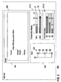
- FIG. 3 shows an alternative implementation of the complexity display 121-2 when integrated into the IDE graphical user interface (GUI).
- the complexity values for each device class DC1, DC2 are visualized as graphical bars 21, 22.
- complexity values increase from the left value 1 to the right value 10.
- Threshold values T1, T2 are used to change the appearance of the bars 21, 22 dependent on the visualized threshold value.
- complexity values below T1 have a first grid structure or a first colour.
- Complexity values between T1 and T2 have a second grid structure or a second colour and complexity values above T2 have a third grid structure or a third colour.
- Other presentations such as traffic lights changing the colour when exceeding a threshold value, are also possible.
- the complexity display 121-2 further can have a drill down section 121-2', where complexity values can be shown on different hierarchy levels down to the complexity of an isolated layout component for a selected device class.
- the drill down is made for the second device class DC2.
- the high complexity value originates from the layout component 2, whereas the complexity value of layout components 4 and 7 is relatively low.
- a further drill down can be made for each of the layout components to determine the origin of high complexity values.
- a tree-based outline editor 109 can be interfaced to the complexity indicator 121 so that, when it is displayed simultaneously on the IDE GUI, a layout component that is selected in the complexity display 121-2 is highlighted in the component hierarchy 322 shown in the tree-based outline editor 109.
- the tree-based outline editor 109 can generate an outline view of the edited document 300 or its device specific representation 301, 302, such as an XML tree view of a RIML document.
- the outline view can be a graphical display of the corresponding layout component hierarchy.
- the tree-based outline editor 109 displays the layout component hierarchy 322 of the respective representation 302 that corresponds to the device class DC2 that is currently drilled down in the complexity indicator.
- Embodiments of the invention can be implemented in digital electronic circuitry, or in computer hardware, firmware, software, or in combinations of them.
- the invention can be implemented as a computer program product, i.e., a computer program tangibly embodied in an information carrier, e.g., in a machine-readable storage device or in a propagated signal, for execution by, or to control the operation of, data processing apparatus, e.g., a programmable processor, a computer, or multiple computers.
- An computer program for device independent authoring of user interface documents including a complexity indicator as described above can be written in any form of programming language, including compiled or interpreted languages, and it can be deployed in any form, including as a stand-alone program or as a module, component, subroutine, or other unit suitable for use in a computing environment.
- a computer program can be deployed to be executed on one computer or on multiple computers at one site or distributed across multiple sites and interconnected by a communication network.
- Method steps of the invention can be performed by one or more programmable processors executing a computer program to perform functions of the invention by operating on input data and generating output. Method steps can also be performed by, and apparatus of the invention can be implemented as, special purpose logic circuitry, e.g., an FPGA (field programmable gate array) or an ASIC (application-specific integrated circuit).
- FPGA field programmable gate array
- ASIC application-specific integrated circuit
- processors suitable for the execution of a computer program include, by way of example, both general and special purpose microprocessors, and any one or more processors of any kind of digital computer.
- a processor will receive instructions and data from a read-only memory or a random access memory or both.
- the essential elements of a computer are at least one processor for executing instructions and one or more memory devices for storing instructions and data.
- a computer will also include, or be operatively coupled to receive data from or transfer data to, or both, one or more mass storage devices for storing data, e.g., magnetic, magneto-optical disks, or optical disks.
- Information carriers suitable for embodying computer program instructions and data include all forms of non-volatile memory, including by way of example semiconductor memory devices, e.g., EPROM, EEPROM, and flash memory devices; magnetic disks, e.g., internal hard disks or removable disks; magneto-optical disks; and CD-ROM and DVD-ROM disks.
- semiconductor memory devices e.g., EPROM, EEPROM, and flash memory devices
- magnetic disks e.g., internal hard disks or removable disks
- magneto-optical disks e.g., CD-ROM and DVD-ROM disks.
- the processor and the memory can be supplemented by, or incorporated in special purpose logic circuitry.
- the invention can be implemented on a computer having a display device, e.g., a cathode ray tube (CRT) or liquid crystal display (LCD) monitor, for displaying information to the user and a keyboard and a pointing device, e.g., a mouse or a trackball, by which the user can provide input to the computer.
- a display device e.g., a cathode ray tube (CRT) or liquid crystal display (LCD) monitor
- keyboard and a pointing device e.g., a mouse or a trackball
- Other kinds of devices can be used to provide for interaction with a user as well; for example, feedback provided to the user can be any form of sensory feedback, e.g., visual feedback, auditory feedback, or tactile feedback; and input from the user can be received in any form, including acoustic, speech, or tactile input.
- the invention can be implemented in a computing system that includes a back-end component, e.g., as a data server, or that includes a middleware component, e.g., an application server, or that includes a front-end component, e.g., a client computer having a graphical user interface or a Web browser through which a user can interact with an implementation of the invention, or any combination of such back-end, middleware, or front-end components.
- the components of the system can be interconnected by any form or medium of digital data communication, e.g., a communication network. Examples of communication networks include a local area network (LAN) and a wide area network (WAN), e.g., the Internet.
- LAN local area network
- WAN wide area network
- the computing system can include clients and servers.
- a client and server are generally remote from each other and typically interact through a communication network.
- the relationship of client and server arises by virtue of computer programs running on the respective computers and having a client-server relationship to each other.
Landscapes
- Engineering & Computer Science (AREA)
- Software Systems (AREA)
- General Engineering & Computer Science (AREA)
- Theoretical Computer Science (AREA)
- Human Computer Interaction (AREA)
- Physics & Mathematics (AREA)
- General Physics & Mathematics (AREA)
- User Interface Of Digital Computer (AREA)
- Testing, Inspecting, Measuring Of Stereoscopic Televisions And Televisions (AREA)
- Communication Control (AREA)
Abstract
Description
- The present invention generally relates to electronic data and more particularly, relates to methods, computer program products and systems for device independent document authoring.
- Some software development platforms, such as the Eclipse Platform, are designed for building integrated development environments (IDEs) that can be used to create applications as diverse as web sites, embedded JavaTM programs, C++ programs, and Enterprise JavaBeansTM.
- Current IDEs support the development of user interfaces for applications that are primarily foreseen to interact with a homogenous delivery context (e.g., a screen of low resolution, such as 800x600 pixels.)
- However, more and more heterogeneous devices access application servers running applications that have been developed by using an IDE. Developers have to adapt application user interfaces for different types of delivery context. This task becomes increasingly difficult with the prior art IDEs not providing sufficient support for device independent development of user interface documents.
- For example, the publication "Interactive Design Metrics Visualization: Visula Metric Support for User Interface Design, Cpmputer-Human Interaction, 1996, Proceedings Sixth Australian Conference on Hamilton, New Zealand 24-27 Nov. 1996, Los Alamitos, CA, USA, IEEE Computer.Soc.," discloses design metrics for guiding user interface designers to permit quick and cost-effective assessment of user interface quality and identification of usability problems. The metrics include a measure for layout uniformity, which is a simplification of layout complexity for a user interface design. Layout uniformity assesses factors in subjective judgments of visual regularity to avoid highly chaotic arrangements that are more difficult to use.
- The present invention provides computer system, method and computer program product according to the independent claims for improving the support for device independent authoring of user interface documents by generating device class specific information about the complexity of the user interface by device class. A complexity indicator provides this information to the author supporting the author to identify complexity problems in a user interface document related to device class specific restrictions during the development of the document. Thus, the author gains better control of a computer system that includes the complexity indicator and is used for the development of user interfaces for various device classes, because the complexity indicator enables the author to quickly identify and solve problems of the user interface document related to device specific restrictions.
- High complexity of a user interface typically has a negative impact on the usability of the user interface. Identifying such problems at early stages of the development usually minimizes efforts for adjusting the document to better comply with the various device class specific restrictions. A result of the device specific document analysis with the complexity indicator can also be that a user interface document cannot be used at all by devices belonging to a specific device class. In this case the author may not release the user interface document for the specific device class.
- The aspects of the invention will be realized and attained by means of the elements and combinations particularly pointed out in the appended claims. It is to be understood that both the foregoing general description and the following detailed description are exemplary and explanatory only and are not restrictive of the invention as described.
-
- FIG. 1
- illustrates a complexity indicator according to the invention as being part of an IDE;
- FIG. 2
- shows an alternative implementation of the complexity indicator with an abstraction layer; and
- FIG. 3
- shows an implementation of a complexity display when integrated into the IDE main window.
-
FIG. 1 is a simplified block diagram of an integrated development environment 999 (IDE) that can be used for the development of user interface documents. The IDE can be implemented as a computer program running on a computer system that includes one or more computing devices. The IDE 999 includes aneditor 104 forediting 405 documents, such as auser interface document 300, and anadaptation engine 105 for generating 420 device classdependent representations document 300. The IDE further includes acomplexity indicator 121 for calculating complexity values with respect to the devicespecific representations - In the following description, by way of example, the
user interface document 300 includes a document description in a Renderer Independent Markup Language (RIML). However, the present invention can be applied to any other document type, such as documents written in Hypertext Markup Language (HTML), Extensible Markup Language (XML), Java, etc. RIML is an XML based markup language. The user interface document can be stored in form of a file or any other suitable data structure. - The
complexity indicator 121 provides special support for the development of documents that are used in mobile applications and, therefore, need to be compatible with a variety of device classes. A device class includes a plurality of restrictions that are typical for devices (e.g., mobile devices) belonging to the device class. - Adaptation engines, such as the consensus adaptation engine, are known in the art. The
adaptation engine 105 is used to generate 420 the device classspecific representations document 300. In general, thedocument 300 includes alayout component hierarchy 320. Thishierarchy 320 can be adapted to various device classes DC1, DC2 in different ways. This may result in thedifferent representations document 300 for various device classes DC1, DC2. For example, a specific layout component 3 may be suitable for a first device class DC1 but not a second one DC2. This specific layout component 3 can be suppressed by the adaptation engine 103 for the second device class DC2 and, therefore, does not become part of the document'srepresentation 302 for the second device class DC2. An appropriate preview tool may allow the author to choose a specific emulator for a preview. The output of the adaptation engine 103 is generated for the chosen emulator. The author can browse through generated sub-pages in the preview of the document. - The
complexity indicator 121 has a complexity evaluation library 121-1 for evaluating the complexity oflayout components 1 to 9 used in thedocument 300 or its devicespecific representations - The
adaptation engine 105 receives 410 thedocument 300 as input and generates 420 device specific representations of the document considering specific constraints of a device class (e.g., limited display area, memory constraints). In the example, afirst representation 301 is generated for device class DC1 and asecond representation 302 is generated for device class DC2. Each representation can have alayout component hierarchy original document 300. In the example, the adaptation engine removedlayout component 4 when generating thefirst representation 301 and layout component 3, when generating thesecond representation 302. - The
complexity indicator 121 receives 430 information aboutlayout components 1 to 9 and how these layout components are built into thelayout component hierarchies document representations - The
complexity indicator 121 determines the layout components and thelayout component hierarchy respective representation - Further, the
complexity indicator 121 calculates a complexity value for each layout component in itsrespective representation complexity indicator 121. It is sufficient that the complexity indicator can access the library 121-1, which may also be stored elsewhere within the IDE 999. The library 121-1 includes a set of complexity evaluation functions EF5-DC1, EF5-DC2, EF6-DC1, EF6-DC2, etc. Preferably, such an evaluation function exists for each layout component with respect to the various device classes DC1, DC2. This can also be achieved by associating the evaluation functions with specific layout component types, where each layout component is an instance of the respective layout component type. The association of the evaluation functions with the respective layout components is illustrated by a solid line between a layout component and its respective evaluation functions. - The
complexity indicator 121 applies the evaluation functions for the various device classes to the associated layout components of therespective representations -
Coding section 1 shows an example of an evaluation function for a select layout element in a PDA device class. For example, a Palm Pilot belongs to the PDA device class. The basic assumption is that a reasonable number of items displayed on the Palm Pilot should not exceed 12. -
 int n = number of options
 bool sortedList = ?
 int items (area size) = 12
 int UnsorteMaximalLevelTragetKnown = 36
 int MaxScreens = 6.5
 IF (sortedList = TRUE)
       IF n <= items (area size) return 1
       IF ((x <= MaxSreens) && (n <= x * items (area size))
 return x
        ELSE return 10
 int n = number of options
 bool sortedList = ?
 int items (area size) = 7
 int UnsorteMaximalLevelTragetKnown = 20
 int MaxScreens = 6.5
 IF (sortedList = TRUE)
       IF n <= items (area size) return 1
       IF ((x <= MaxSreens) && (n <= x * items (area size))
 return x
        ELSE return 10
Claims (9)
- A computer program product for device independent authoring of user interface documents (300) including a complexity indicator (121) having instructions that when loaded into a memory of a computer or computer system can be executed by at least one processor of the computer or computer system to evaluate the complexity of a user interface that has device class specific representations (301, 302), each device class specific representation (301, 302) referring to a respective device class (DC1, DC2) and having a respective layout component hierarchy (321, 322) the computer program product (121) comprising:means to access a library (121-1) having complexity evaluation functions (EF5-DC1, EF5-DC2, EF6-DC1, EF6-DC2), which comprise evaluation criteria comprising a number of items that can be displayed simultaneously in a display area of the respective device class (DC1, DC2), to determine complexity values of layout components (1 to 9) of the respective layout component hierarchies (321, 322), where each complexity evaluation function (EF5-DC1, EF5-DC2, EF6-DC1, EF6-DC2) is associated with the layout component (5, 6) to which it is applied and returns a complexity value for the associated layout component (5, 6), wherein the complexity value is evaluated based on the evaluation criteria;means for aggregating the complexity values by device class according to the corresponding layout component hierarchy (321, 322) of the respective device class specific representation (301, 302) by using an aggregation algorithm to dermine an aggregated complexity value of a specific layout component by taking into account the complexity values of child components of said specific layout component and a complexity value of said layout component itself; anda complexity display (121-2) configured to visualize the aggregate complexity values by device class.
- The computer program product of claim 1, further comprising:a transformer (121-3) configured to transform the layout component hierarchy (321, 322) of each representation (301, 302) into a corresponding complexity evaluation hierarchy (521, 522) so that the association of each evaluation function (EF5-DC1, EF5-DC2, EF6-DC1, EF6-DC2) with its respective layout component (5, 6) is redirected through the corresponding component (c5, c6) of the respective complexity evaluation hierarchy (521, 522) and the evaluation function is applied to the corresponding component (c5, c6) of the respective complexity evaluation hierarchy (521, 522).
- The computer program product of claim 1 or 2, wherein the complexity display (121-2) has a drill down portion (121-2) for visualizing complexity values of layout components (2, 4, 7) related to a selected device class (DC2).
- The computer program product of claim 3 interfaced to a tree-based outline editor (109) for generating an outline view (322) of the representation (302) that corresponds to the selected device class (DC2) configured to highlight a layout component that is selected in the complexity display (121-2) to drill down to complexity values of child components of the selected layout component.
- A computer implemented method for device independent authoring of user interface documents (300), comprising the steps of:receiving (430) device class specific representations (301, 302) of the user interface, wherein each device class specific representation (301, 302) refers to a respective device class (DC1, DC2);determining complexity values of layout components (1 to 9) of the device class specific representations (301, 302) by applying complexity evaluation functions (EF5-DC1, EF5- DC2, EF6-DC1, EF6-DC2) that are associated with respective layout components (5, 6), wherein the complexity evaluation functions comprise evaluation criteria comprising a number of items that can be displayed simultaneously in a display area of the respective device class (DC1, DC2), and returning a complexity value for the associated layout component (5, 6), wherein the complexity value is evaluated based on the evaluation criteria;aggregating the complexity values by device class according to a corresponding layout component hierarchy (321, 322) of the respective device class specific representation (301, 302) by using an aggregation algorithm to determine an aggregated complexity value of a specific layout component by taking into account the complexity values of child components of said specific layout component and a complexity value of said layout component itself; andvisualizing the aggregate complexity values by device class.
- The method of claim 5, further comprising the step of:transforming the layout component hierarchy (321, 322) of each representation (301, 302) into a corresponding complexity evaluation hierarchy (521, 522) so that the association of each evaluation function (EF5-DC1, EF5-DC2, EF6- DC1, EF6-DC2) with its respective layout component (5, 6) is redirected through the corresponding component (c5, c6) of the respective complexity evaluation hierarchy (521, 522) and the evaluation function is applied to the corresponding component (c5, c6) of the respective complexity evaluation hierarchy (521, 522).
- The method of claim 6, wherein the visualizing step comprises:visualizing complexity values of layout components (2, 4, 7) related to a selected device class (DC2) in a drill down portion (121-2).
- A computer system having at least one computing device configured to run an integrated development environment (999) that comprises a computer program product (121) according to any one of the claims 1 to 4.
- The computer system of claim 8 when dependent on claim 3, wherein the integrated development environment (999) further comprises:a tree-based outline editor (109) for generating an outline view (322) of the representation (302) that corresponds to the selected device class (DC2) configured to highlight a layout component that is selected in the complexity display (121-2) to drill down to complexity values of child components of the selected layout component.
Priority Applications (5)
| Application Number | Priority Date | Filing Date | Title |
|---|---|---|---|
| EP03029167A EP1544728B1 (en) | 2003-12-18 | 2003-12-18 | Method and computer system for evaluating the complexity of a user interface |
| AT03029167T ATE416420T1 (en) | 2003-12-18 | 2003-12-18 | METHOD AND COMPUTER SYSTEM FOR DETERMINING THE COMPLEXITY OF A USER INTERFACE |
| DE60325076T DE60325076D1 (en) | 2003-12-18 | 2003-12-18 | Method and computer system for determining the complexity of a user interface |
| PCT/EP2004/053444 WO2005059742A1 (en) | 2003-12-18 | 2004-12-14 | Method and computer system for evaluating the complexity of a user interface |
| US10/582,937 US8959488B2 (en) | 2003-12-18 | 2004-12-14 | Method and computer system for evaluating the complexity of a user interface |
Applications Claiming Priority (1)
| Application Number | Priority Date | Filing Date | Title |
|---|---|---|---|
| EP03029167A EP1544728B1 (en) | 2003-12-18 | 2003-12-18 | Method and computer system for evaluating the complexity of a user interface |
Publications (2)
| Publication Number | Publication Date |
|---|---|
| EP1544728A1 EP1544728A1 (en) | 2005-06-22 |
| EP1544728B1 true EP1544728B1 (en) | 2008-12-03 |
Family
ID=34486245
Family Applications (1)
| Application Number | Title | Priority Date | Filing Date |
|---|---|---|---|
| EP03029167A Expired - Lifetime EP1544728B1 (en) | 2003-12-18 | 2003-12-18 | Method and computer system for evaluating the complexity of a user interface |
Country Status (5)
| Country | Link |
|---|---|
| US (1) | US8959488B2 (en) |
| EP (1) | EP1544728B1 (en) |
| AT (1) | ATE416420T1 (en) |
| DE (1) | DE60325076D1 (en) |
| WO (1) | WO2005059742A1 (en) |
Families Citing this family (6)
| Publication number | Priority date | Publication date | Assignee | Title |
|---|---|---|---|---|
| EP1526448B1 (en) | 2003-10-24 | 2008-11-12 | Sap Ag | Method and computer system for document authoring |
| US8561026B2 (en) * | 2007-11-27 | 2013-10-15 | International Business Machines Corporation | Method, apparatus and computer program for facilitating the improvement of a user interface |
| US9323418B2 (en) * | 2011-04-29 | 2016-04-26 | The United States Of America As Represented By Secretary Of The Navy | Method for analyzing GUI design affordances |
| US9135591B1 (en) * | 2014-05-15 | 2015-09-15 | Linkedin Corporation | Analysis and assessment of software library projects |
| US11061638B2 (en) | 2019-09-17 | 2021-07-13 | The Toronto-Dominion Bank | Dynamically determining an interface for presenting information to a user |
| CN118426901B (en) * | 2024-07-05 | 2024-09-27 | 杭州老板电器股份有限公司 | Visual complexity evaluation method and device for user interaction interface of household appliance |
Family Cites Families (33)
| Publication number | Priority date | Publication date | Assignee | Title |
|---|---|---|---|---|
| US5390354A (en) | 1991-03-15 | 1995-02-14 | Itt Corporation | Computerized directory pagination system and method |
| US5600789A (en) * | 1992-11-19 | 1997-02-04 | Segue Software, Inc. | Automated GUI interface testing |
| US5724262A (en) * | 1994-05-31 | 1998-03-03 | Paradyne Corporation | Method for measuring the usability of a system and for task analysis and re-engineering |
| US6091896A (en) * | 1995-12-22 | 2000-07-18 | Hewlett-Packard Company | Debugging optimized code using data change points |
| US6173286B1 (en) * | 1996-02-29 | 2001-01-09 | Nth Degree Software, Inc. | Computer-implemented optimization of publication layouts |
| US5983016A (en) * | 1996-11-12 | 1999-11-09 | International Business Machines Corporation | Execution engine in an object modeling tool |
| US6202199B1 (en) * | 1997-07-31 | 2001-03-13 | Mutek Solutions, Ltd. | System and method for remotely analyzing the execution of computer programs |
| US6658648B1 (en) * | 1997-09-16 | 2003-12-02 | Microsoft Corporation | Method and system for controlling the improving of a program layout |
| US6016394A (en) * | 1997-09-17 | 2000-01-18 | Tenfold Corporation | Method and system for database application software creation requiring minimal programming |
| US6189142B1 (en) * | 1998-09-16 | 2001-02-13 | International Business Machines Corporation | Visual program runtime performance analysis |
| US6226792B1 (en) * | 1998-10-14 | 2001-05-01 | Unisys Corporation | Object management system supporting the use of application domain knowledge mapped to technology domain knowledge |
| US6411700B1 (en) * | 1998-10-30 | 2002-06-25 | Nec America, Inc. | Telemanagement system with single point of entry |
| US6279030B1 (en) * | 1998-11-12 | 2001-08-21 | International Business Machines Corporation | Dynamic JAVA™ class selection and download based on changeable attributes |
| US6628304B2 (en) | 1998-12-09 | 2003-09-30 | Cisco Technology, Inc. | Method and apparatus providing a graphical user interface for representing and navigating hierarchical networks |
| US6199195B1 (en) * | 1999-07-08 | 2001-03-06 | Science Application International Corporation | Automatically generated objects within extensible object frameworks and links to enterprise resources |
| US6405364B1 (en) * | 1999-08-31 | 2002-06-11 | Accenture Llp | Building techniques in a development architecture framework |
| US6750885B1 (en) * | 2000-01-31 | 2004-06-15 | Journyx, Inc. | Time keeping and expense tracking server that interfaces with a user based upon a user's atomic abilities |
| JP2001306308A (en) * | 2000-04-11 | 2001-11-02 | Sap Ag | How to define a class for data-centric applications |
| CA2332102A1 (en) | 2001-01-23 | 2002-07-23 | Ibm Canada Limited-Ibm Canada Limitee | Method, apparatus, media and signals for simplifying a program listing |
| US20020156799A1 (en) * | 2001-04-24 | 2002-10-24 | Stephen Markel | System and method for verifying and correcting websites |
| GB2375030B (en) * | 2001-04-27 | 2005-05-11 | Ibm | Changing user interface following difficulty in use |
| US20030090513A1 (en) * | 2001-11-09 | 2003-05-15 | Narendran Ramakrishnan | Information personalization by partial evaluation |
| US7124398B2 (en) * | 2002-04-10 | 2006-10-17 | International Business Machines Corporation | Rapid GUI refacing of a legacy application |
| US7080323B2 (en) * | 2002-10-03 | 2006-07-18 | Sbc Properties, L.P. | Dynamic and adaptable system and method for selecting a user interface dialogue model |
| US20040090458A1 (en) * | 2002-11-12 | 2004-05-13 | Yu John Chung Wah | Method and apparatus for previewing GUI design and providing screen-to-source association |
| US7747559B2 (en) * | 2003-06-13 | 2010-06-29 | Equifax, Inc. | Systems and processes for automated criteria and attribute generation, searching, auditing and reporting of data |
| US7296264B2 (en) | 2003-07-18 | 2007-11-13 | Bea Systems, Inc. | System and method for performing code completion in an integrated development environment |
| US7308288B2 (en) * | 2003-08-22 | 2007-12-11 | Sbc Knowledge Ventures, Lp. | System and method for prioritized interface design |
| EP1526448B1 (en) | 2003-10-24 | 2008-11-12 | Sap Ag | Method and computer system for document authoring |
| JP2005275439A (en) * | 2004-03-22 | 2005-10-06 | Osamu Kanai | Ui design evaluation method and apparatus |
| US20060026506A1 (en) * | 2004-08-02 | 2006-02-02 | Microsoft Corporation | Test display module for testing application logic independent of specific user interface platforms |
| US7590972B2 (en) | 2004-10-28 | 2009-09-15 | Cogency Software, Inc. | Role-oriented development environment |
| US7984058B2 (en) * | 2005-06-02 | 2011-07-19 | Genius.Com Incorporated | Database query construction and handling |
-
2003
- 2003-12-18 EP EP03029167A patent/EP1544728B1/en not_active Expired - Lifetime
- 2003-12-18 DE DE60325076T patent/DE60325076D1/en not_active Expired - Lifetime
- 2003-12-18 AT AT03029167T patent/ATE416420T1/en not_active IP Right Cessation
-
2004
- 2004-12-14 WO PCT/EP2004/053444 patent/WO2005059742A1/en not_active Ceased
- 2004-12-14 US US10/582,937 patent/US8959488B2/en active Active
Also Published As
| Publication number | Publication date |
|---|---|
| WO2005059742A1 (en) | 2005-06-30 |
| US20070162874A1 (en) | 2007-07-12 |
| ATE416420T1 (en) | 2008-12-15 |
| US8959488B2 (en) | 2015-02-17 |
| EP1544728A1 (en) | 2005-06-22 |
| DE60325076D1 (en) | 2009-01-15 |
Similar Documents
| Publication | Publication Date | Title |
|---|---|---|
| US12086535B2 (en) | Systems and methods of a script generation engine | |
| US8850392B2 (en) | Method and computer system for document authoring | |
| US7904892B2 (en) | Systems and methods for identifying and displaying dependencies | |
| US7434207B2 (en) | Floating debugger | |
| US8356276B2 (en) | Flexible code generation | |
| US8464209B2 (en) | Using collaborative development information in a team environment | |
| EP1975795B1 (en) | Method and system for estimating resource provisioning | |
| US20030081003A1 (en) | System and method to facilitate analysis and removal of errors from an application | |
| US8701085B2 (en) | Graphical event and binding editor for software development | |
| US20110087672A1 (en) | Determining and Displaying Application Server Object Relevance | |
| US7853899B1 (en) | Configuring and extending a user interface | |
| US20120143879A1 (en) | System and Method of Presenting Relevant Application Components to a User | |
| US20050066050A1 (en) | Data conveyance management | |
| US7619991B2 (en) | User interface for modeling estimations of resource provisioning | |
| KR20080049757A (en) | Template based service management | |
| US20020066074A1 (en) | Method and system for developing and executing software applications at an abstract design level | |
| US20130212557A1 (en) | Systems and methods for managing related files in a software development environment | |
| US8959488B2 (en) | Method and computer system for evaluating the complexity of a user interface | |
| US20080244404A1 (en) | Graphical method for displaying auxiliary relationships between objects | |
| US20050210381A1 (en) | Methods and computer systems for document authoring | |
| Abrahão et al. | Designing Highly Usable Web Applications. | |
| US8533616B2 (en) | Time support for service adaptation | |
| US20100299619A1 (en) | Model for Reusable User Interface and Logic for Software Wizards | |
| US10162609B2 (en) | Model-driven object composition for data access using function-expressions | |
| EP1691278B1 (en) | Method and computer system for editing documents |
Legal Events
| Date | Code | Title | Description |
|---|---|---|---|
| PUAI | Public reference made under article 153(3) epc to a published international application that has entered the european phase |
Free format text: ORIGINAL CODE: 0009012 |
|
| AK | Designated contracting states |
Kind code of ref document: A1 Designated state(s): AT BE BG CH CY CZ DE DK EE ES FI FR GB GR HU IE IT LI LU MC NL PT RO SE SI SK TR |
|
| AX | Request for extension of the european patent |
Extension state: AL LT LV MK |
|
| RAP1 | Party data changed (applicant data changed or rights of an application transferred) |
Owner name: SAP AG |
|
| 17P | Request for examination filed |
Effective date: 20051222 |
|
| AKX | Designation fees paid |
Designated state(s): AT BE BG CH CY CZ DE DK EE ES FI FR GB GR HU IE IT LI LU MC NL PT RO SE SI SK TR |
|
| 17Q | First examination report despatched |
Effective date: 20060705 |
|
| RIN1 | Information on inventor provided before grant (corrected) |
Inventor name: SPRIESTERSBACH, AXEL Inventor name: ZIEGERT, THOMAS Inventor name: LAUFF, MARKUS Inventor name: ULMER, CEDRIC Inventor name: MA, JUN |
|
| GRAP | Despatch of communication of intention to grant a patent |
Free format text: ORIGINAL CODE: EPIDOSNIGR1 |
|
| GRAS | Grant fee paid |
Free format text: ORIGINAL CODE: EPIDOSNIGR3 |
|
| GRAA | (expected) grant |
Free format text: ORIGINAL CODE: 0009210 |
|
| AK | Designated contracting states |
Kind code of ref document: B1 Designated state(s): AT BE BG CH CY CZ DE DK EE ES FI FR GB GR HU IE IT LI LU MC NL PT RO SE SI SK TR |
|
| REG | Reference to a national code |
Ref country code: GB Ref legal event code: FG4D |
|
| REG | Reference to a national code |
Ref country code: CH Ref legal event code: EP |
|
| REG | Reference to a national code |
Ref country code: IE Ref legal event code: FG4D |
|
| REF | Corresponds to: |
Ref document number: 60325076 Country of ref document: DE Date of ref document: 20090115 Kind code of ref document: P |
|
| PG25 | Lapsed in a contracting state [announced via postgrant information from national office to epo] |
Ref country code: ES Free format text: LAPSE BECAUSE OF FAILURE TO SUBMIT A TRANSLATION OF THE DESCRIPTION OR TO PAY THE FEE WITHIN THE PRESCRIBED TIME-LIMIT Effective date: 20090314 |
|
| NLV1 | Nl: lapsed or annulled due to failure to fulfill the requirements of art. 29p and 29m of the patents act | ||
| PG25 | Lapsed in a contracting state [announced via postgrant information from national office to epo] |
Ref country code: FI Free format text: LAPSE BECAUSE OF FAILURE TO SUBMIT A TRANSLATION OF THE DESCRIPTION OR TO PAY THE FEE WITHIN THE PRESCRIBED TIME-LIMIT Effective date: 20081203 Ref country code: SI Free format text: LAPSE BECAUSE OF FAILURE TO SUBMIT A TRANSLATION OF THE DESCRIPTION OR TO PAY THE FEE WITHIN THE PRESCRIBED TIME-LIMIT Effective date: 20081203 Ref country code: NL Free format text: LAPSE BECAUSE OF FAILURE TO SUBMIT A TRANSLATION OF THE DESCRIPTION OR TO PAY THE FEE WITHIN THE PRESCRIBED TIME-LIMIT Effective date: 20081203 |
|
| PG25 | Lapsed in a contracting state [announced via postgrant information from national office to epo] |
Ref country code: MC Free format text: LAPSE BECAUSE OF NON-PAYMENT OF DUE FEES Effective date: 20081231 Ref country code: EE Free format text: LAPSE BECAUSE OF FAILURE TO SUBMIT A TRANSLATION OF THE DESCRIPTION OR TO PAY THE FEE WITHIN THE PRESCRIBED TIME-LIMIT Effective date: 20081203 Ref country code: RO Free format text: LAPSE BECAUSE OF FAILURE TO SUBMIT A TRANSLATION OF THE DESCRIPTION OR TO PAY THE FEE WITHIN THE PRESCRIBED TIME-LIMIT Effective date: 20081203 Ref country code: BG Free format text: LAPSE BECAUSE OF FAILURE TO SUBMIT A TRANSLATION OF THE DESCRIPTION OR TO PAY THE FEE WITHIN THE PRESCRIBED TIME-LIMIT Effective date: 20090303 Ref country code: BE Free format text: LAPSE BECAUSE OF FAILURE TO SUBMIT A TRANSLATION OF THE DESCRIPTION OR TO PAY THE FEE WITHIN THE PRESCRIBED TIME-LIMIT Effective date: 20081203 |
|
| REG | Reference to a national code |
Ref country code: CH Ref legal event code: PL |
|
| PG25 | Lapsed in a contracting state [announced via postgrant information from national office to epo] |
Ref country code: SE Free format text: LAPSE BECAUSE OF FAILURE TO SUBMIT A TRANSLATION OF THE DESCRIPTION OR TO PAY THE FEE WITHIN THE PRESCRIBED TIME-LIMIT Effective date: 20090303 Ref country code: AT Free format text: LAPSE BECAUSE OF FAILURE TO SUBMIT A TRANSLATION OF THE DESCRIPTION OR TO PAY THE FEE WITHIN THE PRESCRIBED TIME-LIMIT Effective date: 20081203 Ref country code: CZ Free format text: LAPSE BECAUSE OF FAILURE TO SUBMIT A TRANSLATION OF THE DESCRIPTION OR TO PAY THE FEE WITHIN THE PRESCRIBED TIME-LIMIT Effective date: 20081203 Ref country code: PT Free format text: LAPSE BECAUSE OF FAILURE TO SUBMIT A TRANSLATION OF THE DESCRIPTION OR TO PAY THE FEE WITHIN THE PRESCRIBED TIME-LIMIT Effective date: 20090504 |
|
| PG25 | Lapsed in a contracting state [announced via postgrant information from national office to epo] |
Ref country code: SK Free format text: LAPSE BECAUSE OF FAILURE TO SUBMIT A TRANSLATION OF THE DESCRIPTION OR TO PAY THE FEE WITHIN THE PRESCRIBED TIME-LIMIT Effective date: 20081203 |
|
| PLBE | No opposition filed within time limit |
Free format text: ORIGINAL CODE: 0009261 |
|
| STAA | Information on the status of an ep patent application or granted ep patent |
Free format text: STATUS: NO OPPOSITION FILED WITHIN TIME LIMIT |
|
| PG25 | Lapsed in a contracting state [announced via postgrant information from national office to epo] |
Ref country code: LI Free format text: LAPSE BECAUSE OF NON-PAYMENT OF DUE FEES Effective date: 20081231 Ref country code: IE Free format text: LAPSE BECAUSE OF NON-PAYMENT OF DUE FEES Effective date: 20081218 Ref country code: DK Free format text: LAPSE BECAUSE OF FAILURE TO SUBMIT A TRANSLATION OF THE DESCRIPTION OR TO PAY THE FEE WITHIN THE PRESCRIBED TIME-LIMIT Effective date: 20081203 Ref country code: CH Free format text: LAPSE BECAUSE OF NON-PAYMENT OF DUE FEES Effective date: 20081231 |
|
| 26N | No opposition filed |
Effective date: 20090904 |
|
| PG25 | Lapsed in a contracting state [announced via postgrant information from national office to epo] |
Ref country code: CY Free format text: LAPSE BECAUSE OF FAILURE TO SUBMIT A TRANSLATION OF THE DESCRIPTION OR TO PAY THE FEE WITHIN THE PRESCRIBED TIME-LIMIT Effective date: 20081203 Ref country code: HU Free format text: LAPSE BECAUSE OF FAILURE TO SUBMIT A TRANSLATION OF THE DESCRIPTION OR TO PAY THE FEE WITHIN THE PRESCRIBED TIME-LIMIT Effective date: 20090604 Ref country code: LU Free format text: LAPSE BECAUSE OF NON-PAYMENT OF DUE FEES Effective date: 20081218 |
|
| PG25 | Lapsed in a contracting state [announced via postgrant information from national office to epo] |
Ref country code: TR Free format text: LAPSE BECAUSE OF FAILURE TO SUBMIT A TRANSLATION OF THE DESCRIPTION OR TO PAY THE FEE WITHIN THE PRESCRIBED TIME-LIMIT Effective date: 20081203 |
|
| PG25 | Lapsed in a contracting state [announced via postgrant information from national office to epo] |
Ref country code: GR Free format text: LAPSE BECAUSE OF FAILURE TO SUBMIT A TRANSLATION OF THE DESCRIPTION OR TO PAY THE FEE WITHIN THE PRESCRIBED TIME-LIMIT Effective date: 20090304 |
|
| PG25 | Lapsed in a contracting state [announced via postgrant information from national office to epo] |
Ref country code: IT Free format text: LAPSE BECAUSE OF FAILURE TO SUBMIT A TRANSLATION OF THE DESCRIPTION OR TO PAY THE FEE WITHIN THE PRESCRIBED TIME-LIMIT Effective date: 20081203 |
|
| REG | Reference to a national code |
Ref country code: DE Ref legal event code: R082 Ref document number: 60325076 Country of ref document: DE Representative=s name: MUELLER-BORE & PARTNER PATENTANWAELTE PARTG MB, DE |
|
| REG | Reference to a national code |
Ref country code: DE Ref legal event code: R081 Ref document number: 60325076 Country of ref document: DE Owner name: SAP SE, DE Free format text: FORMER OWNER: SAP AG, 69190 WALLDORF, DE Effective date: 20141210 Ref country code: DE Ref legal event code: R082 Ref document number: 60325076 Country of ref document: DE Representative=s name: MUELLER-BORE & PARTNER PATENTANWAELTE PARTG MB, DE Effective date: 20141210 |
|
| REG | Reference to a national code |
Ref country code: FR Ref legal event code: PLFP Year of fee payment: 13 |
|
| REG | Reference to a national code |
Ref country code: FR Ref legal event code: PLFP Year of fee payment: 14 |
|
| REG | Reference to a national code |
Ref country code: FR Ref legal event code: PLFP Year of fee payment: 15 |
|
| PGFP | Annual fee paid to national office [announced via postgrant information from national office to epo] |
Ref country code: GB Payment date: 20221222 Year of fee payment: 20 Ref country code: FR Payment date: 20221222 Year of fee payment: 20 Ref country code: DE Payment date: 20220620 Year of fee payment: 20 |
|
| REG | Reference to a national code |
Ref country code: DE Ref legal event code: R071 Ref document number: 60325076 Country of ref document: DE |
|
| REG | Reference to a national code |
Ref country code: GB Ref legal event code: PE20 Expiry date: 20231217 |
|
| PG25 | Lapsed in a contracting state [announced via postgrant information from national office to epo] |
Ref country code: GB Free format text: LAPSE BECAUSE OF EXPIRATION OF PROTECTION Effective date: 20231217 |
|
| PG25 | Lapsed in a contracting state [announced via postgrant information from national office to epo] |
Ref country code: GB Free format text: LAPSE BECAUSE OF EXPIRATION OF PROTECTION Effective date: 20231217 |