EP1544721A2 - A method of using a storage switch - Google Patents
A method of using a storage switch Download PDFInfo
- Publication number
- EP1544721A2 EP1544721A2 EP04078461A EP04078461A EP1544721A2 EP 1544721 A2 EP1544721 A2 EP 1544721A2 EP 04078461 A EP04078461 A EP 04078461A EP 04078461 A EP04078461 A EP 04078461A EP 1544721 A2 EP1544721 A2 EP 1544721A2
- Authority
- EP
- European Patent Office
- Prior art keywords
- data
- port
- sink
- data packet
- storage
- Prior art date
- Legal status (The legal status is an assumption and is not a legal conclusion. Google has not performed a legal analysis and makes no representation as to the accuracy of the status listed.)
- Ceased
Links
Images


Classifications
-
- G—PHYSICS
- G06—COMPUTING OR CALCULATING; COUNTING
- G06F—ELECTRIC DIGITAL DATA PROCESSING
- G06F3/00—Input arrangements for transferring data to be processed into a form capable of being handled by the computer; Output arrangements for transferring data from processing unit to output unit, e.g. interface arrangements
- G06F3/06—Digital input from, or digital output to, record carriers, e.g. RAID, emulated record carriers or networked record carriers
- G06F3/0601—Interfaces specially adapted for storage systems
- G06F3/0628—Interfaces specially adapted for storage systems making use of a particular technique
- G06F3/0629—Configuration or reconfiguration of storage systems
- G06F3/0635—Configuration or reconfiguration of storage systems by changing the path, e.g. traffic rerouting, path reconfiguration
-
- G—PHYSICS
- G06—COMPUTING OR CALCULATING; COUNTING
- G06F—ELECTRIC DIGITAL DATA PROCESSING
- G06F13/00—Interconnection of, or transfer of information or other signals between, memories, input/output devices or central processing units
- G06F13/38—Information transfer, e.g. on bus
- G06F13/42—Bus transfer protocol, e.g. handshake; Synchronisation
- G06F13/4247—Bus transfer protocol, e.g. handshake; Synchronisation on a daisy chain bus
- G06F13/426—Bus transfer protocol, e.g. handshake; Synchronisation on a daisy chain bus using an embedded synchronisation, e.g. Firewire bus, Fibre Channel bus, SSA bus
-
- G—PHYSICS
- G06—COMPUTING OR CALCULATING; COUNTING
- G06F—ELECTRIC DIGITAL DATA PROCESSING
- G06F3/00—Input arrangements for transferring data to be processed into a form capable of being handled by the computer; Output arrangements for transferring data from processing unit to output unit, e.g. interface arrangements
- G06F3/06—Digital input from, or digital output to, record carriers, e.g. RAID, emulated record carriers or networked record carriers
- G06F3/0601—Interfaces specially adapted for storage systems
- G06F3/0602—Interfaces specially adapted for storage systems specifically adapted to achieve a particular effect
- G06F3/0626—Reducing size or complexity of storage systems
-
- G—PHYSICS
- G06—COMPUTING OR CALCULATING; COUNTING
- G06F—ELECTRIC DIGITAL DATA PROCESSING
- G06F3/00—Input arrangements for transferring data to be processed into a form capable of being handled by the computer; Output arrangements for transferring data from processing unit to output unit, e.g. interface arrangements
- G06F3/06—Digital input from, or digital output to, record carriers, e.g. RAID, emulated record carriers or networked record carriers
- G06F3/0601—Interfaces specially adapted for storage systems
- G06F3/0668—Interfaces specially adapted for storage systems adopting a particular infrastructure
- G06F3/0671—In-line storage system
- G06F3/0683—Plurality of storage devices
Definitions
- This present invention relates to the field of storage switches, and more particularly without limitation to storage area networks.
- Switch networks, or fabrics, for transmitting packets between two or more nodes are known.
- switch fabrics include a plurality of switches arranged to permit transmission of frames or data packets over different paths or channels.
- Each node has a port adapted for connection to a respective channel.
- One illustrative type of switch fabric is Fibre Channel.
- Fibre Channel is a serial interface that allows data transfer rates of 100MB/second. Future increase of the Fibre Channel data rate is planned.
- Fibre Channel The basic connection to a Fibre Channel device is made in accordance with the Fibre Channel physical interface by two serial cables, one carrying in-bound data and the other carrying out-bound data. These cables can be fibre optic or twin-axial copper cables. How the devices are to be connected together is a question of system topology. Several topologies are defined for Fibre Channel including fabric, point-to-point, and arbitrated loop.
- Fibre Channel does not rely on a common bus along which all the devices communicate. Instead, Fibre Channel arbitrated loop (FC-AL) communication between two devices relies upon any other devices between the two being able to accurately propagate the information on to the intended destination. Fibre Channel transfers occur in frames of data, with request and acknowledge activity occurring on a frame basis.
- FC-AL Fibre Channel arbitrated loop
- FC-AL devices Communications between two FC-AL devices occurs as a sequence of primitives and frames sent from one device to another.
- Payload data representative of user information is transmitted from one device to another in the form of frames.
- each frame consists of a frame header of 24 bytes followed by a payload of up to 2,048 bytes.
- the payload contains the data being transmitted, while the frame header contains context information regarding the payload data, such as the addresses of the devices involved.
- the Fibre Channel physical interface and protocol can be utilised to couple a data source, such as a host computer, to a storage switch of a storage area network (SAN).
- a data source such as a host computer
- a storage switch of a storage area network In a SAN servers typically require concurrent access to shared storage resources.
- the storage switch provides this concurrency as well as services such as zoning, i.e. the ability to segment the network and bind each server to specific disc or tape storage resources.
- the present invention provides a method of using a storage switch comprising coupling a data source, such as a server or host computer, to a port of the storage switch and coupling another port of the storage switch to a port of a data sink, such as a sequential storage device or a SAN disc.
- the data sink has at least another port that is used for coupling of the data sink to another data sink.
- the data sink that is coupled to the storage switch has a component for determining whether a data packet received from the data source is addressed to it or not. In case the data packet does not address the first data sink, the data sink forwards the data packet. This way data packets can be transmitted from the data source to both data sinks using only two ports of the storage switch such that more efficient usage of the available data rates can be made.
- the network can provide a data rate of typically 100MB/second.
- a storage device such as a tape drive, typically supports only a lower data rate of e.g. up to 30MB/second.
- a return path is provided from the data sinks to the data source through the storage switch using the same two ports of the storage switch that are used to transmit data packets from the data source to the data sinks.
- the return path provides a way to communicate status information back to the data source.
- more than two data sinks are interconnected in a daisy-chained configuration.
- data packets can flow from one data sink into the neighbouring data sink.
- the neighbouring data sink determines whether the data packet is to be processed therein or to be directed to the next neighbouring data sink in the daisy-chain.
- the neighbouring data sink repeats the process and forwards the data packet to its neighbour, until the data packet reaches its intended destination.
- data packets pass through intervening data sinks on their way from the first data sink in the daisy-chain to the destination data sink.
- This is distinguished from a bus configuration in which all nodes exchange information over a bus connecting all devices in a parallel fashion.
- dual ported FC-AL devices are used to implement the data sinks.
- At least one of the data sinks of the daisy-chained configuration is a tape library.
- the tape library comprises multiple tape drives and a tape media exchange mechanism for increased storage capacity.
- the present invention is particularly advantageous in that it reduces the number of components, in particular the number of storage switches, that are required to build a SAN. In particular fewer expensive switched network ports are required and better usage is made of the data rate provided by the network that typically substantially exceeds the storage media access bandwidth of the data sinks.
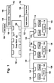
- Figure 1 shows storage switch 100 that has a plurality of ports, including ports 102 and 104.
- Data source 106 is connected to port 102 of storage switch 100 by means of cable 108.
- data source 106 is a server or host computer.
- Dual ported data sink 110 has ports 112 and 114. Further, data sink 110 has a device address that is stored in non-volatile memory 116 as well as program 118 and storage 120.
- data sink 110 is a SAN disc or a tape drive. In the latter case storage 120 is provided by a loaded tape medium.
- Port 114 of data sink 110 is connected to port 104 of storage switch 100 by means of cable 122.
- Port 112 of data sink 110 is connected to port 124 of neighbouring data sink 126 by means of cable 128.
- Data sink 126 has a design that is similar to data sink 110, i.e. data sink 126 has an additional port 130, non-volatile memory 132 for storage of a device address for data sink 126, program 134 and storage 136.
- Data sink 126 has neighbouring data sink 138, that has again a similar design, i.e. ports 140, 142, non-volatile memory 144 for storing the device address of data sink 138, program 146, and storage 148.
- Data sink 126 is connected to data sink 138 by means of cable 150 that connects ports 130 and 140.
- Data source 106 sends out data packet 152 via cable 108.
- Data packet 152 has header 154 that contains a target address and payload data 156.
- the target address is a device address of one of the data sinks 110, 126, or 138 and thus identifies the target device for data packet 152.
- Storage switch 100 receives data packet 152 at its port 102. By means of the target address of data packet 152 port 104 of storage switch 100 is identified as the output port by storage switch 100. From port 104 data packet 152 is transmitted via cable 122 to data sink 110 where it is received at port 114.
- the device address program 118 forwards data packet 152 to port 112 from where data packet 152 is transmitted via cable 128 to port 124 of neighbouring data sink 126.
- cables 108, 122, 128, and 150 as well as storage switch 100 support a data transmission rate of up to X MB/second.
- Data sinks 110, 126, and 138 support a data rate for storing of data on storage 120, 136, 138, respectively, of Y MB/second.
- data rate Y usually is much lower than data rate X
- more efficient usage of the available data rate X can be made due to the daisy-chained configuration of data sinks 110, 126, and 138.
- FIG. 2 shows a corresponding flow chart.
- a data source such as a server or host computer, sends a data packet or frame to a storage switch through a storage area network (SAN).
- the storage switch forwards the data packet to a first storage device in a daisy-chained configuration.
- the first storage device compares the target address of the data packet with its device address. If it turns out that the first storage device in the daisy-chained configuration is the addressee of the data packet,m the first storage device stores the payload data on its local storage in step 206. If the contrary is true the first storage device forwards the data packets to a second storage device in the daisy-chained configuration that neighbours the first storage device (step 208).
- the second storage device When the second storage device receives the data packet it determines in step 210 whether it is the addressee or not. If it is the addressee it stores the payload data on its local storage (step 212); otherwise it forwards the data packet to the next neighbouring third storage device in the daisy-chained configuration (step 214).
- This procedure goes on until the data packet has reached its target device by meandering through the daisy-chained configuration of storage devices.
- Figure 3 shows an alternative embodiment similar to the embodiment of figure 1. Elements of the embodiment of figure 3 that correspond to elements of the embodiment of figure 1 are designated by like reference numerals having added 200.
- cables 308, 322, 328, 350 provide for duplex connectivity between data sinks 310, 326, 338 and data source 306. This way a return communication path from each one of the data sinks 310, 326, 338 to data source 306 is provided.
- Data packet 352 has an additional entry field in header 354 for the initiator address of data source 306. Hence data packet 352 identifies both the target device to which it is addressed as well as the source or initiator address from where it originates. In the following it is assumed without limitation of generality and by way of example only that the target address of data packet 352 is the device address of data sink 338. In other words the target address that is entered in header 354 of data packet 352 matches the device address stored in non-volatile memory 344 of data sink 338.
- program 346 determines that data packet 352 is in fact addressed to data sink 338 as target address and device address match.
- the payload data is stored in local storage 348 and a status information indicative of the successful execution of the storage of the payload data or failure of storage of the payload data is generated and returned to data source 306 by means of data packet 358.
- Data packet 358 has header 360 containing the initiator address of data source 306 as target address and the original target address of data sink 338 as initiator address. In other words the address entries in the header 354 of data packet 352 are interchanged in header 360 of return data packet 358.
- the payload data of data packet 358 consists of the status information.
- Data packet 358 propagates via cable 350, data sink 326, cable 328, data sink 310, cable 322, storage switch 300 and cable 308 to data source 306.
- This way data source 306 is notified of the status of the execution of storage of the payload data it sent out.
- data source 306 may resend data packet 352 to the same target address, or in case of consistent failure of the addressed target device, to another target device in the daisy-chained configuration.
- duplex connectivity between the components in the embodiment of figure 3 is accomplished by means of fibre channel cabling.
- network data packets 352 and 358 are transmitted in the form of frames.
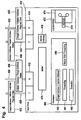
- Figure 4 shows a block diagram of an FC-AL compliant dual ported tape drive that can be utilised as a data sink device in the daisy-chained configuration of figure 1 or figure 3.
- Tape drive 410 has transmit(T)/receive(R) port 414 and T/R port 416.
- Port 414 is coupled to cable 422 to receive in-bound data packets and to cable 423 to send out-bound data packets.
- port 416 is coupled to cables 428 and 429, for out-bound and in-bound data packets, respectively.
- Tape drive 410 has non-volatile memory 416 for storing its device address and buffer 476 that serves as a transmit and receive buffer.
- Processor 460 of tape drive 410 executes firmware modules 462, 464, 466, and 468.
- Firmware module 462 serves to determine whether a data packet received at port 414 is addressed to tape drive 410.
- Firmware module 464 serves to forward a data packet that is not addressed to tape drive 410 from port 416.
- Firmware module 466 serves to execute a command that is received at port 414, such as a command for storage of data on tape medium 470 that is loaded in mechanism 472.
- Firmware module 468 serves to forward data packets received at port 416 at port 414 in order to establish a return path for returning of status information to the initiator.
- tape drive 410 receives data packet 452 via cable 422 at port 414.
- Data packet 452 is temporarily stored in buffer 476.
- Firmware module 462 reads the target address from header 454 of data packet 452 and compares it with the device address stored in non-volatile memory 416. If the target and device addresses are not the same firmware module 464 is invoked and data packet 452 is forwarded from port 416 via cable 428 to the next device in the daisy-chained configuration.
- firmware module 466 If the target address of data packet 452 matches the device address of tape drive 410 firmware module 466 is invoked. Firmware module 466 controls mechanism 472 in order to store the payload data of data packet 452 on tape medium 470 via read/write heads 474. Further firmware module 468 generates status information indicative of successful completion or failure of the storage operation. The corresponding return data packet 458 containing the status information with the initiator address as target address is generated and returned from port 414 via cable 423.
- tape drive 410 When tape drive 410 receives return path data packet 459 at port 416 via cable 429 from a neighbouring storage device in the daisy-chained configuration this invokes firmware module 468 that forwards data packet 359 along the return path from port 414 via cable 423.
Landscapes
- Engineering & Computer Science (AREA)
- Theoretical Computer Science (AREA)
- Physics & Mathematics (AREA)
- General Engineering & Computer Science (AREA)
- General Physics & Mathematics (AREA)
- Human Computer Interaction (AREA)
- Computer Networks & Wireless Communication (AREA)
- Small-Scale Networks (AREA)
- Data Exchanges In Wide-Area Networks (AREA)
- Signal Processing For Digital Recording And Reproducing (AREA)
Abstract
- coupling a data source to a first port of the storage switch,
- coupling a second port of the storage switch to a first port of a first data sink,
- coupling a second port of the first data sink to a first port of a second data sink,
Description
- Figure 1
- is a schematic block diagram showing a data source coupled to a daisy-chained configuration of data sinks through a storage switch;
- Figure 2
- is a flow diagram illustrating steps involved in transmitting a data packet from the data source to a target data sink of the daisy-chained configuration;
- Figure 3
- is a schematic block diagram of a data source coupled to a daisy-chained configuration providing a return communication path; and
- Figure 4
- is a schematic block diagram of a dual ported tape drive that can be used in a daisy-chained configuration.
- 100
- storage switch
- 102
- port
- 104
- port
- 106
- data source
- 108
- cable
- 110
- data sink
- 112
- port
- 114
- port
- 116
- non-volatile memory
- 118
- program
- 120
- storage
- 122
- able
- 124
- port
- 126
- data sink
- 128
- cable
- 130
- port
- 132
- non-volatile memory
- 134
- program
- 136
- storage
- 138
- data sink
- 140
- port
- 142
- port
- 144
- non-volatile memory
- 146
- program
- 148
- storage
- 150
- cable
- 152
- data product
- 154
- header
- 156
- payload data
- 300
- storage switch
- 302
- port
- 304
- port
- 306
- data source
- 308
- cable
- 310
- data sink
- 312
- port
- 314
- port
- 316
- non-volatile memory
- 318
- program
- 320
- storage
- 322
- cable
- 324
- port
- 326
- data sink
- 328
- cable
- 330
- port
- 332
- non-volatile memory
- 334
- program
- 336
- storage
- 338
- data sink
- 340
- port
- 342
- port
- 344
- non-volatile memory
- 346
- program
- 348
- storage
- 350
- cable
- 352
- data packet
- 354
- header
- 356
- payload data
- 358
- data packet
- 360
- header
- 410
- tape drive
- 412
- port
- 414
- port
- 422
- cable
- 423
- cable
- 428
- cable
- 429
- cable
- 452
- data packet
- 458
- data packet
- 459
- data packet
- 460
- processor
- 462
- firmware module
- 464
- firmware module
- 466
- firmware module
- 468
- firmware module
- 470
- tape medium
- 472
- mechanism
- 474
- heads
- 476
- buffer
Claims (26)
Applications Claiming Priority (2)
| Application Number | Priority Date | Filing Date | Title |
|---|---|---|---|
| GB0329576 | 2003-12-20 | ||
| GB0329576A GB2409370A (en) | 2003-12-20 | 2003-12-20 | A storage switch and plurality of data sinks |
Publications (2)
| Publication Number | Publication Date |
|---|---|
| EP1544721A2 true EP1544721A2 (en) | 2005-06-22 |
| EP1544721A3 EP1544721A3 (en) | 2008-07-30 |
Family
ID=30776201
Family Applications (1)
| Application Number | Title | Priority Date | Filing Date |
|---|---|---|---|
| EP04078461A Ceased EP1544721A3 (en) | 2003-12-20 | 2004-12-20 | A method of using a storage switch |
Country Status (3)
| Country | Link |
|---|---|
| US (1) | US20050165955A1 (en) |
| EP (1) | EP1544721A3 (en) |
| GB (1) | GB2409370A (en) |
Cited By (3)
| Publication number | Priority date | Publication date | Assignee | Title |
|---|---|---|---|---|
| WO2007118371A1 (en) | 2006-04-19 | 2007-10-25 | Hangzhou H3C Technologies Co., Ltd. | Method for accessing object disk, system and disk array for expanding capacity of the disk |
| WO2012025323A1 (en) * | 2010-08-26 | 2012-03-01 | Robert Bosch Gmbh | Method for communicating |
| US9323473B2 (en) * | 2009-01-09 | 2016-04-26 | Hewlett Packard Enterprise Development Lp | Virtual tape library |
Families Citing this family (3)
| Publication number | Priority date | Publication date | Assignee | Title |
|---|---|---|---|---|
| US8245024B2 (en) * | 2009-08-21 | 2012-08-14 | Micron Technology, Inc. | Booting in systems having devices coupled in a chained configuration |
| US9430165B1 (en) * | 2013-07-24 | 2016-08-30 | Western Digital Technologies, Inc. | Cold storage for data storage devices |
| JP2024066819A (en) * | 2022-11-02 | 2024-05-16 | キオクシア株式会社 | Memory system and information processing system |
Citations (1)
| Publication number | Priority date | Publication date | Assignee | Title |
|---|---|---|---|---|
| US6529963B1 (en) | 1998-12-29 | 2003-03-04 | Lsi Logic Corporation | Methods and apparatus for interconnecting independent fibre channel fabrics |
Family Cites Families (34)
| Publication number | Priority date | Publication date | Assignee | Title |
|---|---|---|---|---|
| US4868734A (en) * | 1984-04-30 | 1989-09-19 | Unisys Corp. | Variable rate improvement of disc cache subsystem |
| EP0185936B1 (en) * | 1984-12-14 | 1993-01-13 | Alcatel N.V. | Interface circuit arrangement for connecting data sources with data sinks, and switching systems with such an interface circuit arrangement |
| US5504873A (en) * | 1989-11-01 | 1996-04-02 | E-Systems, Inc. | Mass data storage and retrieval system |
| US5289589A (en) * | 1990-09-10 | 1994-02-22 | International Business Machines Corporation | Automated storage library having redundant SCSI bus system |
| US5410300A (en) * | 1991-09-06 | 1995-04-25 | International Business Machines Corporation | Distributed crossbar switch architecture |
| US5583868A (en) * | 1994-07-25 | 1996-12-10 | Microsoft Corporation | Method and system for combining data from multiple servers into a single continuous data stream using a switch |
| US5856980A (en) * | 1994-12-08 | 1999-01-05 | Intel Corporation | Baseband encoding method and apparatus for increasing the transmission rate over a communication medium |
| US5923654A (en) * | 1996-04-25 | 1999-07-13 | Compaq Computer Corp. | Network switch that includes a plurality of shared packet buffers |
| US5925119A (en) * | 1997-03-28 | 1999-07-20 | Quantum Corporation | Computer architecture for automated storage library |
| US6807581B1 (en) * | 2000-09-29 | 2004-10-19 | Alacritech, Inc. | Intelligent network storage interface system |
| DE19746894C2 (en) * | 1997-10-23 | 1999-10-28 | Siemens Ag | Method and radio communication system for data transmission |
| US6754206B1 (en) * | 1997-12-04 | 2004-06-22 | Alcatel Usa Sourcing, L.P. | Distributed telecommunications switching system and method |
| US6639895B1 (en) * | 1998-10-05 | 2003-10-28 | Performance Technologies, Incorporated | Fault tolerant network switch |
| DE19858493A1 (en) * | 1998-12-18 | 2000-06-29 | Xsys Interactive Research Gmbh | Local network |
| US6553408B1 (en) * | 1999-03-25 | 2003-04-22 | Dell Products L.P. | Virtual device architecture having memory for storing lists of driver modules |
| US7010607B1 (en) * | 1999-09-15 | 2006-03-07 | Hewlett-Packard Development Company, L.P. | Method for training a communication link between ports to correct for errors |
| US6772270B1 (en) * | 2000-02-10 | 2004-08-03 | Vicom Systems, Inc. | Multi-port fibre channel controller |
| US6697875B1 (en) * | 2000-06-27 | 2004-02-24 | Sun Microsystems, Inc. | Methods for building and using a network device database |
| US6981086B2 (en) * | 2000-12-21 | 2005-12-27 | National Instruments Corporation | Instrumentation system including a backplane having a switched fabric bus and instrumentation lines |
| US7000026B2 (en) * | 2000-12-22 | 2006-02-14 | Nortel Networks Limited | Multi-channel sharing in a high-capacity network |
| US7171474B2 (en) * | 2001-04-25 | 2007-01-30 | Sun Microsystems, Inc. | Persistent repository for on-demand node creation for fabric devices |
| US6876656B2 (en) * | 2001-06-15 | 2005-04-05 | Broadcom Corporation | Switch assisted frame aliasing for storage virtualization |
| US7068603B2 (en) * | 2001-07-06 | 2006-06-27 | Juniper Networks, Inc. | Cross-bar switch |
| US7215680B2 (en) * | 2001-07-26 | 2007-05-08 | Nishan Systems, Inc. | Method and apparatus for scheduling packet flow on a fibre channel arbitrated loop |
| ATE335237T1 (en) * | 2001-08-24 | 2006-08-15 | Intel Corp | A GENERAL INPUT/OUTPUT ARCHITECTURE, PROTOCOL AND CORRESPONDING PROCEDURES FOR IMPLEMENTING FLOW CONTROL |
| US6711580B2 (en) * | 2001-10-01 | 2004-03-23 | International Business Machines Corporation | Data management system, apparatus, and method to use buffered file marks |
| US6799235B2 (en) * | 2002-01-02 | 2004-09-28 | Intel Corporation | Daisy chain latency reduction |
| US6934799B2 (en) * | 2002-01-18 | 2005-08-23 | International Business Machines Corporation | Virtualization of iSCSI storage |
| US20030233396A1 (en) * | 2002-01-31 | 2003-12-18 | Digital Software Corporation | Method and apparatus for real time storage of data networking bit streams |
| US7024591B2 (en) * | 2002-07-12 | 2006-04-04 | Crossroads Systems, Inc. | Mechanism for enabling enhanced fibre channel error recovery across redundant paths using SCSI level commands |
| US20040064461A1 (en) * | 2002-10-01 | 2004-04-01 | Subramaniyam Pooni | Method and arrangement for dynamic detection of SCSI devices on linux host |
| US7386694B1 (en) * | 2002-12-17 | 2008-06-10 | Symantec Operating Corporation | System and method for reading mirrored data |
| US7899885B2 (en) * | 2003-06-27 | 2011-03-01 | At&T Intellectual Property I, Lp | Business enterprise backup and recovery system and method |
| US7366092B2 (en) * | 2003-10-14 | 2008-04-29 | Broadcom Corporation | Hash and route hardware with parallel routing scheme |
-
2003
- 2003-12-20 GB GB0329576A patent/GB2409370A/en not_active Withdrawn
-
2004
- 2004-12-20 US US11/015,849 patent/US20050165955A1/en not_active Abandoned
- 2004-12-20 EP EP04078461A patent/EP1544721A3/en not_active Ceased
Patent Citations (1)
| Publication number | Priority date | Publication date | Assignee | Title |
|---|---|---|---|---|
| US6529963B1 (en) | 1998-12-29 | 2003-03-04 | Lsi Logic Corporation | Methods and apparatus for interconnecting independent fibre channel fabrics |
Cited By (6)
| Publication number | Priority date | Publication date | Assignee | Title |
|---|---|---|---|---|
| WO2007118371A1 (en) | 2006-04-19 | 2007-10-25 | Hangzhou H3C Technologies Co., Ltd. | Method for accessing object disk, system and disk array for expanding capacity of the disk |
| EP2009552A4 (en) * | 2006-04-19 | 2010-10-06 | Hangzhou H3C Tech Co Ltd | Method for accessing object disk, system and disk array for expanding capacity of the disk |
| US8041890B2 (en) | 2006-04-19 | 2011-10-18 | Hangzhou H3C Technologies Co., Ltd. | Method for accessing target disk, system for expanding disk capacity and disk array |
| US9323473B2 (en) * | 2009-01-09 | 2016-04-26 | Hewlett Packard Enterprise Development Lp | Virtual tape library |
| US9690506B2 (en) | 2009-01-09 | 2017-06-27 | Hewlett Packard Enterprise Development Lp | Virtual tape library |
| WO2012025323A1 (en) * | 2010-08-26 | 2012-03-01 | Robert Bosch Gmbh | Method for communicating |
Also Published As
| Publication number | Publication date |
|---|---|
| GB2409370A (en) | 2005-06-22 |
| GB0329576D0 (en) | 2004-01-28 |
| EP1544721A3 (en) | 2008-07-30 |
| US20050165955A1 (en) | 2005-07-28 |
Similar Documents
| Publication | Publication Date | Title |
|---|---|---|
| EP1454440B1 (en) | Method and apparatus for providing optimized high speed link utilization | |
| JP5828966B2 (en) | Method, apparatus, system, and storage medium for realizing packet transmission in a PCIE switching network | |
| US7194550B1 (en) | Providing a single hop communication path between a storage device and a network switch | |
| US5889776A (en) | Physical layer switch system for ethernet local area network communication system | |
| US7411958B2 (en) | Method and system for transferring data directly between storage devices in a storage area network | |
| CN101052013B (en) | Method and system for realizing network equipment internal managing path | |
| EP0772323A2 (en) | Method and apparatus for tracking buffer availability | |
| US20060242312A1 (en) | Tunneling SATA targets through fibre channel | |
| JPH10135952A (en) | Fiber Channel switch using distributed queuing | |
| JP2001524727A (en) | Low latency shared memory switch structure | |
| JPH09146906A (en) | Frame synchronous storage device | |
| WO1999010814A1 (en) | Link bundling in a network | |
| JPH08256180A (en) | Data communication network equipment | |
| WO2005066818A1 (en) | Managing transmissions between devices | |
| JPH08256168A (en) | Transfer route allocation system | |
| US20100002714A1 (en) | PCI express network | |
| CN100401713C (en) | Apparatus and method for connecting configured common memory using single-ring data bus | |
| US7307995B1 (en) | System and method for linking a plurality of network switches | |
| US6741589B1 (en) | Apparatus and method for storing data segments in a multiple network switch system using a memory pool | |
| US6999460B1 (en) | Arbitrated loop port switching | |
| US7580354B2 (en) | Multi-speed cut through operation in fibre channel switches | |
| EP1544721A2 (en) | A method of using a storage switch | |
| US7054312B2 (en) | Multi-rate shared memory architecture for frame storage and switching | |
| US7222167B2 (en) | Method for managing computer system, computer executing management program, storage device, displaying device, and storage system | |
| KR100755978B1 (en) | In-band management of stacked switch groups by a single CPU |
Legal Events
| Date | Code | Title | Description |
|---|---|---|---|
| PUAI | Public reference made under article 153(3) epc to a published international application that has entered the european phase |
Free format text: ORIGINAL CODE: 0009012 |
|
| AK | Designated contracting states |
Kind code of ref document: A2 Designated state(s): AT BE BG CH CY CZ DE DK EE ES FI FR GB GR HU IE IS IT LI LT LU MC NL PL PT RO SE SI SK TR |
|
| AX | Request for extension of the european patent |
Extension state: AL BA HR LV MK YU |
|
| PUAL | Search report despatched |
Free format text: ORIGINAL CODE: 0009013 |
|
| AK | Designated contracting states |
Kind code of ref document: A3 Designated state(s): AT BE BG CH CY CZ DE DK EE ES FI FR GB GR HU IE IS IT LI LT LU MC NL PL PT RO SE SI SK TR |
|
| AX | Request for extension of the european patent |
Extension state: AL BA HR LV MK YU |
|
| RIC1 | Information provided on ipc code assigned before grant |
Ipc: G06F 13/42 20060101ALI20080624BHEP Ipc: H04L 12/56 20060101ALI20080624BHEP Ipc: G06F 3/06 20060101AFI20050308BHEP |
|
| 17P | Request for examination filed |
Effective date: 20081106 |
|
| AKX | Designation fees paid |
Designated state(s): DE FR GB |
|
| 17Q | First examination report despatched |
Effective date: 20090316 |
|
| STAA | Information on the status of an ep patent application or granted ep patent |
Free format text: STATUS: THE APPLICATION HAS BEEN REFUSED |
|
| 18R | Application refused |
Effective date: 20100601 |