EP1544667A1 - Complément fréquentiel d'images acquises par un dispositif d'acquisition à synthèse d'ouverture optique dilué, par combinaison d'images fréquentiellement complémentaires - Google Patents
Complément fréquentiel d'images acquises par un dispositif d'acquisition à synthèse d'ouverture optique dilué, par combinaison d'images fréquentiellement complémentaires Download PDFInfo
- Publication number
- EP1544667A1 EP1544667A1 EP04292895A EP04292895A EP1544667A1 EP 1544667 A1 EP1544667 A1 EP 1544667A1 EP 04292895 A EP04292895 A EP 04292895A EP 04292895 A EP04292895 A EP 04292895A EP 1544667 A1 EP1544667 A1 EP 1544667A1
- Authority
- EP
- European Patent Office
- Prior art keywords
- installation according
- image
- acquisition device
- image data
- spatial
- Prior art date
- Legal status (The legal status is an assumption and is not a legal conclusion. Google has not performed a legal analysis and makes no representation as to the accuracy of the status listed.)
- Granted
Links
Images

Classifications
-
- G—PHYSICS
- G02—OPTICS
- G02B—OPTICAL ELEMENTS, SYSTEMS OR APPARATUS
- G02B27/00—Optical systems or apparatus not provided for by any of the groups G02B1/00 - G02B26/00, G02B30/00
- G02B27/58—Optics for apodization or superresolution; Optical synthetic aperture systems
-
- G—PHYSICS
- G06—COMPUTING OR CALCULATING; COUNTING
- G06T—IMAGE DATA PROCESSING OR GENERATION, IN GENERAL
- G06T5/00—Image enhancement or restoration
- G06T5/73—Deblurring; Sharpening
Definitions
- the invention relates to the field of image acquisition, and more precisely the acquisition of images using an acquisition device to Optical opening synthesis.
- the acquisition of certain images can require the use of large observation instruments or even very large, diameters, or the implementation of imaging interferometers.
- the instrument of observation constitutes what is called a Optical aperture synthesis acquisition device, the pupil of which is composed of several sub-pupils each collecting part of the forehead incident wave; the latter being recombined coherently so that the acquisition device delivers images whose spatial resolution depends both on the telescope diameters and their spacing.
- range of spatial frequency cancellation a range on which the MTF has a zero value or almost zero, that a range on which the FTM has a low value considering the measurement noise.
- the MTF of an observation instrument can be defined as the module of the Fourier transform of its response impulse.
- the quality of an image can only be optimal when the MTF of the observation instrument that acquires the image does not have a range cancellation of spatial frequencies. In other words, for the same optical cutoff frequency, plus an FTM includes frequencies missing spatial minus the associated image quality is good.
- spacing two by two between its sub-entrance pupils must be less than the sum of the radii of said entrance sub-pupils.
- obtaining an FTM without a cancellation range imposes the use a compact composite pupil. This degrades the ratio congestion / spatial resolution, and therefore limits the interest of interferometry in terms of acquisition of high resolution images, especially in the case spatial observations directed to space as to the earth.
- the object of the invention is therefore to improve the situation in the case of a acquisition of images using a synthesis acquisition device optical opening.
- the invention proposes to enrich (or supplement at least partially) in spatial frequency components, the image of a zone delivered by a first synthetic aperture acquisition device optical, diluted type, using complementary spatial frequencies contained in an image, substantially of that same area, issued by a source that can be for example a database of pre-existing images or a second image acquisition device.
- the source delivers second image data according to spatial frequencies that encompass at least each beach of cancellation so that the processing means deliver an image of the area complete observation in terms of spatial frequencies.
- the object of the invention is to enable the acquisition of images of high, high, and good resolution from a device Diluted type optical aperture synthesis acquisition method.
- An installation according to the invention I first comprises at least one first optical aperture synthesis (or SOO) acquisition device D1 responsible for observing a selected area in order to deliver first data representative of this area.
- the first image data is preferentially luminance image data whose transformation of Fourier presents, as will be seen later, some components zero frequencies before the cutoff frequency of the first device D1 acquisition. It includes here four telescopes, materialized by their entrance pupils P1 to P4 and by the central O closures associated. Good heard, the number of telescopes of the first device D1 can be different four. It is enough for it to be greater than or equal to two.
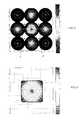
- the first acquisition device D1 is of the so-called diluted type. It has a modulation transfer function (or FTM) comprising example, as shown in FIG. 3, four cancellation ranges of Z spatial frequencies before its spatial cutoff frequency.
- Figure 3 illustrates more precisely the two-dimensional map (2D) of the frequencies spatial data, perceived by the first acquisition device D1, normalized by its sampling frequency (inverse of the sampling interval), chosen here equal to twice the optical cutoff frequency of the first device D1.
- Figure 3 represents ten or so FTM contour lines, contrast measurement, normalized to one (1) for the zero frequency, with which the first device D1 perceives the frequencies space.
- the band on the right side of FIG. the scale of the normalized contrast.
- the first acquisition device D1 delivers, for example, images high spatial resolution, at a sampling rate of two meters. He therefore perceives high spatial frequencies. He also receives low spatial frequencies. Here Z cancellation beaches are located in intermediate space frequencies between the high and low spatial frequencies.
- the images delivered by the first device D1 not include all the components of spatial frequencies less than its cutoff frequency. Therefore, these images are certainly high resolution, but their quality is not good.
- the installation I comprises, in addition to the first device D1, at least one source delivering second image data whose spatial resolution is lower than that of the first acquisition device D1 and which are substantially representative of the area observed by said first device D1 acquisition.
- These second image data are preferably same type as the first image data, ie data luminance image.
- these second image data correspond to spatial frequencies which belong to at least one at least part of at least one of the Z cancellation ranges of the MTF of the first acquisition device D1.
- This source can be a database of pre-existing images. But, as illustrated in Figure 2, it can also be presented under form of a second D2 image acquisition device having a lower spatial resolution than that of the first acquisition device D1.
- a such second device D2 consists for example of a single telescope, materialized by its entrance pupil P 'and the closure O' associated.
- the second acquisition device D2 delivers, for example, images degraded spatial resolution compared to the first acquisition device D1, here by a factor of two. Due to its configuration, its MTF does not present no cancellation range of spatial frequencies. It is however important note that the FTM of the second acquisition device D2 could present one or more ranges of cancellation of spatial frequencies, therefore that they differ at least in part from those of the first device D1 acquisition. In other words, the second acquisition device D2 can also be synthetic optical opening diluted.
- the MTF of the second acquisition device D2 does not have a spatial frequency cancellation range and completely encompasses the cancellation ranges of the MTF of the first acquisition device D1.
- FIG. 4 illustrates more precisely the two-dimensional map (2D) of the spatial frequencies perceived by the second acquisition device D2 and indicates, for the latter, the corresponding contrast (ie the MTF) normalized to one (1) for the zero frequency.
- the band on the right side of Figure 4 represents the scale of the normalized contrast.
- the second acquisition device D2 perceives as much as possible of spatial frequencies in common with the acquisition device D1, below cancellation ranges Z, that is to say, here, towards the low frequencies space.
- the first acquisition device D1 and the second device D2 are, in the example illustrated in FIG. of the same platform.
- This platform is for example installed on a spacecraft, such as an observation satellite or a station space in orbit around the earth (or any other star) and charged to observe the earth or space.
- the first D1 and second D2 acquisition devices can easily acquire the same field, but following spatial resolutions and spectral sensitivities (domain of wavelengths of observation).
- the first device D1 acquisition acquires the "landscape" in panchromatic mode
- the second acquisition device D2 acquires this same landscape mode multispectral and with a lower spatial resolution.
- the definition of the spectral masks of the second acquisition device D2 is such their sum (or that of a subset), possibly weighted, is exactly equal to the spectral mask of the first acquisition device D1.
- the luminance perceived by a sensor is the resultant of the integration of the spectral luminance (function of the wavelength) weighted by the spectral sensitivity (spectral mask) of the instrument acquisition.
- first D1 and second D2 acquisition devices could to be installed on different spacecraft whenever they observe substantially the same area.
- the second acquisition device D2 is for example a wide-field observation instrument allowing observation (or global monitoring of an extended area at medium or low resolution space, and it transmits to the first acquisition device D1, by wave, the location of areas of field interest significantly narrower to imager with a higher resolution.
- first D1 and second D2 acquisition devices are installed in the same land station or well in different ground stations as soon as they observe substantially the same area.
- the source is a base of image data of low or medium spatial resolution
- this one is preferentially implanted in a ground station
- the first device acquisition D1 is then installed either on a spacecraft, or in a land station, possibly the same as the one where the database.
- the installation according to the invention finally comprises a treatment module MT responsible for combining the first and second image data delivered respectively by the first acquisition device D1 and the source (here the second acquisition device D2), in order to deliver an image of the zone of observation which is enriched in spatial frequency components.
- a treatment module MT responsible for combining the first and second image data delivered respectively by the first acquisition device D1 and the source (here the second acquisition device D2), in order to deliver an image of the zone of observation which is enriched in spatial frequency components.
- the processing module MT is installed in the same spacecraft as the first D1 and second D2 acquisition devices, to which he is thus physically connected, possibly via electronic, electrical equipment or optical. But, the processing module MT can be separated from the first D1 and second D2 acquisition devices. It can even be advantageous for energy consumption issues, even necessary if the processing and storage capacities are not sufficient. In this case, the processing module MT is installed in a earth station and receives first and second image data from the spacecraft, by wave.
- the MT processing module may under certain circumstances be very favorable only to combine, that is to say summon (or merge), the frequency contributions (in the sense of Fourier) of the images delivered by the first D1 and second D2 acquisition devices.
- the images delivered by the first D1 and second D2 acquisition devices substantially correspond to a same zone, are concomitant (or quasi-concomitant) and compatible in terms of wavelength ranges of observation, and geometrically correspond, that is to say that they are substantially at the same scale and geometrically recalibrated.
- the images always contain low information frequencies which, when combined, result in slight degradation picture quality. Therefore, a simple summation of contributions frequency of the images delivered by the first D1 and second D2 acquisition devices certainly leads to an improvement of image quality, but not an optimal image quality.
- Noise levels and FTM levels are usually known. This filtering consists more precisely of deconvolute the first and / or second image data in view of their FTM levels and / or their respective noise levels.
- the operator * here designates the convolution.
- Deconvolution seeks to estimate the object o from the joint observations m 1 and m 2 .
- the deconvolution filters g 1 and g 2 are then determined such that the estimator ⁇ composed of the sum of the two images convolved respectively by g 1 and g 2 is as close as possible to o. Choosing the numerical criterion for defining the degree of error between o and o leads to different deconvolution methods.
- E here denotes the mathematical expectation, and ⁇ u ⁇ designates the norm Euclidean image u.
- Wiener filter is the optimal inverse linear filtering method in the sense of the quadratic error average.
- Such a filter is described in particular in the document "Signal Analysis, McGraw-Hill International Editions, Electrical & Electronical Engineering Series, Singapore, Malaysia, ISBN 0-07-048460-0, 431 pp., Papoulis A., 1987.
- the MV processing module When images of the same area are concomitant and consistent with the wavelength domain of observation, but that they are not on the same scale, the MV processing module perform a geometric mapping before proceeding to the combination of their spatial frequency components. More precisely because of differences in spatial resolution between first D1 and second D2 acquisition devices, the IM2B raw image issued by the second acquisition device D2 must be at least enlarged ("Zoom"), so as to be on the same scale as the raw image IM1 B delivered by the first acquisition device D1. Moreover, in the case general, the geometric characteristics of shooting are a priori different for the D1 and D2 devices (detectors different angles of sight, etc.). These differences induce geometric deformations that add to the scale effect that must be corrected before proceeding with the combination.
- mapping operation consists of extract from both images their low spatial frequencies in order to compare and deduce the law of scale and possibly deformation to apply to one to match the other.
- the MT processing module must perform the geometrical matching of the images, delivered by the first D1 and second D2 acquisition devices, before proceeding to the filtering (or deconvolution). It is also important to note that the module MT processing can perform geometric mapping followed by filtering, without deconvolution if it is not necessary. Moreover, the processing module MT can perform a deconvolution followed by filtering, without making the mapping geometric if it is not necessary. Finally, as indicated previously, when the conditions are optimal the processing module MT may only perform filtering.
- deconvolution can be performed before or after the combination.
- the MT processing module can proceed to their combination (or fusion).
- This combination consists in most cases of performing the sum of the filtered images, especially when a deconvolution has been previously carried out.
- the combination of images may be more complex. This is particularly the case when the images can not be exactly considered as coming from the same landscape (temporal, spatial and spectral coherences).
- the combination of images does not consist of a simple merger, as described above. It requires what the skilled person calls a restoration. This consists of retrieving information from a priori knowledge (for example physical models), physical measurements available, even partial ones, under the constraint of mathematical criteria on the image (generally based on considerations of regularity and positivity of images).
- the processing module MT uses images from the source (D2) as a priori information supplied to a reconstruction algorithm of the missing frequency components in the images delivered by the first acquisition device D1.
- the processing module MT can be realized in the form of electronic circuits, software (or computer) modules, or combination of circuits and software.
- an installation in which images from two sources of images were combined at least a source consisting of a synthetic aperture acquisition device diluted optics.
- the invention applies more generally to the combination of N images (N being greater than or equal to 2), from N sources different images, at least one of which is an acquisition device optical opening synthesis diluted.
Landscapes
- Physics & Mathematics (AREA)
- General Physics & Mathematics (AREA)
- Optics & Photonics (AREA)
- Engineering & Computer Science (AREA)
- Theoretical Computer Science (AREA)
- Image Processing (AREA)
- Image Analysis (AREA)
- Microscoopes, Condenser (AREA)
- Closed-Circuit Television Systems (AREA)
Abstract
Description
- au moins un premier dispositif d'acquisition à synthèse d'ouverture optique, à résolution spatiale choisie et comportant une fonction de transfert de modulation (FTM) présentant une ou plusieurs plages d'annulation de fréquences spatiales et capable de délivrer des premières données d'image représentatives d'une zone d'observation, selon des fréquences spatiales en dehors des plages d'annulation,
- au moins une source délivrant des secondes données d'image dont la résolution spatiale est inférieure à celle du premier dispositif et qui sont représentatives sensiblement de la zone d'observation, selon des fréquences spatiales qui appartiennent au moins à une partie au moins de l'une au moins des plages,
- des moyens de traitement chargés de combiner les premières et secondes données d'image de manière à délivrer une image de la zone d'observation complétée en composantes de fréquences spatiales.
- les moyens de traitement peuvent être chargés de filtrer par déconvolution les premières et/ou secondes données d'image et de les combiner, en tenant compte de leurs niveaux de FTM et/ou de leurs niveaux de bruit. Il est important de noter que la déconvolution peut être effectuée avant la combinaison ou bien après,
- les moyens de traitement peuvent être chargés d'extraire des premières et/ou secondes données d'image celles qui correspondent à une basse résolution spatiale, de manière à faire correspondre géométriquement les images associées avant de procéder au filtrage et/ou à la combinaison,
- le second dispositif d'acquisition d'images présente par exemple une résolution spatiale moins fine que celle du premier dispositif d'acquisition d'images,
- le second dispositif d'acquisition d'images peut être, par exemple, de type multispectral,
- le premier dispositif d'acquisition d'images peut être, par exemple, de type panchromatique,
- le premier dispositif d'acquisition d'images peut comprendre au moins deux télescopes définissant chacun une sous-pupille d'entrée,
- les premier et second dispositifs d'acquisition d'images peuvent être implantés sensiblement en un même lieu, comme par exemple sur une même plate-forme spatiale, comme par exemple un satellite d'observation,
- en variante, les premier et second dispositifs d'acquisition peuvent être implantés sur des engins spatiaux différents communiquant tous les deux avec les moyens de traitement,
- les moyens de traitement peuvent être installés sur un engin spatial ou bien dans une station terrestre (dans ce cas ils communiquent par voie d'ondes avec chaque engin spatial d'observation).
- la figure 1 illustre de façon schématique une coupe d'une fonction de transfert de modulation (FTM), présentant deux plages d'annulation de fréquences spatiales (Z1, Z2), en fonction de la fréquence spatiale,
- la figure 2 illustre de façon schématique un exemple de réalisation d'une installation d'acquisition d'images selon l'invention,
- la figure 3 illustre de façon schématique la carte bidimensionnelle des fréquences spatiales perçues par le premier dispositif d'acquisition (D1) de l'installation de la figure 2, suivant un contraste normalisé à un (1) pour la fréquence nulle (les fréquences spatiales sont normalisées par la fréquence d'échantillonnage de D1, définie comme l'inverse du pas d'échantillonnage),
- la figure 4 illustre de façon schématique la carte bidimensionnelle des fréquences spatiales (en conservant la même normalisation que celle de la figure 3) perçues par le second dispositif d'acquisition (D2) de l'installation de la figure 2, suivant un contraste normalisé à un (1) pour la fréquence nulle.
Claims (16)
- Installation d'acquisition d'images (I), comprenant au moins un premier dispositif d'acquisition (D1) à synthèse d'ouverture optique à résolution spatiale choisie et comportant une fonction de transfert de modulation présentant au moins une plage d'annulation de fréquences spatiales et propre à délivrer des premières données d'image représentatives d'une zone d'observation, selon des fréquences spatiales en dehors de ladite plage, caractérisée en ce qu'elle comprend en outre i) au moins une source (D2) de secondes données d'image de résolution spatiale inférieure à celle dudit premier dispositif (D1) et représentatives sensiblement de ladite zone d'observation, selon des fréquences spatiales appartenant au moins à une partie au moins de ladite plage, et ii) des moyens de traitement (MT) agencés pour combiner lesdites premières et secondes données d'image de manière à délivrer une image de ladite zone d'observation complétée en composantes de fréquences spatiales.
- Installation selon la revendication 1, caractérisée en ce que ladite source (D2) délivre des secondes données d'image représentatives sensiblement de ladite zone d'observation, selon des fréquences spatiales comprenant au moins celles de ladite plage d'annulation de sorte que lesdits moyens de traitement (MT) délivrent une image de ladite zone d'observation complétée en terme de fréquences spatiales.
- Installation selon l'une des revendications 1 et 2, caractérisée en ce que lesdits moyens de traitement (MT) sont agencés pour filtrer par déconvolution lesdites premières et/ou secondes données d'image et pour les combiner, en fonction de leurs niveaux de fonction de transfert de modulation et/ou de leurs niveaux de bruit.
- Installation selon l'une des revendications 1 à 3, caractérisée en ce que lesdits moyens de traitement (MT) sont agencés pour extraire desdites premières et/ou secondes données d'image celles correspondant à une basse résolution spatiale, de manière à faire correspondre géométriquement les images associées avant de procéder audit filtrage et/ou à ladite combinaison.
- Installation selon l'une des revendications 1 à 4, caractérisée en ce que ladite source (D2) est une base de données comportant lesdites secondes données d'image(s).
- Installation selon l'une des revendications 1 à 4, caractérisée en ce que ladite source (D2) est un second dispositif d'acquisition d'images.
- Installation selon la revendication 6, caractérisée en ce que ledit second dispositif d'acquisition d'images (D2) est à résolution spatiale moins fine que ledit premier dispositif d'acquisition d'images (D1).
- Installation selon l'une des revendications 6 et 7, caractérisée en ce que ledit second dispositif d'acquisition d'images (D2) est de type multispectral.
- Installation selon l'une des revendications 1 à 8, caractérisée en ce que ledit premier dispositif d'acquisition d'images (D1) est de type panchromatique.
- Installation selon l'une des revendications 1 à 9, caractérisée en ce que ledit premier dispositif d'acquisition d'images (D1) comprend au moins deux télescopes.
- Installation selon l'une des revendications 1 à 10, caractérisée en ce que lesdits premier (D1) et second (D2) dispositifs d'acquisition d'images sont installés sensiblement en un même lieu.
- Installation selon la revendication 11, caractérisée en ce que lesdits premier (D1) et second (D2) dispositifs d'acquisition sont installés sur un même engin spatial communiquant avec lesdits moyens de traitement (MT).
- Installation selon l'une des revendications 1 à 11, caractérisée en ce que lesdits premier (D1) et second (D2) dispositifs d'acquisition sont installés sur des engins spatiaux différents communiquant avec lesdits moyens de traitement (MT).
- Installation selon l'une des revendications 12 et 13, caractérisée en ce que lesdits moyens de traitement (MT) sont installés sur l'un desdits engins spatiaux.
- Installation selon l'une des revendications 12 et 13, caractérisée en ce que lesdits moyens de traitement (MT) sont installés dans une station au sol agencée pour communiquer par voie d'ondes avec chaque engin.
- Installation selon l'une des revendications 12 à 15, caractérisée en ce que chaque engin spatial est un satellite d'observation.
Applications Claiming Priority (2)
| Application Number | Priority Date | Filing Date | Title |
|---|---|---|---|
| FR0314753 | 2003-12-15 | ||
| FR0314753A FR2863735B1 (fr) | 2003-12-15 | 2003-12-15 | Completement frequentiel d'images acquises par un dispositif d'acquistion a synthese d'ouverture optique dilue, par combinaison d'images frequentiellement complementaires |
Publications (2)
| Publication Number | Publication Date |
|---|---|
| EP1544667A1 true EP1544667A1 (fr) | 2005-06-22 |
| EP1544667B1 EP1544667B1 (fr) | 2009-04-29 |
Family
ID=34508678
Family Applications (1)
| Application Number | Title | Priority Date | Filing Date |
|---|---|---|---|
| EP04292895A Expired - Lifetime EP1544667B1 (fr) | 2003-12-15 | 2004-12-06 | Complément fréquentiel d'images acquises par un dispositif d'acquisition à synthèse d'ouverture optique dilué, par combinaison d'images fréquentiellement complémentaires |
Country Status (5)
| Country | Link |
|---|---|
| EP (1) | EP1544667B1 (fr) |
| AT (1) | ATE430328T1 (fr) |
| DE (1) | DE602004020858D1 (fr) |
| ES (1) | ES2325582T3 (fr) |
| FR (1) | FR2863735B1 (fr) |
Citations (1)
| Publication number | Priority date | Publication date | Assignee | Title |
|---|---|---|---|---|
| US5905591A (en) * | 1997-02-18 | 1999-05-18 | Lockheed Martin Corporation | Multi-aperture imaging system |
-
2003
- 2003-12-15 FR FR0314753A patent/FR2863735B1/fr not_active Expired - Fee Related
-
2004
- 2004-12-06 AT AT04292895T patent/ATE430328T1/de not_active IP Right Cessation
- 2004-12-06 ES ES04292895T patent/ES2325582T3/es not_active Expired - Lifetime
- 2004-12-06 EP EP04292895A patent/EP1544667B1/fr not_active Expired - Lifetime
- 2004-12-06 DE DE602004020858T patent/DE602004020858D1/de not_active Expired - Lifetime
Patent Citations (1)
| Publication number | Priority date | Publication date | Assignee | Title |
|---|---|---|---|---|
| US5905591A (en) * | 1997-02-18 | 1999-05-18 | Lockheed Martin Corporation | Multi-aperture imaging system |
Non-Patent Citations (3)
| Title |
|---|
| HARVEY J E ET AL: "PERFORMANCE CHARACTERISTICS OF PHASED ARRAY AND THINNED APERTURE OPTICAL TELESCOPES", OPTICAL ENGINEERING, SOC. OF PHOTO-OPTICAL INSTRUMENTATION ENGINEERS. BELLINGHAM, US, vol. 27, no. 9, 1 September 1988 (1988-09-01), pages 762 - 768, XP000000358, ISSN: 0091-3286 * |
| LUCKE R L: "Fundamentals of wide-field sparse-aperture imaging", IEEE AEROSPACE CONFERENCE PROCEEDINGS, BIG SKY, MT, USA, 10-17 MARCH,, vol. 3, 20 March 2001 (2001-03-20), PISCATAWAY, NJ, USA, pages 1401 - 1419, XP010548367 * |
| PARENTI R R: "Fourier-space image restoration", LINCOLN LABORATORY JOURNAL, SPRING-SUMMER 1995, 1995, LICOLN LAB, MIT, USA, XP008033196 * |
Also Published As
| Publication number | Publication date |
|---|---|
| FR2863735B1 (fr) | 2006-03-03 |
| EP1544667B1 (fr) | 2009-04-29 |
| DE602004020858D1 (de) | 2009-06-10 |
| FR2863735A1 (fr) | 2005-06-17 |
| ATE430328T1 (de) | 2009-05-15 |
| ES2325582T3 (es) | 2009-09-09 |
Similar Documents
| Publication | Publication Date | Title |
|---|---|---|
| CA2592293C (fr) | Procede de traitement d'images mettant en oeuvre le georeferencement automatique d'images issues d'un couple d'images pris dans le meme plan focal | |
| EP2567537B1 (fr) | Procede d'imagerie polychrome | |
| EP1843295B1 (fr) | Procédé de restitution de mouvements de la ligne de visée d'un instrument optique | |
| EP3824269A2 (fr) | Procédé et systèmes de caracterisation optique non invasive d'un milieu hétérogène | |
| FR3054897A1 (fr) | Procede d'elaboration d'une image numerique, produit programme d'ordinateur et systeme optique associes | |
| FR3021127A1 (fr) | Systeme et procede d'acquisition d'images hyperspectrales | |
| Mighell et al. | Wfpc2 observations of star clusters in the magellanic clouds: I. the lmc globular cluster hodge 11 | |
| EP3326150A1 (fr) | Procédé de visualisation d'un spot laser | |
| CA2290673C (fr) | Perfectionnement a l'acquisition d'image par balayage pousse-balai | |
| FR2749398A1 (fr) | Procede et dispositif de geodesie et/ou d'imagerie par traitement de signaux satellitaires | |
| FR3066301A1 (fr) | Procede de traitement d’une image optique acquise en presence d’aerosols et/ou de nuages dans l’atmosphere | |
| FR3073631B1 (fr) | Instrument d'observation stereoscopique comportant un unique ensemble de detection, notamment pour satellite | |
| FR2645976A1 (fr) | Appareil electronique d'holographie | |
| EP1544667B1 (fr) | Complément fréquentiel d'images acquises par un dispositif d'acquisition à synthèse d'ouverture optique dilué, par combinaison d'images fréquentiellement complémentaires | |
| FR3081590A1 (fr) | Procede d’augmentation de resolution spatiale d’une image multi-spectrale a partir d’une image panchromatique | |
| Keller | Solar polarimetry close to the diffraction limit | |
| EP3427225B1 (fr) | Procédé de traitement d'images | |
| EP1445578A1 (fr) | Dispositif perfectionné de mesures astrométriques à deux téléscopes, dont un astrométrique | |
| EP1141648A1 (fr) | Procede et systeme d'aide a la visee pour arme legere | |
| EP3839814B1 (fr) | Instrument d'observation optique embarque a resolution spatiale et spectrale variables | |
| EP3165875B1 (fr) | Procede d'acquisition d'images par un instrument optique spatial ou aeroporte avec champ de vision etendu | |
| Labriji | Shadow imaging of geostationary satellites | |
| CA2647307A1 (fr) | Dispositif de formation de spectre sur un capteur optique a rejet spatial | |
| FR2928008A1 (fr) | Dispositif d'imagerie a deflecteurs. | |
| FR3049066A1 (fr) | Systeme de surveillance et de detection d’un evenement a la surface terrestre par une constellation de satellites |
Legal Events
| Date | Code | Title | Description |
|---|---|---|---|
| PUAI | Public reference made under article 153(3) epc to a published international application that has entered the european phase |
Free format text: ORIGINAL CODE: 0009012 |
|
| AK | Designated contracting states |
Kind code of ref document: A1 Designated state(s): AT BE BG CH CY CZ DE DK EE ES FI FR GB GR HU IE IS IT LI LT LU MC NL PL PT RO SE SI SK TR |
|
| AX | Request for extension of the european patent |
Extension state: AL BA HR LV MK YU |
|
| RIN1 | Information on inventor provided before grant (corrected) |
Inventor name: BLANC, PHILIPPE |
|
| 17P | Request for examination filed |
Effective date: 20051214 |
|
| AKX | Designation fees paid |
Designated state(s): AT BE BG CH CY CZ DE DK EE ES FI FR GB GR HU IE IS IT LI LT LU MC NL PL PT RO SE SI SK TR |
|
| RAP1 | Party data changed (applicant data changed or rights of an application transferred) |
Owner name: ALCATEL LUCENT |
|
| GRAP | Despatch of communication of intention to grant a patent |
Free format text: ORIGINAL CODE: EPIDOSNIGR1 |
|
| GRAS | Grant fee paid |
Free format text: ORIGINAL CODE: EPIDOSNIGR3 |
|
| GRAA | (expected) grant |
Free format text: ORIGINAL CODE: 0009210 |
|
| RAP1 | Party data changed (applicant data changed or rights of an application transferred) |
Owner name: THALES |
|
| AK | Designated contracting states |
Kind code of ref document: B1 Designated state(s): AT BE BG CH CY CZ DE DK EE ES FI FR GB GR HU IE IS IT LI LT LU MC NL PL PT RO SE SI SK TR |
|
| REG | Reference to a national code |
Ref country code: GB Ref legal event code: FG4D Free format text: NOT ENGLISH |
|
| REG | Reference to a national code |
Ref country code: CH Ref legal event code: EP |
|
| REF | Corresponds to: |
Ref document number: 602004020858 Country of ref document: DE Date of ref document: 20090610 Kind code of ref document: P |
|
| REG | Reference to a national code |
Ref country code: IE Ref legal event code: FG4D |
|
| REG | Reference to a national code |
Ref country code: ES Ref legal event code: FG2A Ref document number: 2325582 Country of ref document: ES Kind code of ref document: T3 |
|
| PG25 | Lapsed in a contracting state [announced via postgrant information from national office to epo] |
Ref country code: PT Free format text: LAPSE BECAUSE OF FAILURE TO SUBMIT A TRANSLATION OF THE DESCRIPTION OR TO PAY THE FEE WITHIN THE PRESCRIBED TIME-LIMIT Effective date: 20090829 Ref country code: FI Free format text: LAPSE BECAUSE OF FAILURE TO SUBMIT A TRANSLATION OF THE DESCRIPTION OR TO PAY THE FEE WITHIN THE PRESCRIBED TIME-LIMIT Effective date: 20090429 Ref country code: LT Free format text: LAPSE BECAUSE OF FAILURE TO SUBMIT A TRANSLATION OF THE DESCRIPTION OR TO PAY THE FEE WITHIN THE PRESCRIBED TIME-LIMIT Effective date: 20090429 Ref country code: AT Free format text: LAPSE BECAUSE OF FAILURE TO SUBMIT A TRANSLATION OF THE DESCRIPTION OR TO PAY THE FEE WITHIN THE PRESCRIBED TIME-LIMIT Effective date: 20090429 |
|
| PG25 | Lapsed in a contracting state [announced via postgrant information from national office to epo] |
Ref country code: PL Free format text: LAPSE BECAUSE OF FAILURE TO SUBMIT A TRANSLATION OF THE DESCRIPTION OR TO PAY THE FEE WITHIN THE PRESCRIBED TIME-LIMIT Effective date: 20090429 Ref country code: SE Free format text: LAPSE BECAUSE OF FAILURE TO SUBMIT A TRANSLATION OF THE DESCRIPTION OR TO PAY THE FEE WITHIN THE PRESCRIBED TIME-LIMIT Effective date: 20090729 Ref country code: IS Free format text: LAPSE BECAUSE OF FAILURE TO SUBMIT A TRANSLATION OF THE DESCRIPTION OR TO PAY THE FEE WITHIN THE PRESCRIBED TIME-LIMIT Effective date: 20090829 Ref country code: SI Free format text: LAPSE BECAUSE OF FAILURE TO SUBMIT A TRANSLATION OF THE DESCRIPTION OR TO PAY THE FEE WITHIN THE PRESCRIBED TIME-LIMIT Effective date: 20090429 |
|
| REG | Reference to a national code |
Ref country code: IE Ref legal event code: FD4D |
|
| PG25 | Lapsed in a contracting state [announced via postgrant information from national office to epo] |
Ref country code: IE Free format text: LAPSE BECAUSE OF FAILURE TO SUBMIT A TRANSLATION OF THE DESCRIPTION OR TO PAY THE FEE WITHIN THE PRESCRIBED TIME-LIMIT Effective date: 20090429 Ref country code: RO Free format text: LAPSE BECAUSE OF FAILURE TO SUBMIT A TRANSLATION OF THE DESCRIPTION OR TO PAY THE FEE WITHIN THE PRESCRIBED TIME-LIMIT Effective date: 20090429 Ref country code: DK Free format text: LAPSE BECAUSE OF FAILURE TO SUBMIT A TRANSLATION OF THE DESCRIPTION OR TO PAY THE FEE WITHIN THE PRESCRIBED TIME-LIMIT Effective date: 20090429 Ref country code: EE Free format text: LAPSE BECAUSE OF FAILURE TO SUBMIT A TRANSLATION OF THE DESCRIPTION OR TO PAY THE FEE WITHIN THE PRESCRIBED TIME-LIMIT Effective date: 20090429 Ref country code: CZ Free format text: LAPSE BECAUSE OF FAILURE TO SUBMIT A TRANSLATION OF THE DESCRIPTION OR TO PAY THE FEE WITHIN THE PRESCRIBED TIME-LIMIT Effective date: 20090429 |
|
| PG25 | Lapsed in a contracting state [announced via postgrant information from national office to epo] |
Ref country code: SK Free format text: LAPSE BECAUSE OF FAILURE TO SUBMIT A TRANSLATION OF THE DESCRIPTION OR TO PAY THE FEE WITHIN THE PRESCRIBED TIME-LIMIT Effective date: 20090429 |
|
| PLBE | No opposition filed within time limit |
Free format text: ORIGINAL CODE: 0009261 |
|
| STAA | Information on the status of an ep patent application or granted ep patent |
Free format text: STATUS: NO OPPOSITION FILED WITHIN TIME LIMIT |
|
| PG25 | Lapsed in a contracting state [announced via postgrant information from national office to epo] |
Ref country code: BG Free format text: LAPSE BECAUSE OF FAILURE TO SUBMIT A TRANSLATION OF THE DESCRIPTION OR TO PAY THE FEE WITHIN THE PRESCRIBED TIME-LIMIT Effective date: 20090729 |
|
| 26N | No opposition filed |
Effective date: 20100201 |
|
| PG25 | Lapsed in a contracting state [announced via postgrant information from national office to epo] |
Ref country code: MC Free format text: LAPSE BECAUSE OF NON-PAYMENT OF DUE FEES Effective date: 20100701 |
|
| PG25 | Lapsed in a contracting state [announced via postgrant information from national office to epo] |
Ref country code: GR Free format text: LAPSE BECAUSE OF FAILURE TO SUBMIT A TRANSLATION OF THE DESCRIPTION OR TO PAY THE FEE WITHIN THE PRESCRIBED TIME-LIMIT Effective date: 20090730 |
|
| PG25 | Lapsed in a contracting state [announced via postgrant information from national office to epo] |
Ref country code: LU Free format text: LAPSE BECAUSE OF NON-PAYMENT OF DUE FEES Effective date: 20091206 |
|
| PG25 | Lapsed in a contracting state [announced via postgrant information from national office to epo] |
Ref country code: HU Free format text: LAPSE BECAUSE OF FAILURE TO SUBMIT A TRANSLATION OF THE DESCRIPTION OR TO PAY THE FEE WITHIN THE PRESCRIBED TIME-LIMIT Effective date: 20091030 |
|
| PG25 | Lapsed in a contracting state [announced via postgrant information from national office to epo] |
Ref country code: TR Free format text: LAPSE BECAUSE OF FAILURE TO SUBMIT A TRANSLATION OF THE DESCRIPTION OR TO PAY THE FEE WITHIN THE PRESCRIBED TIME-LIMIT Effective date: 20090429 |
|
| PG25 | Lapsed in a contracting state [announced via postgrant information from national office to epo] |
Ref country code: CY Free format text: LAPSE BECAUSE OF FAILURE TO SUBMIT A TRANSLATION OF THE DESCRIPTION OR TO PAY THE FEE WITHIN THE PRESCRIBED TIME-LIMIT Effective date: 20090429 |
|
| REG | Reference to a national code |
Ref country code: FR Ref legal event code: PLFP Year of fee payment: 12 |
|
| REG | Reference to a national code |
Ref country code: FR Ref legal event code: PLFP Year of fee payment: 13 |
|
| REG | Reference to a national code |
Ref country code: FR Ref legal event code: PLFP Year of fee payment: 14 |
|
| PGFP | Annual fee paid to national office [announced via postgrant information from national office to epo] |
Ref country code: DE Payment date: 20171129 Year of fee payment: 14 |
|
| PGFP | Annual fee paid to national office [announced via postgrant information from national office to epo] |
Ref country code: NL Payment date: 20181213 Year of fee payment: 15 |
|
| PGFP | Annual fee paid to national office [announced via postgrant information from national office to epo] |
Ref country code: BE Payment date: 20181126 Year of fee payment: 15 Ref country code: GB Payment date: 20181129 Year of fee payment: 15 Ref country code: CH Payment date: 20181217 Year of fee payment: 15 Ref country code: FR Payment date: 20181127 Year of fee payment: 15 |
|
| PGFP | Annual fee paid to national office [announced via postgrant information from national office to epo] |
Ref country code: IT Payment date: 20181220 Year of fee payment: 15 Ref country code: ES Payment date: 20190102 Year of fee payment: 15 |
|
| REG | Reference to a national code |
Ref country code: DE Ref legal event code: R119 Ref document number: 602004020858 Country of ref document: DE |
|
| PG25 | Lapsed in a contracting state [announced via postgrant information from national office to epo] |
Ref country code: DE Free format text: LAPSE BECAUSE OF NON-PAYMENT OF DUE FEES Effective date: 20190702 |
|
| REG | Reference to a national code |
Ref country code: CH Ref legal event code: PL |
|
| REG | Reference to a national code |
Ref country code: NL Ref legal event code: MM Effective date: 20200101 |
|
| REG | Reference to a national code |
Ref country code: BE Ref legal event code: MM Effective date: 20191231 |
|
| GBPC | Gb: european patent ceased through non-payment of renewal fee |
Effective date: 20191206 |
|
| PG25 | Lapsed in a contracting state [announced via postgrant information from national office to epo] |
Ref country code: NL Free format text: LAPSE BECAUSE OF NON-PAYMENT OF DUE FEES Effective date: 20200101 |
|
| PG25 | Lapsed in a contracting state [announced via postgrant information from national office to epo] |
Ref country code: GB Free format text: LAPSE BECAUSE OF NON-PAYMENT OF DUE FEES Effective date: 20191206 Ref country code: IT Free format text: LAPSE BECAUSE OF NON-PAYMENT OF DUE FEES Effective date: 20191206 Ref country code: FR Free format text: LAPSE BECAUSE OF NON-PAYMENT OF DUE FEES Effective date: 20191231 |
|
| PG25 | Lapsed in a contracting state [announced via postgrant information from national office to epo] |
Ref country code: CH Free format text: LAPSE BECAUSE OF NON-PAYMENT OF DUE FEES Effective date: 20191231 Ref country code: BE Free format text: LAPSE BECAUSE OF NON-PAYMENT OF DUE FEES Effective date: 20191231 Ref country code: LI Free format text: LAPSE BECAUSE OF NON-PAYMENT OF DUE FEES Effective date: 20191231 |
|
| REG | Reference to a national code |
Ref country code: ES Ref legal event code: FD2A Effective date: 20210531 |
|
| PG25 | Lapsed in a contracting state [announced via postgrant information from national office to epo] |
Ref country code: ES Free format text: LAPSE BECAUSE OF NON-PAYMENT OF DUE FEES Effective date: 20191207 |