EP1544525A1 - Solenoid operated hydraulic valve - Google Patents
Solenoid operated hydraulic valve Download PDFInfo
- Publication number
- EP1544525A1 EP1544525A1 EP20040027358 EP04027358A EP1544525A1 EP 1544525 A1 EP1544525 A1 EP 1544525A1 EP 20040027358 EP20040027358 EP 20040027358 EP 04027358 A EP04027358 A EP 04027358A EP 1544525 A1 EP1544525 A1 EP 1544525A1
- Authority
- EP
- European Patent Office
- Prior art keywords
- valve
- electromagnet
- magnetic pole
- sleeve
- housing
- Prior art date
- Legal status (The legal status is an assumption and is not a legal conclusion. Google has not performed a legal analysis and makes no representation as to the accuracy of the status listed.)
- Granted
Links
Images


Classifications
-
- F—MECHANICAL ENGINEERING; LIGHTING; HEATING; WEAPONS; BLASTING
- F16—ENGINEERING ELEMENTS AND UNITS; GENERAL MEASURES FOR PRODUCING AND MAINTAINING EFFECTIVE FUNCTIONING OF MACHINES OR INSTALLATIONS; THERMAL INSULATION IN GENERAL
- F16K—VALVES; TAPS; COCKS; ACTUATING-FLOATS; DEVICES FOR VENTING OR AERATING
- F16K31/00—Actuating devices; Operating means; Releasing devices
- F16K31/02—Actuating devices; Operating means; Releasing devices electric; magnetic
- F16K31/06—Actuating devices; Operating means; Releasing devices electric; magnetic using a magnet, e.g. diaphragm valves, cutting off by means of a liquid
- F16K31/0603—Multiple-way valves
- F16K31/0624—Lift valves
- F16K31/0634—Lift valves with fixed seats positioned between movable valve members
- F16K31/0637—Lift valves with fixed seats positioned between movable valve members with ball shaped valve members
-
- F—MECHANICAL ENGINEERING; LIGHTING; HEATING; WEAPONS; BLASTING
- F01—MACHINES OR ENGINES IN GENERAL; ENGINE PLANTS IN GENERAL; STEAM ENGINES
- F01L—CYCLICALLY OPERATING VALVES FOR MACHINES OR ENGINES
- F01L13/00—Modifications of valve-gear to facilitate reversing, braking, starting, changing compression ratio, or other specific operations
- F01L13/0005—Deactivating valves
-
- F—MECHANICAL ENGINEERING; LIGHTING; HEATING; WEAPONS; BLASTING
- F01—MACHINES OR ENGINES IN GENERAL; ENGINE PLANTS IN GENERAL; STEAM ENGINES
- F01L—CYCLICALLY OPERATING VALVES FOR MACHINES OR ENGINES
- F01L13/00—Modifications of valve-gear to facilitate reversing, braking, starting, changing compression ratio, or other specific operations
- F01L13/0015—Modifications of valve-gear to facilitate reversing, braking, starting, changing compression ratio, or other specific operations for optimising engine performances by modifying valve lift according to various working parameters, e.g. rotational speed, load, torque
- F01L13/0031—Modifications of valve-gear to facilitate reversing, braking, starting, changing compression ratio, or other specific operations for optimising engine performances by modifying valve lift according to various working parameters, e.g. rotational speed, load, torque by modification of tappet or pushrod length
-
- F—MECHANICAL ENGINEERING; LIGHTING; HEATING; WEAPONS; BLASTING
- F01—MACHINES OR ENGINES IN GENERAL; ENGINE PLANTS IN GENERAL; STEAM ENGINES
- F01L—CYCLICALLY OPERATING VALVES FOR MACHINES OR ENGINES
- F01L13/00—Modifications of valve-gear to facilitate reversing, braking, starting, changing compression ratio, or other specific operations
- F01L13/0015—Modifications of valve-gear to facilitate reversing, braking, starting, changing compression ratio, or other specific operations for optimising engine performances by modifying valve lift according to various working parameters, e.g. rotational speed, load, torque
- F01L13/0036—Modifications of valve-gear to facilitate reversing, braking, starting, changing compression ratio, or other specific operations for optimising engine performances by modifying valve lift according to various working parameters, e.g. rotational speed, load, torque the valves being driven by two or more cams with different shape, size or timing or a single cam profiled in axial and radial direction
-
- F—MECHANICAL ENGINEERING; LIGHTING; HEATING; WEAPONS; BLASTING
- F01—MACHINES OR ENGINES IN GENERAL; ENGINE PLANTS IN GENERAL; STEAM ENGINES
- F01L—CYCLICALLY OPERATING VALVES FOR MACHINES OR ENGINES
- F01L1/00—Valve-gear or valve arrangements, e.g. lift-valve gear
- F01L1/12—Transmitting gear between valve drive and valve
- F01L1/18—Rocking arms or levers
- F01L2001/186—Split rocking arms, e.g. rocker arms having two articulated parts and means for varying the relative position of these parts or for selectively connecting the parts to move in unison
-
- F—MECHANICAL ENGINEERING; LIGHTING; HEATING; WEAPONS; BLASTING
- F01—MACHINES OR ENGINES IN GENERAL; ENGINE PLANTS IN GENERAL; STEAM ENGINES
- F01L—CYCLICALLY OPERATING VALVES FOR MACHINES OR ENGINES
- F01L13/00—Modifications of valve-gear to facilitate reversing, braking, starting, changing compression ratio, or other specific operations
- F01L2013/10—Auxiliary actuators for variable valve timing
- F01L2013/105—Hydraulic motors
-
- Y—GENERAL TAGGING OF NEW TECHNOLOGICAL DEVELOPMENTS; GENERAL TAGGING OF CROSS-SECTIONAL TECHNOLOGIES SPANNING OVER SEVERAL SECTIONS OF THE IPC; TECHNICAL SUBJECTS COVERED BY FORMER USPC CROSS-REFERENCE ART COLLECTIONS [XRACs] AND DIGESTS
- Y10—TECHNICAL SUBJECTS COVERED BY FORMER USPC
- Y10T—TECHNICAL SUBJECTS COVERED BY FORMER US CLASSIFICATION
- Y10T137/00—Fluid handling
- Y10T137/8593—Systems
- Y10T137/86493—Multi-way valve unit
- Y10T137/86574—Supply and exhaust
- Y10T137/86622—Motor-operated
Definitions
- the invention relates to an electromagnetic hydraulic valve according to the preamble forming Features of claim 1, and it is particularly advantageous at a 3/2-way switching valve for controlling a variable valve train an internal combustion engine feasible.
- From DE 199 084 40 A1 is a generic electromagnetic Hydraulic valve previously known, which is designed as a 3/2-way switching valve and essentially an electromagnet with an axially movable Magnetic anchor and a valve member with at least two valve seats and a corresponding with at least one valve seat closing ball consists.
- the electromagnet is doing by a hollow cylindrical plastic bobbin with an electrical plug contact, at least one in the bobbin received coil winding and a coil winding surrounding Magnet housing formed, wherein the hollow cylinder of the plastic bobbin at least partially formed as an anchor space of the magnet armature is, which is lined with an amagnetic metal sleeve.
- the magnet housing the electromagnet is in contrast designed as a cylinder tube sleeve, one end face forming an annular bottom in the sleeve interior is angled and the other end face has several flanged tabs, with which the magnet housing with the insertable in the same plastic bobbin connected is.
- a cast in the plastic bobbin Metal disc and a inserted into the hollow cylinder of the bobbin Polkern also form an upper magnetic pole of the electromagnet, while under magnetic pole by a in the hollow cylinder the bobbin insertable and over the bottom of the magnet housing with this magnetic conductive extension of the valve member of the Hydraulic valve is formed.
- This valve part consists essentially of a hollow cylindrical valve housing having a front pressure port and each formed as a radial opening in the lateral surface thereof Consumer terminal and a tank connection has and in the Hollow cylinder between the pressure port and the consumer port and between this and the tank port of one of the valve seats the valve part is arranged.
- the two valve seats are each as Axial monocyte formed in the bottom of two cup-shaped deep-drawn parts, the over its peripheral surfaces by press fit in the hollow cylinder of the valve housing attached and connected by a plastic sleeve.
- a disadvantage of this known electromagnetic hydraulic valve is However, that it consists of relatively many items, although partially, such as the magnet housing and the valve seats are produced without cutting, of which However, some, such as the valve body of the valve member and the armature and the pole core of the upper magnetic pole of the electromagnet, relatively solid and due to their structural design only can be produced by machining production process. The cutting production caused by the relatively long machine cycle times, the necessary Tools and device and the material used a considerable Production costs, which has ultimately proved uneconomical. In addition, the complexity increases due to the large number of individual parts the final assembly of the hydraulic valve, so that in the production of this known Hydraulic valve with unfavorable production costs is to be expected.
- the invention is therefore based on the object, an electromagnetic Hydraulic valve, in particular 3/2-way switching valve to control a variable Ventiltriebs an internal combustion engine, to design, which is made of relatively consists of few and simply designed items and is characterized by a low production and assembly costs and low production costs distinguished.
- this object is achieved by an electromagnetic hydraulic valve solved according to the preamble of claim 1 such that at least the valve housing of the valve member and / or the lower magnetic pole of the electromagnet are formed as non-cutting producible items, the lower Magnetic pole with the mounting flange of the hydraulic valve as one piece Integral component formed and at the same time as a plug-in receptacle for the valve housing is provided.
- the valve housing of the valve member is as simple cylindrical Rohhabschnitt formed by cutting without cutting is cut to length by a long tube accurately.
- the consumer connection and the tank port of the hydraulic valve is then axially punctured staggered radial openings in the lateral surface of the Valve housing introduced, depending on the application, each of the two connections either only by a radial breakthrough or by two themselves oppositely arranged radial openings in the lateral surface of the Valve housing can be formed and the longitudinal axes of the connections around 90 ° offset or can be arranged parallel to each other.
- the lower magnetic pole of the electromagnet in a further embodiment the inventively designed electromagnetic hydraulic valve formed as by Stanz assert producible web collar sleeve whose Bridge forms the mounting flange of the hydraulic valve.
- the sleeve part of this Web collar sleeve has an outer diameter, the inner diameter the armature space of the electromagnet lining metal sleeve corresponds and is plugged into this metal sleeve such that the collar of the lower magnetic pole at the bottom of the magnet housing of the electromagnet magnetically conductive.
- this collar has thereby to a half of a radius of about half the outer diameter of the magnet housing, while on the other half of the Collar of the web designed as a mounting flange of the lower magnetic pole followed.
- This bridge is in an advantageous design to its free Towards the end tapering and points at this end again such a radius that at the pivot point of the radius a mounting hole can be arranged for a screw.
- the lower magnetic pole also has as Another feature of a circular punched, in which the armature at least partially immersed in current supply of the electromagnet.
- the diameter of the magnet armature starting from the valve-side end side at least partially fit exactly to the diameter of the circular punch, to the smallest possible air gap between the armature and the lower magnetic pole an optimal transition of the magnetic field lines from Magnetic armature to reach the lower magnetic pole.
- the mounting of the lower magnetic pole on the electromagnet then takes place in such a way that first, the armature space of the electromagnet lining metal sleeve is inserted into the plastic bobbin and then under Inserting an O-ring seal the magnet housing onto the plastic bobbin attached and crimped on this. After that, the Magnetic armature inserted into the armature space of the electromagnet and the lower Magnetic pole with its sleeve part as far inserted into the metal sleeve until its Collar on the bottom of the magnet housing rests.
- This can be advantageous Way the lower magnetic pole and the magnet housing of the electromagnet finally by point or ring induction or laser welding be connected to each other.
- the upper magnetic pole the electromagnet also as producible by punching collar sleeve form, which is poured into the plastic bobbin of the electromagnet becomes.
- This collar sleeve lies with the inner surface of its sleeve part on the armature space of the electromagnet lining metal sleeve and is about their preferably perpendicular projecting from the sleeve part collar magnetically connected to the magnet housing.
- For bearing fixation of upper magnetic pole in the plastic bobbin has this in addition in his Collar several recesses, in which the injection molding of Plastic bobbin form corresponding plastic transitions.
- special advantageous recesses have four evenly on Scope of the collar arranged, rectangular shaped notches proven However, it is also possible, this by coaxial punch holes in Collar of the upper magnetic pole to replace.
- the armature of the electromagnet in a further embodiment the inventively designed electromagnetic hydraulic valve as formed on both sides open hollow cylinder sleeve, which also without cutting through Extruding with subsequent punching of the soil can be produced.
- Material for the armature has thereby a low-carbon cold heading wire, which is normally annealed after extrusion, as particularly suitable proven, as it is characterized by good flow properties and at the same time a good magnetic flux guide.
- the training of the magnet armature as Hollow cylinder sleeve has been particularly in terms of its low weight as proved advantageous, since the magnet armature thus only a very small Hysteresis is afflicted.
- Opening of the hollow cylinder sleeve a complementary trained centering one with the closing ball and one of the valve seats of the valve part in Operative connection standing second closing body are used in such a way that this can be moved axially and radially backlash of the armature.
- the second closing body of the valve part is in an expedient development the inventively designed hydraulic valve preferably as Plastic injection molded part is formed and consists essentially of a Cylindrical pin as a basic body, which integrally formed several radially on the lateral surface Axial Operationsrippen has. These Axial Resultsrippen lie on the Valve side end face of the armature and serve to center the second closing body within the valve housing.
- the electromagnet When energized the electromagnet is then simultaneously with the closing the connection between the pressure connection and the tank connection the connection between the pressure connection and the consumer connection opened by the second closing body on the plunger pin its valve-side end, the closing ball from the second valve seat pushed out against the pressure of the hydraulic pressure medium.
- About the now opened second valve seat and the overlying radial opening of the Consumer connection in the valve housing can thus be the hydraulic consumer be supplied with the hydraulic pressure medium.
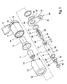
- FIG. 1 From Figures 1 to 3 is clearly an electromagnetic hydraulic valve 1, which serves as a 3/2-way switching valve for controlling a variable valve train an internal combustion engine is formed and substantially an electromagnet 2 with an axially movable armature 3 and from a valve member 4 having two valve seats 5, 6 and one corresponding to the valve seat 6 Closing ball 7 consists.
- an electromagnetic hydraulic valve 1 which serves as a 3/2-way switching valve for controlling a variable valve train an internal combustion engine is formed and substantially an electromagnet 2 with an axially movable armature 3 and from a valve member 4 having two valve seats 5, 6 and one corresponding to the valve seat 6 Closing ball 7 consists.
- the solenoid 2 is doing by a hollow cylindrical plastic bobbin 8 with an electrical Plug contact 9, a recorded in the bobbin 8 coil winding 10 and a coil winding 10 enclosing the magnet housing 11th formed, wherein the magnet housing 11 as a deep-drawn cylinder tube sleeve is formed, one end face of an annular bottom 12 forming is angled into the sleeve interior and the other end face several flanged lugs 13 to the connection with the bobbin 8 has.
- Hollow cylinder of the plastic bobbin 8 is also in the usual way Way as the armature 3 of the electromagnet 2 receiving armature space 14 is formed, in which an upper magnetic pole 15 and a lower magnetic pole 16 protrude and lined with an amagnetic metal sleeve 17 is.
- FIGS. 2 and 3 show that within the hollow cylinder 20 of the valve housing 18 in each case between the Pressure port P and the consumer port A and between the consumer port A and the tank connection T one of the valve seats 5, 6 of the Valve part 4 is arranged, wherein the valve seats 5, 6 each as axial breakthrough in the bottom 21, 22 of two cup-shaped deep-drawn parts 23, 24 are formed are, over their peripheral surfaces by press fit in the hollow cylinder 20th the valve housing 18 are attached. With the thus formed valve part.
- valve member 4 for sealing the valve seat against Pressure medium leaks additionally has an outer sealing ring 25.
- valve housing 18 of the valve member 4 and the lower magnetic pole 16 of the electromagnet 2 inventively designed as non-cutting producible items are.
- the lower magnetic pole 16 with the mounting flange 26 of the hydraulic valve 1 additionally formed as a one-piece integral component, which at the same time provided as a plug-in receptacle for the valve housing 18 of the valve member 4 is.
- valve housing 18 of the valve member 4 in this case as a simple cylindrical Pipe section is formed, which is separated by non-cutting a long pipe is cut to size and which by punching axially and offset by 90 ° to each other, simple radial openings in its lateral surface 19 with the consumer port A and the tank connection T of the hydraulic valve 1 is provided.
- the lower magnetic pole 16 In the bottom 30 of its sleeve part 28 points the lower magnetic pole 16 also has a circular cutout 31, in which the armature 3 when energizing the electromagnet 2 partially dips.
- the diameter of the Magnet armature 3 at the valve-side end side In order to achieve an optimal transition of the magnetic field lines from the armature 3 to reach the lower magnetic pole 16, the diameter of the Magnet armature 3 at the valve-side end side by means of an integrally formed Stage to the diameter of the punched 31 in the bottom 30 of the lower magnetic pole 16 adapted.
- This second designed as a plastic injection molded closure member 36 is particularly clearly shown in Figures 2 and 3, from which can be seen is that this essentially from a cylindrical pin 38 with three by 120 ° offset from each other on the lateral surface integrally formed radial Axial Adjustsrippen 39 exists.
- These axial guide ribs 39 are on the anchor side of the Front side of the armature 3 and serve to center the second Closing member 36 within the valve housing 18.
- the the centering pin 37 opposite valve-side end side of the second closing body 36th is moreover as standing in operative connection with the first valve seat 5 Closing cone 40 is formed, which extends axially through one with the loose closing ball 7 for the second valve seat 6 operatively connected plunger pin 41st continues.
- the loose closing ball 7 is axially movable within a Plastic cage 42 arranged at one in the mouth of the valve body 18 pressable perforated disc is formed and an exact system of Ensured closing ball 7 in the valve seat 6.
Abstract
Description
Die Erfindung betrifft ein elektromagnetisches Hydraulikventil nach den oberbegriffsbildenden
Merkmalen des Anspruchs 1, und sie ist insbesondere vorteilhaft
an einem 3/2-Wegeschaltventil zur Steuerung eines variablen Ventiltriebes
einer Brennkraftmaschine realisierbar.The invention relates to an electromagnetic hydraulic valve according to the preamble forming
Features of
Durch die DE 199 084 40 A1 ist ein gattungsbildendes elektromagnetisches Hydraulikventil vorbekannt, welches als 3/2-Wegeschaltventil ausgebildet ist und im Wesentlichen aus einem Elektromagnet mit einem axial beweglichen Magnetanker sowie aus einem Ventilteil mit zumindest zwei Ventilsitzen und einer mit zumindest einem Ventilsitz korrespondierenden Schließkugel besteht. Der Elektromagnet wird dabei durch einen hohlzylindrischen Kunststoff-Spulenkörper mit einem elektrischem Steckkontakt, zumindest einer im Spulenkörper aufgenommenen Spulenwicklung und einem die Spulenwicklung umschließenden Magnetgehäuse gebildet, wobei der Hohlzylinder des Kunststoff-Spulenkörpers zumindest teilweise als Ankerraum des Magnetankers ausgebildet ist, der mit einer amagnetischen Metallhülse ausgekleidet ist. Das Magnetgehäuse des Elektromagneten ist dagegen als Zylinderrohrhülse ausgebildet, deren eine Stirnseite einen kreisringförmigen Boden bildend in das Hülseninnere abgewinkelt ist und deren andere Stirnseite mehrere Bördellaschen aufweist, mit denen das Magnetgehäuse mit dem in dasselbe einsetzbaren Kunststoff-Spulenkörper verbunden ist. Eine in den Kunststoff-Spulenkörper eingegossene Metallscheibe sowie ein in den Hohlzylinder des Spulenkörpers eingesetzter Polkern bilden darüber hinaus einen oberen Magnetpol des Elektromagneten, während dessen unter Magnetpol durch einen in den Hohlzylinder des Spulenkörpers einsteckbaren und über den Boden des Magnetgehäuses mit diesem magnetischen leitend verbundenen Fortsatz des Ventilteils des Hydraulikventils gebildet wird. Dieses Ventilteil besteht im Wesentlichen aus einem hohlzylindrischen Ventilgehäuse, das einen stirnseitigen Druckanschluss sowie einen jeweils als Radialöffnung in dessen Mantelfläche ausgebildeten Verbraucheranschluss und einen Tankanschluss aufweist und in dessen Hohlzylinder jeweils zwischen dem Druckanschluss und dem Verbraucheranschluss sowie zwischen diesem und dem Tankanschluss einer der Ventilsitze des Ventilteils angeordnet ist. Die beiden Ventilsitze sind dabei jeweils als Axialdurchbruch im Boden zweier tassenförmiger Tiefziehteile ausgebildet, die über ihrer Umfangsflächen durch Presssitz im Hohlzylinder des Ventilgehäuses befestigt und durch eine Kunststoffhülse miteinander verbunden sind. In dieser Kunststoffhülse wird die lose angeordnete und über einen Stößel mit dem Magnetanker des Elektromagneten in Wirkverbindung stehende Schließkugel des Ventilteils geführt, wobei der Magnetanker im stromlosen Zustand des Elektromagneten durch eine zwischen diesem und dem Polkern des oberen Magnetpuls angeordnete Druckfeder eine ständige, den Druckanschluss des Hydraulikventils verschließende Vorspannkraft auf die Schließkugel ausübt. Dieses somit als Zugmagnetventil ausgebildete Hydraulikventil ist mit dem mehrere äußere Dichtringe aufweisenden Ventilteil in eine komplementäre Ventilaufnahme einsteckbar und weist einen zwischen dem Elektromagnet und dem Ventilteil angeordneten, gesonderten Befestigungsflansch auf, über den es druckmitteldicht an der Ventilaufnahme verschraubbar ist. Nachteilig bei diesem bekannten elektromagnetischen Hydraulikventil ist es jedoch, dass es aus relativ vielen Einzelteilen besteht, die zwar teilweise, wie das Magnetgehäuse und die Ventilsitze spanlos herstellbar sind, von denen jedoch auch einige, wie beispielsweise das Ventilgehäuse des Ventilteils sowie der Magnetanker und der Polkern des oberen Magnetpols des Elektromagneten, relativ massiv ausgebildet und aufgrund ihrer konstruktiven Gestaltung nur durch spanende Fertigungsverfahren herstellbar sind. Die spanende Fertigung verursacht jedoch durch die relativ langen Maschinentaktzeiten, die notwendigen Werkzeuge und Vorrichtung und das verwendete Material einen erheblichen Fertigungsaufwand, der sich letztlich als unwirtschaftlich erwiesen hat. Zusätzlich erhöht sich durch die Vielzahl von Einzelteilen auch der Aufwand bei der Endmontage des Hydraulikventils, so dass bei der Produktion dieses bekannten Hydraulikventils mit ungünstigen Herstellungskosten zu rechnen ist.From DE 199 084 40 A1 is a generic electromagnetic Hydraulic valve previously known, which is designed as a 3/2-way switching valve and essentially an electromagnet with an axially movable Magnetic anchor and a valve member with at least two valve seats and a corresponding with at least one valve seat closing ball consists. The electromagnet is doing by a hollow cylindrical plastic bobbin with an electrical plug contact, at least one in the bobbin received coil winding and a coil winding surrounding Magnet housing formed, wherein the hollow cylinder of the plastic bobbin at least partially formed as an anchor space of the magnet armature is, which is lined with an amagnetic metal sleeve. The magnet housing the electromagnet is in contrast designed as a cylinder tube sleeve, one end face forming an annular bottom in the sleeve interior is angled and the other end face has several flanged tabs, with which the magnet housing with the insertable in the same plastic bobbin connected is. A cast in the plastic bobbin Metal disc and a inserted into the hollow cylinder of the bobbin Polkern also form an upper magnetic pole of the electromagnet, while under magnetic pole by a in the hollow cylinder the bobbin insertable and over the bottom of the magnet housing with this magnetic conductive extension of the valve member of the Hydraulic valve is formed. This valve part consists essentially of a hollow cylindrical valve housing having a front pressure port and each formed as a radial opening in the lateral surface thereof Consumer terminal and a tank connection has and in the Hollow cylinder between the pressure port and the consumer port and between this and the tank port of one of the valve seats the valve part is arranged. The two valve seats are each as Axialdurchbruch formed in the bottom of two cup-shaped deep-drawn parts, the over its peripheral surfaces by press fit in the hollow cylinder of the valve housing attached and connected by a plastic sleeve. In this Plastic sleeve is loosely arranged and via a plunger with the magnet armature the electromagnet in operative connection closing ball of the Guided valve part, wherein the armature in the de-energized state of the electromagnet by a between this and the pole core of the upper magnetic pulse arranged compression spring a constant, the pressure port of the hydraulic valve occlusive biasing force exerts on the closing ball. This thus formed as Zugmagnetventil hydraulic valve is connected to the more outer sealing rings having valve member in a complementary valve seat insertable and has a between the electromagnet and the Valve part arranged, separate mounting flange, over which it pressure medium tight at the valve seat can be screwed. A disadvantage of this known electromagnetic hydraulic valve is However, that it consists of relatively many items, although partially, such as the magnet housing and the valve seats are produced without cutting, of which However, some, such as the valve body of the valve member and the armature and the pole core of the upper magnetic pole of the electromagnet, relatively solid and due to their structural design only can be produced by machining production process. The cutting production caused by the relatively long machine cycle times, the necessary Tools and device and the material used a considerable Production costs, which has ultimately proved uneconomical. In addition, the complexity increases due to the large number of individual parts the final assembly of the hydraulic valve, so that in the production of this known Hydraulic valve with unfavorable production costs is to be expected.
Der Erfindung liegt deshalb die Aufgabe zugrunde, ein elektromagnetisches Hydraulikventil, insbesondere 3/2-Wegeschaltventil zu Steuerung eines variablen Ventiltriebs einer Brennkraftmaschine, zu konzipieren, welches aus relativ wenigen und einfach gestalteten Einzelteilen besteht und sich durch einen niedrigen Fertigungs- und Montageaufwand sowie durch geringe Herstellungskosten auszeichnet.The invention is therefore based on the object, an electromagnetic Hydraulic valve, in particular 3/2-way switching valve to control a variable Ventiltriebs an internal combustion engine, to design, which is made of relatively consists of few and simply designed items and is characterized by a low production and assembly costs and low production costs distinguished.
Erfindungsgemäß wird diese Aufgabe bei einem elektromagnetischen Hydraulikventil
nach dem Oberbegriff des Anspruchs 1 derart gelöst, dass zumindest
das Ventilgehäuse des Ventilteils und/oder der untere Magnetpol des Elektromagneten
als spanlos herstellbare Einzelteile ausgebildet sind, wobei der untere
Magnetpol mit dem Befestigungsflansch des Hydraulikventils als einstückiges
Integralbauteil ausgebildet und zugleich als Steckaufnahme für das Ventilgehäuse
vorgesehen ist. According to the invention, this object is achieved by an electromagnetic hydraulic valve
solved according to the preamble of
In vorteilhafter Ausgestaltung des erfindungsgemäß ausgebildeten elektromagnetischen Hydraulikventils ist das Ventilgehäuse des Ventilteils dabei als einfacher zylindrischer Rohabschnitt ausgebildet, der durch spanloses Abtrennen von einem Langrohr maßgenau abgelängt wird. Der Verbraucheranschluss und der Tankanschluss des Hydraulikventils wird dann durch Einstanzen axial versetzt zueinander angeordneter Radialdurchbrüche in die Mantelfläche des Ventilgehäuses eingebracht, wobei je nach Anwendung jeder der beiden Anschlüsse entweder nur durch einen Radialdurchbruch oder durch zwei sich gegenüberliegend angeordnete Radialdurchbrüche in der Mantelfläche des Ventilgehäuses gebildet werden kann und die Längsachsen der Anschlüsse um 90° versetzt oder parallel zueinander angeordnet werden können.In an advantageous embodiment of the inventively designed electromagnetic Hydraulic valve, the valve housing of the valve member is as simple cylindrical Rohhabschnitt formed by cutting without cutting is cut to length by a long tube accurately. The consumer connection and the tank port of the hydraulic valve is then axially punctured staggered radial openings in the lateral surface of the Valve housing introduced, depending on the application, each of the two connections either only by a radial breakthrough or by two themselves oppositely arranged radial openings in the lateral surface of the Valve housing can be formed and the longitudinal axes of the connections around 90 ° offset or can be arranged parallel to each other.
Der untere Magnetpol des Elektromagneten ist dagegen in weiter Ausgestaltung des erfindungsgemäß ausgebildeten elektromagnetischen Hydraulikventils als durch Stanzziehen herstellbare Stegkragenhülse ausgebildet, deren Steg den Befestigungsflansch des Hydraulikventils bildet. Der Hülsenteil dieser Stegkragenhülse weist dabei einen Außendurchmesser auf, der dem Innendurchmesser der den Ankerraum des Elektromagneten auskleidenden Metallhülse entspricht und ist in diese Metallhülse derart einsteckbar, dass der Kragen des unteren Magnetpols am Boden des Magnetgehäuses des Elektromagneten magnetisch leitend anliegt. Zweckmäßigerweise weist dieser Kragen dabei zu einer Hälfte einen Radius auf, der etwa dem halben Außendurchmesser des Magnetgehäuses entspricht, während sich an die andere Hälfte des Kragens der als Befestigungsflansch ausgebildete Steg des unteren Magnetpols anschließt. Dieser Steg ist in vorteilhafter Gestaltung zu seinem freien Ende hin sich verjüngend ausgebildet und weist an diesem Ende wiederum einen solchen Radius auf, dass im Drehpunkt des Radius ein Befestigungsloch für eine Schraube angeordnet werden kann.The lower magnetic pole of the electromagnet, however, in a further embodiment the inventively designed electromagnetic hydraulic valve formed as by Stanzziehen producible web collar sleeve whose Bridge forms the mounting flange of the hydraulic valve. The sleeve part of this Web collar sleeve has an outer diameter, the inner diameter the armature space of the electromagnet lining metal sleeve corresponds and is plugged into this metal sleeve such that the collar of the lower magnetic pole at the bottom of the magnet housing of the electromagnet magnetically conductive. Conveniently, this collar has thereby to a half of a radius of about half the outer diameter of the magnet housing, while on the other half of the Collar of the web designed as a mounting flange of the lower magnetic pole followed. This bridge is in an advantageous design to its free Towards the end tapering and points at this end again such a radius that at the pivot point of the radius a mounting hole can be arranged for a screw.
Im Boden seines Hülsenteils weist der untere Magnetpol darüber hinaus als weiteres Merkmal eine kreisförmige Ausstanzung auf, in welche der Magnetanker bei Bestromung des Elektromagneten zumindest teilweise eintaucht. Als besonders vorteilhaft hat es sich dabei erwiesen, den Durchmesser des Magnetankers ausgehend von dessen ventilseitiger Stirnseite zumindest teilweise passgenau an den Durchmesser der kreisförmigen Ausstanzung anzupassen, um durch einen möglichst geringen Luftspalt zwischen dem Magnetanker und dem unteren Magnetpol einen optimalen Übergang der Magnetfeldlinien vom Magnetanker zum unteren Magnetpol zu erreichen. Der durch die kreisförmige Ausstanzung verbleibende ringförmige Restteil des Bodens am Hülsenteil des unteren Magnetpols bildet dabei gleichzeitig einen doppelseitigen Axialanschlag, der magnetseitig eine Richtung der Axialbewegung des Magnetankers begrenzt und ventilseitig den Montageanschlag für das in dem Hülsenteil des unteren Magnetpols einsteckbare Ventilgehäuse des Hydraulikventils bildet.In the bottom of its sleeve part, the lower magnetic pole also has as Another feature of a circular punched, in which the armature at least partially immersed in current supply of the electromagnet. When it has proven to be particularly advantageous here, the diameter of the magnet armature starting from the valve-side end side at least partially fit exactly to the diameter of the circular punch, to the smallest possible air gap between the armature and the lower magnetic pole an optimal transition of the magnetic field lines from Magnetic armature to reach the lower magnetic pole. The one by the circular Punching remaining annular remnant of the soil at the sleeve part of the lower magnetic pole simultaneously forms a double-sided axial stop, the magnet side, a direction of the axial movement of the armature limited and valve side the mounting stop for the in the sleeve part of lower magnetic pole plug-in valve housing of the hydraulic valve forms.
Die Montage des unteren Magnetpols am Elektromagneten erfolgt dann derart, dass zunächst die den Ankerraum des Elektromagneten auskleidende Metallhülse in den Kunststoff-Spulenkörper eingesteckt wird und anschließend unter Zwischenlegen eines O-Dichtrings das Magnetgehäuse auf den Kunststoff-Spulenkörper aufgesteckt sowie an diesem verbördelt wird. Danach wird der Magnetanker in den Ankerraum des Elektromagneten eingeführt und der untere Magnetpol mit seinem Hülsenteil soweit in die Metallhülse eingesteckt, bis dessen Kragen am Boden des Magnetgehäuses anliegt. Dadurch kann in vorteilhafter Weise der untere Magnetpol und das Magnetgehäuse des Elektromagneten abschließend durch punkt- oder ringförmiges Induktions- oder Laserschweißen miteinander verbunden werden.The mounting of the lower magnetic pole on the electromagnet then takes place in such a way that first, the armature space of the electromagnet lining metal sleeve is inserted into the plastic bobbin and then under Inserting an O-ring seal the magnet housing onto the plastic bobbin attached and crimped on this. After that, the Magnetic armature inserted into the armature space of the electromagnet and the lower Magnetic pole with its sleeve part as far inserted into the metal sleeve until its Collar on the bottom of the magnet housing rests. This can be advantageous Way the lower magnetic pole and the magnet housing of the electromagnet finally by point or ring induction or laser welding be connected to each other.
Als weitere vorteilhafte Ausgestaltung des erfindungsgemäß ausgebildeten Hydraulikventils wird es darüber hinaus vorgeschlagen, den oberen Magnetpol des Elektromagneten ebenfalls als durch Stanzziehen herstellbare Kragenhülse auszubilden, die in den Kunststoff-Spulenkörper des Elektromagneten eingegossen wird. Diese Kragenhülse liegt mit der Innenfläche ihres Hülsenteils an der den Ankerraum des Elektromagneten auskleidenden Metallhülse an und ist über ihren bevorzugt rechtwinklig vom Hülsenteil wegragenden Kragen mit dem Magnetgehäuse magnetisch leitend verbunden. Zur Lagerfixierung des oberen Magnetpols im Kunststoff-Spulenkörper weist dieser zusätzlich in seinem Kragen mehrere Ausnehmungen auf, in denen sich beim Spritzgießen des Kunststoff-Spulenkörpers entsprechende Kunststoffübergänge bilden. Als besonders vorteilhafte Ausnehmungen haben sich dabei vier gleichmäßig am Umfang des Kragens angeordnete, rechteckig geformte Ausklinkungen erwiesen, wobei es jedoch auch möglich ist, diese durch koaxiale Stanzlöcher im Kragen des oberen Magnetpols zu ersetzten.As a further advantageous embodiment of the invention designed Hydraulic valve, it is also proposed, the upper magnetic pole the electromagnet also as producible by punching collar sleeve form, which is poured into the plastic bobbin of the electromagnet becomes. This collar sleeve lies with the inner surface of its sleeve part on the armature space of the electromagnet lining metal sleeve and is about their preferably perpendicular projecting from the sleeve part collar magnetically connected to the magnet housing. For bearing fixation of upper magnetic pole in the plastic bobbin has this in addition in his Collar several recesses, in which the injection molding of Plastic bobbin form corresponding plastic transitions. As special advantageous recesses have four evenly on Scope of the collar arranged, rectangular shaped notches proven However, it is also possible, this by coaxial punch holes in Collar of the upper magnetic pole to replace.
Der Magnetanker des Elektromagneten ist dagegen in weiterer Ausgestaltung des erfindungsgemäß ausgebildeten elektromagnetischen Hydraulikventils als beidseitig offene Hohlzylinderhülse ausgebildet, die ebenfalls spanlos durch Fließpressen mit anschließendem Ausstanzen des Bodens herstellbar ist. Als Werkstoff für dem Magnetanker hat sich dabei ein kohlenstoffarmer Kaltstauchdraht, der nach dem Fließpressen normalgeglüht wird, als besonders geeignet erwiesen, da dieser sich durch gute Fließeigenschaften auszeichnet und zugleich ein guter Magnetflussleiter ist. Die Ausbildung des Magnetankers als Hohlzylinderhülse hat sich besonders hinsichtlich seines geringen Gewichts als vorteilhaft erwiesen, da der Magnetanker somit nur mit einer sehr geringen Hysterese behaftet ist. Gleichzeitig kann in vorteilhafter Weise in die ventilseitige Öffnung der Hohlzylinderhülse ein komplementär ausgebildeter Zentrierzapfen eines mit der Schließkugel und einem der Ventilsitze des Ventilteils in Wirkverbindung stehenden zweiten Schließkörpers derart eingesetzt werden, dass dieser axial und radial spielfrei vom Magnetanker verschoben werden kann.The armature of the electromagnet, however, in a further embodiment the inventively designed electromagnetic hydraulic valve as formed on both sides open hollow cylinder sleeve, which also without cutting through Extruding with subsequent punching of the soil can be produced. When Material for the armature has thereby a low-carbon cold heading wire, which is normally annealed after extrusion, as particularly suitable proven, as it is characterized by good flow properties and at the same time a good magnetic flux guide. The training of the magnet armature as Hollow cylinder sleeve has been particularly in terms of its low weight as proved advantageous, since the magnet armature thus only a very small Hysteresis is afflicted. At the same time can be in the valve-side in an advantageous manner Opening of the hollow cylinder sleeve a complementary trained centering one with the closing ball and one of the valve seats of the valve part in Operative connection standing second closing body are used in such a way that this can be moved axially and radially backlash of the armature.
Der zweite Schließkörper des Ventilteils ist dabei in zweckmäßiger Weiterbildung des erfindungsgemäß ausgebildeten Hydraulikventils bevorzugt als Kunststoff-Spritzgießteil ausgebildet und besteht im Wesentlichen aus einem Zylinderstift als Grundkörper, der mehrere radial an dessen Mantelfläche angeformte Axialführungsrippen aufweist. Diese Axialführungsrippen liegen an der ventilseitigen Stirnseite des Magnetankers an und dienen der Zentrierung des zweiten Schließkörpers innerhalb des Ventilgehäuses. Durch die Abstände zwischen den einzelnen Axialführungsrippen ist gleichzeitig ein interner Druckausgleich zwischen dem Raum im Ventilgehäuse und dem Ankerraum des Elektromagneten gewährleistet, da somit das Druckmittel ungehindert entlang des Schließkörpers sowie durch gesonderte, den Zentrierzapfen des Schließkörpers kreuzende Querschlitze und durch den Hohlraum des Magnetankers hindurch in den Ankerraum des Magnetankers hinein und aus diesem heraus fließen kann. Besonders zweckmäßig haben sich deshalb drei um 120° versetzt zueinander an der Mantelfläche des Grundkörpers angeordnete Axialführungsrippen erwiesen, deren Führungsflächen eine dem Innendurchmesser des Ventilgehäuses entsprechende Verrundung aufweisen. Denkbar wäre es jedoch auch, mehr als drei solcher Axialführungsrippen an der Mantelfläche des Grundkörpers anzuordnen. Die dem Zentrierzapfen gegenüberliegende ventilseitige Stirnseite des zweiten Schließkörpers ist darüber hinaus als mit dem ersten Ventilsitz des Hydraulikventils in Wirkverbindung stehender Schließkegel ausgebildet, der sich axial durch einen mit der losen Schließkugel für den zweiten Ventilsitz des Hydraulikventils in Wirkverbindung stehenden Stößelstift fortsetzt. Diese Schließkugel wird in einem Kunststoff-Käfig, der an einer in die Mündung des Ventilgehäuses einpressbaren Lochscheibe angeformt ist, axial beweglich gehalten und wird bei anliegendem Druckmitteldruck permanent in den zweiten Ventilsitz gepresst. Dadurch ist gewährleistet, dass im stromlosen Zustand des Elektromagneten der Druckanschluss des Hydraulikventils geschlossen und die Verbindung des Verbraucheranschlusses mit dem Tankanschluss des Hydraulikventils geöffnet bleibt.The second closing body of the valve part is in an expedient development the inventively designed hydraulic valve preferably as Plastic injection molded part is formed and consists essentially of a Cylindrical pin as a basic body, which integrally formed several radially on the lateral surface Axialführungsrippen has. These Axialführungsrippen lie on the Valve side end face of the armature and serve to center the second closing body within the valve housing. By the distances between the individual axial guide ribs is at the same time an internal pressure equalization between the space in the valve body and the armature space of the electromagnet ensures, as thus the pressure medium unhindered along the closing body and by separate, the centering of the closing body crossing transverse slots and through the cavity of the armature into and out of the armature space of the armature can flow. Particularly useful therefore have three offset by 120 ° arranged on the lateral surface of the body axial guide ribs proved, the guide surfaces one the inner diameter the valve housing have corresponding rounding. It would be conceivable but also, more than three such Axialführungsrippen on the lateral surface to arrange the body. The opposite of the centering pin Valve-side end face of the second closing body is moreover than with the first valve seat of the hydraulic valve operatively connected Closing cone formed axially through one with the loose closing ball for the second valve seat of the hydraulic valve operatively connected Pusher pin continues. This closing ball comes in a plastic cage, which a molded into the mouth of the valve housing perforated disc molded is held axially movable and is at applied pressure medium pressure permanently pressed into the second valve seat. This ensures that in the currentless state of the electromagnet, the pressure port of the hydraulic valve closed and the connection of the consumer connection with remains open to the tank connection of the hydraulic valve.
Bei Bestromung des Elektromagneten wird dann gleichzeitig mit dem Verschließen der Verbindung zwischen dem Druckanschluss und dem Tankanschluss die Verbindung zwischen dem Druckanschluss und dem Verbraucheranschluss geöffnet, indem der zweite Schließkörper über den Stößelstift an seiner ventilseitigen Stirnseite die Schließkugel aus dem zweiten Ventilsitz gegen den Druck des hydraulischen Druckmittels herausdrückt. Über den nunmehr geöffneten zweiten Ventilsitz und die darüberliegende Radialöffnung des Verbraucheranschlusses im Ventilgehäuse kann somit der hydraulische Verbraucher mit dem hydraulischen Druckmittel versorgt werden.When energized the electromagnet is then simultaneously with the closing the connection between the pressure connection and the tank connection the connection between the pressure connection and the consumer connection opened by the second closing body on the plunger pin its valve-side end, the closing ball from the second valve seat pushed out against the pressure of the hydraulic pressure medium. About the now opened second valve seat and the overlying radial opening of the Consumer connection in the valve housing can thus be the hydraulic consumer be supplied with the hydraulic pressure medium.
Beim Abschalten der Bestromung des Elektromagneten wird die lose Schließkugel dann durch den Druckmitteldruck wieder in den zweiten Ventilsitz im Ventilgehäuse eingepresst, so dass der Druckanschluss des Hydraulikventils wieder verschlossen wird und durch die Verbindung der Schließkugel mit dem Stößelstift des zweiten Schließkörpers sowohl der Schließkörper als auch der Magnetanker des Elektromagneten wieder in ihrer Ausgangsstellung axial verschoben werden.When switching off the energization of the electromagnet, the loose closing ball then by the fluid pressure back into the second valve seat in Pressed valve housing, so that the pressure port of the hydraulic valve is closed again and by connecting the closing ball with the Plunger pin of the second closing body both the closing body and the Magnetic armature of the electromagnet again moved axially in its initial position become.
Das erfindungsgemäß ausgebildete elektromagnetische Hydraulikventil, insbesondere 3/2-Wegeschaltventil zur Steuerung eines variablen Ventiltriebes einer Brennkraftmaschine, weist somit gegenüber den aus dem Stand der Technik bekannten Hydraulikventilen den Vorteil auf, dass es durch Integration ansonsten gesondert ausgebildeter Einzelteile nur noch aus einer auf ein Minimum reduzierten Gesamtanzahl von Einzelteilen besteht, die zudem derart einfach gestaltet sind, dass alle Einzelteile ausnahmslos durch spanlose Fertigungsverfahren herstellbar sind. Dadurch wird nicht nur der Fertigungsaufwand für die Einzelteile wesentlich verringert, sondern auch der Aufwand für die Endmontage des Hydraulikventils, so dass sich das erfindungsgemäß ausgebildete Hydraulikventil gegenüber bekannten Hydraulikventilen insgesamt durch besonders geringe Herstellungskosten auszeichnet.The inventively embodied electromagnetic hydraulic valve, in particular 3/2-way switching valve for controlling a variable valve train one Internal combustion engine, thus facing those of the prior art known hydraulic valves on the advantage that it otherwise by integration separately trained items only from one to a minimum reduced total number of parts, which is also such are simply designed that all items without exception by chipless manufacturing processes can be produced. This will not only reduce the manufacturing effort for the items significantly reduced, but also the cost of the Final assembly of the hydraulic valve, so that the inventively designed Hydraulic valve over known hydraulic valves in total characterized by particularly low production costs.
Die Erfindung wird nachfolgend anhand eines Ausführungsbeispiels näher erläutert und ist in den zugehörigen Zeichnungen schematisch dargestellt. Dabei zeigen:
Figur 1- eine räumliche Gesamtansicht des erfindungsgemäß ausgebildeten elektromagnetischen Hydraulikventils;
Figur 2- einen Querschnitt durch das erfindungsgemäß ausgebildete elektromagnetische Hydraulikventil;
Figur 3- eine Sprengansicht der Einzelteile des erfindungsgemäß ausgebildeten elektromagnetischen Hydraulikventils.
- FIG. 1
- a total spatial view of the invention designed according to the electromagnetic hydraulic valve;
- FIG. 2
- a cross section through the inventively designed electromagnetic hydraulic valve;
- FIG. 3
- an explosive view of the items of the invention designed according to the electromagnetic hydraulic valve.
Aus den Figuren 1 bis 3 geht deutlich ein elektromagnetisches Hydraulikventil
1 hervor, welches als 3/2-Wegeschaltventil zur Steuerung eines variablen Ventiltriebes
einer Brennkraftmaschine ausgebildet ist und im Wesentlichen aus
einem Elektromagnet 2 mit einem axial beweglichen Magnetanker 3 sowie aus
einem Ventilteil 4 mit zwei Ventilsitzen 5, 6 und einer mit dem Ventilsitz 6 korrespondierenden
Schließkugel 7 besteht. Der Elektromagnet 2 wird dabei
durch einen hohlzylindrischen Kunststoff-Spulenkörper 8 mit einem elektrischen
Steckkontakt 9, einer im Spulenkörper 8 aufgenommenen Spulenwicklung
10 und einem die Spulenwicklung 10 umschließenden Magnetgehäuse 11
gebildet, wobei das Magnetgehäuse 11 als tiefgezogene Zylinderrohrhülse
ausgebildet ist, deren eine Stirnseite einen kreisringförmigen Boden 12 bildend
in das Hülseninnere abgewinkelt ist und deren andere Stirnseite mehrere Bördellaschen
13 zu dessen Verbindung mit dem Spulenkörper 8 aufweist. Der
Hohlzylinder des Kunststoff-Spulenkörpers 8 ist darüber hinaus in üblicher
Weise als den Magnetanker 3 des Elektromagneten 2 aufnehmender Ankerraum
14 ausgebildet, in den ein oberer Magnetpol 15 und ein unterer Magnetpol
16 hineinragen und der mit einer amagnetischen Metallhülse 17 ausgekleidet
ist.From Figures 1 to 3 is clearly an electromagnetic
Das Ventilteil 4 des Hydraulikventils 1 wird dagegen, wie ebenfalls aus den
Figuren 1 bis 3 ersichtlich ist, durch ein hohlzylindrisches Ventilgehäuse 18
gebildet, das einen stirnseitigen Druckanschluss P sowie einen jeweils als Radialöffnung
in dessen Mantelfläche 19 ausgebildeten Verbraucheranschluss A
und einen Tankschluss T aufweist. Die Figuren 2 und 3 zeigen dabei, dass
innerhalb des Hohlzylinders 20 des Ventilgehäuses 18 jeweils zwischen dem
Druckanschluss P und dem Verbraucheranschluss A sowie zwischen dem Verbraucheranschluss
A und dem Tankanschluss T einer der Ventilsitze 5, 6 des
Ventilteils 4 angeordnet ist, wobei die Ventilsitze 5, 6 jeweils als Axialdurchbruch
im Boden 21, 22 zweier tassenförmiger Tiefziehteile 23, 24 ausgebildet
sind, die über ihre Umfangsflächen durch Presssitz im Hohlzylinder 20
des Ventilgehäuses 18 befestigt sind. Mit dem derart ausgebildeten Ventilteil 4
ist das Hydraulikventil 1 dann in eine nicht dargestellte komplementäre Ventilaufnahme
einsteckbar sowie über einen seitlich wegragenden Befestigungsflansch
26 neben dieser Ventilaufnahme an der Brennkraftmaschine
verschraubbar, wobei das Ventilteil 4 zur Abdichtung der Ventilaufnahme gegen
Druckmittelleckagen zusätzlich einen äußeren Dichtring 25 aufweist.The
Darüber hinaus ist insbesondere aus den Figuren 2 und 3 deutlich erkennbar,
dass zur Senkung des Fertigungs- und Montageaufwandes und somit zur Minimierung
der Herstellungskosten für das Hydraulikventil 1 unter anderem auch
das Ventilgehäuse 18 des Ventilteils 4 und der untere Magnetpol 16 des Elektromagneten
2 erfindungsgemäß als spanlos herstellbare Einzelteile ausgebildet
sind. Zur Reduzierung der Teileanzahl sowie zur weiteren Kostensenkung
ist dabei der unterer Magnetpol 16 mit dem Befestigungsflansch 26 des Hydraulikventils
1 zusätzlich als einstückiges Integralbauteil ausgebildet, welches
zugleich als Steckaufnahme für das Ventilgehäuse 18 des Ventilteils 4 vorgesehen
ist.Moreover, it can be clearly seen in particular from FIGS. 2 and 3,
that to reduce the manufacturing and assembly costs and thus to minimize
the manufacturing cost of the
Der Sprengdarstellung des Hydraulikventils 1 in Figur 3 ist desweiteren entnehmbar,
dass das Ventilgehäuse 18 des Ventilteils 4 dabei als einfacher zylindrischer
Rohrabschnitt ausgebildet ist, der durch spanloses Abtrennen von
einem Langrohr maßgenau abgelängt wird und welcher durch Einstanzen axial
sowie um 90 ° versetzt zueinander angeordneter, einfacher Radialdurchbrüche
in dessen Mantelfläche 19 mit den Verbraucheranschluss A und dem Tankanschluss
T des Hydraulikventils 1 versehen wird.The exploded view of the
Durch die gleiche Darstellung in Figur 3 wird darüber hinaus deutlich, dass der
untere Magnetpol 16 des Elektromagneten 2 als durch Stanzziehen herstellbare
Stegkragenhülse ausgebildet ist, deren Steg 27 als Befestigungsflansch 26
des Hydraulikventils 1 ausgebildet ist. Der Hülsenteil dieser Stegkragenhülse
ist dabei, wie in Figur 2 dargestellt, derart in die Metallhülse 17 des Elektromagneten
2 einsteckbar, das deren Kragen 29 am Boden 12 des Magnetgehäuses
11 magnetisch leitend anliegt und der untere Magnetpol 16 mit dem
Magnetgehäuse 11 des Elektromagneten 2 durch punktförmiges Induktionsschweißen
verbunden werden kann. Im Boden 30 seines Hülsenteils 28 weist
der untere Magnetpol 16 darüber hinaus eine kreisförmige Ausstanzung 31 auf,
in welche der Magnetanker 3 bei Bestromung des Elektromagneten 2 teilweise
eintaucht. Um dabei einen optimalen Übergang der Magnetfeldlinien vom Magnetanker
3 zum unteren Magnetpol 16 zu erreichen, ist der Durchmesser des
Magnetankers 3 an dessen ventilseitiger Stirnseite mittels einer angeformten
Stufe an den Durchmesser der Ausstanzung 31 im Boden 30 des unteren Magnetpols
16 angepasst.By the same illustration in Figure 3 is also clear that the
lower
Aus Figur 2 geht es darüber hinaus ebenfalls hervor, das auch der obere Magnetpol
15 des Elektromagneten 2 als durch Stanzziehen spanlos herstellbare
Kragenhülse ausgebildet ist, die in den Kunststoff-Spulenkörper 8 des Elektromagneten
2 eingegossen ist und mit der Innenfläche ihres Hülsenteils 33 an
der Metallhülse 17 des Elektromagneten 2 anliegt. Am Umfang seines Kragens
34 weist der obere Magnetpol 15 dabei mehrere Aussparungen 35 auf, die als
Kunststoffübergänge zur Lagerfixierung des oberen Magnetpols 15 im Kunststoff-Spulenkörper
8 vorgesehen sind, während der übrige Kragen 34 des oberen
Magnetpols 15, wie in Figur 3 angedeutet ist, mit dem Magnetgehäuse 11
magnetisch leitend verbunden ist.From Figure 2 it is also apparent, which also the upper
Anhand der Einzeldarstellung in Figur 3 wird schließlich auch deutlich, dass
der als beidseitig offene Hohlzylinderhülse ausgebildete Magnetanker 3 des
Elektromagneten 2 ebenfalls spanlos durch Fließpressen herstellbar ist. Der
dabei entstehende Boden wird anschließend durch Ausstanzen entfernt, um
über den somit durchgehenden Hohlzylinder des Magnetankers 3 einen internen
Druckausgleich zwischen dem Hohlzylinder 20 des Ventilgehäuses 18 und
dem Ankerraum 14 des Elektromagneten 2 zu ermöglichen. Gleichzeitig kann
die ventilseitige Hohlzylinderöffnung des Magnetankers 3 dazu genutzt werden,
um in diese den Zentrierzapfen 37 eines mit der Schließkugel 7 und dem Ventilsitz
5 des Ventilteils 4 in Wirkverbindung stehenden zweiten Schließkörper
36 einzusetzen. Finally, it is also clear from the detailed illustration in FIG. 3 that
the trained as a hollow cylinder sleeve open on both
Dieser zweite als Kunststoff-Spritzgießteil ausgebildete Schließkörper 36 ist
besonders deutlich in den Figuren 2 und 3 dargestellt, aus denen ersichtlich
ist, dass dieser im Wesentlichen aus einem Zylinderstift 38 mit drei um 120°
versetzt zueinander an dessen Mantelfläche angeformten radialen Axialführungsrippen
39 besteht. Diese Axialführungsrippen 39 liegen ankerseitig an der
Stirnseite des Magnetankers 3 an und dienen der Zentrierung des zweiten
Schließkörpers 36 innerhalb des Ventilgehäuses 18. Die dem Zentrierzapfen
37 gegenüberliegende ventilseitige Stirnseite des zweiten Schließkörpers 36
ist darüber hinaus als mit dem ersten Ventilsitz 5 in Wirkverbindung stehender
Schließkegel 40 ausgebildet, der sich axial durch einen mit der losen Schließkugel
7 für den zweiten Ventilsitz 6 in Wirkverbindung stehenden Stößelstift 41
fortsetzt. Die lose Schließkugel 7 ist dabei axial beweglich innerhalb eines
Kunststoff-Käfigs 42 angeordnet, der an eine in die Mündung des Ventilgehäuses
18 einpressbare Lochscheibe angeformt ist und eine exakte Anlage der
Schließkugel 7 im Ventilsitz 6 gewährleistet. This second designed as a plastic injection molded
- 11
- Hydraulikventilhydraulic valve
- 22
- Elektromagnetelectromagnet
- 33
- Magnetankerarmature
- 44
- Ventilteilvalve part
- 55
- Ventilsitzvalve seat
- 66
- Ventilsitzvalve seat
- 77
- Schließkugelclosing ball
- 88th
- Kunststoff-SpulenkörperPlastic bobbins
- 99
- Steckkontaktplug contact
- 1010
- Spulenwicklungcoil winding
- 1111
- Magnetgehäusemagnet housing
- 1212
- Bodenground
- 1313
- Bördellaschenclinching
- 1414
- Ankerraumarmature space
- 1515
- oberer Magnetpolupper magnetic pole
- 1616
- unterer Magnetpollower magnetic pole
- 1717
- Metallhülsemetal sleeve
- 1818
- Ventilgehäusevalve housing
- 1919
- Mantelflächelateral surface
- 2020
- Hohlzylinderhollow cylinder
- 2121
- Bodenground
- 2222
- Bodenground
- 2323
- TiefziehteilDeep-drawn part
- 2424
- TiefziehteilDeep-drawn part
- 2525
- Dichtringseal
- 2626
- Befestigungsflanschmounting flange
- 2727
- Stegweb
- 2828
- Hülsenteil von 16Sleeve part of 16
- 2929
- Kragen von 16Collar of 16
- 3030
- Boden von 28Bottom of 28
- 3131
- Ausstanzung von 30Punching out of 30
- 3232
- Befestigungslochmounting hole
- 3333
- Hülsenteil von 15Sleeve part of 15
- 3434
- Kragen von 15Collar of 15
- 3535
- Aussparung an 33Recess at 33
- 3636
- Schließkörperclosing body
- 3737
- Zentrierzapfenspigot
- 3838
- Zylinderstiftstraight pin
- 3939
- AxialführungsrippenAxialführungsrippen
- 4040
- Schließkegelclosing cone
- 4141
- Stößelstiftfollower pin
- 4242
- KäfigCage
- PP
- Druckanschlusspressure connection
- AA
- Verbraucheranschlussconsumer connection
- TT
- Tankanschlusstank connection
Claims (9)
Applications Claiming Priority (2)
| Application Number | Priority Date | Filing Date | Title |
|---|---|---|---|
| DE10359363 | 2003-12-18 | ||
| DE2003159363 DE10359363A1 (en) | 2003-12-18 | 2003-12-18 | Electromagnetic hydraulic valve, in particular 3/2-way switching valve for controlling a variable valve train of an internal combustion engine |
Publications (2)
| Publication Number | Publication Date |
|---|---|
| EP1544525A1 true EP1544525A1 (en) | 2005-06-22 |
| EP1544525B1 EP1544525B1 (en) | 2006-05-17 |
Family
ID=34485452
Family Applications (1)
| Application Number | Title | Priority Date | Filing Date |
|---|---|---|---|
| EP20040027358 Not-in-force EP1544525B1 (en) | 2003-12-18 | 2004-11-18 | Solenoid operated hydraulic valve |
Country Status (4)
| Country | Link |
|---|---|
| US (1) | US7137411B2 (en) |
| EP (1) | EP1544525B1 (en) |
| AT (1) | ATE326658T1 (en) |
| DE (2) | DE10359363A1 (en) |
Cited By (7)
| Publication number | Priority date | Publication date | Assignee | Title |
|---|---|---|---|---|
| DE102005022710A1 (en) * | 2004-07-19 | 2006-03-16 | Continental Teves Ag & Co. Ohg | Electrically controllable valve |
| WO2007025600A1 (en) * | 2005-07-27 | 2007-03-08 | Schaeffler Kg | Electromagnetic hydraulic valve |
| WO2008028802A1 (en) * | 2006-09-08 | 2008-03-13 | Schaeffler Kg | Electromagnetic actuation unit |
| CN100422614C (en) * | 2005-08-17 | 2008-10-01 | 浙江三花制冷集团有限公司 | Electromagnetism coil in use for electromagnetism valve |
| EP1793149A3 (en) * | 2005-12-01 | 2009-12-02 | Schaeffler KG | Electromagnetic actuator |
| WO2010086057A1 (en) * | 2009-01-28 | 2010-08-05 | Schaeffler Technologies Gmbh & Co. Kg | Hydraulic directional control valve |
| EP3150810A3 (en) * | 2013-03-14 | 2017-07-05 | Eaton Corporation | Solenoid oil control valve |
Families Citing this family (34)
| Publication number | Priority date | Publication date | Assignee | Title |
|---|---|---|---|---|
| DE10153019A1 (en) * | 2001-10-26 | 2003-05-08 | Ina Schaeffler Kg | Electromagnet for operating hydraulic valve, uses loose profiled push rod separated from magnet armature, to connect magnet armature with control piston and form equalizing channel |
| DE10359364B4 (en) * | 2003-12-18 | 2012-10-11 | Schaeffler Technologies Gmbh & Co. Kg | Electromagnetic hydraulic valve, in particular 3/2-way switching valve for controlling a varialblen valve train of an internal combustion engine |
| DE102004057573B4 (en) * | 2004-11-30 | 2013-05-02 | Schaeffler Technologies AG & Co. KG | Electromagnetically controllable directional control valve |
| DE102005008164A1 (en) * | 2005-02-23 | 2006-08-31 | Schaeffler Kg | Flow path valve, especially a 3/2 hydraulic valve, has an electromagnetic operation with the valve body linked to the armature together with sealing bodies in the housing |
| FR2887005B1 (en) * | 2005-06-14 | 2009-04-24 | Bontaz Ct Soc Par Actions Simp | SHOULDER RELEASE SOLENOID VALVE |
| DE102005034939A1 (en) * | 2005-07-27 | 2007-02-01 | Schaeffler Kg | Electromagnetic adjustment unit for hydraulic directional control valve, has press-fit structure which comprises material masses formed on magnet yoke tubular region extending radially outwards over edges of base opening of housing |
| DE102005041395B4 (en) * | 2005-09-01 | 2014-11-27 | Schaeffler Technologies Gmbh & Co. Kg | Hydraulic directional valve |
| DE102006054185A1 (en) * | 2006-11-16 | 2008-05-21 | Robert Bosch Gmbh | magnetic valve |
| DE102007014559A1 (en) * | 2007-03-27 | 2008-10-02 | Robert Bosch Gmbh | Pressure tube for a distance measuring system |
| DE102007036924A1 (en) | 2007-08-04 | 2009-02-05 | Schaeffler Kg | Electromagnetic setting unit for a hydraulic valve, to adjust the camshaft/cam followers in an internal combustion motor, has a partially conductive seal between the magnet yokes and the housing |
| US20100019186A1 (en) * | 2008-07-25 | 2010-01-28 | Eaton Corporation | Engine valve assembly with valve can mountable to an engine cover |
| DE102008035908A1 (en) | 2008-08-02 | 2010-02-04 | Schaeffler Kg | Hydraulic directional valve for use in internal combustion engines, e.g. for controlling hydraulic cam shaft adjusters or switchable cam followers, has valve housing and ring filter |
| DE102008060069A1 (en) | 2008-12-02 | 2010-06-10 | Schaeffler Kg | Hydraulic directional valve |
| DE102009018044A1 (en) | 2009-04-18 | 2010-10-21 | Schaeffler Technologies Gmbh & Co. Kg | Hydraulic directional valve |
| US8316888B2 (en) * | 2009-06-17 | 2012-11-27 | Eaton Corporation | Fluid-biased hydraulic control valve |
| US8443839B2 (en) * | 2009-10-20 | 2013-05-21 | Eaton Corporation | Fluid-biased hydraulic control valve with armature piston |
| DE102011006855A1 (en) * | 2011-04-06 | 2012-10-11 | Robert Bosch Gmbh | Slide valve used as pressure regulating valve for automatic transmission of motor car, has slider including control edges which are engaged with control openings which are extended in circumferential direction of guide surface |
| DE102012104445A1 (en) * | 2011-05-27 | 2012-11-29 | Svm Schultz Verwaltungs-Gmbh & Co. Kg | Electromagnetic pressure control valve |
| EP2527945A2 (en) * | 2011-05-27 | 2012-11-28 | SVM Schultz Verwaltungs-GmbH & Co. KG | Pressure regulating valve with aperture |
| US8436704B1 (en) * | 2011-11-09 | 2013-05-07 | Caterpillar Inc. | Protected powder metal stator core and solenoid actuator using same |
| DE102011086316A1 (en) * | 2011-11-14 | 2013-05-16 | Robert Bosch Gmbh | Electroless open or closed magnetic valves for e.g. anti-skid system, have cover connected with cladding that is arranged within magnetically conductive housing and wrapped on region of valve assemblies, where region acts as carriers |
| JP5925504B2 (en) * | 2012-02-03 | 2016-05-25 | 日立オートモティブシステムズ株式会社 | solenoid valve |
| FR2997456B1 (en) * | 2012-10-30 | 2014-11-28 | Delphi Technologies Holding | HIGH PRESSURE VALVE |
| WO2014078345A1 (en) | 2012-11-14 | 2014-05-22 | Schaeffler Technologies AG & Co. KG | Solenoid valve plate |
| US9945492B2 (en) * | 2013-10-15 | 2018-04-17 | Continental Automotive Systems, Inc. | Normally high solenoid assembly |
| US9377124B2 (en) * | 2013-10-15 | 2016-06-28 | Continental Automotive Systems, Inc. | Normally low solenoid valve assembly |
| DE102013220877A1 (en) * | 2013-10-15 | 2015-04-16 | Continental Automotive Gmbh | Valve |
| JP2017141885A (en) * | 2016-02-10 | 2017-08-17 | 日本電産トーソク株式会社 | Solenoid of electromagnetic valve |
| EP3244425A1 (en) * | 2016-02-23 | 2017-11-15 | Rausch und Pausch GmbH | Pole tube for solenoids and magnetic valves, and method and device for producing the same |
| US10054245B2 (en) | 2016-12-15 | 2018-08-21 | Delphi Technologies Ip Limited | Valve assembly with vent port between supply port and control port |
| DE102018110753A1 (en) * | 2017-08-21 | 2019-02-21 | ECO Holding 1 GmbH | Electrohydraulic valve and method of making an electrohydraulic valve |
| DE102018219428A1 (en) * | 2018-11-14 | 2020-05-14 | Robert Bosch Gmbh | Electromagnetically actuated hydraulic cartridge valve |
| CN211501810U (en) * | 2019-10-21 | 2020-09-15 | 浙江盾安禾田金属有限公司 | Pilot valve |
| CN113048280A (en) * | 2021-03-09 | 2021-06-29 | 无锡恒捷磁感技术有限公司 | Oil inlet valve with high sealing stability |
Citations (7)
| Publication number | Priority date | Publication date | Assignee | Title |
|---|---|---|---|---|
| DE2124484A1 (en) * | 1971-05-18 | 1972-11-30 | Zahnradfabrik Friedrichshafen | Electromagnetically operated valve |
| US4951703A (en) * | 1987-08-27 | 1990-08-28 | Robert Bosch Gmbh | Electromagnetic wave |
| DE4007009A1 (en) * | 1989-03-06 | 1990-09-13 | Telemecanique Electrique | Solenoid valve with two valve seatings - with seatings adjustable by special tool to vary control settings of valve |
| DE4003606A1 (en) * | 1990-02-07 | 1990-12-20 | Bosch Gmbh Robert | Electromagnetically operated valve for vehicle braking system - has armature located in tube of magnetic and non-magnetic layers |
| US5102096A (en) * | 1990-04-30 | 1992-04-07 | Robert Bosch Gmbh | Connection of a magnet valve to a housing block |
| DE19908440A1 (en) * | 1999-02-22 | 2000-08-24 | Mannesmann Rexroth Ag | Directional seat valve |
| US6273122B1 (en) * | 1998-09-16 | 2001-08-14 | Robert Bosch Gmbh | Magnetic valve, especially for use in a module for an electrohydraulic gear unit controller |
Family Cites Families (9)
| Publication number | Priority date | Publication date | Assignee | Title |
|---|---|---|---|---|
| US4998559A (en) * | 1988-09-13 | 1991-03-12 | Coltec Industries Inc. | Solenoid operated pressure control valve |
| US5577534A (en) * | 1995-06-02 | 1996-11-26 | Applied Power Inc. | Load sensing proportional pressure control valve |
| US5651391A (en) * | 1996-05-06 | 1997-07-29 | Borg-Warner Automotive, Inc. | Three-way solenoid valve |
| DE19729935B4 (en) * | 1997-07-12 | 2006-11-16 | Hydraulik-Ring Gmbh | Hydraulic cartridge valve, in particular for a hydraulic camshaft adjustment on a motor vehicle engine |
| JPH11287349A (en) * | 1998-02-06 | 1999-10-19 | Denso Corp | Solenoid control valve |
| DE19810330A1 (en) * | 1998-03-11 | 1999-09-16 | Mannesmann Rexroth Ag | Electromagnetic operating device for magnetic valve |
| EP1031731B1 (en) * | 1999-02-22 | 2006-06-07 | Hydraulik-Ring GmbH | Multiway seat valve |
| DE10003205A1 (en) * | 1999-05-14 | 2000-11-30 | Continental Teves Ag & Co Ohg | Electromagnet |
| DE19934846A1 (en) * | 1999-07-24 | 2001-01-25 | Hydraulik Ring Gmbh | Electromagnet and hydraulic valve with an electromagnet |
-
2003
- 2003-12-18 DE DE2003159363 patent/DE10359363A1/en not_active Withdrawn
-
2004
- 2004-11-18 EP EP20040027358 patent/EP1544525B1/en not_active Not-in-force
- 2004-11-18 AT AT04027358T patent/ATE326658T1/en not_active IP Right Cessation
- 2004-11-18 DE DE200450000582 patent/DE502004000582D1/en active Active
- 2004-12-17 US US11/016,186 patent/US7137411B2/en not_active Expired - Fee Related
Patent Citations (7)
| Publication number | Priority date | Publication date | Assignee | Title |
|---|---|---|---|---|
| DE2124484A1 (en) * | 1971-05-18 | 1972-11-30 | Zahnradfabrik Friedrichshafen | Electromagnetically operated valve |
| US4951703A (en) * | 1987-08-27 | 1990-08-28 | Robert Bosch Gmbh | Electromagnetic wave |
| DE4007009A1 (en) * | 1989-03-06 | 1990-09-13 | Telemecanique Electrique | Solenoid valve with two valve seatings - with seatings adjustable by special tool to vary control settings of valve |
| DE4003606A1 (en) * | 1990-02-07 | 1990-12-20 | Bosch Gmbh Robert | Electromagnetically operated valve for vehicle braking system - has armature located in tube of magnetic and non-magnetic layers |
| US5102096A (en) * | 1990-04-30 | 1992-04-07 | Robert Bosch Gmbh | Connection of a magnet valve to a housing block |
| US6273122B1 (en) * | 1998-09-16 | 2001-08-14 | Robert Bosch Gmbh | Magnetic valve, especially for use in a module for an electrohydraulic gear unit controller |
| DE19908440A1 (en) * | 1999-02-22 | 2000-08-24 | Mannesmann Rexroth Ag | Directional seat valve |
Cited By (10)
| Publication number | Priority date | Publication date | Assignee | Title |
|---|---|---|---|---|
| DE102005022710A1 (en) * | 2004-07-19 | 2006-03-16 | Continental Teves Ag & Co. Ohg | Electrically controllable valve |
| US7669831B2 (en) | 2004-07-19 | 2010-03-02 | Continental Teves Ag & Co. Ohg | Electrically controllable valve |
| WO2007025600A1 (en) * | 2005-07-27 | 2007-03-08 | Schaeffler Kg | Electromagnetic hydraulic valve |
| CN101233355B (en) * | 2005-07-27 | 2011-03-23 | 谢夫勒科技有限两合公司 | Electromagnetic hydraulic valve |
| US7971607B2 (en) | 2005-07-27 | 2011-07-05 | Schaeffler Technologies Gmbh & Co. Kg | Electromagnetic hydraulic valve |
| CN100422614C (en) * | 2005-08-17 | 2008-10-01 | 浙江三花制冷集团有限公司 | Electromagnetism coil in use for electromagnetism valve |
| EP1793149A3 (en) * | 2005-12-01 | 2009-12-02 | Schaeffler KG | Electromagnetic actuator |
| WO2008028802A1 (en) * | 2006-09-08 | 2008-03-13 | Schaeffler Kg | Electromagnetic actuation unit |
| WO2010086057A1 (en) * | 2009-01-28 | 2010-08-05 | Schaeffler Technologies Gmbh & Co. Kg | Hydraulic directional control valve |
| EP3150810A3 (en) * | 2013-03-14 | 2017-07-05 | Eaton Corporation | Solenoid oil control valve |
Also Published As
| Publication number | Publication date |
|---|---|
| EP1544525B1 (en) | 2006-05-17 |
| ATE326658T1 (en) | 2006-06-15 |
| US7137411B2 (en) | 2006-11-21 |
| DE10359363A1 (en) | 2005-07-14 |
| DE502004000582D1 (en) | 2006-06-22 |
| US20050189510A1 (en) | 2005-09-01 |
Similar Documents
| Publication | Publication Date | Title |
|---|---|---|
| EP1544525B1 (en) | Solenoid operated hydraulic valve | |
| DE10359364B4 (en) | Electromagnetic hydraulic valve, in particular 3/2-way switching valve for controlling a varialblen valve train of an internal combustion engine | |
| EP1561058B1 (en) | Electromagnetic hydraulic valve, particularly 3/2-way pilot valve for controlling a variable valve drive of an internal combustion engine | |
| EP1073070B1 (en) | Electromagnet and hydraulic valve comprising an electromagnet | |
| EP1031731B1 (en) | Multiway seat valve | |
| DE4310719C2 (en) | Method of manufacturing a magnetic circuit for a valve | |
| EP0944769A1 (en) | Fuel injection valve | |
| EP0951412A1 (en) | Magnetic valve | |
| WO1996003579A1 (en) | Valve needle for an electromagnetic valve and method of producing the same | |
| EP0733162A1 (en) | Method of manufacturing a magnetic circuit for a valve | |
| EP1855296A2 (en) | Electromagnet | |
| WO2008040618A1 (en) | Pressure control valve | |
| DE4439695C2 (en) | Solenoid valve and its use | |
| DE102007005916A1 (en) | Double anchor-solenoid valve for hydraulic valve, has valve openings attached to each anchor on front sides that face anchors, where valve openings are lockable by sealing elements coupled with anchors | |
| EP1924795A1 (en) | Hydraulic directional valve | |
| DE19932747B4 (en) | Method for producing a pressure regulating valve for an automatic transmission of a motor vehicle and pressure regulating valve produced by the method | |
| EP3446013B1 (en) | Electromagnetically operable valve device | |
| DE102015217516A1 (en) | Valve for metering a fluid | |
| DE19908440A1 (en) | Directional seat valve | |
| DE102018215493A1 (en) | Manufacturing process for an armature guide tube, an electromagnetic actuator and a solenoid valve | |
| DE202016102130U1 (en) | Electromagnetically actuated valve device | |
| DE19546384A1 (en) | Electrically-controlled magnetic valve | |
| DE102022205870A1 (en) | Electromagnetic valve for a motor vehicle brake system with a means for adjusting the residual air gap and a method for assembling an electromagnetic valve | |
| DE102021133235A1 (en) | Electromagnetic device and method for producing such an electromagnetic device | |
| WO2022199762A1 (en) | Solenoid valve, more particularly for slip-controlled motor-vehicle braking systems |
Legal Events
| Date | Code | Title | Description |
|---|---|---|---|
| PUAI | Public reference made under article 153(3) epc to a published international application that has entered the european phase |
Free format text: ORIGINAL CODE: 0009012 |
|
| 17P | Request for examination filed |
Effective date: 20041118 |
|
| AK | Designated contracting states |
Kind code of ref document: A1 Designated state(s): AT BE BG CH CY CZ DE DK EE ES FI FR GB GR HU IE IS IT LI LU MC NL PL PT RO SE SI SK TR |
|
| AX | Request for extension of the european patent |
Extension state: AL HR LT LV MK YU |
|
| GRAP | Despatch of communication of intention to grant a patent |
Free format text: ORIGINAL CODE: EPIDOSNIGR1 |
|
| GRAS | Grant fee paid |
Free format text: ORIGINAL CODE: EPIDOSNIGR3 |
|
| AKX | Designation fees paid |
Designated state(s): AT BE BG CH CY CZ DE DK EE ES FI FR GB GR HU IE IS IT LI LU MC NL PL PT RO SE SI SK TR |
|
| GRAA | (expected) grant |
Free format text: ORIGINAL CODE: 0009210 |
|
| RAP1 | Party data changed (applicant data changed or rights of an application transferred) |
Owner name: SCHAEFFLER KG |
|
| AK | Designated contracting states |
Kind code of ref document: B1 Designated state(s): AT BE BG CH CY CZ DE DK EE ES FI FR GB GR HU IE IS IT LI LU MC NL PL PT RO SE SI SK TR |
|
| PG25 | Lapsed in a contracting state [announced via postgrant information from national office to epo] |
Ref country code: IT Free format text: LAPSE BECAUSE OF FAILURE TO SUBMIT A TRANSLATION OF THE DESCRIPTION OR TO PAY THE FEE WITHIN THE PRESCRIBED TIME-LIMIT;WARNING: LAPSES OF ITALIAN PATENTS WITH EFFECTIVE DATE BEFORE 2007 MAY HAVE OCCURRED AT ANY TIME BEFORE 2007. THE CORRECT EFFECTIVE DATE MAY BE DIFFERENT FROM THE ONE RECORDED. Effective date: 20060517 Ref country code: SI Free format text: LAPSE BECAUSE OF FAILURE TO SUBMIT A TRANSLATION OF THE DESCRIPTION OR TO PAY THE FEE WITHIN THE PRESCRIBED TIME-LIMIT Effective date: 20060517 Ref country code: RO Free format text: LAPSE BECAUSE OF FAILURE TO SUBMIT A TRANSLATION OF THE DESCRIPTION OR TO PAY THE FEE WITHIN THE PRESCRIBED TIME-LIMIT Effective date: 20060517 Ref country code: FI Free format text: LAPSE BECAUSE OF FAILURE TO SUBMIT A TRANSLATION OF THE DESCRIPTION OR TO PAY THE FEE WITHIN THE PRESCRIBED TIME-LIMIT Effective date: 20060517 Ref country code: SK Free format text: LAPSE BECAUSE OF FAILURE TO SUBMIT A TRANSLATION OF THE DESCRIPTION OR TO PAY THE FEE WITHIN THE PRESCRIBED TIME-LIMIT Effective date: 20060517 Ref country code: IE Free format text: LAPSE BECAUSE OF FAILURE TO SUBMIT A TRANSLATION OF THE DESCRIPTION OR TO PAY THE FEE WITHIN THE PRESCRIBED TIME-LIMIT Effective date: 20060517 Ref country code: NL Free format text: LAPSE BECAUSE OF FAILURE TO SUBMIT A TRANSLATION OF THE DESCRIPTION OR TO PAY THE FEE WITHIN THE PRESCRIBED TIME-LIMIT Effective date: 20060517 Ref country code: CZ Free format text: LAPSE BECAUSE OF FAILURE TO SUBMIT A TRANSLATION OF THE DESCRIPTION OR TO PAY THE FEE WITHIN THE PRESCRIBED TIME-LIMIT Effective date: 20060517 Ref country code: PL Free format text: LAPSE BECAUSE OF FAILURE TO SUBMIT A TRANSLATION OF THE DESCRIPTION OR TO PAY THE FEE WITHIN THE PRESCRIBED TIME-LIMIT Effective date: 20060517 |
|
| REG | Reference to a national code |
Ref country code: GB Ref legal event code: FG4D Free format text: NOT ENGLISH |
|
| REG | Reference to a national code |
Ref country code: CH Ref legal event code: EP |
|
| REG | Reference to a national code |
Ref country code: IE Ref legal event code: FG4D Free format text: LANGUAGE OF EP DOCUMENT: GERMAN |
|
| REF | Corresponds to: |
Ref document number: 502004000582 Country of ref document: DE Date of ref document: 20060622 Kind code of ref document: P |
|
| GBT | Gb: translation of ep patent filed (gb section 77(6)(a)/1977) |
Effective date: 20060712 |
|
| PG25 | Lapsed in a contracting state [announced via postgrant information from national office to epo] |
Ref country code: DK Free format text: LAPSE BECAUSE OF FAILURE TO SUBMIT A TRANSLATION OF THE DESCRIPTION OR TO PAY THE FEE WITHIN THE PRESCRIBED TIME-LIMIT Effective date: 20060817 |
|
| PG25 | Lapsed in a contracting state [announced via postgrant information from national office to epo] |
Ref country code: ES Free format text: LAPSE BECAUSE OF FAILURE TO SUBMIT A TRANSLATION OF THE DESCRIPTION OR TO PAY THE FEE WITHIN THE PRESCRIBED TIME-LIMIT Effective date: 20060828 |
|
| REG | Reference to a national code |
Ref country code: SE Ref legal event code: TRGR |
|
| PG25 | Lapsed in a contracting state [announced via postgrant information from national office to epo] |
Ref country code: PT Free format text: LAPSE BECAUSE OF FAILURE TO SUBMIT A TRANSLATION OF THE DESCRIPTION OR TO PAY THE FEE WITHIN THE PRESCRIBED TIME-LIMIT Effective date: 20061017 |
|
| NLV1 | Nl: lapsed or annulled due to failure to fulfill the requirements of art. 29p and 29m of the patents act | ||
| ET | Fr: translation filed | ||
| PG25 | Lapsed in a contracting state [announced via postgrant information from national office to epo] |
Ref country code: MC Free format text: LAPSE BECAUSE OF NON-PAYMENT OF DUE FEES Effective date: 20061130 Ref country code: BE Free format text: LAPSE BECAUSE OF NON-PAYMENT OF DUE FEES Effective date: 20061130 |
|
| REG | Reference to a national code |
Ref country code: IE Ref legal event code: FD4D |
|
| PLBE | No opposition filed within time limit |
Free format text: ORIGINAL CODE: 0009261 |
|
| STAA | Information on the status of an ep patent application or granted ep patent |
Free format text: STATUS: NO OPPOSITION FILED WITHIN TIME LIMIT |
|
| 26N | No opposition filed |
Effective date: 20070220 |
|
| BERE | Be: lapsed |
Owner name: SCHAEFFLER K.G. Effective date: 20061130 |
|
| PG25 | Lapsed in a contracting state [announced via postgrant information from national office to epo] |
Ref country code: AT Free format text: LAPSE BECAUSE OF NON-PAYMENT OF DUE FEES Effective date: 20061118 |
|
| PG25 | Lapsed in a contracting state [announced via postgrant information from national office to epo] |
Ref country code: GR Free format text: LAPSE BECAUSE OF FAILURE TO SUBMIT A TRANSLATION OF THE DESCRIPTION OR TO PAY THE FEE WITHIN THE PRESCRIBED TIME-LIMIT Effective date: 20060818 |
|
| PG25 | Lapsed in a contracting state [announced via postgrant information from national office to epo] |
Ref country code: EE Free format text: LAPSE BECAUSE OF FAILURE TO SUBMIT A TRANSLATION OF THE DESCRIPTION OR TO PAY THE FEE WITHIN THE PRESCRIBED TIME-LIMIT Effective date: 20060517 Ref country code: BG Free format text: LAPSE BECAUSE OF FAILURE TO SUBMIT A TRANSLATION OF THE DESCRIPTION OR TO PAY THE FEE WITHIN THE PRESCRIBED TIME-LIMIT Effective date: 20060817 |
|
| PG25 | Lapsed in a contracting state [announced via postgrant information from national office to epo] |
Ref country code: TR Free format text: LAPSE BECAUSE OF FAILURE TO SUBMIT A TRANSLATION OF THE DESCRIPTION OR TO PAY THE FEE WITHIN THE PRESCRIBED TIME-LIMIT Effective date: 20060517 Ref country code: LU Free format text: LAPSE BECAUSE OF NON-PAYMENT OF DUE FEES Effective date: 20061118 Ref country code: IS Free format text: LAPSE BECAUSE OF FAILURE TO SUBMIT A TRANSLATION OF THE DESCRIPTION OR TO PAY THE FEE WITHIN THE PRESCRIBED TIME-LIMIT Effective date: 20060517 Ref country code: HU Free format text: LAPSE BECAUSE OF FAILURE TO SUBMIT A TRANSLATION OF THE DESCRIPTION OR TO PAY THE FEE WITHIN THE PRESCRIBED TIME-LIMIT Effective date: 20061118 |
|
| PG25 | Lapsed in a contracting state [announced via postgrant information from national office to epo] |
Ref country code: CY Free format text: LAPSE BECAUSE OF FAILURE TO SUBMIT A TRANSLATION OF THE DESCRIPTION OR TO PAY THE FEE WITHIN THE PRESCRIBED TIME-LIMIT Effective date: 20060517 |
|
| REG | Reference to a national code |
Ref country code: CH Ref legal event code: PL |
|
| PG25 | Lapsed in a contracting state [announced via postgrant information from national office to epo] |
Ref country code: LI Free format text: LAPSE BECAUSE OF NON-PAYMENT OF DUE FEES Effective date: 20081130 Ref country code: CH Free format text: LAPSE BECAUSE OF NON-PAYMENT OF DUE FEES Effective date: 20081130 |
|
| PGFP | Annual fee paid to national office [announced via postgrant information from national office to epo] |
Ref country code: IT Payment date: 20101127 Year of fee payment: 7 Ref country code: GB Payment date: 20101130 Year of fee payment: 7 |
|
| REG | Reference to a national code |
Ref country code: GB Ref legal event code: 732E Free format text: REGISTERED BETWEEN 20110407 AND 20110413 |
|
| PGFP | Annual fee paid to national office [announced via postgrant information from national office to epo] |
Ref country code: FR Payment date: 20111214 Year of fee payment: 8 Ref country code: SE Payment date: 20111130 Year of fee payment: 8 |
|
| REG | Reference to a national code |
Ref country code: DE Ref legal event code: R081 Ref document number: 502004000582 Country of ref document: DE Owner name: SCHAEFFLER TECHNOLOGIES AG & CO. KG, DE Free format text: FORMER OWNER: SCHAEFFLER TECHNOLOGIES GMBH & CO. KG, 91074 HERZOGENAURACH, DE Effective date: 20120828 Ref country code: DE Ref legal event code: R081 Ref document number: 502004000582 Country of ref document: DE Owner name: SCHAEFFLER TECHNOLOGIES GMBH & CO. KG, DE Free format text: FORMER OWNER: SCHAEFFLER TECHNOLOGIES GMBH & CO. KG, 91074 HERZOGENAURACH, DE Effective date: 20120828 |
|
| GBPC | Gb: european patent ceased through non-payment of renewal fee |
Effective date: 20121118 |
|
| PG25 | Lapsed in a contracting state [announced via postgrant information from national office to epo] |
Ref country code: SE Free format text: LAPSE BECAUSE OF NON-PAYMENT OF DUE FEES Effective date: 20121119 |
|
| REG | Reference to a national code |
Ref country code: FR Ref legal event code: ST Effective date: 20130731 |
|
| PG25 | Lapsed in a contracting state [announced via postgrant information from national office to epo] |
Ref country code: IT Free format text: LAPSE BECAUSE OF NON-PAYMENT OF DUE FEES Effective date: 20121118 |
|
| PG25 | Lapsed in a contracting state [announced via postgrant information from national office to epo] |
Ref country code: GB Free format text: LAPSE BECAUSE OF NON-PAYMENT OF DUE FEES Effective date: 20121118 Ref country code: FR Free format text: LAPSE BECAUSE OF NON-PAYMENT OF DUE FEES Effective date: 20121130 |
|
| REG | Reference to a national code |
Ref country code: DE Ref legal event code: R081 Ref document number: 502004000582 Country of ref document: DE Owner name: SCHAEFFLER TECHNOLOGIES GMBH & CO. KG, DE Free format text: FORMER OWNER: SCHAEFFLER TECHNOLOGIES AG & CO. KG, 91074 HERZOGENAURACH, DE Effective date: 20140212 Ref country code: DE Ref legal event code: R081 Ref document number: 502004000582 Country of ref document: DE Owner name: SCHAEFFLER TECHNOLOGIES AG & CO. KG, DE Free format text: FORMER OWNER: SCHAEFFLER TECHNOLOGIES AG & CO. KG, 91074 HERZOGENAURACH, DE Effective date: 20140212 |
|
| REG | Reference to a national code |
Ref country code: DE Ref legal event code: R081 Ref document number: 502004000582 Country of ref document: DE Owner name: SCHAEFFLER TECHNOLOGIES AG & CO. KG, DE Free format text: FORMER OWNER: SCHAEFFLER TECHNOLOGIES GMBH & CO. KG, 91074 HERZOGENAURACH, DE Effective date: 20150123 |
|
| PGFP | Annual fee paid to national office [announced via postgrant information from national office to epo] |
Ref country code: DE Payment date: 20180131 Year of fee payment: 14 |
|
| REG | Reference to a national code |
Ref country code: DE Ref legal event code: R119 Ref document number: 502004000582 Country of ref document: DE |
|
| PG25 | Lapsed in a contracting state [announced via postgrant information from national office to epo] |
Ref country code: DE Free format text: LAPSE BECAUSE OF NON-PAYMENT OF DUE FEES Effective date: 20190601 |
|
| P01 | Opt-out of the competence of the unified patent court (upc) registered |
Effective date: 20230522 |