EP1544412A2 - Cooled rotor blade with vibration damping device - Google Patents
Cooled rotor blade with vibration damping device Download PDFInfo
- Publication number
- EP1544412A2 EP1544412A2 EP04257901A EP04257901A EP1544412A2 EP 1544412 A2 EP1544412 A2 EP 1544412A2 EP 04257901 A EP04257901 A EP 04257901A EP 04257901 A EP04257901 A EP 04257901A EP 1544412 A2 EP1544412 A2 EP 1544412A2
- Authority
- EP
- European Patent Office
- Prior art keywords
- channel
- raised features
- damper
- rotor blade
- airfoil
- Prior art date
- Legal status (The legal status is an assumption and is not a legal conclusion. Google has not performed a legal analysis and makes no representation as to the accuracy of the status listed.)
- Granted
Links
- 238000013016 damping Methods 0.000 title description 8
- 238000001816 cooling Methods 0.000 claims description 34
- NJPPVKZQTLUDBO-UHFFFAOYSA-N novaluron Chemical compound C1=C(Cl)C(OC(F)(F)C(OC(F)(F)F)F)=CC=C1NC(=O)NC(=O)C1=C(F)C=CC=C1F NJPPVKZQTLUDBO-UHFFFAOYSA-N 0.000 description 7
- 230000007423 decrease Effects 0.000 description 3
- 238000009826 distribution Methods 0.000 description 3
- 230000015556 catabolic process Effects 0.000 description 2
- 230000003247 decreasing effect Effects 0.000 description 2
- 238000006731 degradation reaction Methods 0.000 description 2
- 238000011144 upstream manufacturing Methods 0.000 description 2
- 230000000295 complement effect Effects 0.000 description 1
- 239000006185 dispersion Substances 0.000 description 1
- 239000012530 fluid Substances 0.000 description 1
- 238000003754 machining Methods 0.000 description 1
- 238000004519 manufacturing process Methods 0.000 description 1
- 230000000737 periodic effect Effects 0.000 description 1
- 238000007789 sealing Methods 0.000 description 1
- 230000007704 transition Effects 0.000 description 1
Images


Classifications
-
- F—MECHANICAL ENGINEERING; LIGHTING; HEATING; WEAPONS; BLASTING
- F01—MACHINES OR ENGINES IN GENERAL; ENGINE PLANTS IN GENERAL; STEAM ENGINES
- F01D—NON-POSITIVE DISPLACEMENT MACHINES OR ENGINES, e.g. STEAM TURBINES
- F01D5/00—Blades; Blade-carrying members; Heating, heat-insulating, cooling or antivibration means on the blades or the members
- F01D5/12—Blades
- F01D5/14—Form or construction
- F01D5/18—Hollow blades, i.e. blades with cooling or heating channels or cavities; Heating, heat-insulating or cooling means on blades
- F01D5/187—Convection cooling
-
- F—MECHANICAL ENGINEERING; LIGHTING; HEATING; WEAPONS; BLASTING
- F01—MACHINES OR ENGINES IN GENERAL; ENGINE PLANTS IN GENERAL; STEAM ENGINES
- F01D—NON-POSITIVE DISPLACEMENT MACHINES OR ENGINES, e.g. STEAM TURBINES
- F01D5/00—Blades; Blade-carrying members; Heating, heat-insulating, cooling or antivibration means on the blades or the members
- F01D5/12—Blades
- F01D5/14—Form or construction
- F01D5/16—Form or construction for counteracting blade vibration
-
- F—MECHANICAL ENGINEERING; LIGHTING; HEATING; WEAPONS; BLASTING
- F01—MACHINES OR ENGINES IN GENERAL; ENGINE PLANTS IN GENERAL; STEAM ENGINES
- F01D—NON-POSITIVE DISPLACEMENT MACHINES OR ENGINES, e.g. STEAM TURBINES
- F01D5/00—Blades; Blade-carrying members; Heating, heat-insulating, cooling or antivibration means on the blades or the members
- F01D5/12—Blades
- F01D5/14—Form or construction
- F01D5/18—Hollow blades, i.e. blades with cooling or heating channels or cavities; Heating, heat-insulating or cooling means on blades
- F01D5/187—Convection cooling
- F01D5/188—Convection cooling with an insert in the blade cavity to guide the cooling fluid, e.g. forming a separation wall
- F01D5/189—Convection cooling with an insert in the blade cavity to guide the cooling fluid, e.g. forming a separation wall the insert having a tubular cross-section, e.g. airfoil shape
-
- F—MECHANICAL ENGINEERING; LIGHTING; HEATING; WEAPONS; BLASTING
- F01—MACHINES OR ENGINES IN GENERAL; ENGINE PLANTS IN GENERAL; STEAM ENGINES
- F01D—NON-POSITIVE DISPLACEMENT MACHINES OR ENGINES, e.g. STEAM TURBINES
- F01D5/00—Blades; Blade-carrying members; Heating, heat-insulating, cooling or antivibration means on the blades or the members
- F01D5/12—Blades
- F01D5/26—Antivibration means not restricted to blade form or construction or to blade-to-blade connections or to the use of particular materials
-
- F—MECHANICAL ENGINEERING; LIGHTING; HEATING; WEAPONS; BLASTING
- F05—INDEXING SCHEMES RELATING TO ENGINES OR PUMPS IN VARIOUS SUBCLASSES OF CLASSES F01-F04
- F05D—INDEXING SCHEME FOR ASPECTS RELATING TO NON-POSITIVE-DISPLACEMENT MACHINES OR ENGINES, GAS-TURBINES OR JET-PROPULSION PLANTS
- F05D2240/00—Components
- F05D2240/10—Stators
- F05D2240/12—Fluid guiding means, e.g. vanes
- F05D2240/126—Baffles or ribs
-
- F—MECHANICAL ENGINEERING; LIGHTING; HEATING; WEAPONS; BLASTING
- F05—INDEXING SCHEMES RELATING TO ENGINES OR PUMPS IN VARIOUS SUBCLASSES OF CLASSES F01-F04
- F05D—INDEXING SCHEME FOR ASPECTS RELATING TO NON-POSITIVE-DISPLACEMENT MACHINES OR ENGINES, GAS-TURBINES OR JET-PROPULSION PLANTS
- F05D2260/00—Function
- F05D2260/20—Heat transfer, e.g. cooling
- F05D2260/221—Improvement of heat transfer
- F05D2260/2214—Improvement of heat transfer by increasing the heat transfer surface
- F05D2260/22141—Improvement of heat transfer by increasing the heat transfer surface using fins or ribs
-
- Y—GENERAL TAGGING OF NEW TECHNOLOGICAL DEVELOPMENTS; GENERAL TAGGING OF CROSS-SECTIONAL TECHNOLOGIES SPANNING OVER SEVERAL SECTIONS OF THE IPC; TECHNICAL SUBJECTS COVERED BY FORMER USPC CROSS-REFERENCE ART COLLECTIONS [XRACs] AND DIGESTS
- Y10—TECHNICAL SUBJECTS COVERED BY FORMER USPC
- Y10S—TECHNICAL SUBJECTS COVERED BY FORMER USPC CROSS-REFERENCE ART COLLECTIONS [XRACs] AND DIGESTS
- Y10S416/00—Fluid reaction surfaces, i.e. impellers
- Y10S416/50—Vibration damping features
Definitions
- This invention applies to rotor blades in general, and to apparatus for damping vibration within and cooling of a rotor blade in particular.
- Turbine and compressor sections within an axial flow turbine engine generally include a rotor assembly comprising a rotating disc and a plurality of rotor blades circumferentially disposed around the disk.
- Each rotor blade includes a root, an airfoil, and a platform positioned in the transition area between the root and the airfoil.
- the roots of the blades are received in complementary shaped recesses within the disk.
- the platforms of the blades extend laterally outward and collectively form a flow path for fluid passing through the rotor stage.
- the forward edge of each blade is generally referred to as the leading edge and the aft edge as the trailing edge. Forward is defined as being upstream of aft in the gas flow through the engine.
- blades may be excited into vibration by a number of different forcing functions. Variations in gas temperature, pressure, and/or density, for example, can excite vibrations throughout the rotor assembly, especially within the blade airfoils. Gas exiting upstream turbine and/or compressor sections in a periodic, or "pulsating", manner can also excite undesirable vibrations. Left unchecked, vibration can cause blades to fatigue prematurely and consequently decrease the life cycle of the blades. It is known that friction between a damper and a blade may be used as a means to damp vibrational motion of a blade.
- One known method for producing the aforesaid desired frictional damping is to insert a long narrow damper (sometimes referred to as a "stick" damper) within a turbine blade. During operation, the damper is loaded against an internal contact surface within the turbine blade to dissipate vibrational energy.
- stick dampers One of the problems with stick dampers is that they create a cooling airflow impediment within the turbine blade. A person of skill in the art will recognize the importance of proper cooling air distribution within a turbine blade.
- some stick dampers include widthwise (i.e., substantially axially) extending passages disposed within their contact surfaces to permit the passage of cooling air between the damper and the contact surface of the blade.
- passages do mitigate the blockage caused by the damper, they only permit localized cooling at discrete positions. The contact areas between the passages remain uncooled, and therefore have a decreased capacity to withstand thermal degradation.
- Another problem with machining or otherwise creating passages within a stick damper is that the passages create undesirable stress concentrations that decrease the stick damper's low cycle fatigue capability.
- a rotor blade having a vibration damping device that is effective in damping vibrations within the blade and that enables effective cooling of itself and the surrounding area within the blade.
- an object of the present invention to provide a rotor blade for a rotor assembly that includes means for effectively damping vibration within that blade.
- a rotor blade for a rotor assembly includes a root, an airfoil, and a damper.
- the airfoil includes a base, a tip, a pressure side wall, a suction side wall, and at least one cavity disposed therebetween, and a channel.
- the damper is selectively received within the channel.
- the channel is disposed within the cavity between a first wall portion and a second wall portion. At least one of the first wall portion and the second wall portion includes a plurality of raised features extending outwardly from the wall into the channel. The features are spaced apart from one another. The raised features extend between the damper and the wall portion from which they extend outwardly.
- a plurality of tortuous flow passages are formed between the damper, the respective wall portion, and the raised features extending therebetween.
- Substantially all of the tortuous passages include at least one portion that extends at least partially in a lengthwise direction and at least one portion that extends at least partially in a widthwise direction.
- An advantage of the present invention is that a more uniform dispersionof cooling air is enabled between the damper and the airfoil wall than is possible with the prior art of which the Applicant is aware.
- the more uniform dispersion of cooling air decreases the chance that thermal degradation will occur in the damper or the area of the airfoil proximate the damper.
- Another advantage of the present invention is that a damper is provided that eliminates the stress risers associated with cooling passages disposed in a contact surface of the damper.
- a rotor blade assembly 10 for a gas turbine engine having a disk 12 and a plurality of rotor blades 14.
- the disk 12 includes a plurality of recesses 16 circumferentially disposed around the disk 12 and a rotational centerline 17 about which the disk 12 may rotate.
- Each blade 14 includes a root 18, an airfoil 20, a platform 22, and a damper 24 (see FIG.2).
- Each blade 14 also includes a radial centerline 25 passing through the blade 14, perpendicular to the rotational centerline 17 of the disk 12.
- the root 18 includes a geometry that mates with that of one of the recesses 16 within the disk 12. A fir tree configuration is commonly known and may be used in this instance.
- the root 18 further includes conduits 26 through which cooling air may enter the root 18 and pass through into the airfoil 20.
- the airfoil 20 includes a base 28, a tip 30, a leading edge 32, a trailing edge 34, a pressure side wall 36, a suction side wall 38, a cavity 40 disposed therebetween, and a channel 42.
- FIG.2 diagrammatically illustrates an airfoil 20 sectioned between the leading edge 32 and the trailing edge 34.
- the pressure side wall 36 and the suction side wall 38 extend between the base 28 and the tip 30 and meet at the leading edge 32 and the trailing edge 34.
- the cavity 40 can be described as having a first cavity portion 44 forward of the channel 42 and a second cavity portion 46 aft of the channel 42.
- the channel 42 is disposed between portions of the one cavity 40. In an embodiment where an airfoil 20 includes more than one cavity 40, the channel 42 may be disposed between adjacent cavities. To facilitate the description herein, the channel 42 will be described herein as being disposed between a first cavity portion 44 and a second cavity portion 46, but is intended to include multiple cavity and single cavity airfoils 20 unless otherwise noted.
- the second cavity portion 46 is proximate the trailing edge 34, and both the first cavity portion 44 and the second cavity portion 46 include a plurality of pedestals 48 extending between the walls of the airfoil 20. The characteristics of a preferred pedestal arrangement are disclosed below. In alternative embodiments, only one or neither of the cavity portions contain pedestals 48.
- a plurality of ports 50 are disposed along the aft edge 52 of the second cavity portion 46, providing passages for cooling air to exit the airfoil 20 along the trailing edge 34.
- the channel 42 between the first and second cavity portions 44,46 is defined by a first wall portion 54 and a second wall portion 56 that extend lengthwise between base 28 to tip 30, substantially the entire distance between the base 28 and tip 30.
- the channel initiates at an aperture 57 disposed within the root side surface 59 of the platform 22.
- the channel 42 has a first lengthwise extending edge 58 and a second lengthwise extending edge 60.
- the first lengthwise extending edge 58 is disposed forward of the second lengthwise extending edge 60.
- the channel 42 also includes a width 62 that extends substantially perpendicular to the length 64 (i. e., axially), between the first and second lengthwise extending edges 58,60.
- the channel 42 may extend substantially straight, or it may be arcuately shaped to accommodate an arcuately shaped damper as is shown in FIG.8.
- One or both wall portions 54,56 include a plurality of raised features 66 that extend outwardly from the wall into the channel 42.
- the raised features 66 may have a geometry that enables them to form a point, line, or area contact with the damper 24, or some combination thereof. Examples of the shapes that a raised feature 66 may assume include, but are not limited to, spherical, cylindrical, conical, or truncated versions thereof, of hybrids thereof.
- the distance that the raised features 66 extend outwardly into the channel 42 may be uniform or may purposefully vary between raised features 66.
- a point contact is distinguished from an area contact by virtue of the point contact being a small enough area that heat transfer from cooling air passing the point contact cools the point contact to the extent that the temperature of the damper 24 and the airfoil wall portion 54,56 at the point contact are not appreciably different from that of the surrounding area.
- a line contact is distinguished similarly; e.g., a line contact is distinguished from an area contact by virtue of the line contact being a small enough area that heat transfer from cooling air passing the line contact cools the line contact to the extent that the temperature of the damper 24 and the airfoil wall portion 54,56 at the line contact is not appreciably different from that of the surrounding area.
- a point contact is distinguished from an area contact by virtue of the magnitude of the load transmitted through the point contact versus through an area contact. Regardless of the size of the contact, the load for a given set of operating conditions will be the same and it will be distributed as a function of force per unit area. In the case of a plurality of point contacts, the load will be substantially higher per unit area than it would be for a much larger area contact relatively speaking.
- a line contact is distinguished similarly; e.g., a line contact is distinguished from an area contact by virtue of the line contact having a substantially higher per unit area than it would be for a much larger area contact relatively speaking.
- the size and the arrangement of the raised features 66 within the channel 42 relative to the size of the channel 42 are such that tortuous flow passages 68 are created across the width of the channel 42.
- cooling air flow entering the channel 42 across the first lengthwise extending edge 58 encounters and passes a plurality of raised features 66 within the channel 42 prior to exiting the channel 42 across the second lengthwise extending edge 60.
- the directional components of the cooling air flow within the tortuous flow passages 68 are discussed below.
- the raised features 66 within the channel 42 may be arranged randomly and still form the aforesaid tortuous flow passages across the width of the channel 42.
- the raised features 66 may also be arranged into rows, wherein the raised features 66 within one row are offset from the raised features 66 of an adjacent row to create the aforesaid tortuous flow path 68 between the pedestals 48.
- substantially all of the tortuous flow passages 68 include at least one portion that extends at least partially in a lengthwise direction (shown as arrow "L") and at least one portion that extends at least partially in a widthwise direction (shown as arrow "W").
- the tortuous flow passages 68 desirably facilitate heat transfer between the damper 24 and the cooling air, and between the airfoil wall portion 54,56 and the cooling air, for several reasons. For example, cooling air passing through the tortuous flow passages 68 has a longer dwell time between the damper 24 and the airfoil wall portion 54,56 than cooling air typically would in a widthwise extending slot.
- the surface area of the damper 24 and the airfoil 20 exposed to the cooling air within the tortuous flow passages 68 is increased relative to that typically exposed within a prior art damper arrangement having widthwise extending slots.
- the damper 24 includes a head 70 and a body 72.
- the body 72 includes a length 74, a forward face 76, an aft face 78, and a pair of bearing surfaces 80,82.
- the head 70 fixed to one end of the body 72, may contain a seal surface 84 for sealing between the head 70 and the blade 14.
- the body 72 is typically shaped in cross-section to mate with the cross-sectional shape of the channel 42.
- a damper 24 having a trapezoidal cross-sectional shape is preferably used with a channel 42 having trapezoidal cross-sectional shape.
- the cross-sectional area of the damper 24 may change along its length 74 to mate with the cross-sectional shape of the channel 42 portion aligned therewith when the damper 24 is installed within the channel 42.
- the bearing surfaces 80,82 extend between the forward face 76 and the aft face 78, and along the length 74 of the body 72.
- the first cavity portion 44 and the second cavity portion 46 include a plurality of pedestals 48 extending between the walls of the airfoil 20, proximate the channel 42.
- the pedestals 48 located within the first cavity portion 44 adjacent the first lengthwise extending edge of the channel 42, are shown in FIGS. 2-5 as substantially cylindrical in shape. Other pedestal 48 shapes may be used alternatively.
- the plurality of pedestals 48 within the first cavity portion 44 are preferably arranged in an array having a plurality of rows offset from one another to create a tortuous flow path 88 between the pedestals 48.
- the tortuous flow path 88 improves local heat transfer and promotes uniform flow distribution for the cooling air entering the channel 42 across the first lengthwise extending edge 58.
- the pedestal array can be disposed along a portion or all of the length of the channel 42.
- each pedestal 48 within the second cavity portion 46 may assume a variety of different shapes; e.g., cylindrical, oval, etc., and are located adjacent the second lengthwise extending edge 60 of the channel 42.
- each pedestal 48 includes a convergent portion 86 that extends out in an aftward direction; e.g., a teardrop shaped pedestal 48 with the convergent portion 86 of the teardrop oriented toward the trailing edge 34. Cooling air flow traveling in the direction forward to aft past the aft-positioned convergent portion 86 forms a smaller wake than would similar flow traveling past, for example, a circular shaped pedestal 48. The decreased wakes provide desirable flow characteristics entering the trailing edge ports 50.
- the plurality of pedestals 48 within the second cavity portion 46 are preferably arranged in an array having a plurality of rows offset from one another to create a tortuous flow path 90 between the pedestals 48.
- the tortuous flow path 90 improves local heat transfer and promotes uniform flow distribution for the cooling air exiting the channel 42across the second lengthwise extending edge 60.
- the pedestal array can be disposed along a portion or all of the length of the channel 42.
- the aft-most row is located so that the pedestals 48 contained therein are aligned relative to the cooling features of the trailing edge 34.
- the pedestals 48 within the aft-most row shown in FIGS. 47 are aligned with the ports 50 disposed along the trailing edge 34.
- a rotor blade assembly 10 within a gas turbine engine rotates through core gas flow passing through the engine.
- the high temperature core gas flow impinges on the blades 14 of the rotor blade assembly 10 and transfers a considerable amount of thermal energy to each blade 14, usually in a non-uniform manner.
- cooling air is passed into the conduits 26 within the root 18 of each blade. From there, a portion of the cooling air passes into the first cavity portion 44 where pressure differences direct it toward and into the array of pedestals 48 adjacent the first lengthwise extending edge 58 of the channel 42.
- the tortuous flow passages 68 formed between the airfoil wall portion 54,56, the damper 24, and pedestals 48 extending therebetween.
- Substantially all of the tortuous flow passages 68 include at least a portion that extends at least partially in a lengthwise direction and at least a portion that extends at least partially in a widthwise direction. As a result, cooling air within the tortuous flow passages 68 distributes lengthwise as it travels across the width of the damper 24.
- the bearing surfaces 80,82 of the damper 24 contact the raised features 66 extending out from the wall portions 54,56 of the channel 42.
- the damper 24 may be forced into contact with the raised features 66 by a pressure difference across the channel 42.
- a contact force is further effectuated by centrifugal forces acting on the damper 24, created as the disk 12 of the rotor blade assembly 10 is rotated about its rotational centerline 17.
- the skew of the channel 42 relative to the radial centerline of the blade 25, and the damper 24 received within the channel 42, causes a component of the centrifugal force acting on the damper 24 to act in the direction of the wall portions 54,56 of the channel 42; i.e., the centrifugal force component acts as a normal force against the damper 24 in the direction of the wall portions 54,56 of the channel 42.
Landscapes
- Engineering & Computer Science (AREA)
- Mechanical Engineering (AREA)
- General Engineering & Computer Science (AREA)
- Turbine Rotor Nozzle Sealing (AREA)
- Structures Of Non-Positive Displacement Pumps (AREA)
Abstract
Description
- This invention applies to rotor blades in general, and to apparatus for damping vibration within and cooling of a rotor blade in particular.
- Turbine and compressor sections within an axial flow turbine engine generally include a rotor assembly comprising a rotating disc and a plurality of rotor blades circumferentially disposed around the disk. Each rotor blade includes a root, an airfoil, and a platform positioned in the transition area between the root and the airfoil. The roots of the blades are received in complementary shaped recesses within the disk. The platforms of the blades extend laterally outward and collectively form a flow path for fluid passing through the rotor stage. The forward edge of each blade is generally referred to as the leading edge and the aft edge as the trailing edge. Forward is defined as being upstream of aft in the gas flow through the engine.
- During operation, blades may be excited into vibration by a number of different forcing functions. Variations in gas temperature, pressure, and/or density, for example, can excite vibrations throughout the rotor assembly, especially within the blade airfoils. Gas exiting upstream turbine and/or compressor sections in a periodic, or "pulsating", manner can also excite undesirable vibrations. Left unchecked, vibration can cause blades to fatigue prematurely and consequently decrease the life cycle of the blades. It is known that friction between a damper and a blade may be used as a means to damp vibrational motion of a blade.
- It is known that friction between a damper and a blade may be used as a means to damp vibrational motion of a blade.
- One known method for producing the aforesaid desired frictional damping is to insert a long narrow damper (sometimes referred to as a "stick" damper) within a turbine blade. During operation, the damper is loaded against an internal contact surface within the turbine blade to dissipate vibrational energy. One of the problems with stick dampers is that they create a cooling airflow impediment within the turbine blade. A person of skill in the art will recognize the importance of proper cooling air distribution within a turbine blade. To mitigate the blockage caused by the stick damper, some stick dampers include widthwise (i.e., substantially axially) extending passages disposed within their contact surfaces to permit the passage of cooling air between the damper and the contact surface of the blade. Although these passages do mitigate the blockage caused by the damper, they only permit localized cooling at discrete positions. The contact areas between the passages remain uncooled, and therefore have a decreased capacity to withstand thermal degradation. Another problem with machining or otherwise creating passages within a stick damper is that the passages create undesirable stress concentrations that decrease the stick damper's low cycle fatigue capability.
- In short, what is needed is a rotor blade having a vibration damping device that is effective in damping vibrations within the blade and that enables effective cooling of itself and the surrounding area within the blade.
- It is, therefore, an object of the present invention to provide a rotor blade for a rotor assembly that includes means for effectively damping vibration within that blade.
- It is still another object of the present invention to provide means for damping vibration that enables effective cooling of itself and the surrounding area within the blade
- According to the present invention, a rotor blade for a rotor assembly is provided that includes a root, an airfoil, and a damper. The airfoil includes a base, a tip, a pressure side wall, a suction side wall, and at least one cavity disposed therebetween, and a channel. The damper is selectively received within the channel. The channel is disposed within the cavity between a first wall portion and a second wall portion. At least one of the first wall portion and the second wall portion includes a plurality of raised features extending outwardly from the wall into the channel. The features are spaced apart from one another. The raised features extend between the damper and the wall portion from which they extend outwardly. A plurality of tortuous flow passages are formed between the damper, the respective wall portion, and the raised features extending therebetween. Substantially all of the tortuous passages include at least one portion that extends at least partially in a lengthwise direction and at least one portion that extends at least partially in a widthwise direction.
- An advantage of the present invention is that a more uniform dispersionof cooling air is enabled between the damper and the airfoil wall than is possible with the prior art of which the Applicant is aware. The more uniform dispersion of cooling air decreases the chance that thermal degradation will occur in the damper or the area of the airfoil proximate the damper.
- Another advantage of the present invention is that a damper is provided that eliminates the stress risers associated with cooling passages disposed in a contact surface of the damper.
- These and other features and advantages of the present invention will become apparent in light of the detailed description of a preferred embodiment thereof, as illustrated in the accompanying drawings.
-
- FIG. 1 is a partial perspective view of a rotor assembly.
- FIG.2 is a diagrammatic sectioned rotor blade.
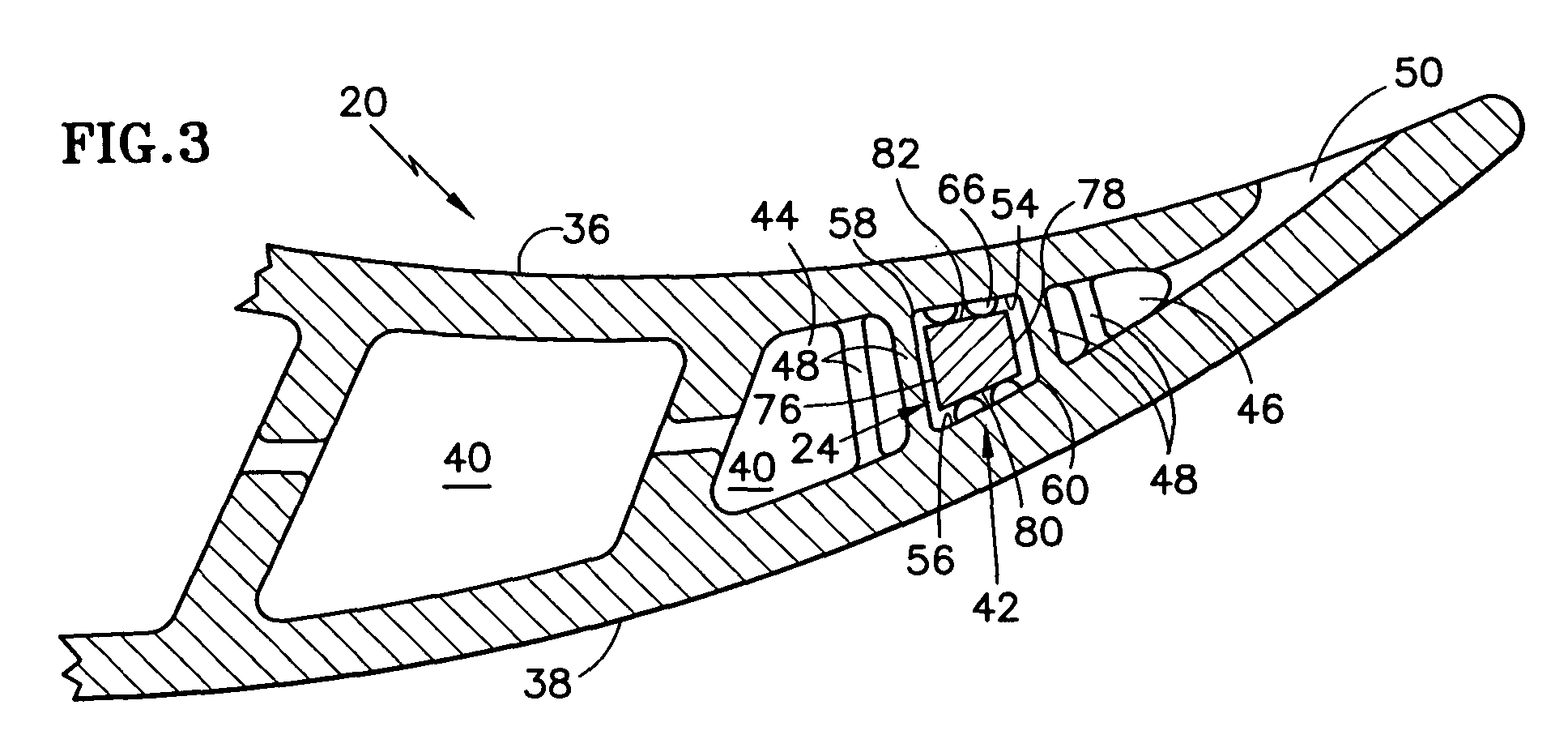
- FIG.3 is a diagrammatic section of a rotor blade portion.
- FIG.4 is a diagrammatic view of a portion of the first and second cavity portions and channel disposed therebetween, illustrating a first embodiment of raised features.
- FIG. 5 is an end view of the view shown in FIG.4.
- FIG. 6 is a diagrammatic view of a portion of the first and second cavity portions and channel disposed therebetween, illustrating a second embodiment of raised features.
- FIG.7 is an end view of the view shown in FIG.6.
- FIG. 8 is a perspective view of a damper embodiment.
-
- Referring to FIG. 1, a
rotor blade assembly 10 for a gas turbine engine is provided having adisk 12 and a plurality ofrotor blades 14. Thedisk 12 includes a plurality ofrecesses 16 circumferentially disposed around thedisk 12 and arotational centerline 17 about which thedisk 12 may rotate. Eachblade 14 includes aroot 18, anairfoil 20, aplatform 22, and a damper 24 (see FIG.2). Eachblade 14 also includes aradial centerline 25 passing through theblade 14, perpendicular to therotational centerline 17 of thedisk 12. Theroot 18 includes a geometry that mates with that of one of therecesses 16 within thedisk 12. A fir tree configuration is commonly known and may be used in this instance. As can be seen in FIG. 2, theroot 18 further includesconduits 26 through which cooling air may enter theroot 18 and pass through into theairfoil 20. - Referring to FIGS. 1-3, the
airfoil 20 includes abase 28, atip 30, a leadingedge 32, atrailing edge 34, apressure side wall 36, asuction side wall 38, acavity 40 disposed therebetween, and achannel 42. FIG.2 diagrammatically illustrates anairfoil 20 sectioned between the leadingedge 32 and thetrailing edge 34. Thepressure side wall 36 and thesuction side wall 38 extend between thebase 28 and thetip 30 and meet at the leadingedge 32 and thetrailing edge 34. Thecavity 40 can be described as having afirst cavity portion 44 forward of thechannel 42 and asecond cavity portion 46 aft of thechannel 42. In an embodiment where anairfoil 20 includes asingle cavity 40, thechannel 42 is disposed between portions of the onecavity 40. In an embodiment where anairfoil 20 includes more than onecavity 40, thechannel 42 may be disposed between adjacent cavities. To facilitate the description herein, thechannel 42 will be described herein as being disposed between afirst cavity portion 44 and asecond cavity portion 46, but is intended to include multiple cavity andsingle cavity airfoils 20 unless otherwise noted. In the embodiment shown in FIGS. 2-7, thesecond cavity portion 46 is proximate the trailingedge 34, and both thefirst cavity portion 44 and thesecond cavity portion 46 include a plurality ofpedestals 48 extending between the walls of theairfoil 20. The characteristics of a preferred pedestal arrangement are disclosed below. In alternative embodiments, only one or neither of the cavity portions contain pedestals 48. A plurality ofports 50 are disposed along theaft edge 52 of thesecond cavity portion 46, providing passages for cooling air to exit theairfoil 20 along the trailingedge 34. - The
channel 42 between the first andsecond cavity portions second wall portion 56 that extend lengthwise betweenbase 28 to tip 30, substantially the entire distance between the base 28 andtip 30. The channel initiates at anaperture 57 disposed within theroot side surface 59 of theplatform 22. Thechannel 42 has a first lengthwise extendingedge 58 and a second lengthwise extendingedge 60. The first lengthwise extendingedge 58 is disposed forward of the second lengthwise extendingedge 60. Thechannel 42 also includes awidth 62 that extends substantially perpendicular to the length 64 (i. e., axially), between the first and second lengthwise extendingedges channel 42 may extend substantially straight, or it may be arcuately shaped to accommodate an arcuately shaped damper as is shown in FIG.8. One or bothwall portions 54,56 include a plurality of raisedfeatures 66 that extend outwardly from the wall into thechannel 42. As will be explained below, the raised features 66 may have a geometry that enables them to form a point, line, or area contact with thedamper 24, or some combination thereof. Examples of the shapes that a raisedfeature 66 may assume include, but are not limited to, spherical, cylindrical, conical, or truncated versions thereof, of hybrids thereof. The distance that the raised features 66 extend outwardly into thechannel 42 may be uniform or may purposefully vary between raised features 66. - From a thermal perspective, a point contact is distinguished from an area contact by virtue of the point contact being a small enough area that heat transfer from cooling air passing the point contact cools the point contact to the extent that the temperature of the
damper 24 and theairfoil wall portion 54,56 at the point contact are not appreciably different from that of the surrounding area. A line contact is distinguished similarly; e.g., a line contact is distinguished from an area contact by virtue of the line contact being a small enough area that heat transfer from cooling air passing the line contact cools the line contact to the extent that the temperature of thedamper 24 and theairfoil wall portion 54,56 at the line contact is not appreciably different from that of the surrounding area. - From a damping perspective, a point contact is distinguished from an area contact by virtue of the magnitude of the load transmitted through the point contact versus through an area contact. Regardless of the size of the contact, the load for a given set of operating conditions will be the same and it will be distributed as a function of force per unit area. In the case of a plurality of point contacts, the load will be substantially higher per unit area than it would be for a much larger area contact relatively speaking. A line contact is distinguished similarly; e.g., a line contact is distinguished from an area contact by virtue of the line contact having a substantially higher per unit area than it would be for a much larger area contact relatively speaking.
- Referring to FIGS. 4-7, the size and the arrangement of the raised features 66 within the
channel 42 relative to the size of thechannel 42 are such thattortuous flow passages 68 are created across the width of thechannel 42. As a result, cooling air flow entering thechannel 42 across the first lengthwise extendingedge 58 encounters and passes a plurality of raisedfeatures 66 within thechannel 42 prior to exiting thechannel 42 across the second lengthwise extendingedge 60. The directional components of the cooling air flow within thetortuous flow passages 68 are discussed below. The raised features 66 within thechannel 42 may be arranged randomly and still form the aforesaid tortuous flow passages across the width of thechannel 42. The raised features 66 may also be arranged into rows, wherein the raised features 66 within one row are offset from the raised features 66 of an adjacent row to create the aforesaidtortuous flow path 68 between the pedestals 48. - With respect to the directional components of the cooling air flow within the
tortuous flow passages 68, substantially all of thetortuous flow passages 68 include at least one portion that extends at least partially in a lengthwise direction (shown as arrow "L") and at least one portion that extends at least partially in a widthwise direction (shown as arrow "W"). Thetortuous flow passages 68 desirably facilitate heat transfer between thedamper 24 and the cooling air, and between theairfoil wall portion 54,56 and the cooling air, for several reasons. For example, cooling air passing through thetortuous flow passages 68 has a longer dwell time between thedamper 24 and theairfoil wall portion 54,56 than cooling air typically would in a widthwise extending slot. Also, the surface area of thedamper 24 and theairfoil 20 exposed to the cooling air within thetortuous flow passages 68 is increased relative to that typically exposed within a prior art damper arrangement having widthwise extending slots. These cooling advantages are not available to damper having only widthwise extending slots and area contacts therebetween. - Referring to FIGS. 3 and 8, the
damper 24 includes ahead 70 and abody 72. Thebody 72 includes alength 74, aforward face 76, anaft face 78, and a pair of bearingsurfaces head 70, fixed to one end of thebody 72, may contain aseal surface 84 for sealing between thehead 70 and theblade 14. Thebody 72 is typically shaped in cross-section to mate with the cross-sectional shape of thechannel 42. For example, adamper 24 having a trapezoidal cross-sectional shape is preferably used with achannel 42 having trapezoidal cross-sectional shape. The cross-sectional area of thedamper 24 may change along itslength 74 to mate with the cross-sectional shape of thechannel 42 portion aligned therewith when thedamper 24 is installed within thechannel 42. The bearing surfaces 80,82 extend between theforward face 76 and theaft face 78, and along thelength 74 of thebody 72. - Referring to FIGS. 2-7, in preferred embodiments the
first cavity portion 44 and thesecond cavity portion 46 include a plurality ofpedestals 48 extending between the walls of theairfoil 20, proximate thechannel 42. Thepedestals 48, located within thefirst cavity portion 44 adjacent the first lengthwise extending edge of thechannel 42, are shown in FIGS. 2-5 as substantially cylindrical in shape.Other pedestal 48 shapes may be used alternatively. The plurality ofpedestals 48 within thefirst cavity portion 44 are preferably arranged in an array having a plurality of rows offset from one another to create atortuous flow path 88 between the pedestals 48. Thetortuous flow path 88 improves local heat transfer and promotes uniform flow distribution for the cooling air entering thechannel 42 across the first lengthwise extendingedge 58. The pedestal array can be disposed along a portion or all of the length of thechannel 42. - The
pedestals 48 within thesecond cavity portion 46 may assume a variety of different shapes; e.g., cylindrical, oval, etc., and are located adjacent the second lengthwise extendingedge 60 of thechannel 42. In the embodiments shown in FIGS. 4 7, eachpedestal 48 includes aconvergent portion 86 that extends out in an aftward direction; e.g., a teardrop shapedpedestal 48 with theconvergent portion 86 of the teardrop oriented toward the trailingedge 34. Cooling air flow traveling in the direction forward to aft past the aft-positionedconvergent portion 86 forms a smaller wake than would similar flow traveling past, for example, a circular shapedpedestal 48. The decreased wakes provide desirable flow characteristics entering the trailingedge ports 50. The plurality ofpedestals 48 within thesecond cavity portion 46 are preferably arranged in an array having a plurality of rows offset from one another to create atortuous flow path 90 between the pedestals 48. Thetortuous flow path 90 improves local heat transfer and promotes uniform flow distribution for the cooling air exiting the channel 42across the second lengthwise extendingedge 60. The pedestal array can be disposed along a portion or all of the length of thechannel 42. The aft-most row is located so that thepedestals 48 contained therein are aligned relative to the cooling features of the trailingedge 34. For example, thepedestals 48 within the aft-most row shown in FIGS. 47 are aligned with theports 50 disposed along the trailingedge 34. - Referring to FIGS. 1-8, under steady-state operating conditions, a
rotor blade assembly 10 within a gas turbine engine rotates through core gas flow passing through the engine. The high temperature core gas flow impinges on theblades 14 of therotor blade assembly 10 and transfers a considerable amount of thermal energy to eachblade 14, usually in a non-uniform manner. To dissipate some of the thermal energy, cooling air is passed into theconduits 26 within theroot 18 of each blade. From there, a portion of the cooling air passes into thefirst cavity portion 44 where pressure differences direct it toward and into the array ofpedestals 48 adjacent the first lengthwise extendingedge 58 of thechannel 42. From there the cooling air crosses the first lengthwise extendingedge 58 of thechannel 42 are enters thetortuous flow passages 68 formed between theairfoil wall portion 54,56, thedamper 24, and pedestals 48 extending therebetween. Substantially all of thetortuous flow passages 68 include at least a portion that extends at least partially in a lengthwise direction and at least a portion that extends at least partially in a widthwise direction. As a result, cooling air within thetortuous flow passages 68 distributes lengthwise as it travels across the width of thedamper 24. Once the cooling air has traveled across the width of thedamper 24, it exits thepassages 68, crosses the second lengthwise extendingedge 60 of thechannel 42, and enters the array ofpedestals 48 adjacent the second lengthwise extendingedge 60 of thechannel 42. Once the flow passes through the array ofpedestals 48 adjacent the second lengthwise extendingedge 60 of thechannel 42, it exits theports 50 disposed along the trailingedge 34 of theairfoil 20. - The bearing surfaces 80,82 of the
damper 24 contact the raised features 66 extending out from thewall portions 54,56 of thechannel 42. Depending upon the internal characteristics of theairfoil 20, thedamper 24 may be forced into contact with the raised features 66 by a pressure difference across thechannel 42. A contact force is further effectuated by centrifugal forces acting on thedamper 24, created as thedisk 12 of therotor blade assembly 10 is rotated about itsrotational centerline 17. The skew of thechannel 42 relative to the radial centerline of theblade 25, and thedamper 24 received within thechannel 42, causes a component of the centrifugal force acting on thedamper 24 to act in the direction of thewall portions 54,56 of thechannel 42; i.e., the centrifugal force component acts as a normal force against thedamper 24 in the direction of thewall portions 54,56 of thechannel 42. - Although this invention has been shown and described with respect to the detailed embodiments thereof, it will be understood by those skilled in the art that various changes in form and detail thereof may be made without departing from the scope of the invention.
Claims (12)
- A rotor blade (14) for a rotor assembly (10), comprising:a root (18);an airfoil (20), having a base (28), a tip (30), a pressure side wall (36), a suction side wall (38), a cavity (40) disposed between the side walls (36, 38), and a channel (42) disposed within the cavity (40), wherein at least a portion of one of the pressure side wall (36) and suction side wall (38) aligned with the channel (42) includes a plurality of raised features (66) extending outwardly from the wall into the channel (42), and the raised features (66) are separated from one another to create passages (68) therebetween; anda damper (24), selectively received within the channel (42); andwherein at least some of the passages (68) between the raised features (66) include a flow direction that includes a lengthwise component and a widthwise component.
- The rotor blade of claim 1, wherein the plurality of raised features (66) are arranged to form a tortuous flow path for cooling air entering the channel (42) across a first lengthwise extending edge (58) and exiting the channel (42) across a second lengthwise extending edge (60), wherein the second lengthwise extending edge (60) is aft of the first lengthwise extending edge (58).
- A rotor blade (14) for a rotor assembly (10), comprising:a root (18);an airfoil (20), having a base (28), a tip (30), a pressure side wall (36), a suction side wall (38), a cavity (40) disposed between the side walls (36, 38), and a channel (42) disposed within the cavity (40), wherein at least a portion of one of the pressure side wall (36) and suction side wall (38) aligned with the channel (42) includes a plurality of raised features (66) extending outwardly from thewall into the channel (42), and the raised features (66) are separated from one another to create passages (68) therebetween; anda damper (24) , selectively received within the channel (42); andwherein the plurality of raised features (66) are arranged to form a tortuous flow path for cooling air entering the channel (42) across a first lengthwise extending edge (58) and exiting the channel (42) across a second lengthwise extending edge (60), wherein the second lengthwise extending edge (60) is aft ofthe first lengthwise extending edge (58).
- The rotor blade of any preceding claim, wherein at least some of the raised features (66) make a point contact with the damper (24).
- The rotor blade of claim 4, wherein the at least some of the raised features (66) are spherically shaped.
- The rotor blade of any preceding claim, wherein at least some of the raised features (66) make a line contact with the damper (24).
- The rotor blade of claim 6, wherein the at least some of the raised features (66) are cylindrically shaped.
- The rotor blade of any preceding claim, wherein the plurality of raised features (66) are randomly arranged.
- The rotor blade of any of claims 1 to 7, wherein the plurality of raised features (66) are arranged in a plurality of rows, and the raised features (66) within each row are positioned offset from the raised features (66) within an adjacent row of raised features.
- The rotor blade of any preceding claim, wherein the damper (24) further comprises:a forward face (76);an aft face (78); anda pair of bearing surfaces (80, 82), extending between the forward and aft faces (76, 78).
- The rotor blade of claim 10, further comprising:a platform (22), extending laterally outward from the blade (14) between the root (18) and the airfoil (20) , the platform (22) having an airfoil side and a root side, and an aperture (57) extending between the root side (59) of the platform and the cavity (40); andwherein the damper (24) is received within the aperture (57) and extends into the channel (42).
- The rotor blade of any preceding claim, wherein the airfoil (20) further comprises a leading edge (32) and a trailing edge (34), wherein the damper (24) is received within the airfoil (20) adjacent the trailing edge (34).
Applications Claiming Priority (2)
| Application Number | Priority Date | Filing Date | Title |
|---|---|---|---|
| US741103 | 1991-08-06 | ||
| US10/741,103 US7033140B2 (en) | 2003-12-19 | 2003-12-19 | Cooled rotor blade with vibration damping device |
Publications (3)
| Publication Number | Publication Date |
|---|---|
| EP1544412A2 true EP1544412A2 (en) | 2005-06-22 |
| EP1544412A3 EP1544412A3 (en) | 2008-11-26 |
| EP1544412B1 EP1544412B1 (en) | 2013-04-17 |
Family
ID=34523218
Family Applications (1)
| Application Number | Title | Priority Date | Filing Date |
|---|---|---|---|
| EP04257901.1A Expired - Fee Related EP1544412B1 (en) | 2003-12-19 | 2004-12-17 | Cooled rotor blade with vibration damping device |
Country Status (10)
| Country | Link |
|---|---|
| US (1) | US7033140B2 (en) |
| EP (1) | EP1544412B1 (en) |
| JP (1) | JP4035129B2 (en) |
| KR (1) | KR100701546B1 (en) |
| AU (1) | AU2004240222B2 (en) |
| CA (1) | CA2486837A1 (en) |
| IL (1) | IL165472A0 (en) |
| NO (1) | NO20045502L (en) |
| SG (1) | SG112990A1 (en) |
| TW (1) | TWI254767B (en) |
Cited By (1)
| Publication number | Priority date | Publication date | Assignee | Title |
|---|---|---|---|---|
| EP1980716A3 (en) * | 2007-04-10 | 2012-08-01 | General Electric Company | Damper configured turbine blade |
Families Citing this family (13)
| Publication number | Priority date | Publication date | Assignee | Title |
|---|---|---|---|---|
| US8016561B2 (en) * | 2006-07-11 | 2011-09-13 | General Electric Company | Gas turbine engine fan assembly and method for assembling to same |
| US9133715B2 (en) * | 2006-09-20 | 2015-09-15 | United Technologies Corporation | Structural members in a pedestal array |
| US8807945B2 (en) * | 2011-06-22 | 2014-08-19 | United Technologies Corporation | Cooling system for turbine airfoil including ice-cream-cone-shaped pedestals |
| US9249668B2 (en) * | 2012-04-24 | 2016-02-02 | United Technologies Corporation | Airfoil with break-way, free-floating damper member |
| US8951004B2 (en) * | 2012-10-23 | 2015-02-10 | Siemens Aktiengesellschaft | Cooling arrangement for a gas turbine component |
| US20170175532A1 (en) * | 2015-12-21 | 2017-06-22 | United Technologies Corporation | Angled heat transfer pedestal |
| US10337332B2 (en) * | 2016-02-25 | 2019-07-02 | United Technologies Corporation | Airfoil having pedestals in trailing edge cavity |
| US10436048B2 (en) * | 2016-08-12 | 2019-10-08 | General Electric Comapny | Systems for removing heat from turbine components |
| US10830072B2 (en) * | 2017-07-24 | 2020-11-10 | General Electric Company | Turbomachine airfoil |
| FR3094033B1 (en) * | 2019-03-22 | 2021-06-11 | Safran Aircraft Engines | TURBOMACHINE BLADE EQUIPPED WITH AN OPTIMIZED COOLING CIRCUIT |
| CN115182888B (en) * | 2022-08-15 | 2024-08-09 | 常州市东南电器电机有限公司 | Electronic water pump with waterproof and damping structure |
| JP2025006946A (en) * | 2023-06-30 | 2025-01-17 | ダイキン工業株式会社 | Method for manufacturing porous member, fan, and component |
| CN119737337B (en) * | 2024-12-19 | 2026-01-13 | 华电湖北发电有限公司武昌热电分公司 | A compressor blade with a venturi tube microchannel cooling structure |
Citations (1)
| Publication number | Priority date | Publication date | Assignee | Title |
|---|---|---|---|---|
| US5558497A (en) | 1995-07-31 | 1996-09-24 | United Technologies Corporation | Airfoil vibration damping device |
Family Cites Families (11)
| Publication number | Priority date | Publication date | Assignee | Title |
|---|---|---|---|---|
| US3966357A (en) * | 1974-09-25 | 1976-06-29 | General Electric Company | Blade baffle damper |
| US4257734A (en) | 1978-03-22 | 1981-03-24 | Rolls-Royce Limited | Guide vanes for gas turbine engines |
| DE3629910A1 (en) | 1986-09-03 | 1988-03-17 | Mtu Muenchen Gmbh | METAL HOLLOW COMPONENT WITH A METAL INSERT, IN PARTICULAR TURBINE BLADE WITH COOLING INSERT |
| US5288207A (en) | 1992-11-24 | 1994-02-22 | United Technologies Corporation | Internally cooled turbine airfoil |
| US5516260A (en) * | 1994-10-07 | 1996-05-14 | General Electric Company | Bonded turbine airfuel with floating wall cooling insert |
| US5820343A (en) * | 1995-07-31 | 1998-10-13 | United Technologies Corporation | Airfoil vibration damping device |
| US5738493A (en) * | 1997-01-03 | 1998-04-14 | General Electric Company | Turbulator configuration for cooling passages of an airfoil in a gas turbine engine |
| JP3897402B2 (en) | 1997-06-13 | 2007-03-22 | 三菱重工業株式会社 | Gas turbine stationary blade insert insertion structure and method |
| US6468669B1 (en) * | 1999-05-03 | 2002-10-22 | General Electric Company | Article having turbulation and method of providing turbulation on an article |
| US6402470B1 (en) * | 1999-10-05 | 2002-06-11 | United Technologies Corporation | Method and apparatus for cooling a wall within a gas turbine engine |
| EP1188902A1 (en) * | 2000-09-14 | 2002-03-20 | Siemens Aktiengesellschaft | Impingement cooled wall |
-
2003
- 2003-12-19 US US10/741,103 patent/US7033140B2/en not_active Expired - Lifetime
-
2004
- 2004-11-05 CA CA002486837A patent/CA2486837A1/en not_active Abandoned
- 2004-11-22 TW TW093135896A patent/TWI254767B/en not_active IP Right Cessation
- 2004-11-30 IL IL16547204A patent/IL165472A0/en unknown
- 2004-12-03 KR KR1020040100733A patent/KR100701546B1/en not_active Expired - Fee Related
- 2004-12-09 JP JP2004357452A patent/JP4035129B2/en not_active Expired - Fee Related
- 2004-12-16 NO NO20045502A patent/NO20045502L/en not_active Application Discontinuation
- 2004-12-17 SG SG200407504A patent/SG112990A1/en unknown
- 2004-12-17 EP EP04257901.1A patent/EP1544412B1/en not_active Expired - Fee Related
- 2004-12-17 AU AU2004240222A patent/AU2004240222B2/en not_active Ceased
Patent Citations (1)
| Publication number | Priority date | Publication date | Assignee | Title |
|---|---|---|---|---|
| US5558497A (en) | 1995-07-31 | 1996-09-24 | United Technologies Corporation | Airfoil vibration damping device |
Cited By (1)
| Publication number | Priority date | Publication date | Assignee | Title |
|---|---|---|---|---|
| EP1980716A3 (en) * | 2007-04-10 | 2012-08-01 | General Electric Company | Damper configured turbine blade |
Also Published As
| Publication number | Publication date |
|---|---|
| TW200523458A (en) | 2005-07-16 |
| US20050135935A1 (en) | 2005-06-23 |
| JP4035129B2 (en) | 2008-01-16 |
| KR20050062374A (en) | 2005-06-23 |
| SG112990A1 (en) | 2005-07-28 |
| CA2486837A1 (en) | 2005-06-19 |
| TWI254767B (en) | 2006-05-11 |
| EP1544412A3 (en) | 2008-11-26 |
| KR100701546B1 (en) | 2007-03-30 |
| AU2004240222B2 (en) | 2007-02-08 |
| IL165472A0 (en) | 2006-01-15 |
| US7033140B2 (en) | 2006-04-25 |
| AU2004240222A1 (en) | 2005-07-07 |
| NO20045502L (en) | 2005-06-20 |
| EP1544412B1 (en) | 2013-04-17 |
| JP2005180429A (en) | 2005-07-07 |
Similar Documents
| Publication | Publication Date | Title |
|---|---|---|
| EP1561901B1 (en) | Vibration damping device for cooled blades in a turbine rotor | |
| EP1544413B1 (en) | Cooled rotor blade with vibration damping device | |
| EP1564375B1 (en) | Cooled rotor blade with vibration damping device | |
| EP0757160B1 (en) | Airfoil vibration damping device | |
| CN101550843B (en) | Gas turbine airfoil | |
| EP1602801B1 (en) | Rotor blade with a stick damper | |
| EP1544412B1 (en) | Cooled rotor blade with vibration damping device | |
| AU2004240227B2 (en) | Cooled rotor blade with vibration damping device |
Legal Events
| Date | Code | Title | Description |
|---|---|---|---|
| PUAI | Public reference made under article 153(3) epc to a published international application that has entered the european phase |
Free format text: ORIGINAL CODE: 0009012 |
|
| AK | Designated contracting states |
Kind code of ref document: A2 Designated state(s): AT BE BG CH CY CZ DE DK EE ES FI FR GB GR HU IE IS IT LI LT LU MC NL PL PT RO SE SI SK TR |
|
| AX | Request for extension of the european patent |
Extension state: AL BA HR LV MK YU |
|
| PUAL | Search report despatched |
Free format text: ORIGINAL CODE: 0009013 |
|
| AK | Designated contracting states |
Kind code of ref document: A3 Designated state(s): AT BE BG CH CY CZ DE DK EE ES FI FR GB GR HU IE IS IT LI LT LU MC NL PL PT RO SE SI SK TR |
|
| AX | Request for extension of the european patent |
Extension state: AL BA HR LV MK YU |
|
| RIC1 | Information provided on ipc code assigned before grant |
Ipc: F01D 5/18 20060101ALI20081022BHEP Ipc: F01D 5/26 20060101ALI20081022BHEP Ipc: F01D 5/16 20060101AFI20050216BHEP |
|
| 17P | Request for examination filed |
Effective date: 20090518 |
|
| AKX | Designation fees paid |
Designated state(s): DE GB |
|
| 17Q | First examination report despatched |
Effective date: 20111223 |
|
| GRAP | Despatch of communication of intention to grant a patent |
Free format text: ORIGINAL CODE: EPIDOSNIGR1 |
|
| GRAS | Grant fee paid |
Free format text: ORIGINAL CODE: EPIDOSNIGR3 |
|
| GRAA | (expected) grant |
Free format text: ORIGINAL CODE: 0009210 |
|
| AK | Designated contracting states |
Kind code of ref document: B1 Designated state(s): DE GB |
|
| REG | Reference to a national code |
Ref country code: GB Ref legal event code: FG4D Ref country code: DE Ref legal event code: R081 Ref document number: 602004041765 Country of ref document: DE Owner name: UNITED TECHNOLOGIES CORP. (N.D.GES.D. STAATES , US Free format text: FORMER OWNER: UNITED TECHNOLOGIES CORP. (N.D.GES.D. STAATES DELAWARE), HARTFORD, CONN., US |
|
| REG | Reference to a national code |
Ref country code: DE Ref legal event code: R096 Ref document number: 602004041765 Country of ref document: DE Effective date: 20130606 |
|
| PLBE | No opposition filed within time limit |
Free format text: ORIGINAL CODE: 0009261 |
|
| STAA | Information on the status of an ep patent application or granted ep patent |
Free format text: STATUS: NO OPPOSITION FILED WITHIN TIME LIMIT |
|
| 26N | No opposition filed |
Effective date: 20140120 |
|
| REG | Reference to a national code |
Ref country code: DE Ref legal event code: R097 Ref document number: 602004041765 Country of ref document: DE Effective date: 20140120 |
|
| REG | Reference to a national code |
Ref country code: DE Ref legal event code: R082 Ref document number: 602004041765 Country of ref document: DE Representative=s name: SCHMITT-NILSON SCHRAUD WAIBEL WOHLFROM PATENTA, DE |
|
| REG | Reference to a national code |
Ref country code: DE Ref legal event code: R082 Ref document number: 602004041765 Country of ref document: DE Representative=s name: SCHMITT-NILSON SCHRAUD WAIBEL WOHLFROM PATENTA, DE Ref country code: DE Ref legal event code: R081 Ref document number: 602004041765 Country of ref document: DE Owner name: UNITED TECHNOLOGIES CORP. (N.D.GES.D. STAATES , US Free format text: FORMER OWNER: UNITED TECHNOLOGIES CORPORATION, HARTFORD, CONN., US |
|
| PGFP | Annual fee paid to national office [announced via postgrant information from national office to epo] |
Ref country code: DE Payment date: 20191119 Year of fee payment: 16 |
|
| PGFP | Annual fee paid to national office [announced via postgrant information from national office to epo] |
Ref country code: GB Payment date: 20191122 Year of fee payment: 16 |
|
| REG | Reference to a national code |
Ref country code: DE Ref legal event code: R119 Ref document number: 602004041765 Country of ref document: DE |
|
| GBPC | Gb: european patent ceased through non-payment of renewal fee |
Effective date: 20201217 |
|
| PG25 | Lapsed in a contracting state [announced via postgrant information from national office to epo] |
Ref country code: DE Free format text: LAPSE BECAUSE OF NON-PAYMENT OF DUE FEES Effective date: 20210701 Ref country code: GB Free format text: LAPSE BECAUSE OF NON-PAYMENT OF DUE FEES Effective date: 20201217 |