EP1544341A2 - Washing machine with drying function - Google Patents
Washing machine with drying function Download PDFInfo
- Publication number
- EP1544341A2 EP1544341A2 EP04029989A EP04029989A EP1544341A2 EP 1544341 A2 EP1544341 A2 EP 1544341A2 EP 04029989 A EP04029989 A EP 04029989A EP 04029989 A EP04029989 A EP 04029989A EP 1544341 A2 EP1544341 A2 EP 1544341A2
- Authority
- EP
- European Patent Office
- Prior art keywords
- duct
- tub
- washing machine
- heater
- set forth
- Prior art date
- Legal status (The legal status is an assumption and is not a legal conclusion. Google has not performed a legal analysis and makes no representation as to the accuracy of the status listed.)
- Granted
Links
- 238000001035 drying Methods 0.000 title claims abstract description 124
- 238000005406 washing Methods 0.000 title claims abstract description 116
- 238000004891 communication Methods 0.000 claims description 35
- 238000007664 blowing Methods 0.000 claims description 30
- 239000000463 material Substances 0.000 claims description 18
- XAGFODPZIPBFFR-UHFFFAOYSA-N aluminium Chemical compound [Al] XAGFODPZIPBFFR-UHFFFAOYSA-N 0.000 claims description 10
- 229910052782 aluminium Inorganic materials 0.000 claims description 10
- 238000004512 die casting Methods 0.000 claims description 9
- 238000003825 pressing Methods 0.000 claims description 9
- 238000007789 sealing Methods 0.000 claims description 9
- XLYOFNOQVPJJNP-UHFFFAOYSA-N water Substances O XLYOFNOQVPJJNP-UHFFFAOYSA-N 0.000 description 43
- 239000000498 cooling water Substances 0.000 description 27
- 230000000694 effects Effects 0.000 description 15
- 239000011521 glass Substances 0.000 description 6
- 239000003599 detergent Substances 0.000 description 4
- 238000004519 manufacturing process Methods 0.000 description 4
- 238000010276 construction Methods 0.000 description 3
- 238000002347 injection Methods 0.000 description 3
- 239000007924 injection Substances 0.000 description 3
- 239000000356 contaminant Substances 0.000 description 2
- 238000007599 discharging Methods 0.000 description 2
- 238000010981 drying operation Methods 0.000 description 2
- 238000007792 addition Methods 0.000 description 1
- 238000010438 heat treatment Methods 0.000 description 1
- 238000012986 modification Methods 0.000 description 1
- 230000004048 modification Effects 0.000 description 1
- 230000000149 penetrating effect Effects 0.000 description 1
- 238000005086 pumping Methods 0.000 description 1
- 230000035939 shock Effects 0.000 description 1
- 238000006467 substitution reaction Methods 0.000 description 1
Images


Classifications
-
- D—TEXTILES; PAPER
- D06—TREATMENT OF TEXTILES OR THE LIKE; LAUNDERING; FLEXIBLE MATERIALS NOT OTHERWISE PROVIDED FOR
- D06F—LAUNDERING, DRYING, IRONING, PRESSING OR FOLDING TEXTILE ARTICLES
- D06F25/00—Washing machines with receptacles, e.g. perforated, having a rotary movement, e.g. oscillatory movement, the receptacle serving both for washing and for centrifugally separating water from the laundry and having further drying means, e.g. using hot air
Definitions
- the present invention relates to a washing machine with drying function, and, more particularly, to a washing machine with drying function that is capable of directly supplying air, heated while passing through a heater duct, into a tub not through a gasket.
- a laundry machine is a machine that removes contaminants from clothes or bedclothes (hereinafter, referred to as “the laundry") with a detergent and water (hereinafter, referred to as “wash water”).
- the laundry machine may be generally classified into a washing machine that only washes the laundry, a drying machine that only dries the laundry, and a washing machine with drying function that washes and dries the laundry.
- FIG. 1 is a side sectional view, cutaway in part, illustrating the inner structure of a conventional washing machine with drying function.
- the conventional washing machine with drying function comprises: a cabinet 2; a tub 10 mounted in the cabinet 2 for receiving wash water; a drum 20 rotatably disposed in the tub for receiving the laundry m; a motor 30 for rotating the drum while supporting the drum 20; and a drying unit 40 for drawing air out of the drum 20, condensing and heating the drawn air, and supplying the condensed and heated air into the drum 20 to dry the laundry m.
- the cabinet 2 is provided at one side thereof with an inlet/outlet hole 3 for allowing the laundry m to be put into or taken out of the cabinet 2 therethrough.
- a door 4 for opening and closing the inlet/outlet hole 3.
- the door 4 comprises: a doorframe 4a hingedly connected to the cabinet 2; and a door glass 4b attached to the doorframe 4a.
- the door glass 4b is formed such that the door glass 4b is convex toward the rear of the door glass 4b.
- the tub 10 is connected to a spring 5, which is connected to the top part of the cabinet 2, while the tub 10 is suspended by the spring 5. Also, the tub 10 is laid on a damper mounted to the bottom part of the cabinet 2, while the tub 10 is supported by the damper 6, such that shock applied to the tub 10 is absorbed by the damper 6.
- a water-supply unit 12 for supplying wash water, which is supplied from the outside of the washing machine, into the tub 10.
- a drainage unit 14 for draining wash water in the tub 10 out of the washing machine.
- a gasket 16 which is closely coupled to the door 4, when the door 4 is closed, for preventing the laundry m, wash water, and air from flowing out of the space between the door 4 and the tub 10.
- the drying unit connection member 18 is formed at the outer circumferential part of the gasket 16 while being protruded in the radial direction of the gasket 16.
- the drum 20 is provided with an inlet/outlet hole 21 for allowing the laundry m, wash water, and air to be introduced into and taken out of the drum 20 therethrough, and through-holes 22 for allowing wash water and air to be introduced into and discharged out of the drum 20 therethrough.
- the motor 30 is supported by the tub 10 through a bearing disposed between the motor 30 and the tub 10 while a rotary shaft of the motor 30 penetrates the tub 10. The end of the motor is connected to the drum 20.
- the drying unit 40 comprises: a condensing duct 42 connected to one side of the tub 10; a cooling water valve 43 for allowing cooling water to flow therethrough or stopping the cooling water from flowing therethrough; a cooling water injection member 44 connected to the cooling water valve 43 for injecting cooling water into the condensing duct 42; and a heater duct 48 communicating with the condensing duct 42 and having a circulating fan 45 and a heater 46 mounted therein for supplying high-temperature and low-humidity air into the drum 20.
- the heater duct 48 has an outlet fixedly connected to the drying unit connection member 18 of the gasket 16 in such a manner that the outlet of the heater duct 48 is inserted in or fitted on the drying unit connection member 18.
- wash water is supplied to the washing machine through the water-supply unit 12.
- the supplied wash water is introduced into the tub 10 such that the wash water is filled in the tub 10, and is also introduced into the drum 20 through the inlet/outlet hole 21 or the through-holes 22 of the drum 20 such that the laundry m is wetted by the wash water.
- the contaminated wash water in the tub 10 is drained out of the washing machine through the drainage unit 14.
- the water-supply unit 12 and the motor 30 are controlled to rinse out the bubbles left in the laundry as in the washing operation, and the contaminated water, including the bubbles, is drained out of the washing machine through the drainage unit 14.
- the dewatering operation is carried out for centrifugally separating moisture from the laundry m.
- the drying unit 40 is operated to dry the laundry m.
- the motor 30 is driven to rotate the drum 20, and the cooling water valve 43, the circulating fan 45, and the heater 46 are turned on. In this way, the drying operation of the washing machine is carried out.
- the cooling water valve 43 As the cooling water valve 43 is opened, the cooling water is injected into the condensing duct 42. As the circulating fan 45 is rotated, low-temperature and high-humidity air in the drum 20 is introduced into the condensing duct 42 through the tub 10. The air is condensed by the cooling water while passing through the condensing duct 42.
- the air having passed through the condensing duct 42 is guided through the heater duct 48. At this time, the air is heated by the heater 46, and therefore the air is changed into hot wind.
- the hot wind passes through the drying unit connection member 18 of the gasket 16, is guided to the inside of the gasket 16, strikes the door glass 4b of the door 4, and is then blown toward the drum 20 such that the laundry is dried by the blown hot wind. As a result, the hot wind is changed into low-temperature and high-humidity air.
- the drying unit 40 is connected to the gasket 16. Consequently, the structure of the gasket 16 is complicated. Also, the hot wind passes through the gasket 16, strikes the door glass 4b of the door 4, and is then blown toward the laundry m. Consequently, the hot wind introduction channel is complicated, and therefore, flow and heat loss of the hot wind is large.
- the gasket 16 may be deformed due to vibration of the tub 10 or the drum 20.
- the hot wind introduction channel is deformed or blocked due to the deformation of the gasket 16, it is difficult to introduce the hot wind having passed through the heater duct 48 into the drum 20.
- the gasket 16 may be damaged due to the hot wind.
- a washing machine with drying function comprising: a tub disposed in a cabinet while being supported; a drum rotatably disposed inside the tub, the drum being provided with through-holes; a condensing duct communicating with one side of the tub; and a drying duct communicating with the condensing duct, the drying duct having a heater and a blowing fan mounted therein, the drying duct communicating with the other side of the tub.
- the tub is provided at one side thereof with a first communication hole communicating with the condensing duct, and at the other side thereof with a second communication hole communicating with the drying duct.
- the first communication hole is formed at a rear part of the tub.
- the second communication hole is formed at a front part of the tub.
- the second communication hole is formed at an upper position of the front part of the tub.
- the second communication hole is formed at a circumferential part of the tub.
- the drying duct comprises: a heater duct having one end communicating with the condensing duct, the heater duct having the heater and the blowing fan mounted therein; and a connection duct having one end communicating with the heater duct and the other end communicating with the second communication hole of the tub.
- the washing machine with drying function further comprises: a heater duct gasket disposed between the heater duct and the connection duct for sealing a space between the heater duct and the connection duct.
- the washing machine with drying function further comprises: a tub gasket disposed between the connection duct and the tub for sealing a space between the connection duct and the tub.
- the washing machine with drying function further comprises: a fan motor, to which the blowing fan is connected via a shaft
- the heater duct comprises: a duct body attached to the tub, the duct body having an open upper part, the duct body having the heater and the blowing fan disposed therein, the duct body being manufactured through die casting of an aluminum material; and an upper cover disposed to cover the open upper part of the duct body, the upper cover being provided with a fan motor location part corresponding to the blowing fan, the upper cover being manufactured by pressing a stainless material.
- the washing machine with drying function further comprises: a motor mounted to the heater duct; a driving pulley connected to the motor via a shaft; a driven pulley connected to the blowing fan via a shaft; and a belt wound on the driving pulley and the driven pulley
- the heater duct comprises: a duct body attached to the tub, the duct body having an open upper part, the duct body having the heater and the blowing fan disposed therein, the duct body being manufactured through die casting of an aluminum material; and an upper cover disposed to cover the open upper part of the duct body, the upper cover being provided with a driven pulley location part corresponding to the blowing fan, the upper cover being manufactured by pressing a stainless material.
- connection duct is fixed to the tub by means of fixing bolts.
- the tub is provided with bosses, and the connection duct is fixed to the bosses by means of the fixing bolts.
- connection duct is provided with a stepped end, the stepped end being inserted in the second communication hole of the tub.
- connection duct is fixed to the heater duct by means of fixing bolts.
- the drum is provided at a front part thereof with a plurality of hot wind through-holes for introducing hot wind having passed through the second communication hole of the tub into the drum.
- the washing machine with drying function of the present invention has an effect in that hot wind heated while passing through the drying duct is directly supplied into the tub, whereby flow and heat loss of the hot wind is minimized, and thus, the drying performance of the washing machine with drying function is improved.
- the washing machine with drying function of the present invention has an effect in that the heater duct, which has the heater and the blowing fan mounted therein, communicates with the condensing duct, and the connection duct, which guides air having passed through the heater duct into the tub, communicates with the heater duct and the tub, whereby flow and heat loss of the hot wind is minimized, and thus, the drying performance of the washing machine with drying function is improved.
- the washing machine with drying function of the present invention has an effect in that air having passed through the heater duct is guided along the connection duct, not through the gasket, whereby damage to the gasket, which may be caused when the air having passed the heater duct is guided through the gasket, is prevented, and thus, the service life of the gasket is prevented from being shortened.
- the washing machine with drying function of the present invention has an effect in that the heater duct gasket is disposed between the heater duct and the connection duct, and the tub gasket is disposed between the connection duct and the tub, whereby outflow of hot wind is minimized.
- connection duct is fixed to the upper position of the front part of the tub by means of the fixing bolts, and the connection duct is also fixed to the lower end of the heater duct by means of the fixing bolts, whereby easy and convenient fixing of the connection duct is accomplished.
- the washing machine with drying function of the present invention has an effect in that a plurality of hot wind through-holes are formed at the drum such that hot wind having passed through the connection duct can be directly guided into the drum, whereby the smooth flow of air is accomplished, and thus, the drying performance of the washing machine with drying function is improved.
- the washing machine with drying function of the present invention has an effect in that the heater duct comprises the duct body having the open upper part and manufactured through die casting of an aluminum material, and the upper cover disposed to cover the open upper part of the duct body and manufactured by pressing a stainless material such that the upper cover can be flexibly adapted to the duct body although the shape and the length of the duct body are changed, whereby the manufacturing costs and the weight of the heater duct are reduced, and thus, the productivity of the heater duct is improved.
- FIG. 2 is a side view, in section, illustrating a washing machine with drying function according to a first preferred embodiment of the present invention
- FIG. 3 is a perspective view, cutaway in part, illustrating the washing machine with drying function according to the first preferred embodiment of the present invention.
- the washing machine with drying function comprises: a cabinet 50 forming the external appearance of the washing machine; a tub 60 disposed in the cabinet 50 while being supported in a shock-absorbing fashion; a drum 70 rotatably disposed inside the tub 60 for receiving the laundry; a condensing duct 80 communicating with one side of the tub 60; and a drying duct 86 communicating with the condensing duct 80, the drying duct 86 having a heater 85 and a blowing fan 87 mounted therein, the drying duct 86 communicating with the other side of the tub 60 for directly guiding air heated by the heater 85 into the tub 60.
- the cabinet 50 comprises: a base pan 52; a cabinet body 54 fixedly disposed on the base pan 52; a cabinet cover 56 attached to the front part of the cabinet body 54; and a top cover 58 fixedly disposed on the top part of the cabinet body 54.
- the cabinet cover 56 is provided with a laundry inlet/outlet hole 56a for allowing the laundry to be put into or taken out of the cabinet 50 therethrough.
- a door 56b for opening and closing the laundry inlet/outlet hole 56a.
- control panel 59 for controlling the washing machine with drying function.
- the tub 60 is formed in the shape of a cylinder that is disposed horizontally or at a slope of predetermined degrees.
- the tub 60 is provided with an opening hole 61a, which is disposed at the rear of the laundry inlet/outlet hole 56a.
- the tub 60 is connected to the cabinet body 54 by springs 61b.
- the tub 60 is also connected to the base pan 52 by a damper 61c.
- a water-supply unit 62 for supplying wash water into the tub 60.
- a drainage unit 63 for draining contaminated wash water or water separated from the laundry m out of the washing machine.
- the water-supply unit 62 comprises: a water-supply valve 62b connected to an external hose 62a for allowing wash water supplied from the external hose 62a to flow therethrough or stopping the wash water from flowing therethrough; a water-supply hose 62c for guiding the wash water having passed through the water-supply valve 62b; a detergent box 62d disposed such that the wash water guided along the water-supply hose 62c passes through the detergent box 62d; and a water-supply bellows 62e for guiding the wash water having passed through the detergent box 62d into the tub 60.
- the drainage unit 63 comprises: a drainage bellows 63a connected to the tub 60 for guiding wash water or water from the tub 60 to a drainage pump 63b therealong; the drainage pump 63b for pumping out the wash water or the water guided along the drainage bellows 63a; and a drainage hose 63c for guiding the wash water or the water pumped out by the drainage pump 63b out of the washing machine with drying function.
- the tub 60 is provided with a first communication hole 64a communicating with the condensing duct 80 for discharging air from the tub 60 to the condensing duct 80.
- the tub 60 is also provided with a second communication hole 64b communicating with the drying duct 86 for directly discharging air from the drying duct 86 to the tub 60.
- the first communication hole 64a is formed at the rear part of the tub 60.
- the second communication hole 64b is formed at the front part of the tub 60.
- the second communication hole 64b is formed at the upper position of the front part of the tub 60.
- a drum-driving unit for rotating the drum 70 while supporting the drum 70.
- the drum-driving unit may comprise a motor mounted to the rear part of the tub 60 for directly rotating the drum.
- the drum-driving unit may comprise: a drive shaft 65 penetrating the rear part of the tub 60, the drive shaft 65 having the front end connected to the drum 70 and the rear end protruded toward the rear of the tub 60; a motor 66 mounted to the tub 60; a driving pulley 67 attached to a rotary shaft of the motor 66; a driven pulley 68 attached to the rear end of the drive shaft 65; and a belt 69 wound on the driving pulley 67 and the driven pulley 68.
- the drum-driving unit comprises the drive shaft 65, the motor 66, the driving pulley 67, the driven pulley 68, and the belt 69 in the following description.
- the drum 70 is formed in the shape of a cylinder that is disposed horizontally or at a slope of predetermined degrees in the tub 60.
- the drum 70 is provided at the front center part thereof with an opening hole 71 for allowing the laundry m and wash water to be introduced into and taken out of the drum 70 therethrough.
- the drum 70 is provided at at least one of the circumferential part and the rear part thereof with through-holes 72 for allowing wash water and air to be introduced into and discharged out of the drum 70 therethrough.
- To the inner circumferential part of the drum 70 are attached lifts 73 for lifting the laundry m such that the laundry m is lifted by the lifts 73 and then dropped from the lifts 73.
- the through-holes 72 are formed not only at the circumferential part of the drum 70 but also at the rear part of the drum 70 in the following description.
- the drum 70 is also provided with a plurality of hot wind through-holes 74 for directly guiding hot wind directly blown into the tub 60 through the drying duct 86 into the drum 70.
- the plurality of hot wind through-holes 74 are formed at the front part of the drum 70.
- the condensing duct 80 has the lower end communicating with the first communication hole 64a of the tub 60 while being vertically disposed by the side of the tub 60 or at the rear of the tub 60, or disposed at a slope of predetermined degrees. Also, the condensing duct 80 has the upper end communicating with the rear end of the drying duct 86.
- the condensing duct 80 is provided with cooling water supplying means for supplying cooling water into the condensing duct 80.
- the cooling water supplying means comprises: a cooling water injection member 81 formed at the condensing duct 80 for injecting cooling water into the condensing duct 80; a cooling water valve 83 connected to an external hose 82 for allowing cooling water B supplied through the external hose 82 to flow therethrough or stopping the cooling water B from flowing therethrough; and a cooling water hose 84 connected to the cooling water valve 83 for guiding the cooling water having passed through the cooling water valve 83 into the cooling water injection member 81.
- the drying duct 86 comprises: a heater duct 90 having one end communicating with the condensing duct 80, the heater duct 90 having the heater 85 and the blowing fan 87 mounted therein; and a connection duct 100 having one end communicating with the heater duct 90 and the other end communicating with the second communication hole 64b of the tub 60.
- the heater duct 90 is disposed on the tub 60 such that the heater duct 90 extends from the front end of the tub 60 to the rear end of the tub 60.
- the rear end of the heater duct 90 communicates with the condensing duct 80.
- the heater 85 and the blowing fan 87 are mounted in the heater duct 90.
- the front end of the heater duct 90 is bent in the shape of a " " toward the front part of the tub 60.
- a fan motor 88 to which the blowing fan 87 is connected via a shaft.
- the fan motor 88 is a brushless direct-current motor that is able to vary the rotary force of the motor.
- connection duct 100 is formed in the shape of an elbow pipe.
- the connection duct 100 has the upper end communicating with the interior of the heater duct 90 and the lower end communicating with the second communication hole 64b of the tub 60.
- connection duct 100 is provided with a stepped end 111, which is inserted into the second communication hole 64b of the tub 60 when the connection duct 100 is connected to the tub 60.
- the washing machine with drying function according to the present invention further comprises: a tub gasket 110 disposed between the connection duct 100 and the tub 60 for sealing the space between the connection duct 100 and the tub 60.
- the washing machine with drying function further comprises: a heater duct gasket 120 disposed between the heater duct 90 and the connection duct 100 for sealing the space between the heater duct 90 and the connection duct 100.
- Reference numeral 95 indicates a fixing bracket mounted on the tub 60.
- the heater duct 90 is fixed to the fixing bracket 95 by means of fixing bolts, thereby preventing heat in the heater duct 90 from being transferred to the tub 60.
- Reference numeral 130 indicates a gasket disposed between the opening hole 61a of the tub 60 and the laundry inlet/outlet hole 56a of the cabinet cover 56 for preventing the laundry m, wash water, and air from flowing out of the space between the tub 60 and the cabinet cover 56.
- Reference numerals 132 and 134 indicate left and right balance weights disposed at both sides of the front part of the tub, respectively, while the opposite upper ends of the left and right balance weights 132 and 134 are spaced apart from each other by a distance greater than the width of the connection duct 100 such that the connection duct 100 can be connected to the tub 60.
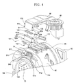
- FIG. 4 is a perspective view, in part, illustrating the washing machine with drying function according to the first preferred embodiment of the present invention, before the connecting duct 100 shown in FIG. 3 is attached to the tub 60 and the heater duct 90.
- connection duct 100 is fixed to the upper position of the front part of the tub 60 by means of fixing bolts 101 and 102.
- left and right fixing bosses 61f and 61g having fixing holes 61d and 61e formed therethrough, respectively.
- the left and right fixing bosses 61f and 61g are protruded forward while being spaced apart from each other right and left.
- At the lower parts of both sides of the connection duct 100 are disposed left and right lower fixing pieces 103 and 104, which are protruded outward, respectively.
- the left and right lower fixing pieces 103 and 104 are provided with fixing holes 103a and 104a corresponding to the fixing holes 61d and 61e of the left and right fixing bosses 61f and 61g, respectively.
- connection duct 100 is connected to the tub 60 as follows: the tub gasket 110 is fitted onto the stepped end 11 of the connection duct 100, and the stepped end 111 of the connection duct 100 is inserted into the second communication hole 64b of the tub 60. As a result, the connection duct 100 is tightly fitted in the tub 60 while the tub gasket 110 is disposed between the connection duct 100 and the tub 60.
- the stepped end 111 of the connection duct 100 is fitted in the second communication hole 64b of the tub 60 such that the stepped end 111 of the connection duct 100 cannot be moved to the front, the rear, the left, and the right.
- the fixing hole 103a of the left lower fixing piece 103 of the connection duct 100 fully communicates with the fixing hole 61d of the left fixing boss 61f
- the fixing hole 104a of the right lower fixing piece 104 of the connection duct 100 fully communicates with the fixing hole 61e of the right fixing boss 61g.
- connection duct 100 is conveniently and quickly connected to the tub 60.
- connection duct 100 is fixed to the heater duct 90 by means of fixing bolts 105 and 106.
- left and right lower fixing pieces 91 and 92 At both sides of the front end of the heater duct 90 are disposed left and right lower fixing pieces 91 and 92, which are protruded outward, respectively.
- the left and right lower fixing pieces 91 and 92 have fixing holes 91a and 91b formed therethrough, respectively.
- left and right upper fixing pieces 107 and 108 At the upper parts of both sides of the upper end of the connection duct 100 are disposed left and right upper fixing pieces 107 and 108, which are protruded outward, respectively.
- the left and right upper fixing pieces 107 and 108 are provided with fixing holes 107a and 108a corresponding to the fixing holes 91a and 92a of the left and right lower fixing pieces 91 and 92 of the heater duct 90, respectively.
- connection duct 100 is connected to the heater duct 90 as follows: the heater duct gasket 120 is disposed between the upper end of the connection duct 100 and the outlet of the heater duct 90. While the fixing hole 107a of the left upper fixing piece 107 of the connection duct 100 fully communicates with the fixing hole 91a of the left lower fixing piece 91 of the heater duct 90, the third fixing bolt 105 is inserted through the fixing hole 91a of the left lower fixing piece 91 and the fixing hole 107a of the left upper fixing piece 107.
- the fourth fixing bolt 106 is inserted through the fixing hole 92a of the right lower fixing piece 92 and the fixing hole 108a of the right upper fixing piece 108.
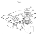
- FIG. 5 is an exploded perspective view illustrating the heater duct 90 shown in FIGS. 2 to 4.
- the heater duct 90 comprises: a duct body 96 attached to the tub 60, the duct body 96 having the open upper part, the duct body 96 having the heater 85 and the blowing fan 87 disposed therein, the duct body 96 being manufactured through die casting of an aluminum material; and an upper cover 98 disposed to cover the open upper part of the duct body 96, the upper cover 98 being provided with a fan motor location part 98a corresponding to the blowing fan 87, the upper cover 98 being manufactured by pressing a stainless material.
- An aluminum material is put in a die-casting mold where the aluminum material is pressed under a predetermined pressure. In this way, the duct body 96 is manufactured.
- a plurality of fixing ribs 96a which are fixed to the fixing bracket 95 shown in FIG. 4 by means of fixing bolts.
- a gasket 97 which extends along the upper edge of the duct body 96 for sealing the space between the upper edge of the duct body 96 and the lower surface of the upper cover 98.
- a fan motor bracket 99 which is disposed on the fan motor location part 98a.
- the fan motor bracket 99 is formed in the shape of an annular ring.
- the fan motor 88 is fixed to the fan motor location part 98a, while being disposed at a prescribed height, by the fan motor bracket 99.
- the upper cover 98 is manufactured by pressing a stainless panel such that the upper cover 98 can be flexibly adapted to the duct body 96 although the shape and the length of the duct body 96 are changed. Consequently, it is not necessary to provide an additional mold for manufacturing the upper cover 98.
- wash water is supplied into the tub 60 by the water-supply unit 62.
- the wash water supplied into the tub 60 is introduced into the drum 70 through the opening hole 71 or the through-holes 72 of the drum 70 such that the laundry in the drum 70 is wetted.
- the drum 70 When the motor 66 is driven while the wash water is supplied as described above, the drum 70 is rotated. As the drum 70 is rotated, the laundry in the drum 70 is shaken by the lifts 73, and therefore, contaminants are removed from the laundry.
- the contaminated wash water in the tub 60 is drained out of the washing machine by the drainage unit 63.
- new wash water is supplied into the tub 60 by the water-supply unit 62.
- the new wash water supplied into the tub 60 is introduced into the drum 70 through the opening hole 71 or the through-holes 72 of the drum 70 such that the laundry in the drum 70 is wetted.
- the drum 70 is rotated. As the drum 70 is rotated, the laundry in the drum 70 is shaken by the lifts 73, and therefore, bubbles left in the laundry are rinsed out.
- the contaminated wash water in the tub 60 is drained out of the washing machine by the drainage unit 63.
- the drum 70 is rotated at high speed as the motor 66 is driven at high speed. As the drum 70 is rotated, the water is centrifugally separated from the laundry while the laundry is pushed against the inner circumferential part of the drum 70. The water centrifugally separated from the laundry is drained out of the washing machine by the drainage unit 63.
- the drum 70 is rotated as the motor 66 is driven. As the drum 70 is rotated, the laundry m is agitated in the drum 70 by the lifts 73.
- the cooling water valve 83 and the heater 85 are turned on, and the fan motor 88 is driven to rotate the blowing fan 87.
- cooling water valve 83 As the cooling water valve 83 is turned on, i.e., opened, cooling water B is injected into the condensing duct 80. Air A in the drum 70, flowing as the blowing fan 87 is rotated, comes into contact with the laundry m. As a result, the temperature of the air is lowered and the humidity of the air is raised.
- the low-temperature and high-humidity air A in the drum 70 passes through the through-holes 72, and is then guided to the outside of the drum 70. Subsequently, the low-temperature and high-humidity air A passes through the first communication hole 64a of the tub 60, and is then guided into the condensing duct 80.
- the low-temperature and high-humidity air A guided into the condensing duct 80 is condensed by the cooling water B injected into the condensing duct 80. As a result, the temperature of the air is lowered and the humidity of the air is also lowered. Subsequently, the low-temperature and low-humidity air is guided into the heater duct 90.
- the air A guided into the heater duct 90 is heated by the heater 85. As a result, the air A is changed into hot wind of high-temperature and low-humidity.
- the hot wind A is guided into the connection duct 100.
- the hot wind A guided into the connection duct 100 passes through the second communication hole 64b of the tub 60, and is then directly guided into the tub 60. Subsequently, the hot wind A is guided into the drum 70 through the hot wind through-holes 74 of the drum 70 or the opening hole 71 of the drum 70. The hot wind A guided into the drum 70 comes into contact with the laundry m, and therefore, takes moisture from the laundry m.
- the air A in the drum 70 is repeatedly circulated/condensed/heated as described above so as to completely dry the laundry m.
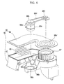
- FIG. 6 is an exploded perspective view illustrating principal components of a washing machine with drying function according to a second preferred embodiment of the present invention.
- the washing machine with drying function further comprises: a motor 88a mounted to the heater duct 90; a driving pulley 88b connected to the motor 88a via a shaft; a driven pulley 88c connected to the blowing fan 87 via a shaft; and a belt 88d wound on the driving pulley 88b and the driven pulley 88c.
- the motor 88a is provided with a motor mounter 88e, which is fixed to the heater duct 90 by means of fixing bolts.
- the heater duct 90 comprises: a duct body 96 attached to the tub 60, the duct body 96 having the open upper part, the duct body 96 having the heater 85 and the blowing fan 87 disposed therein, the duct body 96 being manufactured through die casting of an aluminum material; and an upper cover 98 disposed to cover the open upper part of the duct body 96, the upper cover 98 being provided with a driven pulley location part 98a' corresponding to the blowing fan 87, the upper cover 98 being manufactured by pressing a stainless material.
- fixing ribs 96a which are fixed to the fixing bracket attached to the tub by means of fixing bolts.
- a motor mounting part 96b is also formed at the duct body 96, to which the motor 88a is mounted.
- fixing ribs 96c are formed at the motor mounting part 96b, through which fixing bolts are inserted, respectively, such that the motor mounter 88e is fixed to the motor mounting part 96b.
- the washing machine with drying function according to the second preferred embodiment of the present invention is identical in construction and operation to the washing machine with drying function according to the first preferred embodiment of the present invention except for specific components of the washing machine with drying function, such as the motor 88a, the driving pulley 88b, the driven pulley 88c, the belt 88d, the motor mounting part 96b, and the driven pulley location part 98a'. Therefore, other components of the washing machine with drying function according to the second preferred embodiment of the present invention, which correspond to those of the washing machine with drying function according to the first preferred embodiment of the present invention, are indicated by the same reference numerals as those of the washing machine with drying function according to the first preferred embodiment of the present invention, and a detailed description thereof will not be given.
- the driving pulley 88b and the driven pulley 88c are rotated as the motor 88a is driven, and the blowing fan 87 is rotated along with the driven pulley 88c to circulate air.
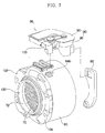
- FIG. 7 is an exploded perspective view illustrating principal components of a washing machine with drying function according to a third preferred embodiment of the present invention.
- the second communication hole 64b is formed at the circumferential part of the tub 60, and the connection duct 100 is fixed to the circumferential part of the tub 60 by means of fixing bolts such that the connection duct 100 communicates with the second communication hole 64b.
- the second communication hole 64b is formed at the upper position of the circumferential part of the tub 60.
- the washing machine with drying function according to the third preferred embodiment of the present invention is identical in construction and operation to the washing machine with drying function according to the first or second preferred embodiment of the present invention except that the second communication hole 64b is formed at the circumferential part of the tub 60, and the connection duct 100 is fixed to the circumferential part of the tub 60. Therefore, other components of the washing machine with drying function according to the third preferred embodiment of the present invention, which correspond to those of the washing machines with drying function according to the first and second preferred embodiments of the present invention, are indicated by the same reference numerals as those of the washing machines with drying function according to the first and second preferred embodiments of the present invention, and a detailed description thereof will not be given.
- the washing machine with drying function according to the present invention has the following effects.
- the washing machine with drying function of the present invention has an effect in that hot wind heated while passing through the drying duct is directly supplied into the tub, whereby flow and heat loss of the hot wind is minimized, and thus, the drying performance of the washing machine with drying function is improved.
- the washing machine with drying function of the present invention has an effect in that the heater duct, which has the heater and the blowing fan mounted therein, communicates with the condensing duct, and the connection duct, which guides air having passed through the heater duct into the tub, communicates with the heater duct and the tub, whereby flow and heat loss of the hot wind is minimized, and thus, the drying performance of the washing machine with drying function is improved.
- the washing machine with drying function of the present invention has an effect in that air having passed through the heater duct is guided along the connection duct, not through the gasket, whereby damage to the gasket, which may be caused when the air having passed the heater duct is guided through the gasket, is prevented, and thus, the service life of the gasket is prevented from being shortened.
- the washing machine with drying function of the present invention has an effect in that the heater duct gasket is disposed between the heater duct and the connection duct, and the tub gasket is disposed between the connection duct and the tub, whereby outflow of hot wind is minimized.
- connection duct is fixed to the upper position of the front part of the tub by means of the fixing bolts, and the connection duct is also fixed to the lower end of the heater duct by means of the fixing bolts, whereby easy and convenient fixing of the connection duct is accomplished.
- the washing machine with drying function of the present invention has an effect in that a plurality of hot wind through-holes are formed at the drum such that hot wind having passed through the connection duct can be directly guided into the drum, whereby the smooth flow of air is accomplished, and thus, the drying performance of the washing machine with drying function is improved.
- the washing machine with drying function of the present invention has an effect in that the heater duct comprises the duct body having the open upper part and manufactured through die casting of an aluminum material, and the upper cover disposed to cover the open upper part of the duct body and manufactured by pressing a stainless material such that the upper cover can be flexibly adapted to the duct body although the shape and the length of the duct body are changed, whereby the manufacturing costs and the weight of the heater duct are reduced, and thus, the productivity of the heater duct is improved.
Landscapes
- Engineering & Computer Science (AREA)
- Textile Engineering (AREA)
- Detail Structures Of Washing Machines And Dryers (AREA)
- Main Body Construction Of Washing Machines And Laundry Dryers (AREA)
- Drying Of Solid Materials (AREA)
Abstract
Description
Claims (17)
- A washing machine with drying function, comprising:a tub (60) disposed in a cabinet (50) while being supported;a drum (70) rotatably disposed inside the tub (60), the drum (70) being provided with through-holes (72);a condensing duct (80) communicating with one side of the tub (60); anda drying duct (86) communicating with the condensing duct (80), the drying duct (86) having a heater (85) and a blowing fan (87) mounted therein, the drying duct (86) communicating with the other side of the tub (60).
- The washing machine as set forth in claim 1, wherein the tub (60) is provided at one side thereof with a first communication hole (64a) communicating with the condensing duct (80), and at the other side thereof with a second communication hole (64b) communicating with the drying duct (86).
- The washing machine as set forth in claim 2, wherein the first communication hole (64a) is formed at a rear part of the tub (60).
- The washing machine as set forth in claim 2, wherein the second communication hole (64b) is formed at a front part of the tub (60).
- The washing machine as set forth in claim 4, wherein the second communication hole (64b) is formed at an upper position of the front part of the tub (60).
- The washing machine as set forth in claim 2, wherein the second communication hole (64b) is formed at a circumferential part of the tub (60).
- The washing machine as set forth in any one of claims 1 to 6, wherein the drying duct (86) comprises:a heater duct (90) having one end communicating with the condensing duct (80), the heater duct (90) having the heater (85) and the blowing fan (87) mounted therein; anda connection duct (100) having one end communicating with the heater duct (90) and the other end communicating with the second communication hole (64b) of the tub (60).
- The washing machine as set forth in claim 7, further comprising:a heater duct gasket (120) disposed between the heater duct (90) and the connection duct (100) for sealing a space between the heater duct (90) and the connection duct (100).
- The washing machine as set forth in claim 7, further comprising:a tub gasket (110) disposed between the connection duct (100) and the tub (60) for sealing a space between the connection duct (100) and the tub (60).
- The washing machine as set forth in claim 7, further comprising:a heater duct gasket (120) disposed between the heater duct (90) and the connection duct (100) for sealing a space between the heater duct (90) and the connection duct (100); anda tub gasket (110) disposed between the connection duct (100) and the tub (60) for sealing a space between the connection duct (100) and the tub (60).
- The washing machine as set forth in claim 7, further comprising:a fan motor (88), to which the blowing fan (87) is connected via a shaft,
wherein the heater duct (90) comprises:a duct body (96) attached to the tub (60), the duct body (96) having an open upper part, the duct body (96) having the heater (85) and the blowing fan (87) disposed therein, the duct body (96) being manufactured through die casting of an aluminum material; andan upper cover (98) disposed to cover the open upper part of the duct body (96), the upper cover (98) being provided with a fan motor location part (98a) corresponding to the blowing fan (87), the upper cover (98) being manufactured by pressing a stainless material. - The washing machine as set forth in claim 7, further comprising:a motor (88a) mounted to the heater duct (90);a driving pulley (88b) connected to the motor (88a) via a shaft;a driven pulley (88c) connected to the blowing fan (87) via a shaft; anda belt (88d) wound on the driving pulley (88b) and the driven pulley (88c),
wherein the heater duct (90) comprises:a duct body (96) attached to the tub (60), the duct body (96) having an open upper part, the duct body (96) having the heater (85) and the blowing fan (87) disposed therein, the duct body (96) being manufactured through die casting of an aluminum material; andan upper cover (98) disposed to cover the open upper part of the duct body (96), the upper cover (98) being provided with a driven pulley location part (98a') corresponding to the blowing fan (87), the upper cover (98) being manufactured by pressing a stainless material. - The washing machine as set forth in claim 7, wherein the connection duct (100) is fixed to the tub (60) by means of fixing bolts (101, 102).
- The washing machine as set forth in claim 13, wherein
the tub is provided with bosses (61f, 61g), and
the connection duct (100) is fixed to the bosses (61f, 61g) by means of the fixing bolts (101, 102). - The washing machine as set forth in claim 7, wherein the connection duct (100) is provided with a stepped end (111), the stepped end (111) being inserted in the second communication hole (64b) of the tub (60).
- The washing machine as set forth in claim 7, wherein the connection duct (100) is fixed to the heater duct (90) by means of fixing bolts (105, 106).
- The washing machine as set forth in any one of claims 1 to 16, wherein the drum (70) is provided at a front part thereof with a plurality of hot wind through-holes (74) for introducing hot wind having passed through the second communication hole (64b) of the tub (60) into the drum (70).
Applications Claiming Priority (6)
| Application Number | Priority Date | Filing Date | Title |
|---|---|---|---|
| KR1020030093191A KR100546612B1 (en) | 2003-12-18 | 2003-12-18 | Drum washing machine |
| KR2003093191 | 2003-12-18 | ||
| KR1020040011463A KR100565658B1 (en) | 2004-02-20 | 2004-02-20 | Drying duct of drum washing machine |
| KR2004011463 | 2004-02-20 | ||
| KR1020040089899A KR100733298B1 (en) | 2004-11-05 | 2004-11-05 | Drying Washer |
| KR2004089899 | 2004-11-05 |
Publications (3)
| Publication Number | Publication Date |
|---|---|
| EP1544341A2 true EP1544341A2 (en) | 2005-06-22 |
| EP1544341A3 EP1544341A3 (en) | 2007-05-16 |
| EP1544341B1 EP1544341B1 (en) | 2014-09-17 |
Family
ID=34527624
Family Applications (1)
| Application Number | Title | Priority Date | Filing Date |
|---|---|---|---|
| EP04029989.3A Expired - Lifetime EP1544341B1 (en) | 2003-12-18 | 2004-12-17 | Washing machine with drying function |
Country Status (4)
| Country | Link |
|---|---|
| US (1) | US20050138973A1 (en) |
| EP (1) | EP1544341B1 (en) |
| JP (1) | JP4490251B2 (en) |
| CN (1) | CN100535229C (en) |
Cited By (1)
| Publication number | Priority date | Publication date | Assignee | Title |
|---|---|---|---|---|
| CN109680451A (en) * | 2019-01-09 | 2019-04-26 | Tcl家用电器(合肥)有限公司 | Washing machine drying channel structure and washing machine |
Families Citing this family (14)
| Publication number | Priority date | Publication date | Assignee | Title |
|---|---|---|---|---|
| US20050229647A1 (en) * | 2004-04-20 | 2005-10-20 | Lg Electronics Inc. | Dryer washer |
| DE102006029709A1 (en) * | 2005-06-30 | 2007-03-22 | Lg Electronics Inc. | Housing a laundry handling device |
| KR101202748B1 (en) * | 2005-07-15 | 2012-11-19 | 주식회사 대우일렉트로닉스 | Apparatus for removing foam of drum-type washing machine |
| KR101196984B1 (en) * | 2005-08-19 | 2012-11-05 | 엘지전자 주식회사 | A drum type washing machine and drying duct assembly combined therein |
| KR101071842B1 (en) * | 2009-03-03 | 2011-10-11 | 엘지전자 주식회사 | A washing machine |
| EP2423370B1 (en) * | 2010-08-24 | 2013-04-17 | Electrolux Home Products Corporation N.V. | Rotary-drum laundry dryer |
| CN102277708B (en) * | 2011-07-01 | 2016-05-18 | 佛山海尔滚筒洗衣机有限公司 | A kind of inner/outer drum structure with drying function washing machine |
| CN103726264B (en) * | 2012-10-12 | 2017-02-01 | 苏州三星电子有限公司 | Clothes washing and drying machine |
| CN104018318A (en) * | 2013-02-28 | 2014-09-03 | 海尔集团技术研发中心 | Dry cleaning machine |
| EP3162949B1 (en) * | 2015-10-30 | 2018-05-02 | Whirlpool EMEA S.p.A | Support element adapted to connect a drying system of a household appliance configured to perform at least a drying cycle, and household appliance comprising such a support element |
| KR20180023277A (en) | 2016-08-25 | 2018-03-07 | 엘지전자 주식회사 | Laundry Apparatus |
| KR20180136786A (en) * | 2017-06-15 | 2018-12-26 | 주식회사 대우전자 | Wall mounted drum type washing machine |
| KR102377042B1 (en) * | 2017-08-09 | 2022-03-22 | 엘지전자 주식회사 | clothes processing equipment |
| CN111719297B (en) * | 2019-03-19 | 2022-02-25 | 无锡小天鹅电器有限公司 | Clothes treating apparatus |
Citations (11)
| Publication number | Priority date | Publication date | Assignee | Title |
|---|---|---|---|---|
| EP0073898A1 (en) | 1981-09-03 | 1983-03-16 | INDUSTRIE ZANUSSI S.p.A. | Combined machine for washing and drying laundry |
| EP0252323A2 (en) | 1986-07-11 | 1988-01-13 | INDUSTRIE ZANUSSI S.p.A. | Combined laundry washing and drying machine |
| EP0380992A1 (en) | 1989-01-25 | 1990-08-08 | MERLONI ELETTRODOMESTICI S.p.A. | Improved clothes washing and drying appliance |
| JPH04170996A (en) | 1990-11-02 | 1992-06-18 | Matsushita Electric Ind Co Ltd | Drum type washing drier |
| JPH04240482A (en) | 1991-01-24 | 1992-08-27 | Matsushita Electric Ind Co Ltd | Drum type washing and drying machine |
| EP1094141A2 (en) | 1999-10-21 | 2001-04-25 | Kabushiki Kaisha Toshiba | Drum type washing machine with drying function |
| EP1152082A2 (en) | 2000-04-27 | 2001-11-07 | Electrolux Zanussi S.p.A. | Top-loading clothes washing and drying machine with substantially horizontal-axis rotating drum |
| JP2003164691A (en) | 2001-11-29 | 2003-06-10 | Sanyo Electric Co Ltd | Drum type washing machine |
| JP2003245489A (en) | 2002-02-26 | 2003-09-02 | Toshiba Corp | Washing and drying machine |
| JP2003290588A (en) | 2002-04-01 | 2003-10-14 | Toshiba Corp | Washing and drying machine |
| EP1353004A1 (en) | 2002-04-09 | 2003-10-15 | Bonferraro S.p.A. | Washing machine with self-cleaning drying circuit |
Family Cites Families (6)
| Publication number | Priority date | Publication date | Assignee | Title |
|---|---|---|---|---|
| US3186104A (en) * | 1955-05-26 | 1965-06-01 | Hupp Corp | Clothes drier with variable speed centrifuge and heat supply |
| US2875526A (en) * | 1955-12-01 | 1959-03-03 | Murray Corp | Combined washer and drier |
| US3902337A (en) * | 1973-10-15 | 1975-09-02 | Mc Graw Edison Co | Laundry system with drying tumbler |
| JPS5861797A (en) * | 1981-10-09 | 1983-04-12 | 株式会社東芝 | Dryer |
| US5121615A (en) * | 1991-06-05 | 1992-06-16 | Taiwan Electric Heating Equipment Co., Ltd. | Drying device incorporated with a washing machine |
| US20040221624A1 (en) * | 2002-06-20 | 2004-11-11 | Silvano Fumagalli | Washington machine for household use with two compartments |
-
2004
- 2004-12-16 US US11/012,094 patent/US20050138973A1/en not_active Abandoned
- 2004-12-17 EP EP04029989.3A patent/EP1544341B1/en not_active Expired - Lifetime
- 2004-12-20 CN CNB2004101019020A patent/CN100535229C/en not_active Expired - Fee Related
- 2004-12-20 JP JP2004367797A patent/JP4490251B2/en not_active Expired - Fee Related
Patent Citations (11)
| Publication number | Priority date | Publication date | Assignee | Title |
|---|---|---|---|---|
| EP0073898A1 (en) | 1981-09-03 | 1983-03-16 | INDUSTRIE ZANUSSI S.p.A. | Combined machine for washing and drying laundry |
| EP0252323A2 (en) | 1986-07-11 | 1988-01-13 | INDUSTRIE ZANUSSI S.p.A. | Combined laundry washing and drying machine |
| EP0380992A1 (en) | 1989-01-25 | 1990-08-08 | MERLONI ELETTRODOMESTICI S.p.A. | Improved clothes washing and drying appliance |
| JPH04170996A (en) | 1990-11-02 | 1992-06-18 | Matsushita Electric Ind Co Ltd | Drum type washing drier |
| JPH04240482A (en) | 1991-01-24 | 1992-08-27 | Matsushita Electric Ind Co Ltd | Drum type washing and drying machine |
| EP1094141A2 (en) | 1999-10-21 | 2001-04-25 | Kabushiki Kaisha Toshiba | Drum type washing machine with drying function |
| EP1152082A2 (en) | 2000-04-27 | 2001-11-07 | Electrolux Zanussi S.p.A. | Top-loading clothes washing and drying machine with substantially horizontal-axis rotating drum |
| JP2003164691A (en) | 2001-11-29 | 2003-06-10 | Sanyo Electric Co Ltd | Drum type washing machine |
| JP2003245489A (en) | 2002-02-26 | 2003-09-02 | Toshiba Corp | Washing and drying machine |
| JP2003290588A (en) | 2002-04-01 | 2003-10-14 | Toshiba Corp | Washing and drying machine |
| EP1353004A1 (en) | 2002-04-09 | 2003-10-15 | Bonferraro S.p.A. | Washing machine with self-cleaning drying circuit |
Cited By (1)
| Publication number | Priority date | Publication date | Assignee | Title |
|---|---|---|---|---|
| CN109680451A (en) * | 2019-01-09 | 2019-04-26 | Tcl家用电器(合肥)有限公司 | Washing machine drying channel structure and washing machine |
Also Published As
| Publication number | Publication date |
|---|---|
| EP1544341B1 (en) | 2014-09-17 |
| CN100535229C (en) | 2009-09-02 |
| US20050138973A1 (en) | 2005-06-30 |
| JP2005177505A (en) | 2005-07-07 |
| JP4490251B2 (en) | 2010-06-23 |
| EP1544341A3 (en) | 2007-05-16 |
| CN1629387A (en) | 2005-06-22 |
Similar Documents
| Publication | Publication Date | Title |
|---|---|---|
| US7421865B2 (en) | Washing machine with drying function and method of controlling the same | |
| EP3159449B1 (en) | Drum type washing and drying machine | |
| EP1544341A2 (en) | Washing machine with drying function | |
| KR102656144B1 (en) | Washing machine | |
| US7228647B2 (en) | Drying machine and drying machine with washing function and method of controlling the same | |
| KR102648423B1 (en) | Stacking Type cloth treating apparatus | |
| EP1584729B1 (en) | Washing-drying machine | |
| KR100550690B1 (en) | washer | |
| US20060021250A1 (en) | Apparatus for supplying hot air in drum type washer with dry function | |
| JPH11114273A (en) | Drum type washer / dryer | |
| US20060059959A1 (en) | Washing machine | |
| KR100733298B1 (en) | Drying Washer | |
| KR20030084066A (en) | Drum type washing and drying apparatus | |
| KR100657474B1 (en) | Washing machine with dryer | |
| KR100416491B1 (en) | Combination washer-drier | |
| JP2000084286A (en) | Drum type washer / dryer | |
| KR0127663Y1 (en) | Washer combined with dry function | |
| JP7106506B2 (en) | washing machine | |
| KR101629293B1 (en) | Method for controlling drying in washing machine | |
| JP3113272B2 (en) | Washing machine | |
| KR100624728B1 (en) | Drying Washer | |
| KR20250110070A (en) | Clothes treating apparatus | |
| KR101263864B1 (en) | Fan motor of drying and washing machine | |
| JP2022180071A (en) | washing machine | |
| JP2022159584A (en) | washing machine |
Legal Events
| Date | Code | Title | Description |
|---|---|---|---|
| PUAI | Public reference made under article 153(3) epc to a published international application that has entered the european phase |
Free format text: ORIGINAL CODE: 0009012 |
|
| 17P | Request for examination filed |
Effective date: 20041217 |
|
| AK | Designated contracting states |
Kind code of ref document: A2 Designated state(s): AT BE BG CH CY CZ DE DK EE ES FI FR GB GR HU IE IS IT LI LT LU MC NL PL PT RO SE SI SK TR |
|
| AX | Request for extension of the european patent |
Extension state: AL BA HR LV MK YU |
|
| PUAL | Search report despatched |
Free format text: ORIGINAL CODE: 0009013 |
|
| AK | Designated contracting states |
Kind code of ref document: A3 Designated state(s): AT BE BG CH CY CZ DE DK EE ES FI FR GB GR HU IE IS IT LI LT LU MC NL PL PT RO SE SI SK TR |
|
| AX | Request for extension of the european patent |
Extension state: AL BA HR LV MK YU |
|
| AKX | Designation fees paid |
Designated state(s): DE FR GB |
|
| 17Q | First examination report despatched |
Effective date: 20111118 |
|
| GRAP | Despatch of communication of intention to grant a patent |
Free format text: ORIGINAL CODE: EPIDOSNIGR1 |
|
| INTG | Intention to grant announced |
Effective date: 20140411 |
|
| RAP1 | Party data changed (applicant data changed or rights of an application transferred) |
Owner name: LG ELECTRONICS INC. |
|
| GRAS | Grant fee paid |
Free format text: ORIGINAL CODE: EPIDOSNIGR3 |
|
| GRAA | (expected) grant |
Free format text: ORIGINAL CODE: 0009210 |
|
| AK | Designated contracting states |
Kind code of ref document: B1 Designated state(s): DE FR GB |
|
| REG | Reference to a national code |
Ref country code: GB Ref legal event code: FG4D |
|
| REG | Reference to a national code |
Ref country code: DE Ref legal event code: R096 Ref document number: 602004045836 Country of ref document: DE Effective date: 20141023 |
|
| REG | Reference to a national code |
Ref country code: DE Ref legal event code: R097 Ref document number: 602004045836 Country of ref document: DE |
|
| PLBE | No opposition filed within time limit |
Free format text: ORIGINAL CODE: 0009261 |
|
| STAA | Information on the status of an ep patent application or granted ep patent |
Free format text: STATUS: NO OPPOSITION FILED WITHIN TIME LIMIT |
|
| 26N | No opposition filed |
Effective date: 20150618 |
|
| REG | Reference to a national code |
Ref country code: FR Ref legal event code: PLFP Year of fee payment: 12 |
|
| REG | Reference to a national code |
Ref country code: FR Ref legal event code: PLFP Year of fee payment: 13 |
|
| REG | Reference to a national code |
Ref country code: FR Ref legal event code: PLFP Year of fee payment: 14 |
|
| PGFP | Annual fee paid to national office [announced via postgrant information from national office to epo] |
Ref country code: GB Payment date: 20171107 Year of fee payment: 14 |
|
| REG | Reference to a national code |
Ref country code: FR Ref legal event code: PLFP Year of fee payment: 15 |
|
| GBPC | Gb: european patent ceased through non-payment of renewal fee |
Effective date: 20181217 |
|
| PG25 | Lapsed in a contracting state [announced via postgrant information from national office to epo] |
Ref country code: GB Free format text: LAPSE BECAUSE OF NON-PAYMENT OF DUE FEES Effective date: 20181217 |
|
| PGFP | Annual fee paid to national office [announced via postgrant information from national office to epo] |
Ref country code: DE Payment date: 20191105 Year of fee payment: 16 |
|
| PGFP | Annual fee paid to national office [announced via postgrant information from national office to epo] |
Ref country code: FR Payment date: 20191107 Year of fee payment: 16 |
|
| REG | Reference to a national code |
Ref country code: DE Ref legal event code: R119 Ref document number: 602004045836 Country of ref document: DE |
|
| PG25 | Lapsed in a contracting state [announced via postgrant information from national office to epo] |
Ref country code: FR Free format text: LAPSE BECAUSE OF NON-PAYMENT OF DUE FEES Effective date: 20201231 |
|
| PG25 | Lapsed in a contracting state [announced via postgrant information from national office to epo] |
Ref country code: DE Free format text: LAPSE BECAUSE OF NON-PAYMENT OF DUE FEES Effective date: 20210701 |