EP1544022A2 - Operation assistance system and method - Google Patents
Operation assistance system and method Download PDFInfo
- Publication number
- EP1544022A2 EP1544022A2 EP04029611A EP04029611A EP1544022A2 EP 1544022 A2 EP1544022 A2 EP 1544022A2 EP 04029611 A EP04029611 A EP 04029611A EP 04029611 A EP04029611 A EP 04029611A EP 1544022 A2 EP1544022 A2 EP 1544022A2
- Authority
- EP
- European Patent Office
- Prior art keywords
- intention
- time
- operator
- estimated
- imaginary
- Prior art date
- Legal status (The legal status is an assumption and is not a legal conclusion. Google has not performed a legal analysis and makes no representation as to the accuracy of the status listed.)
- Granted
Links
- 238000000034 method Methods 0.000 title claims abstract description 25
- 238000006243 chemical reaction Methods 0.000 claims description 104
- 230000000717 retained effect Effects 0.000 claims description 15
- 230000001133 acceleration Effects 0.000 claims description 5
- 238000004364 calculation method Methods 0.000 claims description 4
- 230000008859 change Effects 0.000 description 21
- 230000006870 function Effects 0.000 description 14
- 230000004044 response Effects 0.000 description 13
- 230000004048 modification Effects 0.000 description 8
- 238000012986 modification Methods 0.000 description 8
- 230000006399 behavior Effects 0.000 description 6
- 238000013500 data storage Methods 0.000 description 4
- 230000007423 decrease Effects 0.000 description 4
- 238000010586 diagram Methods 0.000 description 4
- 230000009467 reduction Effects 0.000 description 4
- 230000008901 benefit Effects 0.000 description 3
- 210000005252 bulbus oculi Anatomy 0.000 description 3
- 230000003247 decreasing effect Effects 0.000 description 3
- 230000000694 effects Effects 0.000 description 3
- 230000008569 process Effects 0.000 description 3
- 230000004075 alteration Effects 0.000 description 2
- 230000007246 mechanism Effects 0.000 description 2
- 230000009471 action Effects 0.000 description 1
- 230000005540 biological transmission Effects 0.000 description 1
- 230000001419 dependent effect Effects 0.000 description 1
- 238000003384 imaging method Methods 0.000 description 1
- 230000005855 radiation Effects 0.000 description 1
- 230000001105 regulatory effect Effects 0.000 description 1
Images


Classifications
-
- B—PERFORMING OPERATIONS; TRANSPORTING
- B60—VEHICLES IN GENERAL
- B60W—CONJOINT CONTROL OF VEHICLE SUB-UNITS OF DIFFERENT TYPE OR DIFFERENT FUNCTION; CONTROL SYSTEMS SPECIALLY ADAPTED FOR HYBRID VEHICLES; ROAD VEHICLE DRIVE CONTROL SYSTEMS FOR PURPOSES NOT RELATED TO THE CONTROL OF A PARTICULAR SUB-UNIT
- B60W50/00—Details of control systems for road vehicle drive control not related to the control of a particular sub-unit, e.g. process diagnostic or vehicle driver interfaces
- B60W50/08—Interaction between the driver and the control system
- B60W50/14—Means for informing the driver, warning the driver or prompting a driver intervention
- B60W50/16—Tactile feedback to the driver, e.g. vibration or force feedback to the driver on the steering wheel or the accelerator pedal
-
- B—PERFORMING OPERATIONS; TRANSPORTING
- B60—VEHICLES IN GENERAL
- B60W—CONJOINT CONTROL OF VEHICLE SUB-UNITS OF DIFFERENT TYPE OR DIFFERENT FUNCTION; CONTROL SYSTEMS SPECIALLY ADAPTED FOR HYBRID VEHICLES; ROAD VEHICLE DRIVE CONTROL SYSTEMS FOR PURPOSES NOT RELATED TO THE CONTROL OF A PARTICULAR SUB-UNIT
- B60W40/00—Estimation or calculation of non-directly measurable driving parameters for road vehicle drive control systems not related to the control of a particular sub unit, e.g. by using mathematical models
- B60W40/08—Estimation or calculation of non-directly measurable driving parameters for road vehicle drive control systems not related to the control of a particular sub unit, e.g. by using mathematical models related to drivers or passengers
- B60W40/09—Driving style or behaviour
-
- B—PERFORMING OPERATIONS; TRANSPORTING
- B60—VEHICLES IN GENERAL
- B60W—CONJOINT CONTROL OF VEHICLE SUB-UNITS OF DIFFERENT TYPE OR DIFFERENT FUNCTION; CONTROL SYSTEMS SPECIALLY ADAPTED FOR HYBRID VEHICLES; ROAD VEHICLE DRIVE CONTROL SYSTEMS FOR PURPOSES NOT RELATED TO THE CONTROL OF A PARTICULAR SUB-UNIT
- B60W50/00—Details of control systems for road vehicle drive control not related to the control of a particular sub-unit, e.g. process diagnostic or vehicle driver interfaces
- B60W50/0097—Predicting future conditions
-
- B—PERFORMING OPERATIONS; TRANSPORTING
- B60—VEHICLES IN GENERAL
- B60W—CONJOINT CONTROL OF VEHICLE SUB-UNITS OF DIFFERENT TYPE OR DIFFERENT FUNCTION; CONTROL SYSTEMS SPECIALLY ADAPTED FOR HYBRID VEHICLES; ROAD VEHICLE DRIVE CONTROL SYSTEMS FOR PURPOSES NOT RELATED TO THE CONTROL OF A PARTICULAR SUB-UNIT
- B60W50/00—Details of control systems for road vehicle drive control not related to the control of a particular sub-unit, e.g. process diagnostic or vehicle driver interfaces
- B60W50/08—Interaction between the driver and the control system
- B60W50/10—Interpretation of driver requests or demands
Definitions
- the present disclosure relates to system and method for providing assistance based on an operator's intention, and more particularly, to driving assistance system and method for determining a state of an estimated intention of an operator and providing operation assistance accordingly.
- a number of methods and systems have been proposed for providing assistance in operating a device, system or machine, such as a vehicle.
- driving assistance systems were disclosed in U.S. Published Patent Application Nos. 20030060936 A1, published Mar. 27, 2003, and 20040172185 A1, published Sep. 2, 2004.
- some driving assistance systems may require estimation of a driver's intention in driving a vehicle.
- a system for estimating a driver's intention may collect estimates of the driver's intention using movement of the driver's eyeballs. For example, directions to which the driver's eyeballs turn are projected onto a plane divided into a number of regions, for calculating a distribution of projected directions over the divided regions to estimate the driver's intention.
- such type of systems lacks accuracy because the driver's eyeballs move all the time and do not always relate to a "driving" intention of the driver.
- This disclosure presents system, control process and method that provide effective estimation of an operator's intention in operating a device, system or machine, and indicate a state of the estimation of the operator's intentions, which may indicate the strength of the estimated intention. Operation assistance may be provided based on the state of the estimated intention of the operator.
- An exemplary system and method detect an operation performed by an operator of a machine, and generate data related to an estimated intention of the operator based on the detected operation.
- a state of the estimated intention of the operator is then determined.
- the state may indicate the reliability or strength of the estimated intention. For instance, the state may represent a period of time that the operator has retained the estimated intention. The longer the operator retains the intention, the more determined the operator is to perform an action or operation according to the estimated intention.
- an estimated intention of the operator at a specific point in time, and at least one past estimated intention of the operator before the specific point in time are determined.
- An estimated period of time that the operator retains an estimated intention is determined based on the estimated intention of the operator at the specific point in time and the at least one past estimated intention of the operator before the specific point in time.
- the machine is a vehicle and the operator is a driver of the vehicle.
- the estimated intention of the operator is determined by comparing an operation of the operator with reference data, such as data related to a plurality of imaginary operators.
- Each of the plurality of imaginary operators is associated with a sequence of intentions corresponding to different points in time, wherein each of the sequence of intentions is associated with an operation.
- a likelihood value is calculated based on partial likelihood values of each imaginary operator corresponding to the different points in time, wherein each of the partial likelihood values is respectively associated with each respective intention and the respective operation at each one of the different points in time, and is generated based on the respective detected operation of the real operator at each one of the different points in time and the respective operation of the respective one of the plurality of imaginary operators at each one of the different points in time.
- One of the plurality of imaginary operators is selected to approximate to the real operator based on the likelihood value of each one of the imaginary operators.
- a chosen intention of the selected imaginary operator is used to approximate the intention of the real operator.
- the point in time corresponding to the chosen intention and the most recent point in time that the selected imaginary operator retaining an intention different from the chosen intention are determined.
- the period between the two points in time is used to indicate the state of the estimated intention. The longer this period of time is, the stronger the estimated intention is.
- the operation of the machine is adjusted based on the state of the estimated intention.
- a risk potential associated with the vehicle and the driver's intention are constantly monitored and determined.
- a reaction force to be applied or being applied to a vehicle control device is determined based on the calculated risk potential, the estimated intention and the state of the estimated intention.
- the vehicle control device may be any device that a driver manipulates to control the operation of the vehicle, such as an acceleration pedal or a steering wheel, or any device that can provide a haptic feedback to the operator.
- the risk potential is modified based on the state of the estimated intention, and the reaction force is calculated based on the modified risk potential and the estimated intention.
- the reaction force is calculated based on the calculated risk potential and the estimated intention, and is then modified based on the state of the estimated intention.
- an exemplary system 1 includes a vehicle's environment detector 10, a vehicle's status detector 20, a real driver's operation detector 30, an imaginary driver's intention generating section 40, an imaginary driver's operation calculator 50, a likelihood P(j)ids calculator 60, a driver's intention estimator 70, and a section 80 to determine a state of an estimated driver's intention, for instance, by determining how long the estimated driver's intention has been retained.
- the vehicle's environment detector 10 detects a state of environment within a field around the vehicle.
- the vehicle's status detector 20 detects an operation status of the vehicle.
- the real driver's operation detector 30 detects an operation amount of a real driver in driving the vehicle.
- the driver's intention estimating system 1 has access to reference data, such as data related to a plurality of imaginary drivers.
- Each of the imaginary drivers is designed to perform an operation of the vehicle according to an associated intention.
- Examples of the intention may include a lane-keeping intention (LK), a lane-change intention to the right (LCR), and a lane-change intention to the left (LCL).
- LK lane-keeping intention
- LCR lane-change intention to the right
- LCL lane-change intention to the left
- the imaginary driver's intention generating section 40 continuously generates a lane-keeping intention (LK) at every point in time to form a series of intention for a parent imaginary driver. Furthermore, the imaginary driver's intention generating section 40 generates data related to at least one additional imaginary driver based on the intention of the parent imaginary driver. In one embodiment, the imaginary driver's intention generating section 40 generates data related to two additional imaginary drivers, each has one of two derivative lane-change intentions (LCR) and (LCL) based on a lane-keeping intention (LK) of the parent imaginary driver at an immediately preceding pint in time. In another embodiment, the imaginary driver's intention generating section 80 applies special rules in generating series of intentions for the additional imaginary drivers.
- the imaginary driver's intention generating section 40 allows a parent imaginary driver to retain a lane-keeping intention (LK) at every point in time. Further, at every point in time with the parent imaginary driver having a lane-keeping intention (LK), the imaginary driver's intention generating section 40 generates data related to two additional imaginary drivers having lane-change intentions to the right (LCR) and to the left (LCL), respectively, for the next point in time.
- an additional imaginary driver generated at a specific point of time assumes at least some of the intentions for all points of time preceding the specific point in time, from the parent imaginary driver.
- the imaginary driver's intention generating section 40 determines whether or not an imaginary driver retaining one of the derivative lane-change intentions to exist at the next point in time should be allowed to continue to exist, by applying one or more rules.
- an exemplary rule allows the parent imaginary user to retain a lane-keeping intention (LK) at every point in time, and generates data related to two additional imaginary drivers having lane-change intentions (LCR) and (LCL), respectively, at the next point in time.
- LCR lane-keeping intention
- LCL lane-change intentions
- an imaginary driver is allowed to retain a lane-change intention to the right (LCR) at the next point in time if it is determined that the real driver continues to retain a lane-changing intention at the present point in time.
- an imaginary driver is not allowed to retain a lane-change intention to the right (LCR) at the next point in time .
- This is equally applicable to a lane-change intention to the left (LCL).
- an imaginary driver having a lane-change intention to the left (LCL) at a specific point in time is allowed to retain a lane-change intention to the left (LCL) at the next point in time upon determination that a lane change continues, but the imaginary driver is not allowed to continue to retain a lane-change intention to the left (LCL) at a specific point in time upon failure to determine that the lane change continues. Therefore, an imaginary driver that has one of the derivative lane-change intentions (LCR) and (LCL), is allowed to retain the derivative lane-change intention at the next point in time upon determination that a lane change continues.
- each of the imaginary drivers has an associated operation corresponding to an intention retained by that imaginary driver.
- the process for determining an operation associated with each intention is described below.
- the vehicle's environment detector 10 provides information on a state of environment around the vehicle to the imaginary driver's operation calculator 50. Examples of such information include a lateral distance y of the vehicle from a centerline within a lane, and a yaw angle ⁇ of the vehicle with respect a line parallel to the centerline.
- the vehicle's status detector 20 provides information on a status of the vehicle to the imaginary driver's operation calculator 50. Examples of such information include a vehicle speed of the vehicle and a steering angle of the vehicle.
- the imaginary driver's operation calculator 50 calculates operation amounts Oid of the imaginary drivers in a manner that will be described in detail in connection with Fig. 3.
- certain rules are applied to determine whether an existing additional imaginary driver retaining one of the derivative lane-change intentions should be allowed to exist at the next point.. In other words, if a predetermined condition established by the rules is not met by an additional imaginary driver at a specific point in time, that additional imaginary driver is terminated or eliminated. Since it is not necessary to calculate operation amounts Oid of the eliminated imaginary drivers, the computation load is reduced.
- the imaginary driver's operation calculator 50 provides the calculated operation amounts Oid of the imaginary drivers to the likelihood value P(j)ids calculator 60.
- the real driver's operation detector 30 For comparison with each of the calculated operation amounts Oid of the imaginary drivers, the real driver's operation detector 30 provides a detected operation amount Ord to the likelihood value P(j)ids calculator 60.
- An example of the operation amount to be detected is a steering angle of the vehicle.
- the likelihood value P(j)ids calculator 60 calculates a likelihood value Pid(j)(t) of an imaginary driver, based on the associated operation amounts Oid and the detected operation amount Ord.
- the calculated likelihood values Pid(j)(t) are stored in data storage devices, such as memory or hard disk. For each imaginary driver, the data storage device stores the most recent likelihood value Pid(j)(t) after shifting the previously calculated likelihood value.
- the stored likelihood values may be represented in the form of Pid(j)(t), Pid(j)(t-1), ..., Pid(j)(t-m+1), which correspond to likelihood values calculated at different points in time ranging from the present point in time (t) back to (t-m+1).
- the m (a natural number) points in time are arranged at regular intervals and define a predetermined period of time.
- the likelihood value P(j)ids calculator 60 calculates a collective likelihood value P(j)ids for each imaginary driver j based on likelihood values Pid(j)(t), Pid(j)(t-1), ..., Pid(j)(t-m+1)and provides the calculated series-likelihood values P(j)ids for processing at the driver's intention estimator 70.
- the driver's intention estimator 70 selects one of the imaginary drivers to approximate behaviors of the real driver based on the calculated collective likelihood values P(j)ids.
- An intention of the selected imaginary driver such as the most recent intention retained by the selected imaginary driver, is set as an estimated driver's intention ⁇ rd of the real driver.
- section 80 In order to determine a state of an estimated driver's intention ⁇ rd, section 80 is provided. Detailed operation of section 80 will be described later.
- the vehicle's environment detector 10 includes a front camera that covers a field of front view and a yaw angle sensor.
- the front camera acquires images of road conditions, within the field of front view.
- the vehicle's environment detector 10 detects a lateral distance y of the vehicle from a centerline within a lane, and a yaw angle ⁇ of the vehicle with respect a line parallel to the centerline.
- the vehicle's environment detector 10 is equipped with an image processor that processes the acquired image.
- the vehicle's status detector 20 includes a vehicle speed sensor for detecting a speed of the vehicle.
- the real driver's operation detector 30 includes a sensor to detect an operation performed by the driver. Detector 30 may be a steering angle sensor that detects a steering angle of the vehicle. Other types of sensors can be used, such as acceleration sensor or brake sensor.
- the exemplary system 10 includes imaginary driver's intention generating section 40, imaginary driver's operation calculator 50, likelihood value P(j)ids calculator 60, driver's intention estimator 70, and section 80.
- Some or all of these elements are implemented using one or more microcomputers or microcontrollers, such as a central processor unit (CPU), executing microcode, software programs and/or instructions.
- the microcode and/or software reside in volatile and/or non-volatile data storage devices and/or machine-readable data storage medium such as read only memory (ROM) devices, random access memory (RAM) devices, SRAM, PROM, EPROM, CD-ROM, disks, carrier waves, etc.
- the imaginary driver's intention generating section 40 continuously generates data related to imaginary drivers.
- Each of the imaginary drivers retains a series of intentions over a period of time.
- the number of the imaginary drivers and types of intentions retained by the imaginary drivers are dynamic, and may change over time.
- the imaginary driver's operation calculator 50 calculates operation amounts Oid of the imaginary drivers associated with different intentions that are determined by the imaginary driver's intention generating section 40.
- the microcomputer reads in data related to a lateral position y of the vehicle within a lane (or track) and a yaw angle ⁇ of the vehicle.
- the lateral position y is a distance of a center O of the vehicle from the centerline of the lane
- the yaw angle ⁇ is an angle through which the vehicle is turned relative to a specific reference, such as a line parallel to the centerline of the lane.
- the microcomputer calculates an operation Oid of each of a plurality of imaginary drivers.
- the plurality of imaginary drivers are variable in number and includes an imaginary driver A designed to behave as directed by the latest intention of a series of a lane-keeping intention (LK).
- the remaining of the plurality of imaginary drivers consists of at least one imaginary driver B designed to behave as directed by a lane-change intention to the right (LCR), and at least one imaginary driver C designed to behave as directed by a lane-change intention to the left (LCL).
- the microcomputer calculates an operation amount Oid, by which each of these three imaginary drivers A, B and C would operate a vehicle control device, such as a steering wheel or an acceleration pedal, in driving the vehicle as directed by the intention.
- the vehicle control device is a steering system of the vehicle.
- the operation amount Oid is a steering angle ⁇ id.
- the microcomputer calculates a steering angle ⁇ id, which each of the three imaginary drivers A, B and C would perform to manipulate a steering wheel in driving the vehicle as directed by the intention. The following descriptions describe how a steering angle ⁇ id associated with an imaginary driver is calculated.
- step S103 the microcomputer receives, as an input, an operation amount Ord of a real driver by, in this exemplary implementation, reading in a steering angle ⁇ rd detected by the real driver's operation detector 30.
- the microcomputer forms a series of intentions for each of the plurality of imaginary drivers.
- the types of intentions and the number of the imaginary drivers may change over time.
- the microcomputer has memory portions for storing the intentions. Each of the memory portions is designed to store m, in number, intentions over a period of time ranging from time (t) back to time (t-m+1). Except for a special memory portion, the microcomputer resets any one of the remaining memory portions upon determination that the memory portion has contained m, in number, intentions of the same kind.
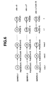
- Fig. 4 illustrates data related to a plurality of imaginary drivers generated by the microcomputer.
- Each imaginary driver retains a series of intentions over, m, in number, points in time ranging from time (t) back to time (t-m+1).
- the microcomputer continuously generates a lane-keeping intention (LK) at every point in time.
- the lane-keeping intentions form a series of intentions for a parent imaginary driver.
- the microcomputer generates data related to at least one additional imaginary driver based on the intention of the parent imaginary driver.
- the microcomputer generates data related to two additional imaginary drivers, each has one of two derivative lane-change intentions (LCR) and (LCL) based on a lane-keeping intention (LK) of the parent imaginary driver at an immediately preceding pint in time.
- LCR derivative lane-change intentions
- LCL lane-keeping intention
- the two additional imaginary drivers generated at a specific point of time assumes at least some of the intentions for all points in time preceding the specific point in time, from the parent imaginary driver.
- the microcomputer applies certain rules in generating series of intentions for existing additional imaginary drivers. For instance, the microcomputer determines whether an imaginary driver retaining one of the derivative lane-change intentions may continue to exist at the next point in time, by applying one or more rules.
- An exemplary rule allows the parent imaginary driver to retain a lane-keeping intention (LK) at every point in time, and generates data related to two additional imaginary drivers having lane-change intentions (LCR) and (LCL), respectively, at the next point in time.
- LCR lane-keeping intention
- LCL lane-change intentions
- an imaginary driver is allowed to retain a lane-change intention to the right (LCR) at the next point in time if it is determined that the real driver continues to retain a lane-changing intention at the present point in time.
- an imaginary driver is not allowed to retain a lane-change intention to the right (LCR) at the next point in time.
- LCR left
- an imaginary driver having a lane-change intention to the left (LCL) at a specific point in time is allowed to retain a lane-change intention to the left (LCL) at the next point in time upon determination that a lane change continues, but the imaginary driver is not allowed to continue to retain a lane-change intention to the left (LCL) at a specific point in time upon failure to determine that the lane change continues. Therefore, an imaginary driver that has one of the derivative lane-change intentions (LCR) and (LCL), is allowed to retain the derivative lane-change intention at the next point in time upon determination that a lane change continues.
- a special memory portion for storing intentions of the parent imaginary driver.
- the intentions include m, in number, lane-keeping intentions (LK), over a period of time ranging from time (t) back to time (t-m+1).
- Each of the remaining memory portions is provided for storing intentions for one of the additional imaginary drivers.
- the inventions include lane-change intention (LCR) or (LCL) over a period of time ranging from time (t) back to time (t-m+1). It is now apparent that, except for the special memory portion provided for the parent imaginary driver, the microcomputer resets any memory portions for the additional imaginary drivers upon determination that the memory portion has contained m, in number, lane-change intentions.
- SEIES L1 corresponds to a series of intentions of an additional imaginary driver that is generated at time t, and includes a lane-change intention to the right (LCR) at time t.
- SERIES L2 includes two lane-change intentions to the right and represents intentions of another additional imaginary driver generated earlier.
- SERIES L3 including (m-3), in number, lane-change intentions to the right (LCR) and represents intentions of still another imaginary driver that is generated earlier than "SERIES L1" and "SERIES L2.".
- the imaginary driver corresponding to "SERIES L1” retains a lane-keeping intention (LK) at every point in time from (t-m+1) to (t-1), and has a lane-change intention to the right (LCR) at the present point in time (t).
- the imaginary driver corresponding to "SERIES L2” retains a lane-keeping intention (LK) from (t-m+1) to (t-2), and has a lane-change intention to the right (LCR) at both (t-1) and (t).
- the imaginary driver corresponding to "SERIES L3" retains a lane-keeping intention (LK) from (t-m+1) to (t-m+2), and a lane-change intention to the right (LCR) at (t-m+3) through (t).
- Figs. 5(a) and 5(b) show rules that the imaginary driver's intention generating section 40 (as shown in Fig. 1) utilizes in determining an intention for each existing driver at each point in time.
- the microcomputer allows a parent imaginary driver having a lane-keeping intention (LK) at every point in time.
- the microcomputer generates data related to two additional imaginary drivers, each has one of two derivative lane-change intentions (LCR) and (LCL) based on a lane-keeping intention (LK) of the parent imaginary driver at an immediately preceding pint in time..
- the microcomputer determines whether or not the vehicle's environment allows a lane-change intention to continue to exist at the next point in time by applying certain rules.
- Fig. 5(b) shows an exemplary rule used by the microcomputer.
- an imaginary driver is allowed to retain a lane-change intention to the right (LCR) at the next point in time, if it is determined that the real driver continues to retain a lane-changing intention at the present point in time.
- an imaginary driver is not allowed to retain a lane-change intention to the right (LCR) at the next point in time .
- an imaginary driver having a lane-change intention to the left (LCL) at a specific point in time is allowed to retain a lane-change intention to the left (LCL) at the next point in time upon determination that a lane change continues, but the imaginary driver is not allowed to continue to retain a lane-change intention to the left (LCL) at a specific point in time upon failure to determine that the lane change continues. Therefore, an imaginary driver that has one of the derivative lane-change intentions (LCR) and (LCL), is allowed to retain the derivative lane-change intention at the next point in time upon determination that a lane change continues.
- the microcomputer determines that the lane-change intention may continue to exist if the vehicle continues to stay in the same lane.
- the microcomputer determines that the lane-change intention has been realized if the vehicle has changed to a different lane.
- the microcomputer fails to determine that the lane-change intention continues.
- lane-change intentions (LCR) and (LCL) at a specific point in time are allowed to continue to exist at the next point in time upon determination that the vehicle continues to stay in the same lane.
- lane-change intentions (LCR) and (LCL) are not allowed to continue to exist at the next point in time upon determination that the vehicle has changed to a different lane.
- all imaginary drivers except for the parent imaginary driver
- LCR derivative lane-change intention
- LCD derivative lane-change intention
- the microcomputer calculates a likelihood value Pid indicating how the calculated operation amount Oid of each imaginary driver approximates the detected operation amount Ord of the real driver.
- the likelihood value Pid is used to represent a likelihood value Pid.lk of an imaginary driver having a lane-keeping intention (LK), a likelihood value Pid.lcr of an imaginary driver having a lane-change to the right (LCR), or a likelihood value Pid.lcl of an imaginary driver having a lane-change intention to the left (LCL).
- the calculated operation amount Oid of each imaginary driver is expressed by any one of the calculated steering angles ⁇ id.lk, id. ⁇ lcr, and ⁇ id.lcl.
- an imaginary driver's steering angle ⁇ id is used to represent any one of these calculated steering angles ⁇ id.lk, ⁇ id.lcr, and ⁇ id.lcl.
- the detected operation amount Ord of the real driver is expressed by the detected steering angle ⁇ rd performed by the real driver.
- the likelihood value Pid of each imaginary driver is a logarithmic probability of a normalized value of the imaginary driver's steering angle ⁇ id relative to a normal distribution, where the mean (e) is the real driver's steering angle ⁇ rd and the variance ( ⁇ ) is a predetermined value prd such as a standard deviation of steering angles.
- the value of prd depends on characteristics of the vehicle, such as the steering gear ratio, and/or the speed of the vehicle. prd may range from -15 degrees to +15 degrees, such as between 3 to 5 degrees. Of course, other values of prd may be used depending on the type and/or characteristics of vehicles.
- Pid log ⁇ Probn [( ⁇ id - ⁇ rd)/ ⁇ rd] ⁇
- Probn is a probability density function that is used to calculate a probability with which a given sample is observed from a population expressed by the normal distribution.
- the microcomputer calculates a likelihood value Pid(t) for each of the imaginary drivers of a dynamic family illustrated in Fig. 4.
- the calculated likelihood values are stored in the memory portions corresponding to each imaginary driver j, and are expressed as Pid(j)(t), where j corresponds to one of the imaginary drivers.
- Pid(j)(t) means a calculated likelihood value for an imaginary driver j having an intention at a point in time (t).
- the microcomputer calculates a collective likelihood value P(j)ids for each imaginary driver j that is designed to behave. as directed by intentions associated with each imaginary driver j.
- the collective likelihood value P(j)ids may be expressed as: Equation 8 states that the collective likelihood value P(j)ids is the product of the respective calculated likelihood values Pid(j)(t) ⁇ Pid(j)(t ⁇ m + 1).
- the microcomputer estimates a real driver's intention ⁇ rd.
- the microcomputer chooses one of the imaginary drivers that has the maximum calculated collective likelihood values P(j)ids among all imaginary drivers.
- the series of intentions corresponding to the chosen imaginary driver is now labeled Lmax.
- the microcomputer chooses the latest intention of the series Lmax to approximate a real driver's intention ⁇ rd.
- the microcomputer determines a state of the estimated real driver's intention ⁇ rd. If, for example, it is determined that the estimated real driver's intention ⁇ rd at the present point in time (t) is a lane-change intention to the right (LCR), a state of the estimated intention ⁇ rd is determined based on data related to the selected imaginary driver that is used to generate the estimated intention . For instance, the state of the estimated intention retained by the real driver may be defined as a period of time that the selected imaginary driver has retained the estimated intention.
- the period of time is the shortest if an imaginary driver corresponding to series "SERIES L1" is selected to approximate the real driver's intention at time t, wherein the imaginary driver has a lane-change intention to the right (LCR) only at time (t).
- the period of time is longer if an imaginary driver associated with series "SERIES L2" is selected to approximate the behaviors of the real driver. This selected imaginary driver retains a lane-change intention to the right (LCR) at both time (t) and (t-1)..
- the period of time is the longest upon selection of an imaginary driver corresponding to series "SERIES L3" to approximate the behaviors of the real driver.
- the imaginary driver corresponding to "SERIES L3" has a lane-change intention to the right (LCR) at time (t-m+3) through (t). This period of time that the selected imaginary driver retains a specific intention is called elapsed time etlc.
- the microcomputer estimates the elapsed time etlc for determining the state of the estimated real driver's intention ⁇ rd.
- step S110 the microcomputer determines whether or not m, in number of, ⁇ did(k) has been retrieved through the memory portion for the series Lmax. If this is not the case, the logic goes to step S111.
- step S111 the microcomputer makes decrement of the variable k by decreasing the variable k by 1 (one). Step S111 allows the variable k to indicate the adjacent next preceding point in time.
- step S109 the microcomputer determines that the estimated real driver's intention ⁇ rd is not equal to ⁇ did(k) of the memory portion for the series Lmax.
- the logic goes to step S112. For example, if ⁇ did(t-m+2) is indicative of an intention (LK) at time (t-m+2) of "SERIES L3", the result of determination at step S109 becomes negative. In this case, the logic goes to step S112. In addition, the logic goes to S112 if the result of determination at step S110 becomes affirmative. The result of determination at step S110 becomes affirmative if all of locations of the memory portion for the series Lmax have been retrieved.
- step S113 After calculating the elapsed time etlc, the logic goes to step S113.
- the microcomputer provides, as an output, the estimated real driver's intention ⁇ rd and elapsed time etlc, which represents the state of the estimated intention.
- steering angles ⁇ rd and ⁇ id are used as operations Ord and Oid of the real driver and the imaginary drivers.
- an accelerator pedal stroke may be used to indicate the operation performed or to be performed by the real driver and imaginary drivers.
- an accelerator pedal stroke Sid of an imaginary driver may be calculated based on a degree. to which the vehicle has approached the preceding vehicle. This degree may be expressed by a distance to the preceding vehicle and time headway THW.
- a likelihood value of the accelerator pedal stroke Sid with respect to an accelerator pedal stroke Srd of a real driver is calculated for estimating a real driver's intention.
- FIG. 7 another exemplary implementation of a driving assistance system 100 accordingto the present disclosure is described. As shown in Fig. 8, a vehicle is installed with the driving assistance system 100.
- the driving assistance system 100 includes a laser radar 110.
- the laser radar 110 is mounted to the vehicle at a front bumper or a front grille thereof.
- Laser radar 110 scans horizontally and laterally about 6 degrees to each side of an axis parallel to the vehicle longitudinal centerline, propagates infrared pulses forwardly and receives reflected radiation by an obstacle, such as a rear bumper of a preceding vehicle.
- the laser radar 110 can provide a distance d to a preceding vehicle and a relative speed Vr to the preceding vehicle.
- the laser radar 110 provides, as outputs, the detected distance d and relative speed Vr to a controller 150.
- the driving assistance system 100 also includes a front camera 120.
- the front camera 120 is of the CCD type or CMOS type and mounted to the vehicle in Fig. 13 in the vicinity of the internal rear view mirror to acquire image data of a region in front of the vehicle.
- the front camera 120 provides, as output signals, the acquired image data to an image processor 130.
- the image processor 130 provides the processed image data to the controller 150.
- the region covered by the front camera 120 extends from the camera axis to each side by 30 degrees.
- the driving assistance system 100 also includes a vehicle speed sensor 140.
- the vehicle speed sensor 140 determines a vehicle speed of the host vehicle by processing outputs from wheel speed sensors.
- the vehicle speed sensor 140 may include an engine controller or a transmission controller, which can provide a signal indicative of the vehicle speed.
- the vehicle speed sensor 140 provides, as an output, the vehicle speed of the host vehicle to the controller 150.
- the driving assistance system 100 also includes system 1 as illustrated in Figs. 1 to 6, to provide an estimated real driver's intention ⁇ rd and a state of the estimated intention, such as the elapsed time etlc, to the controller 150.
- Controller 150 which performs data processing within the driving assistance system 100, may contain a microprocessor including as a central processing unit (CPU), a read only memory (ROM) and a random access memory (RAM).
- the controller 150 includes, for example, software implementation of a risk potential (RP) calculator 151, an accelerator pedal reaction force instruction value FA calculator 152, and an instruction value FA correcting section 153.
- RP risk potential
- the RP calculator 151 calculates a risk potential (RP) associated with the vehicle based on a vehicle speed V1 of the host vehicle, a distance D to the preceding vehicle, and a relative speed Vr to the preceding vehicle, which are provided by the laser radar 110, vehicle speed sensor 140 and image processor 130.
- the RP calculator 151 provides, as an output, the risk potential RP to the accelerator pedal reaction force instruction value FA calculator 152.
- the accelerator pedal reaction force instruction value FA calculator 152 calculates an accelerator pedal reaction force instruction value FA based on the risk potential RP.
- the accelerator pedal reaction force instruction value FA calculator 152 provides, as an output, the accelerator pedal reaction force instruction value FA to the instruction value FA correcting section 153.
- the instruction value FA correcting section 153 corrects the accelerator pedal reaction force instruction value FA based on the estimated driver's intention ⁇ rd and the elapsed time etlc, and generates a corrected accelerator pedal reaction force instruction value FAc.
- the instruction value FA correcting section 153 provides, as an output, the corrected accelerator pedal reaction force instruction value FAc to an accelerator pedal reaction force control unit 170.
- the accelerator pedal reaction force control unit 170 regulates a servo motor 180 of an accelerator pedal 160.
- the accelerator pedal 160 has a link mechanism including a servo motor 180 and an accelerator pedal stroke sensor 181.
- the servo motor 180 may provide any desired torque and any desired angular position in response to an instruction from the accelerator pedal reaction force control unit 170.
- the accelerator pedal stroke sensor 181 detects an accelerator pedal stroke or position S of the accelerator pedal 160 by measuring an angle of the servo motor 180. The angle of the servo motor 180 corresponds to the accelerator pedal stroke S because the servo motor 180 and the accelerator pedal 160 are interconnected by the link mechanism.
- reaction force control unit 170 When the accelerator pedal reaction force control unit 170 is not active, the reaction force increases linearly as the accelerator pedal stroke S increases. This reaction force varying characteristic is accomplished by a spring force provided by a torque spring arranged at the center of rotational movement of the accelerator pedal 160.
- Fig. 10 shows a flow chart illustrating a control routine of a driving assistance control program stored in the controller 150.
- the execution of the control routine is repeated at regular interval of, for example, 50msec.
- the controller 150 recognizes environment in a field around the host vehicle.
- the controller 150 receives, as inputs, signals of the laser radar 110, front camera 120 and vehicle speed sensor 140 by reading operations to acquire data regarding the vehicle's status and the vehicle's environment.
- the acquired data include a vehicle speed V1 of the host vehicle, a vehicle speed V2 of the preceding vehicle, and a relative speed to the preceding vehicle Vr.
- the acquired data may include a coordinate X1 of the host vehicle and a coordinate X2 of the preceding vehicle, and a distance D to the preceding vehicle.
- the controller 150 calculates a risk potential RP associated with the vehicle based on time to collision TTC and time headway THW, which are used as two exemplary notions to calculate the risk potential RP.
- the TTC is an estimated period of time before the distance D becomes zero if the relative speed Vr to the preceding vehicle remains unchanged.
- TTC The smaller the value of TTC, the more imminent a collision is likely to occur.
- the TTC In the traffic scene where the host vehicle is following the preceding vehicle, most vehicle drivers perceive a high degree of risk and initiate deceleration to avoid collision well before the TTC becomes less than 4 seconds. To some extent, the TTC is a good indication for predicting future behaviors that the driver might take. However, when it comes to quantifying the degree of risk, which the vehicle driver actually perceives, the TTC alone is insufficient to quantify the degree of risk.
- the TTC is infinite irrespective of how narrow the distance D is.
- the driver perceives an increase in the degree of risk in response to a reduction in the distance D, accounting for an increase in influence on the TTC by an unpredictable drop in a vehicle speed of the preceding vehicle.
- THW D/V1
- the vehicle speed V2 of the preceding vehicle may be used instead of the vehicle speed V1 in Eq. 13.
- TTC and THW The relationship between the two notions TTC and THW is such that a change in vehicle speed V2, if any, of the preceding vehicle will result in a small change in the TTC when the value of THW is large, but the same change in vehicle speed V2 of the preceding vehicle will result in a large change in the TTC when the value of THW is small.
- the risk potential RP calculated at step S202 is expressed as a sum of a first index and a second index.
- the first index represents a degree that the vehicle has approached the preceding vehicle.
- the second index represents a degree that an unpredictable change in vehicle speed V2 of the preceding vehicle might have influence upon the vehicle.
- the first index may be expressed as a function of the reciprocal of time to collision TTC, and the second index may be expressed as a function of the reciprocal of time headway THW.
- the controller 150 receives, as an input, an accelerator pedal stroke S by reading operation of the output of the accelerator pedal stroke sensor 181.
- the controller 150 calculates an accelerator pedal reaction force instruction value FA.
- the controller 150 calculates a reaction force increment ⁇ F in response to the risk potential RP by, for example, referring to the characteristic curve shown in Fig. 11.
- the curve in Fig. 11 shows reaction force increment ⁇ F relative to different values of risk potential RP.
- the reaction force increment ⁇ F is always zero in order to prevent forwarding unnecessary information to the driver.
- An appropriate value RPmin may be determined empirically.
- reaction force increment ⁇ F increases exponentially as the risk potential RP increases.
- the controller 150 calculates the sum of the reaction force increment ⁇ F and the ordinary reaction force characteristic to provide the accelerator pedal reaction force instruction value FA.
- the controller 150 reads, as an input, the estimated real driver's intention ⁇ rd determined by system 1.
- step S206 the controller 150 determines whether or not the estimated driver's intention ⁇ rd is indicative of a lane-change intention. If this is the case, the logic goes to step S207.
- step S207 the controller 150 reads, as an input, the elapsed time etlc calculated by system 1.
- the controller 150 corrects the accelerator pedal reaction force instruction value FA to provide a corrected accelerator pedal reaction force instruction value FAc.
- the accelerator pedal reaction force instruction value FA is processed by a low-pass filter and decreased.
- Fig. 12 illustrates characteristics of the function f(etlc). As illustrated in Fig. 12, the time constant Tsf etlc decreases as the elapsed time etlc increases, which allows a faster reduction of the accelerator pedal reaction force.
- step S206 the controller 150 determines that the estimated driver's intention ⁇ rd is indicative of a lane-keeping intention (LK), the logic goes to S209.
- the controller 150 sets the accelerator pedal reaction force instruction value FA as the corrected accelerator pedal reaction force instruction value FAc.
- the controller 150 provides, as an output, the corrected accelerator pedal reaction force instruction value FAc that has been determined at step S208 or S209 to the accelerator pedal reaction force control unit 170.
- the accelerator pedal reaction force control unit 170 controls the servo motor 180 in response to the corrected accelerator pedal reaction force instruction value FAc.
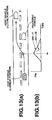
- Fig. 13(a) illustrates a traffic scene in which the host vehicle in changing lanes to pass the preceding vehicle.
- Fig. 13(b) illustrates two curves: L1 (in solid line) and L2 (in dotted line).
- L1 is a curve showing a corrected accelerator pedal reaction force instruction value FAc with elapsed time etlc equal to t1
- L2 is a curve showing a corrected accelerator pedal reaction force instruction value FAc with elapsed time etlc equal to t2, wherein t2 is larger than t1.
- elapsed time etlc is used to indicate a state of an estimated intention of the real driver.
- a driver represented by curve L2 retains a lane-changing intention longer a driver represented by curve L1.
- the corrected accelerator pedal reaction force instruction value FAc controls the reaction force to drop dramatically to allow a smoother manipulation of the accelerator pedal 160 for the lane-change and the subsequent passing of the preceding vehicle.
- the corrected accelerator pedal reaction force instruction value FAc of curve L2 drops faster than that of curve L1 upon determination at time ta that the estimated driver's intention ⁇ rd is indicative of a lane-change intention.
- system 100 modifies the reaction force more dramatically upon determining that the real driver has a stronger intention (reflected by the long etlc t2) to change lanes.
- Fig. 14 shows a flow chart illustrating a control routine of a driving assistance control program stored in the controller 150. The execution of the control routine is repeated at a regular interval of, for example, 50msec.
- the flow chart illustrated in Fig. 14 has steps S301 and 307, which are comparable to steps S201 and S207 of the flow chart illustrated in Fig. 10.
- the controller 150 performs substantially the same tasks down to step S307.
- step S308 the controller 150 determines whether or not the elapsed time etlc is longer than the predetermined value etlc0. If, at step S308, the controller 150 determines that the elapsed time etlc is longer than the predetermined value etlc0, the logic goes to step S309.
- the controller 150 corrects an accelerator pedal reaction force instruction value FA, which has been calculated at step S304, based on the elapsed time etlc. Specifically, the controller 150 corrects the accelerator pedal reaction force FA by calculating the following equation to provide a corrected accelerator pedal reaction force instruction value FAc.
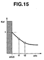
- Fig. 15 illustrates characteristics of function f(etlc).
- the coefficient Ksf falls below 1 as the elapsed time etlc increases above the predetermined value etlc0.
- step S308 If, at step S308, the result of the determination is negative, the logic goes to step S310.
- the controller 150 sets the accelerator pedal reaction force instruction value FA as the corrected accelerator pedal reaction force instruction value FAc.
- the controller 150 provides, as an output, the corrected accelerator pedal reaction force instruction value FAc that has been determined at step S208 or S209 to the accelerator pedal reaction force control unit 170.
- the time constant Tsf etlc is determined based on the elapsed time etlc function shown in Fig. 12, and the coefficient Ksf is multiplied with the time constant Tsf etlc only when the elapsed time etlc is longer the predetermined value etlc0 to provide the corrected accelerator pedal reaction force instruction value Fac.
- the accelerator pedal reaction force instruction value FA remains uncorrected when the elapsed time etlc is equal to or less than the predetermined value etlc0.
- Appropriately setting the predetermined value etlc0 makes it easy to tune the driving assistance system to meet various demands.
- the product of a coefficient Ksf and the time constant Tsf etlc. is provided, and various values of Ksf with different values of the elapsed time etlc are predetermined and retrieved versus the calculated value of the etlc.
- the driving assistance system 200 is substantially the same as the driving assistance system 100 illustrated in Fig. 7. Thus, like reference numerals are used to designate like parts or portions throughout Figs. 7 and 16. However, the driving assistance system 200 is different from the driving assistance system 100 in the following respects:
- the driving assistance system 200 corrects a risk potential RP upon determination that the estimated driver's intention ⁇ rd is indicative of a lane-change intention.
- the driving assistance system 200 includes a controller 150A.
- the controller 150A is provided with a software implementation of a risk potential (RP) calculator 151, a risk potential (RP) correcting section 154, and an accelerator pedal reaction force instruction value FA calculator 155.
- the flow chart in Fig. 17 illustrates a control routine of a driving assistance control program stored in the controller 150A.
- the execution of the control routine is repeated at a constant interval of, for example, 50msec.
- the flow chart illustrated in Fig. 17 has steps S401 and 402, which are comparable to the steps S201 and S202 of the flow chart illustrated in Fig. 10.
- the controller 150A performs substantially the same tasks down to step S402.
- the controller 150A reads, as an input, an estimated real driver's intention ⁇ rd determined at a real driver's intention estimating system 1 (see Fig. 16).
- step S404 the controller 150A determines whether or not the estimated driver's intention ⁇ rd is indicative of a lane-change intention. If this is the case, the logic goes to step S405.
- the controller 150A reads, as an input, the elapsed time etlc calculated at the real driver's intention estimating system 1.
- the controller 150A corrects the risk potential RP to provide a corrected risk potential RPc.
- the risk potential RP is processed by a low-pass filter and decreased.
- Fig. 18 illustrates characteristics of the function f(etlc). As illustrated in Fig. 18, the time constant Tsp etlc decreases as the elapsed time etlc increases. Setting the time constant Tsp etlc in this way allows a faster reduction of the accelerator pedal reaction force by lowering the risk potential RP.
- step S404 the controller 150A determines that the estimated driver's intention ⁇ rd is indicative of a lane-keeping intention, the logic goes to S407.
- the controller 150A sets the risk potential RP as the corrected risk potential RPc.
- the controller 150A receives, as an input, an accelerator pedal stroke S by reading operation of the output of an accelerator pedal stroke sensor 181.
- the controller 150A calculates an accelerator pedal reaction force instruction value FA.
- the controller 150A calculates a reaction force increment ⁇ F in response to the corrected risk potential RPc by, for example, referring to the characteristic curve shown in Fig. 11. Then, the controller 150A calculates the sum of the reaction force increment ⁇ F and the ordinary reaction force characteristic to provide an accelerator pedal reaction force instruction value FA.
- the controller 150A provides, as an output, the accelerator pedal reaction force instruction value FA to an accelerator pedal reaction force control unit 170.
- the accelerator pedal reaction force control unit 170 controls a servo motor 180 in response to the accelerator pedal reaction force instruction value FA.
- Fig. 19(a) illustrates a traffic scene in which the host vehicle is changing lanes to pass the preceding vehicle.
- Fig. 19(b) illustrates two curves, L1 (in solid line) and L2 (in dotted line), of the corrected accelerator pedal reaction force instruction value FA in response to the estimated driver's lane-change intention. As illustrated by L1 and L2, at time ta, it is determined that the estimated driver's intention ⁇ rd is indicative of a lane-change intention.
- the accelerator pedal reaction force instruction value FA drops to allow a smooth driver's manipulation of the accelerator pedal 160 for the lane-change and the subsequent passing the preceding vehicle.
- curve L1 illustrates that the accelerator pedal reaction force instruction value FA drops gradually when the elapsed time etlc is equal to t1.
- curve L2 illustrates that the accelerator pedal reaction force instruction value FA drops quickly when the elapsed time etlc is equal to t2, wherein t2 is larger than t1.
- the controller 150A is provided with the risk potential RP correcting section 154, which corrects the relationship between the obstacle state, including the preceding vehicle, around the host vehicle and the risk potential RP.
- the risk potential RP correcting section 154 further decreases the risk potential RP as the elapsed time etlc increases upon determination of the estimated driver's intention ⁇ rd. This make it possible to a faster drop of the accelerator pedal reaction force to meet the driver's expectation that the accelerator pedal reaction force be quickly reduced after the driver has retained the lane-change intention for a long period of time.
- Fig. 20 shows a flow chart illustrating a control routine of a driving assistance control program stored in the controller 150A. The execution of the control routine is repeated at a regular interval of, for example, 50msec.
- the flow chart illustrated in Fig. 20 has steps S501 and S505, which are comparable to the steps S401 and S405 of the flow chart illustrated in Fig. 17.
- the controller 150A performs substantially the same jobs down to step S505.
- step S506 the controller 150A determines whether or not elapsed time etlc is longer than a predetermined value etlc0. If, at step S506, the controller 150A determines that the elapsed time etlc is longer than the predetermined value etlc0, the logic goes to step S507.
- the controller 150A corrects a risk potential RP, which has been calculated at step S502, based on the elapsed time etlc. Specifically, the controller 150A corrects the risk potential RP by calculating the following equation to provide a corrected risk potential RPc.
- kp is an appropriately determined constant
- Tsp etlc is a time constant of the low-pass filter
- Ksp is a coefficient, which is a function of the elapsed time etlc and may be expressed as:
- Ksp f(etlc)
- Fig. 21 illustrates characteristics of function f(etlc).
- the coefficient Ksp decreases below 1 as the elapsed time etlc increases above the predetermined value etlc0.
- step S506 If, at step S506, the result of the determination is negative, the logic goes to step S508.
- the controller 150A sets the risk potential RP as the corrected risk potential RPc.
- the controller 150A receives, as an input, an accelerator pedal stroke S by reading operation of the output of an accelerator pedal stroke sensor 181.
- the controller 150A calculates an accelerator pedal reaction force instruction value FA.
- the controller 150A calculates a reaction force increment ⁇ F in response to the corrected risk potential RPc by, for example, referring to the characteristic curve shown in Fig. 11. Then, the controller 150A calculates the sum of the reaction force increment ⁇ F and the ordinary reaction force characteristic to provide an accelerator pedal reaction force instruction value FA.
- the controller 150A provides, as an output, the accelerator pedal reaction force instruction value FA to an accelerator pedal reaction force control unit 170.
- the accelerator pedal reaction force control unit 170 controls a servo motor 180 in response to the accelerator pedal reaction force instruction value FA.
- the time constant Tsp etlc is determined based on the elapsed time etlc function illustrated in Fig. 18 of the, and the coefficient Ksp is multiplied by the time constant Tsp etlc only when the elapsed time etlc is longer the predetermined value etlc0, to provide the corrected risk potential RPc.
- the accelerator pedal reaction force instruction value FA remains uncorrected when the elapsed time etlc is equal to or shorter than the predetermined value etlc0.
- Appropriately setting the predetermined value etlc0 makes it easy to tune the driving assistance system to meet various demands.
- the time constant Tsp etlc may be set as a constant value.
- the product of a coefficient Ksp and the time constant Tsp etlc is provided, and various values of Ksp with different values of the elapsed time etlc are predetermined and retrieved depending on the calculated value of the etlc.
- the risk potential RP is determined by the reciprocal of TTC and the reciprocal of THW. If desired, a risk potential RP might be a function of the reciprocal of TTC only.
Landscapes
- Engineering & Computer Science (AREA)
- Automation & Control Theory (AREA)
- Transportation (AREA)
- Mechanical Engineering (AREA)
- Human Computer Interaction (AREA)
- Physics & Mathematics (AREA)
- Mathematical Physics (AREA)
- Control Of Driving Devices And Active Controlling Of Vehicle (AREA)
- Traffic Control Systems (AREA)
- Auxiliary Drives, Propulsion Controls, And Safety Devices (AREA)
- Controls For Constant Speed Travelling (AREA)
- Operation Control Of Excavators (AREA)
Abstract
Description

The corrected accelerator pedal reaction force instruction value FAc of curve L2 drops faster than that of curve L1 upon determination at time ta that the estimated driver's intention λrd is indicative of a lane-change intention. In other words,
Claims (23)
- An operation assistance method comprising the steps of:detecting an operation performed by an operator of a machine;generating data related to an estimated intention of the operator based on the detected operation; andidentifying a state of the estimated intention of the operator.
- The method of claim 1, wherein the step of identifying the state of the estimated intention of the operator includes the steps of:generating data related to an estimated period of time that the operator retains the estimated intention; andgenerating the state of the estimated intention based on the estimated period of time.
- The method of claim 2, wherein the step of generating data related to an estimated period of time comprises the steps of:generating data related to an estimated intention of the operator at a specific point in time and at least one past estimated intention of the operator before the specific point in time; andgenerating data related to the estimated period of time based on the data related to the estimated intention of the operator at the specific point in time and the at least one past estimated intention of the operator before the specific point in time.
- The method of claim 1, wherein:the machine is a vehicle; andthe operator is a driver of the vehicle.
- The method of claim 1, wherein:the detecting step detects an operation of the operator at each one of different points in time; andthe step of generating data related to an estimated intention of the operator comprises the steps of:providing data related to a plurality of imaginary operators, each of the plurality of imaginary operators associated with a sequence of intentions corresponding to the different points in time, wherein each of the sequence of intentions is associated with an operation;for each imaginary operator, calculating a likelihood value based on partial likelihood values of each imaginary operator corresponding to the different points in time, wherein each of the partial likelihood values is respectively associated with each of the sequence of intentions and the respective operation at each one of the different points in time, and is generated based on the respective detected operation of the real operator at each one of the different points in time and the respective operation of the respective one of the plurality of imaginary operators at each one of the different points in time;selecting one of the plurality of imaginary operators based on the likelihood value of each one of the imaginary operators; andgenerating the estimated intention of the real operator based on a chosen intention of the selected one of the imaginary operators.
- The method of claim 5, wherein the step of generating data related to an estimated intention of the operator comprises the steps of:determining the point in time corresponding to the chosen intention;for the selected one of the plurality of imaginary operators, determining the point in time corresponding to the last intention in the sequence of intentions that is different from the chosen intention; anddetermining a period of time that the chosen intention is retained by the selected one of the plurality of imaginary operators, based on the point in time corresponding to the chosen intention and the point in time corresponding to the last intention in the sequence of intentions that is different from the chosen intention;
andgenerating the state of the estimated intention based on the determined period of time. - The method of claim 4 further comprising the steps of:calculating a risk potential associated with the vehicle;calculating a reaction force based on the calculated risk potential, the estimated intention and the state of the estimated intention; andapplying the reaction force to a vehicle control device of the vehicle.
- The method of claim 7, wherein the vehicle control device is an acceleration pedal or a steering wheel.
- The method of claim 7, wherein the step of calculating a reaction force comprises the steps of:modifying the risk potential based on the state of the estimated intention; andcalculating the reaction force based on the modified risk potential and the estimated intention.
- The method of claim 7, wherein the step of calculating a reaction force comprises the steps of:calculating the reaction force based on the calculated risk potential and the estimated intention; andmodifying the calculated reaction force based on the state of the estimated intention.
- The method of claim 1 further comprising the step of modifying the operation of the machine based on the state of the estimated intention of the operator.
- An operation assistance system comprising:a first device configured to detect an operation performed by an operator of a machine;a second device configured to generate data related to an estimated intention of the operator based on the detected operation; anda third device configured to identify a state of the estimated intention of the operator.
- The method of claim 12, wherein the third device is configured to generate data related to an estimated period of time that the operator retains the estimated intention, and to generate the state of the estimated intention based on the estimated period of time.
- The method of claim 13, wherein the third device is configured to generate data related to an estimated intention of the operator at a specific point in time and at least one past estimated intention of the operator before the specific point in time, and to generate data related to the estimated period of time based on the data related to the estimated intention of the operator at the specific point in time and the at least one past estimated intention of the operator before the specific point in time.
- The system of claim 12, wherein:the machine is a vehicle; andthe operator is a driver of the vehicle.
- The system of claim 12, wherein:the first device is configured to detect an operation of the operator at each one of different points in time; andthe second device is configured to perform the steps of:providing data related to a plurality of imaginary operators, each of the plurality of imaginary operators associated with a sequence of intentions corresponding to the different points in time, wherein each of the sequence of intentions is associated with an operation;for each imaginary operator, calculating a likelihood value based on partial likelihood values of each imaginary operator corresponding to the different points in time, wherein each of the partial likelihood values is respectively associated with each of the sequence of intentions and the respective operation at each one of the different points in time, and is generated based on the respective detected operation of the real operator at each one of the different points in time and the respective operation of the respective one of the plurality of imaginary operators at each one of the different points in time;selecting one of the plurality of imaginary operators based on the likelihood value of each one of the imaginary operators;. andgenerating the estimated intention of the real operator based on a chosen intention of the selected one of the imaginary operators.
- The system of claim 16, wherein second device is configured to perform the steps of:determining the point in time corresponding to the chosen intention;for the selected one of the plurality of imaginary operators, determining the point in time corresponding to the last intention in the sequence of intentions that is different from the chosen intention; anddetermining a period of time that the chosen intention is retained by the selected one of the plurality of imaginary operators, based on the point in time corresponding to the chosen intention and the point in time corresponding to the last intention in the sequence of intentions that is different from the chosen intention; generating the state of the estimated intention based on the determined period of time.
- The system of claim 15 further comprising:a risk calculation device configured to calculate a risk potential associated with the vehicle;a reaction force calculation device configured to calculate a reaction force based on the calculated risk potential, the estimated intention and the state of the estimated intention; andapplying the reaction force to a vehicle control device of the vehicle.
- The system of claim 18, wherein the vehicle control device is an acceleration pedal or a steering wheel.
- An operation assistance system comprising:means for detecting an operation performed by an operator of a machine;means for generating data related to an estimated intention of the operator based on the detected operation; andmeans for identifying a state of the estimated intention of the operator.
- A machine-readable medium bearing instructions for assisting operation of a machine, the instructions, upon execution by a data processing system, causing the data processing system to perform the steps of:receiving data related to an operation performed by an operator of the machine;generating data related to an estimated intention of the operator based on the detected operation; andidentifying a state of the estimated intention of the operator.
- A vehicle comprising:a first device configured to detect an operation performed by a driver of the vehicle;a second device configured to generate data related to an estimated intention of the driver based on the detected operation; anda third device configured to identify a state of the estimated intention of the driver.
- The vehicle of claim 22 further comprising a control device to control the operation of the vehicle based on the identified state of the estimated intention of the driver.
Applications Claiming Priority (2)
| Application Number | Priority Date | Filing Date | Title |
|---|---|---|---|
| JP2003417745 | 2003-12-16 | ||
| JP2003417745A JP4561092B2 (en) | 2003-12-16 | 2003-12-16 | VEHICLE DRIVE OPERATION ASSISTANCE DEVICE AND VEHICLE HAVING VEHICLE DRIVE OPERATION ASSISTANCE DEVICE |
Publications (3)
| Publication Number | Publication Date |
|---|---|
| EP1544022A2 true EP1544022A2 (en) | 2005-06-22 |
| EP1544022A3 EP1544022A3 (en) | 2006-11-22 |
| EP1544022B1 EP1544022B1 (en) | 2009-02-25 |
Family
ID=34510611
Family Applications (1)
| Application Number | Title | Priority Date | Filing Date |
|---|---|---|---|
| EP04029611A Expired - Lifetime EP1544022B1 (en) | 2003-12-16 | 2004-12-14 | Operation assistance system and method |
Country Status (4)
| Country | Link |
|---|---|
| US (1) | US7386371B2 (en) |
| EP (1) | EP1544022B1 (en) |
| JP (1) | JP4561092B2 (en) |
| DE (1) | DE602004019622D1 (en) |
Cited By (4)
| Publication number | Priority date | Publication date | Assignee | Title |
|---|---|---|---|---|
| EP2088048A1 (en) * | 2008-02-08 | 2009-08-12 | Airmax Group Plc. | Method of and system for configuring of an electronic control system for controlling the operation of at least one component of a vehicle |
| WO2010052236A1 (en) * | 2008-11-07 | 2010-05-14 | Verhey Van Wijk Beheer B.V. | Tactile speed control assist for car drivers |
| FR2954744A1 (en) * | 2009-12-28 | 2011-07-01 | Continental Automotive France | METHOD FOR DETERMINING A PARAMETER REPRESENTATIVE OF THE VIGILANCE STATUS OF A VEHICLE DRIVER |
| CN109476311A (en) * | 2016-05-27 | 2019-03-15 | 日产自动车株式会社 | Driving control method and driving control device |
Families Citing this family (20)
| Publication number | Priority date | Publication date | Assignee | Title |
|---|---|---|---|---|
| JP4226455B2 (en) * | 2003-12-16 | 2009-02-18 | 日産自動車株式会社 | Driving intention estimation device, vehicle driving assistance device, and vehicle equipped with vehicle driving assistance device |
| DE102004033487B4 (en) * | 2004-07-10 | 2006-03-16 | Bayerische Motoren Werke Ag | Device for generating a haptic signal in a vehicle |
| US20060062764A1 (en) * | 2004-08-25 | 2006-03-23 | Seshidar-Reddy Police | Fiber-modified adenoviral vectors for enhanced transduction of tumor cells |
| JP4367319B2 (en) * | 2004-11-12 | 2009-11-18 | 日産自動車株式会社 | VEHICLE DRIVE OPERATION ASSISTANCE DEVICE AND VEHICLE HAVING VEHICLE DRIVE OPERATION ASSISTANCE DEVICE |
| JP4229051B2 (en) * | 2004-11-26 | 2009-02-25 | 日産自動車株式会社 | Driving intention estimation device, vehicle driving assistance device, and vehicle equipped with vehicle driving assistance device |
| JP4062310B2 (en) * | 2005-02-07 | 2008-03-19 | 日産自動車株式会社 | Driving intention estimation device, vehicle driving assistance device, and vehicle equipped with vehicle driving assistance device |
| DE102005039103A1 (en) * | 2005-08-18 | 2007-03-01 | Robert Bosch Gmbh | Procedure for recording a traffic area |
| CN1996194A (en) * | 2005-12-31 | 2007-07-11 | 清华大学 | A moving object positioning and correction system and its motion tracking method |
| CN101506765B (en) * | 2006-11-10 | 2011-05-25 | 松下电器产业株式会社 | Purpose estimation device and purpose estimation method |
| US8063754B2 (en) * | 2006-12-15 | 2011-11-22 | Honda Motor Co., Ltd. | Vehicle state information transmission apparatus using tactile device |
| US8527187B2 (en) * | 2007-03-13 | 2013-09-03 | GM Global Technology Operations LLC | Systems and methods for digital signal processing |
| JP5142736B2 (en) * | 2008-01-25 | 2013-02-13 | 株式会社デンソーアイティーラボラトリ | Control device and control method for on-vehicle equipment |
| JP5531896B2 (en) | 2010-02-04 | 2014-06-25 | 日産自動車株式会社 | Electric hydraulic device and hydraulic oil temperature control method for electric hydraulic device |
| JP5597708B2 (en) | 2010-06-18 | 2014-10-01 | 本田技研工業株式会社 | A system that predicts the driver's intention to change lanes |
| KR101461878B1 (en) * | 2013-03-18 | 2014-11-14 | 현대자동차 주식회사 | System and method of determining long term driving tendency of driver |
| DE102015212250A1 (en) * | 2015-06-30 | 2017-01-05 | Conti Temic Microelectronic Gmbh | Improved calculation of time to collision for a vehicle |
| JP6624158B2 (en) * | 2017-05-22 | 2019-12-25 | 株式会社デンソー | Electronic control unit |
| US11142196B2 (en) * | 2019-02-03 | 2021-10-12 | Denso International America, Inc. | Lane detection method and system for a vehicle |
| CN109808493B (en) * | 2019-02-19 | 2021-05-28 | 百度在线网络技术(北京)有限公司 | Method and device for displaying driving behavior of automatic driving vehicle |
| JP2023174313A (en) * | 2022-05-27 | 2023-12-07 | トヨタ自動車株式会社 | Vehicle control device, vehicle, vehicle control method and program |
Family Cites Families (26)
| Publication number | Priority date | Publication date | Assignee | Title |
|---|---|---|---|---|
| US5189621A (en) * | 1987-05-06 | 1993-02-23 | Hitachi, Ltd. | Electronic engine control apparatus |
| JP3273800B2 (en) * | 1991-11-11 | 2002-04-15 | 茂 近藤 | Car driving analysis diagnosis method and device |
| JP3214122B2 (en) * | 1993-01-19 | 2001-10-02 | 三菱電機株式会社 | Danger situation alarm device |
| JP3039325B2 (en) * | 1995-06-22 | 2000-05-08 | 三菱自動車工業株式会社 | Clutch control device for accumulator type hybrid vehicle |
| DE19536512A1 (en) * | 1995-09-29 | 1997-04-03 | Bayerische Motoren Werke Ag | Gear change control for automatic transmissions in motor vehicles with an electronic control unit |
| DE19620929A1 (en) * | 1996-05-24 | 1997-11-27 | Porsche Ag | Longitudinal control system for motor vehicles with accelerator pedal with feel characteristic |
| JPH10103098A (en) * | 1996-10-01 | 1998-04-21 | Unisia Jecs Corp | Vehicle control device |
| JPH10166934A (en) * | 1996-12-13 | 1998-06-23 | Koito Mfg Co Ltd | Lamp device for vehicle |
| US6185492B1 (en) * | 1997-07-09 | 2001-02-06 | Toyota Jidosha Kabushiki Kaisha | Vehicle steering control apparatus for assisting a steering effort to move a vehicle along a line desired by a driver |
| DE19736756A1 (en) * | 1997-08-23 | 1999-02-25 | Volkswagen Ag | Distance control method and device for a vehicle |
| JP4069481B2 (en) * | 1997-09-30 | 2008-04-02 | 日産自動車株式会社 | Vehicle behavior estimation device |
| JP3627499B2 (en) * | 1998-02-10 | 2005-03-09 | 日産自動車株式会社 | Vehicle control device |
| JP3769938B2 (en) * | 1998-03-10 | 2006-04-26 | 日産自動車株式会社 | Lane keeping system |
| JP4120127B2 (en) * | 2000-02-23 | 2008-07-16 | アイシン・エィ・ダブリュ株式会社 | Control device for automatic transmission |
| JP3600518B2 (en) * | 2000-10-11 | 2004-12-15 | トヨタ自動車株式会社 | Vehicle speed change control device |
| JP2002331850A (en) * | 2001-05-07 | 2002-11-19 | Nissan Motor Co Ltd | Driving behavior intention detection device |
| JP4042477B2 (en) * | 2001-12-21 | 2008-02-06 | 日産自動車株式会社 | Driving assistance device for vehicle |
| DE60226817D1 (en) | 2001-08-23 | 2008-07-10 | Nissan Motor | Driving Assistance System |
| JP2003154960A (en) * | 2001-09-04 | 2003-05-27 | Honda Motor Co Ltd | Vehicle steering control device |
| EP1347214B1 (en) * | 2002-03-21 | 2010-05-05 | Continental Automotive GmbH | Control method for an automatic transmission |
| JP2003276543A (en) * | 2002-03-22 | 2003-10-02 | Mitsubishi Electric Corp | Rear side monitoring device for vehicles |
| US6879896B2 (en) * | 2002-04-11 | 2005-04-12 | Delphi Technologies, Inc. | System and method for using vehicle operator intent to adjust vehicle control system response |
| JP4173324B2 (en) | 2002-06-20 | 2008-10-29 | 日産自動車株式会社 | Accelerator pedal device |
| JP3700682B2 (en) | 2002-06-20 | 2005-09-28 | 日産自動車株式会社 | Accelerator pedal device |
| JP3838166B2 (en) * | 2002-06-20 | 2006-10-25 | 日産自動車株式会社 | Driving assistance device for vehicle |
| JP3938023B2 (en) * | 2002-11-27 | 2007-06-27 | 日産自動車株式会社 | Risk potential calculation device, vehicle driving assistance device, vehicle equipped with the device, and risk potential calculation method |
-
2003
- 2003-12-16 JP JP2003417745A patent/JP4561092B2/en not_active Expired - Fee Related
-
2004
- 2004-12-14 DE DE602004019622T patent/DE602004019622D1/en not_active Expired - Lifetime
- 2004-12-14 EP EP04029611A patent/EP1544022B1/en not_active Expired - Lifetime
- 2004-12-16 US US11/012,208 patent/US7386371B2/en not_active Expired - Fee Related
Cited By (6)
| Publication number | Priority date | Publication date | Assignee | Title |
|---|---|---|---|---|
| EP2088048A1 (en) * | 2008-02-08 | 2009-08-12 | Airmax Group Plc. | Method of and system for configuring of an electronic control system for controlling the operation of at least one component of a vehicle |
| WO2010052236A1 (en) * | 2008-11-07 | 2010-05-14 | Verhey Van Wijk Beheer B.V. | Tactile speed control assist for car drivers |
| FR2954744A1 (en) * | 2009-12-28 | 2011-07-01 | Continental Automotive France | METHOD FOR DETERMINING A PARAMETER REPRESENTATIVE OF THE VIGILANCE STATUS OF A VEHICLE DRIVER |
| WO2011079886A1 (en) * | 2009-12-28 | 2011-07-07 | Continental Automotive France | Method for determining a parameter representative of the state of vigilance of a vehicle driver |
| CN109476311A (en) * | 2016-05-27 | 2019-03-15 | 日产自动车株式会社 | Driving control method and driving control device |
| CN109476311B (en) * | 2016-05-27 | 2022-03-01 | 日产自动车株式会社 | Driving control method and driving control device |
Also Published As
| Publication number | Publication date |
|---|---|
| EP1544022A3 (en) | 2006-11-22 |
| JP4561092B2 (en) | 2010-10-13 |
| JP2005182124A (en) | 2005-07-07 |
| US20050131590A1 (en) | 2005-06-16 |
| US7386371B2 (en) | 2008-06-10 |
| EP1544022B1 (en) | 2009-02-25 |
| DE602004019622D1 (en) | 2009-04-09 |
Similar Documents
| Publication | Publication Date | Title |
|---|---|---|
| EP1544022B1 (en) | Operation assistance system and method | |
| EP1544070B1 (en) | Method and system for estimating the intention of a driver of a vehicle with confidence indication | |
| US7778742B2 (en) | Method and system for intention estimation and operation assistance | |
| US7349767B2 (en) | Method and system for intention estimation and operation assistance | |
| US7634331B2 (en) | Driving intention estimation system, vehicle operation assistance system, and vehicle equipped therewith | |
| CN110733501B (en) | Methods for automatic collision avoidance | |
| EP1533170B1 (en) | Assisting system for an accelerator pedal | |
| US12202515B2 (en) | Vehicle control system | |
| EP3855205A1 (en) | Perception performance evaluation of a vehicle adas or ads | |
| US7715972B2 (en) | Driving assisting system for a vehicle and a vehicle installed with the system | |
| EP1484212A1 (en) | Risk potential calculation device and driving assist system | |
| US20210323545A1 (en) | Driver assistance apparatus | |
| KR20230073985A (en) | Vehicle information processing device, vehicle information processing method, and non-transitory storage medium | |
| US11072325B2 (en) | Drive assist device, drive assist method and non-transitory computer readable storage medium for storing programs thereof | |
| CN108944949A (en) | The method for operating the congestion auxiliary system of vehicle | |
| JP2012014713A (en) | Operation aiding method, operation aiding device, control program, and vehicle | |
| US12462616B2 (en) | Information processing device, vehicle, information processing method, and non-transitory storage medium | |
| JP2010049719A (en) | Device for estimating driving intention, driving operation assist device for vehicle, and vehicle equipped with driving operation assist device for vehicle | |
| JP4924524B2 (en) | Driver state estimation device | |
| CN121375768A (en) | Car following control method, computer program product and electronic equipment |
Legal Events
| Date | Code | Title | Description |
|---|---|---|---|
| PUAI | Public reference made under article 153(3) epc to a published international application that has entered the european phase |
Free format text: ORIGINAL CODE: 0009012 |
|
| 17P | Request for examination filed |
Effective date: 20041214 |
|
| AK | Designated contracting states |
Kind code of ref document: A2 Designated state(s): AT BE BG CH CY CZ DE DK EE ES FI FR GB GR HU IE IS IT LI LT LU MC NL PL PT RO SE SI SK TR |
|
| AX | Request for extension of the european patent |
Extension state: AL BA HR LV MK YU |
|
| PUAL | Search report despatched |
Free format text: ORIGINAL CODE: 0009013 |
|
| AK | Designated contracting states |
Kind code of ref document: A3 Designated state(s): AT BE BG CH CY CZ DE DK EE ES FI FR GB GR HU IE IS IT LI LT LU MC NL PL PT RO SE SI SK TR |
|
| AX | Request for extension of the european patent |
Extension state: AL BA HR LV MK YU |
|
| 17Q | First examination report despatched |
Effective date: 20070416 |
|
| AKX | Designation fees paid |
Designated state(s): DE FR GB |
|
| GRAP | Despatch of communication of intention to grant a patent |
Free format text: ORIGINAL CODE: EPIDOSNIGR1 |
|
| GRAS | Grant fee paid |
Free format text: ORIGINAL CODE: EPIDOSNIGR3 |
|
| GRAA | (expected) grant |
Free format text: ORIGINAL CODE: 0009210 |
|
| AK | Designated contracting states |
Kind code of ref document: B1 Designated state(s): DE FR GB |
|
| REG | Reference to a national code |
Ref country code: GB Ref legal event code: FG4D |
|
| REF | Corresponds to: |
Ref document number: 602004019622 Country of ref document: DE Date of ref document: 20090409 Kind code of ref document: P |
|
| PLBE | No opposition filed within time limit |
Free format text: ORIGINAL CODE: 0009261 |
|
| STAA | Information on the status of an ep patent application or granted ep patent |
Free format text: STATUS: NO OPPOSITION FILED WITHIN TIME LIMIT |
|
| 26N | No opposition filed |
Effective date: 20091126 |
|
| REG | Reference to a national code |
Ref country code: FR Ref legal event code: PLFP Year of fee payment: 12 |
|
| PGFP | Annual fee paid to national office [announced via postgrant information from national office to epo] |
Ref country code: GB Payment date: 20151209 Year of fee payment: 12 Ref country code: DE Payment date: 20151208 Year of fee payment: 12 |
|
| PGFP | Annual fee paid to national office [announced via postgrant information from national office to epo] |
Ref country code: FR Payment date: 20151110 Year of fee payment: 12 |
|
| REG | Reference to a national code |
Ref country code: DE Ref legal event code: R119 Ref document number: 602004019622 Country of ref document: DE |
|
| GBPC | Gb: european patent ceased through non-payment of renewal fee |
Effective date: 20161214 |
|
| REG | Reference to a national code |
Ref country code: FR Ref legal event code: ST Effective date: 20170831 |
|
| PG25 | Lapsed in a contracting state [announced via postgrant information from national office to epo] |
Ref country code: FR Free format text: LAPSE BECAUSE OF NON-PAYMENT OF DUE FEES Effective date: 20170102 |
|
| PG25 | Lapsed in a contracting state [announced via postgrant information from national office to epo] |
Ref country code: GB Free format text: LAPSE BECAUSE OF NON-PAYMENT OF DUE FEES Effective date: 20161214 Ref country code: DE Free format text: LAPSE BECAUSE OF NON-PAYMENT OF DUE FEES Effective date: 20170701 |